EP2243946A2 - Actuators system - Google Patents
Actuators system Download PDFInfo
- Publication number
- EP2243946A2 EP2243946A2 EP10250765A EP10250765A EP2243946A2 EP 2243946 A2 EP2243946 A2 EP 2243946A2 EP 10250765 A EP10250765 A EP 10250765A EP 10250765 A EP10250765 A EP 10250765A EP 2243946 A2 EP2243946 A2 EP 2243946A2
- Authority
- EP
- European Patent Office
- Prior art keywords
- drive
- arrangement
- gear
- actuators
- dry
- Prior art date
- Legal status (The legal status is an assumption and is not a legal conclusion. Google has not performed a legal analysis and makes no representation as to the accuracy of the status listed.)
- Withdrawn
Links
Images

Classifications
-
- F—MECHANICAL ENGINEERING; LIGHTING; HEATING; WEAPONS; BLASTING
- F02—COMBUSTION ENGINES; HOT-GAS OR COMBUSTION-PRODUCT ENGINE PLANTS
- F02K—JET-PROPULSION PLANTS
- F02K1/00—Plants characterised by the form or arrangement of the jet pipe or nozzle; Jet pipes or nozzles peculiar thereto
- F02K1/54—Nozzles having means for reversing jet thrust
- F02K1/76—Control or regulation of thrust reversers
- F02K1/763—Control or regulation of thrust reversers with actuating systems or actuating devices; Arrangement of actuators for thrust reversers
-
- F—MECHANICAL ENGINEERING; LIGHTING; HEATING; WEAPONS; BLASTING
- F05—INDEXING SCHEMES RELATING TO ENGINES OR PUMPS IN VARIOUS SUBCLASSES OF CLASSES F01-F04
- F05D—INDEXING SCHEME FOR ASPECTS RELATING TO NON-POSITIVE-DISPLACEMENT MACHINES OR ENGINES, GAS-TURBINES OR JET-PROPULSION PLANTS
- F05D2270/00—Control
- F05D2270/60—Control system actuates means
- F05D2270/62—Electrical actuators
-
- F—MECHANICAL ENGINEERING; LIGHTING; HEATING; WEAPONS; BLASTING
- F16—ENGINEERING ELEMENTS AND UNITS; GENERAL MEASURES FOR PRODUCING AND MAINTAINING EFFECTIVE FUNCTIONING OF MACHINES OR INSTALLATIONS; THERMAL INSULATION IN GENERAL
- F16H—GEARING
- F16H25/00—Gearings comprising primarily only cams, cam-followers and screw-and-nut mechanisms
- F16H25/18—Gearings comprising primarily only cams, cam-followers and screw-and-nut mechanisms for conveying or interconverting oscillating or reciprocating motions
- F16H25/20—Screw mechanisms
- F16H2025/2062—Arrangements for driving the actuator
- F16H2025/2084—Perpendicular arrangement of drive motor to screw axis
-
- F—MECHANICAL ENGINEERING; LIGHTING; HEATING; WEAPONS; BLASTING
- F16—ENGINEERING ELEMENTS AND UNITS; GENERAL MEASURES FOR PRODUCING AND MAINTAINING EFFECTIVE FUNCTIONING OF MACHINES OR INSTALLATIONS; THERMAL INSULATION IN GENERAL
- F16H—GEARING
- F16H57/00—General details of gearing
- F16H57/04—Features relating to lubrication or cooling or heating
- F16H57/041—Coatings or solid lubricants, e.g. anti-seize layers or pastes
-
- Y—GENERAL TAGGING OF NEW TECHNOLOGICAL DEVELOPMENTS; GENERAL TAGGING OF CROSS-SECTIONAL TECHNOLOGIES SPANNING OVER SEVERAL SECTIONS OF THE IPC; TECHNICAL SUBJECTS COVERED BY FORMER USPC CROSS-REFERENCE ART COLLECTIONS [XRACs] AND DIGESTS
- Y02—TECHNOLOGIES OR APPLICATIONS FOR MITIGATION OR ADAPTATION AGAINST CLIMATE CHANGE
- Y02T—CLIMATE CHANGE MITIGATION TECHNOLOGIES RELATED TO TRANSPORTATION
- Y02T50/00—Aeronautics or air transport
- Y02T50/60—Efficient propulsion technologies, e.g. for aircraft
-
- Y—GENERAL TAGGING OF NEW TECHNOLOGICAL DEVELOPMENTS; GENERAL TAGGING OF CROSS-SECTIONAL TECHNOLOGIES SPANNING OVER SEVERAL SECTIONS OF THE IPC; TECHNICAL SUBJECTS COVERED BY FORMER USPC CROSS-REFERENCE ART COLLECTIONS [XRACs] AND DIGESTS
- Y10—TECHNICAL SUBJECTS COVERED BY FORMER USPC
- Y10T—TECHNICAL SUBJECTS COVERED BY FORMER US CLASSIFICATION
- Y10T74/00—Machine element or mechanism
- Y10T74/18—Mechanical movements
- Y10T74/18056—Rotary to or from reciprocating or oscillating
Definitions
- This invention relates to an actuator system for use in aerospace applications, and in particular to an electrically powered thrust reverser actuator system.
- a typical thrust reverser system includes a number of movable components which are each arranged to be driven, in use, between a stowed position and a deployed position.
- Many systems are known in which hydraulic actuators are used to drive the movable components between these positions. Such systems are typically heavy. The need to route pipework from the associated hydraulic pumps to the actuators results in the systems being of relatively complex form, and adds extra weight to the system.
- the effect of increased lubricant drag is particularly critical where the drag is applied at or upstream of a gearbox in which the relatively high speed, low torque output of the motor is converted to a lower rotary speed, higher torque input to the actuator.
- an actuator system comprising an electric motor, a plurality of linearly extendable actuators, and a drive transmission arrangement transmitting rotary drive from the motor to the actuators, wherein the drive transmission arrangement includes a drive shaft and a gear arrangement, and wherein at least one of the drive shaft and the gear arrangement is dry-running.
- the actuator system is preferably a thrust reverser actuator system in which the linearly extendable actuators are operable to drive part of a thrust reverser system for movement.
- the gear arrangement may be lightly lubricated.
- the entire drive transmission arrangement may be a dry-running drive transmission arrangement.
- a dry-running, or substantially dry-running, drive transmission arrangement that is to say a drive transmission arrangement in which little or no fluid lubricant is used, or avoiding the use of fluid lubricants in at least one of the drive shaft and the gear arrangement of the drive transmission arrangement, it will be appreciated that the low temperature viscosity issues mentioned hereinbefore are reduced or overcome, maintenance operations are reduced or eliminated, and the weight of the lubricant is saved.
- dry running flexible drive shafts are used to transmit drive to at least one of the actuators.
- Each actuator conveniently has a dry-running gear arrangement associated therewith forming part of the drive transmission arrangement.
- the dry-running gear arrangements each preferably comprise a pinion gear and a face gear in meshing engagement with one another.
- the motor is preferably a dry-running motor with sealed-for-life bearings.
- the motor output is preferably connected directly to the gear arrangement of a first one of the actuators, although this need not always be the case and arrangements in which the motor output is connected to the gear arrangement by, for example, a flexible drive shaft are also possible.
- the gear arrangement of the first one of the actuators is preferably further operable to drive an output whereby rotary drive can be transmitted to at least a second one of actuators.
- the output is preferably double ended.
- the second actuator preferably has a position sensor associated therewith for monitoring the position of the actuators.
- the position sensor is preferably an LVDT driven by a plastics material gearing arrangement.
- a plastics material gearing arrangement is advantageous in that it is of relatively low weight.
- the position sensor may be an RVDT sensor driven by a reduction gearbox.
- the thrust reverser actuator system illustrated in Figure 1 comprises an electrically powered motor 10 arranged to drive three linearly extendible actuators 12, 14, 16 to control the extension thereof and thereby control the position occupied by a thrust reverser cowl 18.
- Each actuator 12, 14, 16 comprises a rotatable nut component 20 which is in threaded engagement with an output shaft 22, the nature of the threaded engagement between the nut component 20 at the shaft 22 being of a low friction form, for example comprising a roller or ball-screw coupling.
- the shafts 22 are mounted to the thrust reverser cowl 18, the nature of the mountings being such that the shafts 22 are held against rotation. It will be appreciated that in such an arrangement rotation of each nut component 20 causes the associated shaft 22 to translate, thereby driving the thrust reverser cowl 18 between its stowed and deployed positions.
- Each nut 20 is secured to rotatable drive tube 24 arranged to be driven for rotation by the motor 10 through a drive transmission arrangement 26.
- Stops 28 are mounted upon the ends of the shafts 22 of the second and third actuators 14, 16, and it will be appreciated that co-operation between the stops 28 and the nuts 20 when the actuators 14, 16 are in their extended and retracted conditions serves to limit movement of the cowl 18.
- the drive transmission arrangement 26 comprises a first gear arrangement 30 arranged to be driven for rotation by the motor 10.
- the first gear arrangement 30 includes a drive output 34 operable to drive the nut 20 of the first actuator 12 for rotation.
- the first gear arrangement 30 is further arranged to drive a pair of flexible drive shafts 36 for rotation.
- the flexible drive shafts 36 are operable to drive second and third gear arrangements 38, 40 associated with the second and third actuators 14, 16 for rotation. All three gear arrangements 30, 38, 40 and the drive shafts 36 form part of the drive transmission arrangement 26.
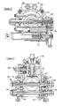
- the first gear arrangement 30 is illustrated in more detail in Figure 3 and comprises a housing 42 within which a pinion gear 44 is supported for rotation through bearings 46.
- the pinion gear 44 is coupled directly to an output shaft 32 of the motor 10 as shown in Figure 1 .
- the pinion gear 44 is illustrated as being accessible from both sides of the housing 42 in use the access opening remote from the shaft 32 will be closed, the provision of two access openings permitting the actuator to have the motor located on either side thereof.
- the pinion gear 44 includes a series of teeth arranged to mesh with the teeth of a face gear 50 which, in turn, referring back to Figure 1 , is connected to the shaft 34 and so is operatively connected to the nut 20. It will be appreciated, therefore, that rotation of the pinion gear 44 by the motor 10 drives the face gear 50 and shaft 34 for rotation, thereby driving the shaft 22 for axial movement.
- the pinion gear 44 in addition to serving to drive the face gear 50 and nut 20 for rotation, also meshingly engages an output gear 52 supported by bearings 54 within the housing 42.
- the output gear 52 is of double-ended form, each end 56 of the gear 52 being arranged to be coupled to a respective one of the flexible drive shafts 36.
- the gear arrangement 30 further comprises a manual drive arrangement 58 whereby the face gear 50 can be driven for rotation independently of the motor 10, and a lock arrangement 60 whereby the face gear 50, and hence actuator 12 can be locked against movement with the actuator 12 in substantially any position.
- a no-back device 61 (see Figure 1 ) is provided to apply a braking load resisting movement of the actuator as a result of the application of external loads to the cowl 18.
- the second gear arrangement 38 is illustrated in greater detail in Figure 2 and, like the first gear arrangement 30, comprises a pinion gear 62 supported for rotation within a housing 64 and arranged to be driven for rotation by the drive shaft 36 (see Figure 1 ).
- the pinion gear 62 meshes with a face gear 66 coupled to a drive shaft 68 rotatable to drive the nut 20 of the second actuator 14 for rotation.
- the second gear arrangement 38 further drives a gear train 70 which in turn drives an LVDT 72 to provide an indication of the position occupied by the second actuator 14.
- the gear train 70 is made up of gears of a plastics material.
- plastics materials are advantageous in that they are of low weight. In prior arrangements, the use of such plastics materials would not have been possible as the plastics components would have been attacked by the lubricant materials, for example Skydrol ®, used in the gear arrangement.
- the gear train 70 is very lightly loaded thus the risk of damage to the gears making up the gear train 70, in use, is low. Rather than use an LVDT 72, an RVDT sensor driven by a reduction gear arrangement may be used.
- the second gear arrangement 38 and/or second actuator 14 will have proximity switches 74, a manual release 76 and a primary lock arrangement 78 associated therewith for use in controlling operation of the thrust reverser system. Further, like the actuator 12, a no-back device 79 is provided.
- the third gear arrangement 40 is of very similar form to the second gear arrangement 38, but omits the gear train 70 and LVDT 72.
- the motor 10 is controlled by a control unit 80 which, as illustrated, receives position and locks status information from the sensors 74, LVDT 72 and sensors 82 associated with the track along which the cowl 18 is guided for movement.
- the control unit 80 further controls operation of the primary locks 78 and a lock 84 associated with the track.
- the control unit 80 instructs the locks to release, and release of the locks is sensed by the sensors 74, 82.
- the motor 10 is driven for rotation.
- the operation of the motor 10 results in the output shaft 32 thereof rotating, driving the first gear arrangement 30 for rotation.
- the first gear arrangement 30 serves to drive the first actuator 12 for extension and also drives the flexible drive shafts 36 for rotation.
- the flexible drive shafts 36 drive the second and third gear arrangements 38, 40 for rotation which, in turn drives the second and third actuators 14, 16. It will thus be appreciated that the operation of the motor 10 drives the three actuators 12, 14, 16 which in turn drives the thrust reverser cowl 18. Return movement of the cowl 18 is achieved by rotation of the motor 10 in the reverse direction.
- the first, second and third gear arrangements 30, 38, 40 are all dry running gear arrangements.
- the housings 42, 64 within which the pinion gears 44, 62 and face gears 50, 66 are supported for rotation are free of lubricant.
- the flexible drive shafts 36 are of dry running form.
- the flexible drive shafts 36 conveniently take the form of flexible drive shafts located within PTFE liners which support the drive shafts 36 for rotation without requiring the provision of fluid lubricants.
- the provision of dry running flexible drive shafts 36 is advantageous in that the low temperature viscosity drag effects are avoided and the weight of the lubricant is saved.
- the avoidance of the use of lubricants in the drive arrangement 26 further reduces maintenance and servicing operations in that servicing procedures to check that the correct levels of lubricant are present can be omitted and re-greasing operations are no longer required.
- the motor 10 is conveniently of dry running form using sealed-for-life bearings. As a consequence, servicing and maintenance of the motor is also reduced.
- the drive shafts and the gear arrangements of the drive transmission arrangement are dry-running with the result that the drive transmission arrangement as a whole is a dry-running drive transmission arrangement
- one or other of the drive shaft(s) and the gear arrangement may be lubricated, preferably only lightly, whilst still achieving at least some of the benefits of the invention.
Landscapes
- Engineering & Computer Science (AREA)
- Chemical & Material Sciences (AREA)
- Combustion & Propulsion (AREA)
- Mechanical Engineering (AREA)
- General Engineering & Computer Science (AREA)
- Connection Of Motors, Electrical Generators, Mechanical Devices, And The Like (AREA)
- Gear Transmission (AREA)
Abstract
Description
- This invention relates to an actuator system for use in aerospace applications, and in particular to an electrically powered thrust reverser actuator system.
- A typical thrust reverser system includes a number of movable components which are each arranged to be driven, in use, between a stowed position and a deployed position. Many systems are known in which hydraulic actuators are used to drive the movable components between these positions. Such systems are typically heavy. The need to route pipework from the associated hydraulic pumps to the actuators results in the systems being of relatively complex form, and adds extra weight to the system.
- It is desired to use electrically powered actuators to drive the movable thrust reverser components, and
US 5960626 describes a scheme of this type. Such a scheme makes use of a series of linear screw actuators, each of which has a motor associated therewith. As a thrust reverser system associated with an engine will usually include several, for example four or six, actuators, it will be appreciated that the weight of the actuators and their associated motors is significant. - It is known to use a single motor to drive several actuators. For example
US 4522358 describes an arrangement in which a single hydraulic motor is used to drive several actuators, flexible drive shafts and gearboxes being used in the transmission of power to the actuators. - The primary use of a thrust reverser system is in deceleration of an aircraft on landing, thus the actuators will typically have spent a significant period of time in a low temperature environment, for example at temperatures below -50°C, shortly before use. At such temperatures, the lubricants used in bearings, gearboxes or the like typically become highly viscous and as a result the motor used to drive each actuator has to be capable of overcoming the drag loadings resulting from the increased viscosity of the lubricants. Where hydraulically powered linear actuators are used, sufficient excess power is usually present that overcoming the drag loadings can be readily achieved. However, where an electric motor is used, a motor of increased power may be required. Higher power motors are typically of increased size and weight, resulting in consequent increases in the associated structures and, additionally, the components driven by the higher power capability need to be larger and heavier in order to resist damage from the potentially greater loads. This is undesirable.
- The effect of increased lubricant drag is particularly critical where the drag is applied at or upstream of a gearbox in which the relatively high speed, low torque output of the motor is converted to a lower rotary speed, higher torque input to the actuator.
- In addition to causing drag, especially at low temperatures, extra maintenance operations due to the presence of the lubricants, for example checking and re-greasing the gearbox and associated shafts, have to be undertaken. Further, the presence of the lubricants adds additional weight to the system.
- It is an object of the invention to provide an actuator system, and in particular a thrust reverser actuator system, in which at least some of the disadvantages set out hereinbefore are overcome or are of reduced effect.
- According to the present invention there is provided an actuator system comprising an electric motor, a plurality of linearly extendable actuators, and a drive transmission arrangement transmitting rotary drive from the motor to the actuators, wherein the drive transmission arrangement includes a drive shaft and a gear arrangement, and wherein at least one of the drive shaft and the gear arrangement is dry-running.
- The actuator system is preferably a thrust reverser actuator system in which the linearly extendable actuators are operable to drive part of a thrust reverser system for movement.
- Where the drive shaft is dry-running then the gear arrangement may be lightly lubricated. Alternatively, the entire drive transmission arrangement may be a dry-running drive transmission arrangement.
- By providing a dry-running, or substantially dry-running, drive transmission arrangement, that is to say a drive transmission arrangement in which little or no fluid lubricant is used, or avoiding the use of fluid lubricants in at least one of the drive shaft and the gear arrangement of the drive transmission arrangement, it will be appreciated that the low temperature viscosity issues mentioned hereinbefore are reduced or overcome, maintenance operations are reduced or eliminated, and the weight of the lubricant is saved.
- Preferably dry running flexible drive shafts are used to transmit drive to at least one of the actuators.
- Each actuator conveniently has a dry-running gear arrangement associated therewith forming part of the drive transmission arrangement. The dry-running gear arrangements each preferably comprise a pinion gear and a face gear in meshing engagement with one another.
- The motor is preferably a dry-running motor with sealed-for-life bearings.
- The motor output is preferably connected directly to the gear arrangement of a first one of the actuators, although this need not always be the case and arrangements in which the motor output is connected to the gear arrangement by, for example, a flexible drive shaft are also possible. As a result, the provision of a motor output gearbox within the motor housing can be avoided, reducing weight and avoiding the need for additional lubrication. The gear arrangement of the first one of the actuators is preferably further operable to drive an output whereby rotary drive can be transmitted to at least a second one of actuators. The output is preferably double ended.
- The second actuator preferably has a position sensor associated therewith for monitoring the position of the actuators.
- The position sensor is preferably an LVDT driven by a plastics material gearing arrangement. The use of such a plastics material gearing arrangement is advantageous in that it is of relatively low weight. Alternatively, the position sensor may be an RVDT sensor driven by a reduction gearbox.
- The invention will further be described, by way of example, with reference to the accompanying drawings, in which:
-
Figure 1 is a schematic view illustrating a thrust reverser actuator system in accordance with an embodiment of the invention; and -
Figures 2 and 3 are views illustrating the gear arrangements of two of the actuators of the system shown inFigure 1 . - The thrust reverser actuator system illustrated in
Figure 1 comprises an electrically poweredmotor 10 arranged to drive three linearlyextendible actuators thrust reverser cowl 18. Eachactuator rotatable nut component 20 which is in threaded engagement with anoutput shaft 22, the nature of the threaded engagement between thenut component 20 at theshaft 22 being of a low friction form, for example comprising a roller or ball-screw coupling. Theshafts 22 are mounted to thethrust reverser cowl 18, the nature of the mountings being such that theshafts 22 are held against rotation. It will be appreciated that in such an arrangement rotation of eachnut component 20 causes the associatedshaft 22 to translate, thereby driving thethrust reverser cowl 18 between its stowed and deployed positions. - Each
nut 20 is secured torotatable drive tube 24 arranged to be driven for rotation by themotor 10 through adrive transmission arrangement 26.Stops 28 are mounted upon the ends of theshafts 22 of the second andthird actuators stops 28 and thenuts 20 when theactuators cowl 18. - The
drive transmission arrangement 26 comprises afirst gear arrangement 30 arranged to be driven for rotation by themotor 10. Thefirst gear arrangement 30 includes adrive output 34 operable to drive thenut 20 of thefirst actuator 12 for rotation. Thefirst gear arrangement 30 is further arranged to drive a pair offlexible drive shafts 36 for rotation. Theflexible drive shafts 36 are operable to drive second andthird gear arrangements third actuators gear arrangements drive shafts 36 form part of thedrive transmission arrangement 26. - The
first gear arrangement 30 is illustrated in more detail inFigure 3 and comprises ahousing 42 within which apinion gear 44 is supported for rotation throughbearings 46. Thepinion gear 44 is coupled directly to anoutput shaft 32 of themotor 10 as shown inFigure 1 . Although thepinion gear 44 is illustrated as being accessible from both sides of thehousing 42 in use the access opening remote from theshaft 32 will be closed, the provision of two access openings permitting the actuator to have the motor located on either side thereof. - The
pinion gear 44 includes a series of teeth arranged to mesh with the teeth of aface gear 50 which, in turn, referring back toFigure 1 , is connected to theshaft 34 and so is operatively connected to thenut 20. It will be appreciated, therefore, that rotation of thepinion gear 44 by themotor 10 drives theface gear 50 andshaft 34 for rotation, thereby driving theshaft 22 for axial movement. - The
pinion gear 44 in addition to serving to drive theface gear 50 andnut 20 for rotation, also meshingly engages anoutput gear 52 supported bybearings 54 within thehousing 42. Theoutput gear 52 is of double-ended form, eachend 56 of thegear 52 being arranged to be coupled to a respective one of theflexible drive shafts 36. - The
gear arrangement 30 further comprises amanual drive arrangement 58 whereby theface gear 50 can be driven for rotation independently of themotor 10, and alock arrangement 60 whereby theface gear 50, and henceactuator 12 can be locked against movement with theactuator 12 in substantially any position. A no-back device 61 (seeFigure 1 ) is provided to apply a braking load resisting movement of the actuator as a result of the application of external loads to thecowl 18. - The
second gear arrangement 38 is illustrated in greater detail inFigure 2 and, like thefirst gear arrangement 30, comprises apinion gear 62 supported for rotation within ahousing 64 and arranged to be driven for rotation by the drive shaft 36 (seeFigure 1 ). Thepinion gear 62 meshes with aface gear 66 coupled to adrive shaft 68 rotatable to drive thenut 20 of thesecond actuator 14 for rotation. - It will be appreciated that in use operation of the
motor 10 not only serves to drive theactuator 12, but also drives theflexible drive shaft 36 for rotation by virtue of the operation of thefirst gear arrangement 30, and thesecond gear arrangement 38 which is driven by thedrive shaft 36 drives thesecond actuator 14 for movement. - In addition to driving the
second actuator 14 for movement, thesecond gear arrangement 38 further drives agear train 70 which in turn drives an LVDT 72 to provide an indication of the position occupied by thesecond actuator 14. Thegear train 70 is made up of gears of a plastics material. The use of plastics materials is advantageous in that they are of low weight. In prior arrangements, the use of such plastics materials would not have been possible as the plastics components would have been attacked by the lubricant materials, for example Skydrol ®, used in the gear arrangement. Thegear train 70 is very lightly loaded thus the risk of damage to the gears making up thegear train 70, in use, is low. Rather than use anLVDT 72, an RVDT sensor driven by a reduction gear arrangement may be used. - Although not illustrated in
Figure 2 , thesecond gear arrangement 38 and/orsecond actuator 14 will have proximity switches 74, amanual release 76 and aprimary lock arrangement 78 associated therewith for use in controlling operation of the thrust reverser system. Further, like theactuator 12, a no-back device 79 is provided. - The
third gear arrangement 40 is of very similar form to thesecond gear arrangement 38, but omits thegear train 70 andLVDT 72. - The
motor 10 is controlled by acontrol unit 80 which, as illustrated, receives position and locks status information from thesensors 74,LVDT 72 andsensors 82 associated with the track along which thecowl 18 is guided for movement. Thecontrol unit 80 further controls operation of theprimary locks 78 and alock 84 associated with the track. When it is desired to deploy the thrust reverser, thecontrol unit 80 instructs the locks to release, and release of the locks is sensed by thesensors control unit 80 is satisfied that the locks have been released, themotor 10 is driven for rotation. The operation of themotor 10 results in theoutput shaft 32 thereof rotating, driving thefirst gear arrangement 30 for rotation. Thefirst gear arrangement 30 serves to drive thefirst actuator 12 for extension and also drives theflexible drive shafts 36 for rotation. Theflexible drive shafts 36 drive the second andthird gear arrangements third actuators motor 10 drives the threeactuators thrust reverser cowl 18. Return movement of thecowl 18 is achieved by rotation of themotor 10 in the reverse direction. - In accordance with the invention, the first, second and
third gear arrangements housings housings - Not only are the first, second and
third gear arrangements flexible drive shafts 36 are of dry running form. Theflexible drive shafts 36 conveniently take the form of flexible drive shafts located within PTFE liners which support thedrive shafts 36 for rotation without requiring the provision of fluid lubricants. As with the gear arrangements, the provision of dry runningflexible drive shafts 36 is advantageous in that the low temperature viscosity drag effects are avoided and the weight of the lubricant is saved. - It will be apparent from the description hereinbefore that the entire drive arrangement whereby drive is transmitted from the
motor 10 to the threeactuators - Further savings are achieved by avoiding the provision of a gearbox between the output of the
motor 10 and thefirst gear arrangement 30, instead having thedrive output 32 of themotor 10 connected directly to thefirst gear arrangement 30. As a result, not only is the weight of such a gearbox saved but also the provision of lubricant therein and the low temperature viscosity drag effects of such lubricant is avoided. - In addition to the weight savings achievable by avoiding the use of lubricants and the low temperature viscosity issues mentioned hereinbefore being overcome, the avoidance of the use of lubricants in the
drive arrangement 26 further reduces maintenance and servicing operations in that servicing procedures to check that the correct levels of lubricant are present can be omitted and re-greasing operations are no longer required. - As well as providing a dry running drive arrangement, the
motor 10 is conveniently of dry running form using sealed-for-life bearings. As a consequence, servicing and maintenance of the motor is also reduced. - Although in the arrangement described hereinbefore the drive shafts and the gear arrangements of the drive transmission arrangement are dry-running with the result that the drive transmission arrangement as a whole is a dry-running drive transmission arrangement, one or other of the drive shaft(s) and the gear arrangement may be lubricated, preferably only lightly, whilst still achieving at least some of the benefits of the invention.
- The description hereinbefore relates primarily to the use of the invention in connection with a thrust reverser system. It will be appreciated, however, that the actuator system of the invention may be used in other applications, for example in the actuation or movement of flight control surfaces.
- It will be appreciated that a wide range of modifications and alterations may be made to the arrangement described hereinbefore without departing from the scope of the invention.
Claims (12)
- An actuator system comprising an electric motor (10), a plurality of linearly extendable actuators (12, 14, 16), and a drive transmission arrangement (26) transmitting rotary drive from the motor (10) to the actuators (12, 14, 16), wherein the drive transmission arrangement (26) includes a drive shaft (36) and a gear arrangement (30, 38, 40), and wherein at least one of the drive shaft (36) and the gear arrangement (30, 38, 40) is dry-running.
- A system according to Claim 1, wherein the system is a thrust reverser actuator system.
- A system according to Claim 1 or Claim 2, wherein the drive shaft (36) is dry-running and the gear arrangement (30, 38, 40) is lightly lubricated.
- A system according to Claim 1 or Claim 2, wherein the entire drive transmission arrangement (26) is a dry-running drive transmission arrangement.
- A system according to any of the preceding claims, wherein at least one dry running flexible drive shaft (36) is used to transmit drive to at least one of the actuators (12, 14, 16).
- A system according to any of the preceding claims, wherein each actuator (12, 14, 16) has a dry-running gear arrangement (30, 38, 40) associated therewith forming part of the drive transmission arrangement (26).
- A system according to Claim 5, wherein the dry-running gear arrangements (30, 38, 40) each comprise a pinion gear (44) and a face gear (50) in meshing engagement with one another.
- A system according to any of the preceding claims, wherein the motor (10) is a dry-running motor with sealed-for-life bearings.
- A system according to any of the preceding claims wherein the motor output is connected directly to the gear arrangement (30) of a first one of the actuators (12), the gear arrangement (30) of the first one of the actuators (12) being further operable to drive an output whereby rotary drive can be transmitted to at least a second one of actuators (14).
- A system according to Claim 9, wherein the second actuator (14) has a position sensor (72) associated therewith for monitoring the position of the actuators.
- A system according to Claim 10, wherein the position sensor (72) is an LVDT driven by a plastics material gearing arrangement (70).
- A system according to Claim 10, wherein the position sensor is an RVDT sensor driven by a reduction gearbox.
Applications Claiming Priority (1)
| Application Number | Priority Date | Filing Date | Title |
|---|---|---|---|
| GBGB0906392.6A GB0906392D0 (en) | 2009-04-15 | 2009-04-15 | Thrust reverser actuator system |
Publications (2)
| Publication Number | Publication Date |
|---|---|
| EP2243946A2 true EP2243946A2 (en) | 2010-10-27 |
| EP2243946A3 EP2243946A3 (en) | 2012-07-11 |
Family
ID=40750559
Family Applications (1)
| Application Number | Title | Priority Date | Filing Date |
|---|---|---|---|
| EP10250765A Withdrawn EP2243946A3 (en) | 2009-04-15 | 2010-04-13 | Actuators system |
Country Status (3)
| Country | Link |
|---|---|
| US (1) | US20110094324A1 (en) |
| EP (1) | EP2243946A3 (en) |
| GB (1) | GB0906392D0 (en) |
Families Citing this family (2)
| Publication number | Priority date | Publication date | Assignee | Title |
|---|---|---|---|---|
| FR2974597B1 (en) * | 2011-04-27 | 2019-05-10 | Safran Nacelles | TERTIARY LATCH ASSEMBLY FOR THRUST REVERSING DEVICE |
| US11781502B2 (en) * | 2020-05-05 | 2023-10-10 | Rohr, Inc. | Actuation system for a thrust reverser of an aircraft propulsion system |
Citations (2)
| Publication number | Priority date | Publication date | Assignee | Title |
|---|---|---|---|---|
| US4522358A (en) | 1982-06-16 | 1985-06-11 | Mtu | Method and apparatus for the displacement of two thrust reversers of jet engines of an aircraft in synchronism during the thrust reversal phase |
| US5960626A (en) | 1996-11-14 | 1999-10-05 | Societe Hispano Suiza | Electric control system for a turbojet engine thrust reverser including an electromechanical drive device and a locking device which are controlled by an electronic control unit |
Family Cites Families (20)
| Publication number | Priority date | Publication date | Assignee | Title |
|---|---|---|---|---|
| US3637497A (en) * | 1968-06-12 | 1972-01-25 | Us Navy | Moisture resistant dry film lubricants |
| US3922852A (en) * | 1973-10-17 | 1975-12-02 | Gen Electric | Variable pitch fan for gas turbine engine |
| US4813303A (en) * | 1984-08-31 | 1989-03-21 | Mandreles, Inc. | Power drive speed reducer |
| US5178028A (en) * | 1990-09-27 | 1993-01-12 | Lucas Western, Inc. | Offset face gear transmission |
| GB2324843B (en) * | 1996-02-15 | 2000-05-17 | Kelsy Hayes Company | Brake actuation mechanism |
| FR2760047B1 (en) * | 1997-02-27 | 1999-05-07 | Hispano Suiza Sa | TURBOJET DRIVE INVERTER WITH DOORS ASSOCIATED WITH A CONTROL SYNCHRONIZATION DEVICE |
| US5974911A (en) * | 1998-06-16 | 1999-11-02 | Fiatavio S.P.A. | Face-gear transmission assembly with floating balance pinions |
| IT1303140B1 (en) * | 1998-10-16 | 2000-10-30 | Fiatavio Spa | TRANSMISSION WITH FACIAL GEARS, ESPECIALLY FOR AIRCRAFT APPLICATIONS. |
| IT1303139B1 (en) * | 1998-10-16 | 2000-10-30 | Fiatavio Spa | FACIAL GEAR TRANSMISSION GROUP, PARTICULARLY FOR AERONAUTICAL APPLICATIONS. |
| US6786315B1 (en) * | 2003-03-28 | 2004-09-07 | Honeywell International, Inc. | Thrust reverser system with sequential torque decoupler |
| US6974107B2 (en) * | 2003-06-18 | 2005-12-13 | Honeywell International, Inc. | Thrust reverser system actuator having an integral torque limiter |
| US6827310B1 (en) * | 2003-09-22 | 2004-12-07 | The United States Of America As Represented By The Secretary Of The Navy | Apparatus and method for fin actuation in a portable missile |
| GB0421568D0 (en) * | 2004-09-29 | 2004-10-27 | Smiths Group Plc | Drive assemblies |
| US7435180B2 (en) * | 2005-01-10 | 2008-10-14 | Honeywell International Inc. | Thrust reverser actuator system flex shaft assembly |
| FR2881183B1 (en) * | 2005-01-21 | 2007-04-06 | Hurel Hispano Sa | METHOD FOR FASTENING A FLEXIBLE TRANSMISSION SHAFT IN A PUSH REVIER |
| JP4902534B2 (en) * | 2005-05-25 | 2012-03-21 | 旭有機材工業株式会社 | Resin gear for electric power steering apparatus and electric power steering apparatus provided with the same |
| EP1959167B1 (en) * | 2007-02-19 | 2012-06-06 | Enplas Corporation | Injection-molded resin face gear |
| GB0705301D0 (en) * | 2007-03-20 | 2007-04-25 | Goodrich Actuation Systems Ltd | Actuator arrangement |
| GB0706270D0 (en) * | 2007-03-30 | 2007-05-09 | Goodrich Actuation Systems Ltd | Actuator arrangement |
| GB0706524D0 (en) * | 2007-04-04 | 2007-05-09 | Goodrich Actuation Systems Ltd | Actuator arrangement |
-
2009
- 2009-04-15 GB GBGB0906392.6A patent/GB0906392D0/en not_active Ceased
-
2010
- 2010-04-13 EP EP10250765A patent/EP2243946A3/en not_active Withdrawn
- 2010-04-14 US US12/759,975 patent/US20110094324A1/en not_active Abandoned
Patent Citations (2)
| Publication number | Priority date | Publication date | Assignee | Title |
|---|---|---|---|---|
| US4522358A (en) | 1982-06-16 | 1985-06-11 | Mtu | Method and apparatus for the displacement of two thrust reversers of jet engines of an aircraft in synchronism during the thrust reversal phase |
| US5960626A (en) | 1996-11-14 | 1999-10-05 | Societe Hispano Suiza | Electric control system for a turbojet engine thrust reverser including an electromechanical drive device and a locking device which are controlled by an electronic control unit |
Also Published As
| Publication number | Publication date |
|---|---|
| EP2243946A3 (en) | 2012-07-11 |
| US20110094324A1 (en) | 2011-04-28 |
| GB0906392D0 (en) | 2009-05-20 |
Similar Documents
| Publication | Publication Date | Title |
|---|---|---|
| EP2169204B1 (en) | Actuator | |
| US10066715B2 (en) | Fail-safe electromechanical actuator | |
| EP2048413A1 (en) | Actuator arrangement | |
| EP1978233B1 (en) | Actuator arrangement for a thrust reverser | |
| EP2626593B1 (en) | Electro mechanical actuator | |
| US9021903B2 (en) | Linear actuator | |
| EP2311731B1 (en) | Thrust reverser actuation | |
| EP3480116B1 (en) | Electro-mechanical actuator systems for opening and closing of aircraft engine cowl doors | |
| US11498658B2 (en) | System for an aircraft wing | |
| EP2728153B1 (en) | Actuator arrangement | |
| EP2280194A1 (en) | Rotary actuator | |
| EP3613667B1 (en) | Linear actuator with testable cone no-back and torque limiter | |
| IT201900018305A1 (en) | ROTARY SCREW MECHANICAL TRANSMISSION | |
| IT201900018308A1 (en) | LINEAR SCREW MECHANICAL TRANSMISSION | |
| US9016151B2 (en) | High integrity linear actuator and method of operation | |
| EP1731421A1 (en) | Electro-mechanical linear actuator | |
| EP2243946A2 (en) | Actuators system | |
| EP2993375A1 (en) | Gearbox with reduced backlash | |
| US20250146563A1 (en) | Fault tolerant rotary ema | |
| EP3038907B1 (en) | Multi-plate clutch | |
| EP4474668B1 (en) | Clutch/brake assembly | |
| IT202200020739A1 (en) | Rotary mechanical transmission |
Legal Events
| Date | Code | Title | Description |
|---|---|---|---|
| PUAI | Public reference made under article 153(3) epc to a published international application that has entered the european phase |
Free format text: ORIGINAL CODE: 0009012 |
|
| AK | Designated contracting states |
Kind code of ref document: A2 Designated state(s): AT BE BG CH CY CZ DE DK EE ES FI FR GB GR HR HU IE IS IT LI LT LU LV MC MK MT NL NO PL PT RO SE SI SK SM TR |
|
| AX | Request for extension of the european patent |
Extension state: AL BA ME RS |
|
| PUAL | Search report despatched |
Free format text: ORIGINAL CODE: 0009013 |
|
| AK | Designated contracting states |
Kind code of ref document: A3 Designated state(s): AT BE BG CH CY CZ DE DK EE ES FI FR GB GR HR HU IE IS IT LI LT LU LV MC MK MT NL NO PL PT RO SE SI SK SM TR |
|
| AX | Request for extension of the european patent |
Extension state: AL BA ME RS |
|
| RIC1 | Information provided on ipc code assigned before grant |
Ipc: F02K 1/76 20060101AFI20120601BHEP Ipc: F16H 25/20 20060101ALI20120601BHEP Ipc: F16H 57/04 20100101ALI20120601BHEP |
|
| STAA | Information on the status of an ep patent application or granted ep patent |
Free format text: STATUS: THE APPLICATION IS DEEMED TO BE WITHDRAWN |
|
| 18D | Application deemed to be withdrawn |
Effective date: 20130112 |