EP2243931A2 - Turbine casing cooling - Google Patents
Turbine casing cooling Download PDFInfo
- Publication number
- EP2243931A2 EP2243931A2 EP10156605A EP10156605A EP2243931A2 EP 2243931 A2 EP2243931 A2 EP 2243931A2 EP 10156605 A EP10156605 A EP 10156605A EP 10156605 A EP10156605 A EP 10156605A EP 2243931 A2 EP2243931 A2 EP 2243931A2
- Authority
- EP
- European Patent Office
- Prior art keywords
- casing
- cooling
- manifold
- turbine
- dummy
- Prior art date
- Legal status (The legal status is an assumption and is not a legal conclusion. Google has not performed a legal analysis and makes no representation as to the accuracy of the status listed.)
- Withdrawn
Links
- 238000001816 cooling Methods 0.000 title claims abstract description 46
- 125000006850 spacer group Chemical group 0.000 claims description 6
- 230000000694 effects Effects 0.000 description 3
- 238000011144 upstream manufacturing Methods 0.000 description 2
- 238000007664 blowing Methods 0.000 description 1
- 230000001419 dependent effect Effects 0.000 description 1
- 238000011161 development Methods 0.000 description 1
- 230000018109 developmental process Effects 0.000 description 1
- 238000006073 displacement reaction Methods 0.000 description 1
- 239000000446 fuel Substances 0.000 description 1
Images


Classifications
-
- F—MECHANICAL ENGINEERING; LIGHTING; HEATING; WEAPONS; BLASTING
- F01—MACHINES OR ENGINES IN GENERAL; ENGINE PLANTS IN GENERAL; STEAM ENGINES
- F01D—NON-POSITIVE DISPLACEMENT MACHINES OR ENGINES, e.g. STEAM TURBINES
- F01D11/00—Preventing or minimising internal leakage of working-fluid, e.g. between stages
- F01D11/08—Preventing or minimising internal leakage of working-fluid, e.g. between stages for sealing space between rotor blade tips and stator
- F01D11/14—Adjusting or regulating tip-clearance, i.e. distance between rotor-blade tips and stator casing
- F01D11/20—Actively adjusting tip-clearance
- F01D11/24—Actively adjusting tip-clearance by selectively cooling-heating stator or rotor components
-
- F—MECHANICAL ENGINEERING; LIGHTING; HEATING; WEAPONS; BLASTING
- F01—MACHINES OR ENGINES IN GENERAL; ENGINE PLANTS IN GENERAL; STEAM ENGINES
- F01D—NON-POSITIVE DISPLACEMENT MACHINES OR ENGINES, e.g. STEAM TURBINES
- F01D25/00—Component parts, details, or accessories, not provided for in, or of interest apart from, other groups
- F01D25/08—Cooling; Heating; Heat-insulation
- F01D25/14—Casings modified therefor
-
- F—MECHANICAL ENGINEERING; LIGHTING; HEATING; WEAPONS; BLASTING
- F05—INDEXING SCHEMES RELATING TO ENGINES OR PUMPS IN VARIOUS SUBCLASSES OF CLASSES F01-F04
- F05D—INDEXING SCHEME FOR ASPECTS RELATING TO NON-POSITIVE-DISPLACEMENT MACHINES OR ENGINES, GAS-TURBINES OR JET-PROPULSION PLANTS
- F05D2260/00—Function
- F05D2260/20—Heat transfer, e.g. cooling
- F05D2260/201—Heat transfer, e.g. cooling by impingement of a fluid
Definitions
- the present invention relates to turbine casing cooling, for example in gas turbine engines.
- FIGs 1A and 1B illustrate a prior cooling manifold A, which in use is wrapped around an engine (not shown), and air blows onto engine casings (not shown) through a series of small holes 4 shown best in the enlarged detail of Figure 1B .
- Air is supplied/discharged via a manifold iniet/outiet defined inter alia by flanges 2 and 3.
- Bolt holes 1 provide for mounting of the manifold.
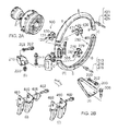
- FIG. 2A schematically illustrates a possible positioning of a cooling manifold A in relation to the casing and the rest of an engine.
- the manifold A is attached to the engine via brackets and fastening means:- see B, C, D, E in Figure 2A , see also items 085, 100, 129, 130 131, 200, 202, 203, 206, 215, 217, 218, 220, 250, 273, 274, 275, 278, 279, 281, 400, 423, 424, 425, 429, 430, 431, 486, 489, 490, 492, (see also bolt holes 1 in Figure 1A , which inter alia connect the manifold to the casing mounting flanges upstream and downstream).
- Flanges 2 and 3 (see eg Figure 1B ) on the manifold define inlet/outlet ducting for air supplied to the manifold A.
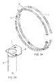
- Manifold tubes 1 have a series of inward facing holes 5, best seen in the enlarged detail of Figure 3B , and blow air directly onto the casing surrounded by the manifold/tubes.
- the tubes are provided with anti-frettage liners 2 and assembly bolt holes 3 provided in flanges 4 for attachment of the tubes to inlet/outlet ducting (not shown).
- This tube arrangement is attached to the engine via clips (not shown) mounted off brackets (not shown), which are in turn are mounted off adjacent casing mounting flanges (not shown).
- casings may be provided with external dummy flanges/extensions designed to provide a larger area to increase the cooling effect and to stiffen the casing in the circumferential direction.
- the inventor has had the insight that dummy flanges, as opposed to casing mounting flanges, can be exploited to provide for better control of the radial distance between manifold and casing, and better axial positioning, which can lead to more even and higher cooling rates and thus an improved casing cooling arrangement
- a turbine assembly having a bladed turbine wheel and a turbine casing, extending axially of the turbine assembly, radially outwardly surrounding the tips of the blades of the turbine wheel, the casing having at least one radially outwardly extending dummy flange off which, in axial direction, one or more cooling manifolds, wrapping radially outwardly around the casing, are mounted, the or each cooling manifold being adapted to receive cooling air and to discharge the cooling air radially inwardly towards the casing, for cooling the casing.
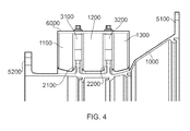
- three casing cooling manifolds 1100, 1200 and 1300 are mounted directly off two dummy flanges 2100, 2200 provided on the casing 1000 of a turbine assembly, as best illustrated cross-section of Figure 4 .
- a dummy flange is a flange which plays no part in mounting the casing in the engine or other equipment of the turbine assembly.
- separate mounting flanges 5100, 5200 serve for mounting the casing in the engine or other equipment to surround the tips of turbine blades of a turbine wheel of the engine or other equipment.
- the cooling manifolds 1100, 1200 and 1300 receive cooling air at manifold inlets (not shown).
- the manifolds wrap around the casing and discharge cooling air onto the casing, by way of inwardly directed holes (not shown) in the manifolds (holes towards the casing) as in prior arrangements, or other inwardly directed discharge means such as slits or slots for example. Excess air can be released through a manifold outlet (not shown) for example as in prior arrangements.
- the left (in Figure 4 ) and right (in Figure 4 ) dummy flanges 2100, 2200 are shown as having the same dimensions in the illustrated embodiment. In other embodiments of the invention the dummy flanges may have different dimensions as appropriate or necessary for design reasons.
- each of the dummy flanges 2100, 2200 there is a mounting feature 3100, 3200.
- These mounting features are arranged around and can be considered to be parts of the dummy flanges as best illustrated in Figure 4 or in the perspective view of Figure 6 which shows the casing with manifold removed for clarity.
- Figure 6 the right hand mounting feature is cut away to show a bolt to fix the manifold onto a threaded insert within the mounting feature.
- both mounting features 3100, 3200 there is provided a spacer 6000 that can be used to control and alter the radial displacement of the manifold and therefore control the distance between manifold and casing, eg by using spacers of different thicknesses.
- the dummy flanges 2100, 2200 are not continuous around the casing 1000 but are provided intermittently around the casing 1000. This can provide for reduced weight. In other embodiments, however, the dummy flanges may be continuous around the casing.
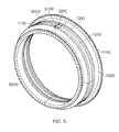
- the manifolds 1100, 1200, 1300 wrap around the casing 1000.
- This arrangement allows better control of the radial gap because the number of manufactured features involved is fewer and the distances are lower and less susceptible to thermal distortion.
- This invention allows changes to be made to the spacers 6000 to adjust the radial gap and thus alter the cooling.
- more or less than two dummy flanges may provided, continuously or intermittently, of the same or different dimensions when a plurality of dummy flanges are provided, and casing cooling manifolds may be mounted directly off all or only some of the dummy flanges.
- axial distances can also be controlled in a similar manner to ensure better control of cooling on the faces of the dummy flanges.
- spacers could be connected to the sides of the mounting features to control the axial gaps.
- axial and radial distances can be controlled better to give a more even and consistent cooling effect, and this independently of considerations or tolerances relating to mounting of the casing in the engine or other equipment.
- the tip clearance is better controlled and, for example, engine performance is enhanced for both new engines and in service/deteriorated engines.
- the present invention can offer mounting on dummy flanges in the area to be cooled and provide for axial and radial distances to be controlled better to give a more even and consistent cooling effect.
Landscapes
- Engineering & Computer Science (AREA)
- Mechanical Engineering (AREA)
- General Engineering & Computer Science (AREA)
- Turbine Rotor Nozzle Sealing (AREA)
Abstract
Description
- The present invention relates to turbine casing cooling, for example in gas turbine engines.
- In gas turbines engines it is necessary to control the clearances of the turbine blade tips from the turbine casing surrounding the tips, for example in order to minimise fuel consumption. This has been effected in various engines by using a shroud or cooling manifold placed circumferentially around the casing and blowing cold air onto the casing to reduce its diameter through reducing its temperature and thus limiting thermal expansion.
-
Figures 1A and 1B illustrate a prior cooling manifold A, which in use is wrapped around an engine (not shown), and air blows onto engine casings (not shown) through a series of small holes 4 shown best in the enlarged detail ofFigure 1B . Air is supplied/discharged via a manifold iniet/outiet defined inter alia byflanges - The synoptic view of
Figure 2A schematically illustrates a possible positioning of a cooling manifold A in relation to the casing and the rest of an engine. - As indicated in the exploded view of
Figure 2B the manifold A is attached to the engine via brackets and fastening means:- see B, C, D, E inFigure 2A , see alsoitems Figure 1A , which inter alia connect the manifold to the casing mounting flanges upstream and downstream).Flanges 2 and 3 (see egFigure 1B ) on the manifold define inlet/outlet ducting for air supplied to the manifold A. - A simpler prior version of a cooling manifold A is shown in
Figures 3A and 3B . Manifold tubes 1 have a series of inward facingholes 5, best seen in the enlarged detail ofFigure 3B , and blow air directly onto the casing surrounded by the manifold/tubes. The tubes are provided withanti-frettage liners 2 andassembly bolt holes 3 provided in flanges 4 for attachment of the tubes to inlet/outlet ducting (not shown). - This tube arrangement is attached to the engine via clips (not shown) mounted off brackets (not shown), which are in turn are mounted off adjacent casing mounting flanges (not shown).
- Apart from mounting flanges casings may be provided with external dummy flanges/extensions designed to provide a larger area to increase the cooling effect and to stiffen the casing in the circumferential direction.
- It has been found that prior cooling manifold arrangements provide for only poor control of the distance between manifold and casing which leads to uneven and low cooling rates. There is thus a need for an improved casing cooling arrangement.
- The inventor has had the insight that dummy flanges, as opposed to casing mounting flanges, can be exploited to provide for better control of the radial distance between manifold and casing, and better axial positioning, which can lead to more even and higher cooling rates and thus an improved casing cooling arrangement
- Thus, according to the present invention there is provided, in accordance with claim 1, a turbine assembly having a bladed turbine wheel and a turbine casing, extending axially of the turbine assembly, radially outwardly surrounding the tips of the blades of the turbine wheel, the casing having at least one radially outwardly extending dummy flange off which, in axial direction, one or more cooling manifolds, wrapping radially outwardly around the casing, are mounted, the or each cooling manifold being adapted to receive cooling air and to discharge the cooling air radially inwardly towards the casing, for cooling the casing.
- The dependent claims indicates advantageous developments and embodiments of the invention.
- In the accompanying drawings:-
-
Figure 1A shows a schematic perspective illustration of a prior casing cooling manifold; -
Figure 1B shows a detail ofFigure 1A to an enlarged scale; -
Figure 2A shows a schematic synoptic view illustrating a positioning of a casing cooling manifold in relation to the rest of a turbine engine; -
Figure 2B shows a schematic exploded view of a prior casing cooling manifold and related mounting parts; -
Figure 3A shows a schematic perspective illustration of a prior casing cooling manifold tube arrangement; -
Figure 3B shows a detail ofFigure 3A to an enlarged scale; -
Figure 4 shows a schematic cross-sectional view illustrating an embodiment of the present invention; -
Figure 5 shows a schematic perspective view illustrating the embodiment of the present invention; and -
Figure 6 shows a schematic perspective view illustrating the embodiment of the present invention with the casing cooling manifold removed. - In the illustrated embodiment, three
casing cooling manifolds dummy flanges casing 1000 of a turbine assembly, as best illustrated cross-section ofFigure 4 . A dummy flange is a flange which plays no part in mounting the casing in the engine or other equipment of the turbine assembly. In the illustrated embodimentseparate mounting flanges - The cooling manifolds 1100, 1200 and 1300 receive cooling air at manifold inlets (not shown). The manifolds wrap around the casing and discharge cooling air onto the casing, by way of inwardly directed holes (not shown) in the manifolds (holes towards the casing) as in prior arrangements, or other inwardly directed discharge means such as slits or slots for example. Excess air can be released through a manifold outlet (not shown) for example as in prior arrangements.
- The left (in
Figure 4 ) and right (inFigure 4 )dummy flanges - Above each of the
dummy flanges mounting feature Figure 4 or in the perspective view ofFigure 6 which shows the casing with manifold removed for clarity. InFigure 6 the right hand mounting feature is cut away to show a bolt to fix the manifold onto a threaded insert within the mounting feature. - Above both
mounting features spacer 6000 that can be used to control and alter the radial displacement of the manifold and therefore control the distance between manifold and casing, eg by using spacers of different thicknesses. - In the illustrated embodiment, the
dummy flanges casing 1000 but are provided intermittently around thecasing 1000. This can provide for reduced weight. In other embodiments, however, the dummy flanges may be continuous around the casing. - As best illustrated in the perspective view of
Figure 5
themanifolds casing 1000. - This arrangement allows better control of the radial gap because the number of manufactured features involved is fewer and the distances are lower and less susceptible to thermal distortion.
- This means that tight control of the casing/blade tip gap can be maintained on new engines and during service operations. In service, the engine deteriorates such that the tip clearances increase because the gas temperature increases and this leads to hotter & larger diameter casings. This invention allows changes to be made to the
spacers 6000 to adjust the radial gap and thus alter the cooling. - In other embodiments of the present invention more or less than two dummy flanges may provided, continuously or intermittently, of the same or different dimensions when a plurality of dummy flanges are provided, and casing cooling manifolds may be mounted directly off all or only some of the dummy flanges.
- Although not specifically illustrated, it should be noted that axial distances can also be controlled in a similar manner to ensure better control of cooling on the faces of the dummy flanges. For example spacers could be connected to the sides of the mounting features to control the axial gaps.
- Thus, in embodiments of the present invention axial and radial distances can be controlled better to give a more even and consistent cooling effect, and this independently of considerations or tolerances relating to mounting of the casing in the engine or other equipment. Thus the tip clearance is better controlled and, for example, engine performance is enhanced for both new engines and in service/deteriorated engines.
- In comparison with prior proposals, in which a cooling manifold is mounted off the (mounting) flanges upstream and/or downstream of an area to be cooled and build-up of tolerances and differential thermal expansion is considered to lead to poor control of impingement height, the present invention can offer mounting on dummy flanges in the area to be cooled and provide for axial and radial distances to be controlled better to give a more even and consistent cooling effect.
Claims (7)
- A turbine assembly having a bladed turbine wheel and a turbine casing (1000), extending axially of the turbine assembly, radially outwardly surrounding the tips of the blades of the turbine wheel, the casing having at least one radially outwardly extending dummy flange (2100, 2200) off which, in axial direction, one or more cooling manifolds (1100, 1200, 1300), wrapping radially outwardly around the casing, are mounted, the or each cooling manifold being adapted to receive cooling air and to discharge the cooling air radially inwardly towards the casing, for cooling the casing.
- A turbine assembly as claimed in claim 1, wherein a cooling manifold (1100, 1200, 1300) is mounted directly off a dummy flange (2100, 2200).
- A turbine assembly as claimed in claim 1, wherein a cooling manifold (1100, 1200, 1300) is mounted off a dummy flange (2100, 2200) with the interposition of an axial spacer, for adjusting the axial position of the manifold.
- A turbine assembly as claimed in any preceding claim, wherein a cooling manifold (1100, 1200, 1300) is mounted off a dummy flange (2100, 2200) with the radial interposition of a spacer (6000), for adjusting the radial position of the manifold.
- A turbine assembly as claimed in any preceding claim, having two dummy flanges (2100, 2200) off which three cooling manifolds (1100, 1200, 1300) are mounted, one (1200) axially between the dummy flanges, two (1100, 1300) axially outside the dummy flanges.
- A turbine assembly as claimed in any preceding claim, wherein the or each dummy flange (2100, 2200) is continuous around the casing (1000).
- A turbine assembly as claimed in any of claims 1 to 5, wherein the or each dummy flange (2100, 2200) is intermittent around the casing (1000).
Applications Claiming Priority (1)
| Application Number | Priority Date | Filing Date | Title |
|---|---|---|---|
| GB0906478.3A GB2469490B (en) | 2009-04-16 | 2009-04-16 | Turbine casing cooling |
Publications (2)
| Publication Number | Publication Date |
|---|---|
| EP2243931A2 true EP2243931A2 (en) | 2010-10-27 |
| EP2243931A3 EP2243931A3 (en) | 2013-09-18 |
Family
ID=40750633
Family Applications (1)
| Application Number | Title | Priority Date | Filing Date |
|---|---|---|---|
| EP10156605.7A Withdrawn EP2243931A3 (en) | 2009-04-16 | 2010-03-16 | Turbine casing cooling |
Country Status (3)
| Country | Link |
|---|---|
| US (1) | US8668438B2 (en) |
| EP (1) | EP2243931A3 (en) |
| GB (1) | GB2469490B (en) |
Cited By (5)
| Publication number | Priority date | Publication date | Assignee | Title |
|---|---|---|---|---|
| US8668438B2 (en) | 2009-04-16 | 2014-03-11 | Rolls-Royce Plc | Turbine casing cooling |
| FR3021700A1 (en) * | 2014-05-27 | 2015-12-04 | Snecma | DEVICE FOR MAINTAINING A COOLING TUBE FOR A TURBOJET CARTRIDGE |
| US9243513B2 (en) | 2010-12-02 | 2016-01-26 | Rolls-Royce Plc | Fluid impingement arrangement |
| FR3040428A1 (en) * | 2015-08-27 | 2017-03-03 | Snecma | DEVICE FOR COOLING AIR JETS OF THE CARTER OF A TURBINE OF A TURBOMACHINE |
| US10208626B2 (en) | 2010-08-17 | 2019-02-19 | Rolls-Royce Plc | Gas turbine manifold mounting arrangement including a clevis |
Families Citing this family (7)
| Publication number | Priority date | Publication date | Assignee | Title |
|---|---|---|---|---|
| US20130202420A1 (en) * | 2012-02-07 | 2013-08-08 | General Electric Company | Turbine Shell Having A Plate Frame Heat Exchanger |
| US9422824B2 (en) | 2012-10-18 | 2016-08-23 | General Electric Company | Gas turbine thermal control and related method |
| US9238971B2 (en) | 2012-10-18 | 2016-01-19 | General Electric Company | Gas turbine casing thermal control device |
| WO2014126961A1 (en) * | 2013-02-18 | 2014-08-21 | United Technologies Corporation | Cooling manifold for turbine section |
| US9869196B2 (en) * | 2014-06-24 | 2018-01-16 | General Electric Company | Gas turbine engine spring mounted manifold |
| US10914187B2 (en) * | 2017-09-11 | 2021-02-09 | Raytheon Technologies Corporation | Active clearance control system and manifold for gas turbine engine |
| KR102541933B1 (en) * | 2018-08-21 | 2023-06-13 | 지멘스 에너지 글로벌 게엠베하 운트 코. 카게 | Modular casing manifolds for cooling fluids in gas turbine engines |
Family Cites Families (19)
| Publication number | Priority date | Publication date | Assignee | Title |
|---|---|---|---|---|
| US2618461A (en) * | 1948-10-05 | 1952-11-18 | English Electric Co Ltd | Gas turbine |
| US3907458A (en) * | 1974-09-09 | 1975-09-23 | Gen Motors Corp | Turbomachine with evenly cooled turbine shroud |
| US4859142A (en) * | 1988-02-01 | 1989-08-22 | United Technologies Corporation | Turbine clearance control duct arrangement |
| FR2750451B1 (en) * | 1996-06-27 | 1998-08-07 | Snecma | DEVICE FOR BLOWING GAS ADJUSTING GAMES IN A TURBOMACHINE |
| GB9709086D0 (en) * | 1997-05-07 | 1997-06-25 | Rolls Royce Plc | Gas turbine engine cooling apparatus |
| FR2766231B1 (en) * | 1997-07-18 | 1999-08-20 | Snecma | CIRCULAR HOUSING HEATING OR COOLING DEVICE |
| US6185925B1 (en) * | 1999-02-12 | 2001-02-13 | General Electric Company | External cooling system for turbine frame |
| FR2816352B1 (en) * | 2000-11-09 | 2003-01-31 | Snecma Moteurs | VENTILATION ASSEMBLY OF A STATOR RING |
| US7108479B2 (en) * | 2003-06-19 | 2006-09-19 | General Electric Company | Methods and apparatus for supplying cooling fluid to turbine nozzles |
| FR2858652B1 (en) * | 2003-08-06 | 2006-02-10 | Snecma Moteurs | DEVICE FOR CONTROLLING PLAY IN A GAS TURBINE |
| FR2865237B1 (en) * | 2004-01-16 | 2006-03-10 | Snecma Moteurs | IMPROVEMENTS IN GAME CONTROL DEVICES IN A GAS TURBINE |
| FR2867806B1 (en) * | 2004-03-18 | 2006-06-02 | Snecma Moteurs | DEVICE FOR CONTROLLING GAS TURBINE SET WITH AIR FLOW BALANCING |
| GB0414043D0 (en) * | 2004-06-23 | 2004-07-28 | Rolls Royce Plc | Securing arrangement |
| US7246996B2 (en) * | 2005-01-04 | 2007-07-24 | General Electric Company | Methods and apparatus for maintaining rotor assembly tip clearances |
| US7491029B2 (en) * | 2005-10-14 | 2009-02-17 | United Technologies Corporation | Active clearance control system for gas turbine engines |
| US7597537B2 (en) | 2005-12-16 | 2009-10-06 | General Electric Company | Thermal control of gas turbine engine rings for active clearance control |
| US7740443B2 (en) * | 2006-11-15 | 2010-06-22 | General Electric Company | Transpiration clearance control turbine |
| US8152446B2 (en) * | 2007-08-23 | 2012-04-10 | General Electric Company | Apparatus and method for reducing eccentricity and out-of-roundness in turbines |
| GB2469490B (en) | 2009-04-16 | 2012-03-07 | Rolls Royce Plc | Turbine casing cooling |
-
2009
- 2009-04-16 GB GB0906478.3A patent/GB2469490B/en not_active Expired - Fee Related
-
2010
- 2010-03-16 EP EP10156605.7A patent/EP2243931A3/en not_active Withdrawn
- 2010-03-16 US US12/724,869 patent/US8668438B2/en not_active Expired - Fee Related
Non-Patent Citations (1)
| Title |
|---|
| None |
Cited By (6)
| Publication number | Priority date | Publication date | Assignee | Title |
|---|---|---|---|---|
| US8668438B2 (en) | 2009-04-16 | 2014-03-11 | Rolls-Royce Plc | Turbine casing cooling |
| US10208626B2 (en) | 2010-08-17 | 2019-02-19 | Rolls-Royce Plc | Gas turbine manifold mounting arrangement including a clevis |
| US9243513B2 (en) | 2010-12-02 | 2016-01-26 | Rolls-Royce Plc | Fluid impingement arrangement |
| FR3021700A1 (en) * | 2014-05-27 | 2015-12-04 | Snecma | DEVICE FOR MAINTAINING A COOLING TUBE FOR A TURBOJET CARTRIDGE |
| US10077677B2 (en) | 2014-05-27 | 2018-09-18 | Safran Aircraft Engines | Holding device of a cooling tube for a turbojet casing |
| FR3040428A1 (en) * | 2015-08-27 | 2017-03-03 | Snecma | DEVICE FOR COOLING AIR JETS OF THE CARTER OF A TURBINE OF A TURBOMACHINE |
Also Published As
| Publication number | Publication date |
|---|---|
| GB2469490B (en) | 2012-03-07 |
| US8668438B2 (en) | 2014-03-11 |
| GB2469490A (en) | 2010-10-20 |
| GB0906478D0 (en) | 2009-05-20 |
| EP2243931A3 (en) | 2013-09-18 |
| US20100266393A1 (en) | 2010-10-21 |
Similar Documents
| Publication | Publication Date | Title |
|---|---|---|
| US8668438B2 (en) | Turbine casing cooling | |
| US9341074B2 (en) | Active clearance control manifold system | |
| JP5484474B2 (en) | Sealing between combustion chamber and turbine distributor in turbine engine | |
| US8667682B2 (en) | Method of fabricating a nearwall nozzle impingement cooled component for an internal combustion engine | |
| EP1452689B1 (en) | Gas turbine vane segment having a bifurcated cavity | |
| US10408073B2 (en) | Cooled CMC wall contouring | |
| CA2606435C (en) | Cantilevered nozzle with crowned flange to improve outer band low cycle fatigue | |
| US8834108B2 (en) | Running-gap control system of an aircraft gas turbine | |
| US8029238B2 (en) | System for cooling a downstream cavity of a centrifugal compressor impeller | |
| JP5210560B2 (en) | Centrifugal compressor impeller cooling system | |
| US9810081B2 (en) | Cooled conduit for conveying combustion gases | |
| WO2012033643A1 (en) | Ring segment with serpentine cooling passages | |
| US9366436B2 (en) | Combustion chamber of a gas turbine | |
| US20130084162A1 (en) | Gas Turbine | |
| JP2007162698A5 (en) | ||
| JP2017020493A (en) | Turbine band anti-chording flanges | |
| EP1609954B1 (en) | Securing arrangement | |
| JP6411754B2 (en) | Flow sleeve and associated method for thermal control of a double wall turbine shell | |
| US20160102568A1 (en) | Power turbine heat shield architecture | |
| EP1748155B1 (en) | Cooled shroud assembly and method of cooling a shroud | |
| US20040022622A1 (en) | Gas turbine | |
| JP7271232B2 (en) | Inner cooling shroud for annular combustor liner transition zone | |
| JP6245739B2 (en) | Gas turbine cooling structure | |
| CN109906309B (en) | Cooling device for turbine of turbomachine | |
| US20110262265A1 (en) | Installation having a thermal transfer arrangement |
Legal Events
| Date | Code | Title | Description |
|---|---|---|---|
| PUAI | Public reference made under article 153(3) epc to a published international application that has entered the european phase |
Free format text: ORIGINAL CODE: 0009012 |
|
| AK | Designated contracting states |
Kind code of ref document: A2 Designated state(s): AT BE BG CH CY CZ DE DK EE ES FI FR GB GR HR HU IE IS IT LI LT LU LV MC MK MT NL NO PL PT RO SE SI SK SM TR |
|
| AX | Request for extension of the european patent |
Extension state: AL BA ME RS |
|
| PUAL | Search report despatched |
Free format text: ORIGINAL CODE: 0009013 |
|
| AK | Designated contracting states |
Kind code of ref document: A3 Designated state(s): AT BE BG CH CY CZ DE DK EE ES FI FR GB GR HR HU IE IS IT LI LT LU LV MC MK MT NL NO PL PT RO SE SI SK SM TR |
|
| AX | Request for extension of the european patent |
Extension state: AL BA ME RS |
|
| RIC1 | Information provided on ipc code assigned before grant |
Ipc: F01D 11/24 20060101AFI20130813BHEP Ipc: F01D 25/14 20060101ALI20130813BHEP |
|
| 17P | Request for examination filed |
Effective date: 20140303 |
|
| RBV | Designated contracting states (corrected) |
Designated state(s): AT BE BG CH CY CZ DE DK EE ES FI FR GB GR HR HU IE IS IT LI LT LU LV MC MK MT NL NO PL PT RO SE SI SK SM TR |
|
| RAP1 | Party data changed (applicant data changed or rights of an application transferred) |
Owner name: ROLLS-ROYCE PLC |
|
| STAA | Information on the status of an ep patent application or granted ep patent |
Free format text: STATUS: EXAMINATION IS IN PROGRESS |
|
| 17Q | First examination report despatched |
Effective date: 20190507 |
|
| STAA | Information on the status of an ep patent application or granted ep patent |
Free format text: STATUS: THE APPLICATION HAS BEEN WITHDRAWN |
|
| 18W | Application withdrawn |
Effective date: 20190903 |