EP2243435A2 - Visual veress needle assembly - Google Patents
Visual veress needle assembly Download PDFInfo
- Publication number
- EP2243435A2 EP2243435A2 EP10250806A EP10250806A EP2243435A2 EP 2243435 A2 EP2243435 A2 EP 2243435A2 EP 10250806 A EP10250806 A EP 10250806A EP 10250806 A EP10250806 A EP 10250806A EP 2243435 A2 EP2243435 A2 EP 2243435A2
- Authority
- EP
- European Patent Office
- Prior art keywords
- veress needle
- stylet
- needle assembly
- recited
- visual
- Prior art date
- Legal status (The legal status is an assumption and is not a legal conclusion. Google has not performed a legal analysis and makes no representation as to the accuracy of the status listed.)
- Granted
Links
Images

Classifications
-
- A—HUMAN NECESSITIES
- A61—MEDICAL OR VETERINARY SCIENCE; HYGIENE
- A61B—DIAGNOSIS; SURGERY; IDENTIFICATION
- A61B17/00—Surgical instruments, devices or methods, e.g. tourniquets
- A61B17/34—Trocars; Puncturing needles
- A61B17/3474—Insufflating needles, e.g. Veress needles
-
- A—HUMAN NECESSITIES
- A61—MEDICAL OR VETERINARY SCIENCE; HYGIENE
- A61B—DIAGNOSIS; SURGERY; IDENTIFICATION
- A61B90/00—Instruments, implements or accessories specially adapted for surgery or diagnosis and not covered by any of the groups A61B1/00 - A61B50/00, e.g. for luxation treatment or for protecting wound edges
- A61B90/30—Devices for illuminating a surgical field, the devices having an interrelation with other surgical devices or with a surgical procedure
-
- A—HUMAN NECESSITIES
- A61—MEDICAL OR VETERINARY SCIENCE; HYGIENE
- A61B—DIAGNOSIS; SURGERY; IDENTIFICATION
- A61B17/00—Surgical instruments, devices or methods, e.g. tourniquets
- A61B2017/00831—Material properties
- A61B2017/00867—Material properties shape memory effect
-
- A—HUMAN NECESSITIES
- A61—MEDICAL OR VETERINARY SCIENCE; HYGIENE
- A61B—DIAGNOSIS; SURGERY; IDENTIFICATION
- A61B17/00—Surgical instruments, devices or methods, e.g. tourniquets
- A61B2017/00831—Material properties
- A61B2017/00902—Material properties transparent or translucent
- A61B2017/00907—Material properties transparent or translucent for light
-
- A—HUMAN NECESSITIES
- A61—MEDICAL OR VETERINARY SCIENCE; HYGIENE
- A61B—DIAGNOSIS; SURGERY; IDENTIFICATION
- A61B17/00—Surgical instruments, devices or methods, e.g. tourniquets
- A61B2017/00831—Material properties
- A61B2017/00946—Material properties malleable
-
- A—HUMAN NECESSITIES
- A61—MEDICAL OR VETERINARY SCIENCE; HYGIENE
- A61B—DIAGNOSIS; SURGERY; IDENTIFICATION
- A61B90/00—Instruments, implements or accessories specially adapted for surgery or diagnosis and not covered by any of the groups A61B1/00 - A61B50/00, e.g. for luxation treatment or for protecting wound edges
- A61B90/36—Image-producing devices or illumination devices not otherwise provided for
- A61B90/361—Image-producing devices, e.g. surgical cameras
- A61B2090/3614—Image-producing devices, e.g. surgical cameras using optical fibre
Definitions
- the present disclosure relates to veress needles. More particularly, the present disclosure relates to control of veress needles used for surgical incision.
- a small incision is formed in the body to allow passage of various surgical instrumentation. Often these incisions are formed using a hollow pointed needle also referred to as a veress needle.
- a small incision is made through the abdominal wall to access tissue within the abdominal cavity.
- Some such procedures require insufflation of the abdominal cavity to provide an operative space. This is typically accomplished with the insertion of a cannula through the incision. Additional incisions may be made through the abdominal wall to accommodate additional cannulas and surgical instrumentation.
- the present disclosure relates to an optical system for use with a veress needle to view the incision and underlying anatomical structures.
- the present disclosure relates also to a veress needle and optical system capable of viewing in multiple directions within a body cavity.
- the visual veress needle assembly for use in viewing penetration of tissue and underlying anatomical structures.
- the visual veress needle assembly generally includes an optically conducting veress needle having a body portion with a hollow interior and a tissue penetrating distal tip and a stylet, the stylet being positionable through the hollow interior of the body portion of the needle.
- the stylet has a body portion that includes image transmitting structure incorporated therein, and a distal tip portion having a lens.
- the image transmitting structure of the body portion of the stylet is formed of optical fibers.
- the body portion of the stylet incorporates optical chip technology.
- the lens is a wide angle lens.
- the wide angle lens is a fish eye lens.
- the lens is a directional lens.
- a distal portion of the stylet is flexible to view surrounding areas.
- the distal portion of the stylet is capable of articulating substantially 180° relative to a centerline axis of the hollow interior of the veress needle.
- the distal portion of the stylet incorporates a shape memory material to assist in orienting the lens relative to the surrounding tissue.
- the shape memory material has a generally J-shape in an unstressed condition allowing the lens to be oriented up to 180° relative to the veress needle.
- the tissue penetrating tip of the veress needle is formed at a predetermined angle relative to the hollow body portion to facilitate slicing through tissue.
- a connector is disposed at a proximal end of the stylet such that the connector conveys optical data passing through the stylet to external imaging devices.
- the optically conductive veress needle includes a proximal end and a distal end.
- the proximal end and the distal end each have a translucent surface enabling transmission of light through the body portion of the veress needle from the proximal end to the distal end.
- the visual veress needle assembly may further include a light source disposed in the vicinity of the proximal end of the veress needle.
- the light source may be configured and disposed to emit light onto the translucent surface at the proximal end such that the light passes through the body portion of the veress needle and is emitted at the translucent surface at the distal end.
- the optically conductive veress needle may be made from a translucent material.
- the translucent material may be selected from a group consisting of a resin, a plastic and an oxide.
- the plastic may be a polycarbonate and the oxide is one of a group consisting of glass and ceramic.
- Visual veress needle assembly 10 for use in creating an incision I through a tissue, such as, for example abdominal wall AW.
- Visual veress needle assembly 10 allows a surgeon to view visual veress needle 12 as it passes through abdominal wall AW as well as viewing an operative site, for example, abdominal cavity AC within the body of a patient.
- Visual veress needle assembly 10 generally includes an optically conducting veress needle 12 and an optical insert or stylet 14 insertable through needle 12.
- a connector 16 is provided at a proximal end 18 of stylet 14 to connect stylet 14 to various viewing, optical or electrical conversion or recording equipment, such as cameras, viewing screens, computerized data analysis devices, recording equipment, etc.
- the optically conducting veress needle 12 is made from glass, ceramic, polycarbonate or other suitable substantially clear or translucent resin/plastic, oxide or similar suitable material.
- a light source 50 is provided internally within the connector 16 as at least part of the viewing, optical or electrical conversion or recording equipment included within the connector 16.
- a distal end or tip 20 of stylet 14 is formed of a viewing device described in more detail hereinbelow.
- veress needle 12 generally includes a hollow body portion 22 having an open proximal end 24 for receipt of stylet 14. As illustrated in FIG. 1A , at the proximal end 24, a concentrically circular translucent surface 12a is formed in the veress needle 12. An open distal end 26 of body portion 22 is formed with a sharp tissue penetrating tip 28. Tip 28 is formed at an angle ⁇ relative to body portion 22 to facilitate slicing through abdominal wall AW ( FIG. 3 ). In the exemplary embodiment of the visual veress needle assembly 10 illustrated in FIGS.
- the light source 50 may be configured in a circular or tubular configuration similar to a circular fluorescent bulb and disposed so as to maximize the intensity of light L emitted from the light source 50 onto the surface 12a of the veress needle 12.
- Light L emitted from the light source 50 passes through the surface 12a and travels through the body portion 22 of the veress needle 12 and is then emitted from the oval surface 12b at the distal end 26 to illuminate the incision I and underlying anatomical structures within the abdominal cavity AC.
- the optically conductive veress needle 12 includes proximal end 24 and distal end 26.
- the proximal end 24 and the distal end 26 each have a translucent surface 12a and 12b, respectively, enabling transmission of light L through the body portion 22 of the veress needle 12 from the proximal end 24 to the distal end 26.
- the light source 50 may be disposed in the vicinity of the proximal end 24 of the veress needle 12.
- the light source 50 may be configured and disposed to emit light L onto the translucent surface 12a at the proximal end 24 such that the light L pa sses through the body portion 22 of the veress needle 12 and is emitted at the translucent surface 12b at the distal end 26.
- stylet 14 is provided to allow a surgeon to view veress needle 12 as it forms incision I through abdominal wall AW, as well as viewing abdominal cavity AC including underlying anatomical structures (not shown) to prevent damaging those structures during insertion of visual veress needle 10.
- a distal portion 30 of stylet 14 may be flexible or articulating to view incision I, surrounding tissues or the insertion of additional devices through abdominal wall AW as described in more detail hereinbelow ( FIG. 1 ).
- stylet 14 includes a body portion 32 containing or substantially constructed from image and light carrying fiber optical materials. Proximal end 18 of stylet 14 is connected to connector 16 so as to pass the data transmitted through body portion 32 to devices enabling the surgeon to view the operative site.
- body portion 32 is formed from optical fibers, other means of obtaining and transmitting optical data are also contemplated. For example, while not specifically shown, an optical system including optical chip technology may be provided.
- Tip 20 includes a lens 34 for obtaining an optical image.
- lens 34 is a wide angle or fish eye type lens for maximizing the area viewed. The use of wide angle lens 34 also assists in being able to view proximally back toward incision I.
- lens 36 is provided to view in a relatively narrow, generally singular direction to isolate, and maximize the image of, particular areas of the operative site.
- Lens 36 is formed at an angle P relative to body portion 32 of stylet 14 and relative to longitudinal centerline A-A of the veress needle 12. By articulating and/or rotating distal portion 30 of stylet 14, lens 36 may be directed at the specific area to be viewed.
- distal portion 30 of stylet is flexible so as to orient lens 34, or lens 36, in a particular desired direction.
- Various mechanisms are contemplated to accomplish the articulation, such as for, example, cables, springs, linkages, pneumatics, hydraulics, etc.
- motion is provided by the incorporation of a length of shape memory material 38 extending at least partially through body portion 32 and distal portion 30 of stylet 14.
- Shape memory material 38 is formed into a hook or J-shape in the unstressed condition.
- shape memory material 38 when distal portion 30 of stylet 14 is retracted within hollow body portion 22 of veress needle 12, shape memory material 38, and thus distal portion 30 are constrained to a relatively straight configuration. As shown in FIGS. 1 and 6 , as distal portion 30 of stylet is advanced beyond tissue penetrating tip 28 of veress needle 12, shape memory material 38 is no longer constrained and returns to the unstressed, generally J-shape configuration. Since shape memory material 38 is embedded within distal portion 30, return of shape memory material 38 to the unstressed configuration moves flexible distal portion with it.
- advancement of distal portion 30 a predetermined amount relative to veress needle 12 results in lens 34 being oriented from approximately or substantially zero degrees (0°) to approximately or substantially one hundred eighty degrees (180°) relative to centerline axis A-A of the veress needle 12 (see FIGS. 1-4 and 7 ) to view incision I or other areas of abdominal wall AW to view the insertion of additional instrumentation through abdominal wall AW .
- stylet 14 may, as noted above, be oriented and utilized to view areas within abdominal cavity AC. Once visualization is complete, stylet 14 may be removed from within hollow body portion 22 of veress needle 12. Veress needle 12 may be left in place through incision I and used as a conduit for passage of insufflation gasses or other operative surgical instrumentation.
- a cannula body 40 having a valve 42 may be attached to proximal end 24 of body portion 22 to provide insufflation gasses into abdominal cavity AC.
- veress needle 12 may act as a guide for a cannula system having an inflation tube where the inflation tube is incapable of penetrating tissue. In this instance, veress needle 12 may be left in place or subsequently removed.
- visual veress needle assembly 10 provides a means of penetrating tissue and visualizing the penetration as visual veress needle 12 passes through tissue. Additionally, underlying anatomical structures may be identified and observed during penetration to avoid or reduce the risk of injury to such structures. Further, the penetrations of additional tissue penetrating trocars may be observed, as well as locating additional penetration sites.
Landscapes
- Health & Medical Sciences (AREA)
- Surgery (AREA)
- Life Sciences & Earth Sciences (AREA)
- Heart & Thoracic Surgery (AREA)
- Molecular Biology (AREA)
- Veterinary Medicine (AREA)
- Engineering & Computer Science (AREA)
- Biomedical Technology (AREA)
- Nuclear Medicine, Radiotherapy & Molecular Imaging (AREA)
- Medical Informatics (AREA)
- Pathology (AREA)
- Animal Behavior & Ethology (AREA)
- General Health & Medical Sciences (AREA)
- Public Health (AREA)
- Oral & Maxillofacial Surgery (AREA)
- Surgical Instruments (AREA)
- Endoscopes (AREA)
Abstract
Description
- The present application claims the benefit of and priority to
U.S. Provisional Application Serial No. 61/171,610 filed on April 22, 2009 - The present disclosure relates to veress needles. More particularly, the present disclosure relates to control of veress needles used for surgical incision.
- During various surgical procedures it is often desirable to access areas within the body in a relatively non-invasive manner. In laparoscopic or endoscopic surgeries, a small incision is formed in the body to allow passage of various surgical instrumentation. Often these incisions are formed using a hollow pointed needle also referred to as a veress needle.
- In some specific surgeries, such as, for example, hernia repair surgery, a small incision is made through the abdominal wall to access tissue within the abdominal cavity. Some such procedures require insufflation of the abdominal cavity to provide an operative space. This is typically accomplished with the insertion of a cannula through the incision. Additional incisions may be made through the abdominal wall to accommodate additional cannulas and surgical instrumentation.
- Occasionally, the surgical instruments used to form the incision result in tears or nonuniform areas around the incision making it difficult to seal about the incision for proper insufflation. Additionally, there is a risk of over insertion resulting in penetration and damage to underlying anatomical structure.
- To advance the state of the art of surgical incision, the present disclosure relates to an optical system for use with a veress needle to view the incision and underlying anatomical structures. The present disclosure relates also to a veress needle and optical system capable of viewing in multiple directions within a body cavity.
- There is disclosed a visual veress needle assembly for use in viewing penetration of tissue and underlying anatomical structures. The visual veress needle assembly generally includes an optically conducting veress needle having a body portion with a hollow interior and a tissue penetrating distal tip and a stylet, the stylet being positionable through the hollow interior of the body portion of the needle. The stylet has a body portion that includes image transmitting structure incorporated therein, and a distal tip portion having a lens.
- In one embodiment, the image transmitting structure of the body portion of the stylet is formed of optical fibers. In alternative contemplated embodiments, the body portion of the stylet incorporates optical chip technology.
- In a specific embodiment, the lens is a wide angle lens. In an alternative embodiment, the wide angle lens is a fish eye lens. In yet a further embodiment, the lens is a directional lens.
- In a particular embodiment, a distal portion of the stylet is flexible to view surrounding areas. The distal portion of the stylet is capable of articulating substantially 180° relative to a centerline axis of the hollow interior of the veress needle.
- In one specific embodiment, the distal portion of the stylet incorporates a shape memory material to assist in orienting the lens relative to the surrounding tissue. The shape memory material has a generally J-shape in an unstressed condition allowing the lens to be oriented up to 180° relative to the veress needle.
- In one embodiment, the tissue penetrating tip of the veress needle is formed at a predetermined angle relative to the hollow body portion to facilitate slicing through tissue.
- In a further embodiment, a connector is disposed at a proximal end of the stylet such that the connector conveys optical data passing through the stylet to external imaging devices.
- In one embodiment, the optically conductive veress needle includes a proximal end and a distal end. The proximal end and the distal end each have a translucent surface enabling transmission of light through the body portion of the veress needle from the proximal end to the distal end. The visual veress needle assembly may further include a light source disposed in the vicinity of the proximal end of the veress needle. The light source may be configured and disposed to emit light onto the translucent surface at the proximal end such that the light passes through the body portion of the veress needle and is emitted at the translucent surface at the distal end.
- The optically conductive veress needle may be made from a translucent material. The translucent material may be selected from a group consisting of a resin, a plastic and an oxide. The plastic may be a polycarbonate and the oxide is one of a group consisting of glass and ceramic.
- Various embodiments of the presently disclosed visual veress needle assembly are disclosed herein with reference to the drawings, wherein:
-
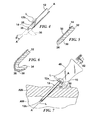
FIG. 1 is a side view, partially shown in section, of one embodiment of a visual veress needle assembly, including a veress needle and stylet, inserted through tissue; -
FIG. 1A is a cross-section of the veress needle and stylet ofFIG. 1 ; -
FIG. 2 is a top view of the visual veress needle assembly ofFIG. 1 ; -
FIG. 3 is a side view of the visual veress needle assembly ofFIG. 1 ; -
FIG. 4 is a side view of an alternate tip configuration of a stylet for use with a veress needle; -
FIG. 5 is a side view, shown in section, an articulating mechanism of the stylet incorporating an articulation mechanism; -
FIG. 6 is a side view, shown in section, of the stylet ofFIG. 5 in the articulated position;
and -
FIG. 7 is a side view, partially shown in section, of the veress needle assembly ofFIG. 1 with a valve assembly and inserted through tissue. - Embodiments of the presently disclosed visual veress needle assembly will now be described in detail with reference to the drawings wherein like numerals designate identical or corresponding elements in each of the several views. As is common in the art, the term 'proximal" refers to that part or component closer to the user or operator, i.e. surgeon or physician, while the term "distal" refers to that part or component further away from the user.
- Referring to
FIG. 1 , there is disclosed a visualveress needle assembly 10 for use in creating an incision I through a tissue, such as, for example abdominal wall AW. Visualveress needle assembly 10 allows a surgeon to viewvisual veress needle 12 as it passes through abdominal wall AW as well as viewing an operative site, for example, abdominal cavity AC within the body of a patient. Visualveress needle assembly 10 generally includes an optically conductingveress needle 12 and an optical insert or stylet 14 insertable throughneedle 12. Aconnector 16 is provided at aproximal end 18 ofstylet 14 to connectstylet 14 to various viewing, optical or electrical conversion or recording equipment, such as cameras, viewing screens, computerized data analysis devices, recording equipment, etc. The optically conductingveress needle 12 is made from glass, ceramic, polycarbonate or other suitable substantially clear or translucent resin/plastic, oxide or similar suitable material. As illustrated inFIG. 1 , alight source 50 is provided internally within theconnector 16 as at least part of the viewing, optical or electrical conversion or recording equipment included within theconnector 16. A distal end ortip 20 ofstylet 14 is formed of a viewing device described in more detail hereinbelow. - Referring now to
FIGS. 1-3 ,veress needle 12 generally includes ahollow body portion 22 having an openproximal end 24 for receipt ofstylet 14. As illustrated inFIG. 1A , at theproximal end 24, a concentrically circulartranslucent surface 12a is formed in theveress needle 12. An opendistal end 26 ofbody portion 22 is formed with a sharptissue penetrating tip 28.Tip 28 is formed at an angle α relative tobody portion 22 to facilitate slicing through abdominal wall AW (FIG. 3 ). In the exemplary embodiment of the visualveress needle assembly 10 illustrated inFIGS. 1, 1A and 2-7 , since thetip 28 is formed at angle α relative to thebody portion 22, an ovaltranslucent surface 12b is formed in theveress needle 12 at thedistal end 26. To enhance the transmission of light L emitted from thelight source 50, thelight source 50 may be configured in a circular or tubular configuration similar to a circular fluorescent bulb and disposed so as to maximize the intensity of light L emitted from thelight source 50 onto thesurface 12a of theveress needle 12. Light L emitted from thelight source 50 passes through thesurface 12a and travels through thebody portion 22 of theveress needle 12 and is then emitted from theoval surface 12b at thedistal end 26 to illuminate the incision I and underlying anatomical structures within the abdominal cavity AC. - Thus, the optically
conductive veress needle 12 includesproximal end 24 anddistal end 26. Theproximal end 24 and thedistal end 26 each have atranslucent surface body portion 22 of theveress needle 12 from theproximal end 24 to thedistal end 26. Thelight source 50 may be disposed in the vicinity of theproximal end 24 of theveress needle 12. Thelight source 50 may be configured and disposed to emit light L onto thetranslucent surface 12a at theproximal end 24 such that the light L pa sses through thebody portion 22 of theveress needle 12 and is emitted at thetranslucent surface 12b at thedistal end 26. - As noted above,
stylet 14 is provided to allow a surgeon to viewveress needle 12 as it forms incision I through abdominal wall AW, as well as viewing abdominal cavity AC including underlying anatomical structures (not shown) to prevent damaging those structures during insertion ofvisual veress needle 10. Adistal portion 30 ofstylet 14 may be flexible or articulating to view incision I, surrounding tissues or the insertion of additional devices through abdominal wall AW as described in more detail hereinbelow (FIG. 1 ). - In one embodiment,
stylet 14 includes abody portion 32 containing or substantially constructed from image and light carrying fiber optical materials.Proximal end 18 ofstylet 14 is connected toconnector 16 so as to pass the data transmitted throughbody portion 32 to devices enabling the surgeon to view the operative site. It should be noted that, while in the present embodiment,body portion 32 is formed from optical fibers, other means of obtaining and transmitting optical data are also contemplated. For example, while not specifically shown, an optical system including optical chip technology may be provided. -
Tip 20 includes alens 34 for obtaining an optical image. In this embodiment,lens 34 is a wide angle or fish eye type lens for maximizing the area viewed. The use ofwide angle lens 34 also assists in being able to view proximally back toward incision I. - Referring for the moment to
FIG. 4 , there is disclosed an alternative lens configuration provided ondistal tip 20 ofstylet 14.Tip 20 is formed with a generallyflat lens 36.Lens 36 is provided to view in a relatively narrow, generally singular direction to isolate, and maximize the image of, particular areas of the operative site.Lens 36 is formed at an angle P relative tobody portion 32 ofstylet 14 and relative to longitudinal centerline A-A of theveress needle 12. By articulating and/or rotatingdistal portion 30 ofstylet 14,lens 36 may be directed at the specific area to be viewed. - Referring now to
FIGS. 5 and 6 , as noted hereinabove,distal portion 30 of stylet is flexible so as to orientlens 34, orlens 36, in a particular desired direction. Various mechanisms are contemplated to accomplish the articulation, such as for, example, cables, springs, linkages, pneumatics, hydraulics, etc. In this embodiment, motion is provided by the incorporation of a length ofshape memory material 38 extending at least partially throughbody portion 32 anddistal portion 30 ofstylet 14.Shape memory material 38 is formed into a hook or J-shape in the unstressed condition. - With reference to
FIGS. 1 and5 , whendistal portion 30 ofstylet 14 is retracted withinhollow body portion 22 ofveress needle 12,shape memory material 38, and thusdistal portion 30 are constrained to a relatively straight configuration. As shown inFIGS. 1 and6 , asdistal portion 30 of stylet is advanced beyondtissue penetrating tip 28 ofveress needle 12,shape memory material 38 is no longer constrained and returns to the unstressed, generally J-shape configuration. Sinceshape memory material 38 is embedded withindistal portion 30, return ofshape memory material 38 to the unstressed configuration moves flexible distal portion with it. Thus, depending on the degree of advancement ofdistal portion 30 beyondtip 28 ofveress needle 14, the angle or orientation oflens 34 ondistal portion 30 relative toveress needle 14 is controlled. While not specifically shown, rotation ofstylet 14 withinveress needle 12 also serves to directlens 34. Therefore, the combination of articulation and rotational capabilities allows a surgeon to view the entire area within abdominal cavity AC. - In a specific embodiment, advancement of distal portion 30 a predetermined amount relative to
veress needle 12 results inlens 34 being oriented from approximately or substantially zero degrees (0°) to approximately or substantially one hundred eighty degrees (180°) relative to centerline axis A-A of the veress needle 12 (seeFIGS. 1-4 and7 ) to view incision I or other areas of abdominal wall AW to view the insertion of additional instrumentation through abdominal wall AW. - Finally, with reference to
FIG. 7 , oncestylet 14 has been used to observe the passage ofvisual veress needle 10 through abdominal wall AW, it may, as noted above, be oriented and utilized to view areas within abdominal cavity AC. Once visualization is complete,stylet 14 may be removed from withinhollow body portion 22 ofveress needle 12.Veress needle 12 may be left in place through incision I and used as a conduit for passage of insufflation gasses or other operative surgical instrumentation. For example, acannula body 40 having avalve 42 may be attached toproximal end 24 ofbody portion 22 to provide insufflation gasses into abdominal cavity AC. Alternatively,veress needle 12 may act as a guide for a cannula system having an inflation tube where the inflation tube is incapable of penetrating tissue. In this instance,veress needle 12 may be left in place or subsequently removed. - Thus, visual
veress needle assembly 10 provides a means of penetrating tissue and visualizing the penetration asvisual veress needle 12 passes through tissue. Additionally, underlying anatomical structures may be identified and observed during penetration to avoid or reduce the risk of injury to such structures. Further, the penetrations of additional tissue penetrating trocars may be observed, as well as locating additional penetration sites. - It will be understood that various modifications may be made to the embodiments disclosed herein. For example, as noted above, other optical system are contemplated for incorporation into the stylet, for example, optical chip technology, fluid visualization systems, etc. Further, the disclosed visual veress needle may incorporate other detection system including infrared or thermal or radiation detection capabilities. Additionally, other lens shapes are also contemplated, such as, for example telephoto or zoom lens, macro lenses, etc. Therefore, the above description should not be construed as limiting, but merely as exemplifications of particular embodiments. Those skilled in the art will envision other modifications within the scope and spirit of the claims appended hereto.
Claims (14)
- A visual veress needle assembly for viewing penetration of tissue and underlying anatomical structures comprising:an optically conducting veress needle having a body portion with a hollow interior and a tissue penetrating distal tip; anda stylet, the stylet being positionable through the hollow interior of the body portion of the needle, the sytlet having a body portion including image transmitting structure incorporated therein.wherein a distal portion of the stylet is flexible.
- The visual veress needle assembly as recited in claim 1, wherein the image transmitting structure of the body portion of the stylet is formed of optical fibers.
- The visual veress needle assembly as recited in claim 1 or claim 2, further comprising a lens at a distal tip portion of the stylet.
- The visual veress needle assembly as recited in claim 3, wherein the lens is a wide angle lens.
- The visual veress needle assembly as recited in claim 3, wherein the lens is a directional lens.
- The visual veress needle assembly as recited in any of the preceding claims, wherein the distal portion of the stylet is capable of articulating substantially 180° relative to a centerline axis of the hollow interior of the veress needle.
- The visual veress needle assembly as recited in any of the preceding claims, wherein the distal portion of the stylet incorporates a shape memory material.
- The visual veress needle assembly as recited in claim 7, wherein the shape memory material has a generally J-shape in an unstressed condition.
- The visual veress needle assembly as recited in any preceding claim, wherein the tissue penetrating tip of the veress needle is formed at a predetermined angle relative to the hollow body portion.
- The visual veress needle assembly as recited in any preceding claim, further comprising a connector disposed at a proximal end of the stylet, wherein the connector conveys optical data passing through the stylet to external imaging devices.
- The visual veress needle assembly as recited in any preceding claim, wherein the optically conductive veress needle includes a proximal end and a distal end, the proximal end and the distal end each having a translucent surface enabling transmission of light through the body portion of the veress needle from the proximal end to the distal end.
- The visual veress needle assembly as recited in claim 12, further comprising a light source disposed in the vicinity of the proximal end of the veress needle, the light source configured and disposed to emit light onto the translucent surface at the proximal end such that the light passes through the body portion of the veress needle and is emitted at the translucent surface at the distal end.
- The visual veress needle assembly as recited in any preceding claim, wherein the veress needle is made from a translucent material.
- The visual veress needle assembly as recited in claim 13, wherein the translucent material is one of the group consisting of a resin, a plastic and an oxide, preferably wherein the plastic is polycarbonate and the oxide is one of the group consisting of glass and ceramic.
Applications Claiming Priority (2)
| Application Number | Priority Date | Filing Date | Title |
|---|---|---|---|
| US17161009P | 2009-04-22 | 2009-04-22 | |
| US12/728,338 US20100274081A1 (en) | 2009-04-22 | 2010-03-22 | Visual veress needle assembly |
Publications (3)
| Publication Number | Publication Date |
|---|---|
| EP2243435A2 true EP2243435A2 (en) | 2010-10-27 |
| EP2243435A3 EP2243435A3 (en) | 2012-11-14 |
| EP2243435B1 EP2243435B1 (en) | 2015-04-01 |
Family
ID=42308015
Family Applications (1)
| Application Number | Title | Priority Date | Filing Date |
|---|---|---|---|
| EP10250806.6A Not-in-force EP2243435B1 (en) | 2009-04-22 | 2010-04-21 | Visual veress needle assembly |
Country Status (5)
| Country | Link |
|---|---|
| US (1) | US20100274081A1 (en) |
| EP (1) | EP2243435B1 (en) |
| JP (1) | JP2010253270A (en) |
| AU (1) | AU2010201287B2 (en) |
| CA (1) | CA2698033A1 (en) |
Families Citing this family (28)
| Publication number | Priority date | Publication date | Assignee | Title |
|---|---|---|---|---|
| US9186175B2 (en) | 2004-10-28 | 2015-11-17 | Nico Corporation | Surgical access assembly and method of using same |
| US9161820B2 (en) * | 2004-10-28 | 2015-10-20 | Nico Corporation | Surgical access assembly and method of using same |
| US20100121139A1 (en) | 2008-11-12 | 2010-05-13 | Ouyang Xiaolong | Minimally Invasive Imaging Systems |
| US20130310752A1 (en) * | 2011-02-18 | 2013-11-21 | Terumo Kabushiki Kaisha | Veress needle |
| CN103561633B (en) * | 2011-03-24 | 2016-02-24 | 意昂外科手术有限公司 | Laparoscope system |
| EP2744395B1 (en) * | 2011-09-08 | 2019-07-17 | Koninklijke Philips N.V. | Needle device with optical fibers integrated in a movable insert |
| WO2013173617A1 (en) | 2012-05-16 | 2013-11-21 | The Seaberg Company, Inc. | Safety needle |
| JP6266024B2 (en) | 2013-02-25 | 2018-01-24 | イーオン サージカル リミテッド | Surgical tool introducer |
| US11547446B2 (en) * | 2014-01-13 | 2023-01-10 | Trice Medical, Inc. | Fully integrated, disposable tissue visualization device |
| US9370295B2 (en) * | 2014-01-13 | 2016-06-21 | Trice Medical, Inc. | Fully integrated, disposable tissue visualization device |
| US10342579B2 (en) * | 2014-01-13 | 2019-07-09 | Trice Medical, Inc. | Fully integrated, disposable tissue visualization device |
| US10004533B2 (en) | 2014-09-30 | 2018-06-26 | Fateh Entabi | Surgical tools and system for safely accessing body cavities and methods of using the same |
| US10463399B2 (en) * | 2014-11-06 | 2019-11-05 | Asimion Inc. | Visually assisted entry of a Veress needle with a tapered videoscope for microlaparoscopy |
| WO2016157416A1 (en) * | 2015-03-31 | 2016-10-06 | 公立大学法人大阪市立大学 | Endoscope, attachment for endoscope, and endoscope system |
| US10105040B2 (en) * | 2015-05-08 | 2018-10-23 | Nanosurgery Technology Corporation | Imaging needle apparatus |
| EP3334322A1 (en) * | 2015-08-11 | 2018-06-20 | Trice Medical, Inc. | Fully integrated, disposable tissue visualization device |
| US10463492B2 (en) | 2015-11-17 | 2019-11-05 | Edwards Lifesciences Corporation | Systems and devices for setting an anchor |
| WO2017147605A1 (en) * | 2016-02-26 | 2017-08-31 | Samark Technology Llc | Video needle syringe |
| KR101845779B1 (en) * | 2017-05-31 | 2018-04-06 | (주)세원메디텍 | Medical fluid injection device for neuroplasty |
| EP3661412A4 (en) | 2017-08-04 | 2021-03-31 | Brigham and Women's Hospital, Inc. | Veress-type needles with illuminated guidance and safety features |
| US11382662B2 (en) | 2017-08-04 | 2022-07-12 | The Brigham And Women's Hospital, Inc. | Trocars and veress-type needles with illuminated guidance and safety features |
| KR102025221B1 (en) * | 2017-11-01 | 2019-09-25 | 해성옵틱스(주) | Endoscope for arthroscopy |
| KR102025220B1 (en) * | 2017-11-01 | 2019-09-25 | 해성옵틱스(주) | Endoscope for arthroscopy |
| KR102025219B1 (en) * | 2017-11-01 | 2019-09-25 | 해성옵틱스(주) | Endoscope for arthroscopy |
| US11135062B2 (en) | 2017-11-20 | 2021-10-05 | Valtech Cardio Ltd. | Cinching of dilated heart muscle |
| EP3773235B1 (en) | 2018-03-29 | 2023-07-19 | Trice Medical, Inc. | Fully integrated endoscope with biopsy capabilities |
| WO2020033862A1 (en) * | 2018-08-09 | 2020-02-13 | Optical Spine | Translucent illuminated endoscopic probe |
| WO2022107901A1 (en) * | 2020-11-17 | 2022-05-27 | 해성옵틱스(주) | Arthroscope |
Family Cites Families (28)
| Publication number | Priority date | Publication date | Assignee | Title |
|---|---|---|---|---|
| US288622A (en) * | 1883-11-20 | Chaelbs f | ||
| US5372138A (en) * | 1988-03-21 | 1994-12-13 | Boston Scientific Corporation | Acousting imaging catheters and the like |
| US5360405A (en) * | 1991-11-27 | 1994-11-01 | Inbae Yoon | Automatic retractable safety penetrating instrument |
| US5469853A (en) * | 1992-12-11 | 1995-11-28 | Tetrad Corporation | Bendable ultrasonic probe and sheath for use therewith |
| US5387197A (en) * | 1993-02-25 | 1995-02-07 | Ethicon, Inc. | Trocar safety shield locking mechanism |
| US5711755A (en) * | 1995-04-14 | 1998-01-27 | Vipera Systems, Inc. | Endoscopic diagnostic systems and associated methods employing infrared radiation |
| AU5727096A (en) * | 1995-05-04 | 1996-11-21 | Eric R. Cosman | Cool-tip electrode thermosurgery system |
| DE19547246C1 (en) * | 1995-12-18 | 1997-03-20 | Riek Siegfried | Medicinal needle containing spring-loaded guard |
| US7815436B2 (en) * | 1996-09-04 | 2010-10-19 | Immersion Corporation | Surgical simulation interface device and method |
| US5993463A (en) * | 1997-05-15 | 1999-11-30 | Regents Of The University Of Minnesota | Remote actuation of trajectory guide |
| US6183444B1 (en) * | 1998-05-16 | 2001-02-06 | Microheart, Inc. | Drug delivery module |
| JP3739592B2 (en) * | 1998-12-02 | 2006-01-25 | 株式会社モリタ製作所 | Laparoscopic device |
| US7366562B2 (en) * | 2003-10-17 | 2008-04-29 | Medtronic Navigation, Inc. | Method and apparatus for surgical navigation |
| US6468203B2 (en) * | 2000-04-03 | 2002-10-22 | Neoguide Systems, Inc. | Steerable endoscope and improved method of insertion |
| US10595710B2 (en) * | 2001-10-19 | 2020-03-24 | Visionscope Technologies Llc | Portable imaging system employing a miniature endoscope |
| US7070586B2 (en) * | 2003-01-17 | 2006-07-04 | Applied Medical Resources Corporation | Surgical access apparatus and method |
| US20070010702A1 (en) * | 2003-04-08 | 2007-01-11 | Xingwu Wang | Medical device with low magnetic susceptibility |
| US20050107870A1 (en) * | 2003-04-08 | 2005-05-19 | Xingwu Wang | Medical device with multiple coating layers |
| EP2545871B1 (en) * | 2004-06-29 | 2015-02-11 | Applied Medical Resources Corporation | Insufflating optical surgical instrument |
| JP4244941B2 (en) * | 2005-02-25 | 2009-03-25 | セイコーエプソン株式会社 | LIGHT EMITTING ELEMENT, LIGHT EMITTING DEVICE, AND ELECTRONIC DEVICE |
| US7963941B2 (en) * | 2005-04-12 | 2011-06-21 | Wilk Peter J | Intra-abdominal medical method and associated device |
| US7815564B2 (en) * | 2006-02-21 | 2010-10-19 | Boston Scientific Scimed, Inc. | Positioning system for manipulating a channel within a medical device |
| US7753843B2 (en) * | 2006-05-09 | 2010-07-13 | Boston Scientific Scimed, Inc. | Medical device positioning system |
| AU2007338691B2 (en) * | 2006-12-20 | 2013-07-04 | Covidien Lp | Surgical visual obturator |
| US8814874B2 (en) * | 2007-02-13 | 2014-08-26 | Medtronic Navigation, Inc. | Navigated cut guide for total knee reconstruction |
| US8002698B2 (en) * | 2007-04-04 | 2011-08-23 | Olympus Medical Systems Corp. | Therapeutic method that uses overtube |
| EP2134238B1 (en) * | 2007-04-17 | 2016-08-03 | SurgiQuest, Incorporated | Endoluminal and transluminal surgical devices |
| CA2700523A1 (en) * | 2007-09-24 | 2009-04-02 | Surgivision, Inc. | Mri-guided medical interventional systems and methods |
-
2010
- 2010-03-22 US US12/728,338 patent/US20100274081A1/en not_active Abandoned
- 2010-03-29 CA CA2698033A patent/CA2698033A1/en not_active Abandoned
- 2010-03-31 AU AU2010201287A patent/AU2010201287B2/en not_active Ceased
- 2010-04-15 JP JP2010094519A patent/JP2010253270A/en active Pending
- 2010-04-21 EP EP10250806.6A patent/EP2243435B1/en not_active Not-in-force
Non-Patent Citations (1)
| Title |
|---|
| None |
Also Published As
| Publication number | Publication date |
|---|---|
| EP2243435A3 (en) | 2012-11-14 |
| AU2010201287A1 (en) | 2010-11-11 |
| AU2010201287B2 (en) | 2015-02-19 |
| CA2698033A1 (en) | 2010-10-22 |
| JP2010253270A (en) | 2010-11-11 |
| EP2243435B1 (en) | 2015-04-01 |
| US20100274081A1 (en) | 2010-10-28 |
Similar Documents
| Publication | Publication Date | Title |
|---|---|---|
| EP2243435B1 (en) | Visual veress needle assembly | |
| AU2007338691B2 (en) | Surgical visual obturator | |
| EP2104461B1 (en) | Access sheath with removable optical penetrating member | |
| US8070767B2 (en) | Optical penetrating adapter for surgical portal | |
| ES2901382T3 (en) | Optical coupler for an endoscope | |
| US20030153926A1 (en) | Distracting cannula for sheathless arthroscope | |
| US10166039B2 (en) | Viewing trocar | |
| JP2006280918A (en) | Optical closure | |
| EP2449953B1 (en) | Mirrored arthroscope | |
| JP2011125709A (en) | Visible obturator with tip openings | |
| JP5461660B2 (en) | Obturator assembly | |
| US9814369B2 (en) | Pivoting three-dimensional video endoscope | |
| EP2241276A1 (en) | Bendable veress needle assembly | |
| US9999443B2 (en) | Instrument head single loader | |
| US11602266B2 (en) | Flexible articulating surgical probe | |
| EP2221005B1 (en) | Endoscopic retractor |
Legal Events
| Date | Code | Title | Description |
|---|---|---|---|
| PUAI | Public reference made under article 153(3) epc to a published international application that has entered the european phase |
Free format text: ORIGINAL CODE: 0009012 |
|
| AK | Designated contracting states |
Kind code of ref document: A2 Designated state(s): AT BE BG CH CY CZ DE DK EE ES FI FR GB GR HR HU IE IS IT LI LT LU LV MC MK MT NL NO PL PT RO SE SI SK SM TR |
|
| AX | Request for extension of the european patent |
Extension state: AL BA ME RS |
|
| PUAL | Search report despatched |
Free format text: ORIGINAL CODE: 0009013 |
|
| AK | Designated contracting states |
Kind code of ref document: A3 Designated state(s): AT BE BG CH CY CZ DE DK EE ES FI FR GB GR HR HU IE IS IT LI LT LU LV MC MK MT NL NO PL PT RO SE SI SK SM TR |
|
| AX | Request for extension of the european patent |
Extension state: AL BA ME RS |
|
| RIC1 | Information provided on ipc code assigned before grant |
Ipc: A61B 17/34 20060101AFI20121005BHEP Ipc: A61B 17/00 20060101ALN20121005BHEP Ipc: A61B 19/00 20060101ALN20121005BHEP |
|
| RAP1 | Party data changed (applicant data changed or rights of an application transferred) |
Owner name: COVIDIEN LP |
|
| 17P | Request for examination filed |
Effective date: 20130107 |
|
| 17Q | First examination report despatched |
Effective date: 20130701 |
|
| GRAP | Despatch of communication of intention to grant a patent |
Free format text: ORIGINAL CODE: EPIDOSNIGR1 |
|
| RIC1 | Information provided on ipc code assigned before grant |
Ipc: A61B 17/00 20060101ALN20141114BHEP Ipc: A61B 19/00 20060101ALN20141114BHEP Ipc: A61B 17/34 20060101AFI20141114BHEP |
|
| INTG | Intention to grant announced |
Effective date: 20141202 |
|
| GRAS | Grant fee paid |
Free format text: ORIGINAL CODE: EPIDOSNIGR3 |
|
| GRAA | (expected) grant |
Free format text: ORIGINAL CODE: 0009210 |
|
| AK | Designated contracting states |
Kind code of ref document: B1 Designated state(s): AT BE BG CH CY CZ DE DK EE ES FI FR GB GR HR HU IE IS IT LI LT LU LV MC MK MT NL NO PL PT RO SE SI SK SM TR |
|
| REG | Reference to a national code |
Ref country code: GB Ref legal event code: FG4D |
|
| REG | Reference to a national code |
Ref country code: CH Ref legal event code: EP |
|
| REG | Reference to a national code |
Ref country code: IE Ref legal event code: FG4D |
|
| REG | Reference to a national code |
Ref country code: DE Ref legal event code: R096 Ref document number: 602010023561 Country of ref document: DE Effective date: 20150513 |
|
| REG | Reference to a national code |
Ref country code: AT Ref legal event code: REF Ref document number: 718622 Country of ref document: AT Kind code of ref document: T Effective date: 20150515 |
|
| REG | Reference to a national code |
Ref country code: NL Ref legal event code: VDEP Effective date: 20150401 |
|
| REG | Reference to a national code |
Ref country code: AT Ref legal event code: MK05 Ref document number: 718622 Country of ref document: AT Kind code of ref document: T Effective date: 20150401 |
|
| REG | Reference to a national code |
Ref country code: LT Ref legal event code: MG4D |
|
| PG25 | Lapsed in a contracting state [announced via postgrant information from national office to epo] |
Ref country code: NL Free format text: LAPSE BECAUSE OF FAILURE TO SUBMIT A TRANSLATION OF THE DESCRIPTION OR TO PAY THE FEE WITHIN THE PRESCRIBED TIME-LIMIT Effective date: 20150401 |
|
| PG25 | Lapsed in a contracting state [announced via postgrant information from national office to epo] |
Ref country code: PT Free format text: LAPSE BECAUSE OF FAILURE TO SUBMIT A TRANSLATION OF THE DESCRIPTION OR TO PAY THE FEE WITHIN THE PRESCRIBED TIME-LIMIT Effective date: 20150803 Ref country code: FI Free format text: LAPSE BECAUSE OF FAILURE TO SUBMIT A TRANSLATION OF THE DESCRIPTION OR TO PAY THE FEE WITHIN THE PRESCRIBED TIME-LIMIT Effective date: 20150401 Ref country code: ES Free format text: LAPSE BECAUSE OF FAILURE TO SUBMIT A TRANSLATION OF THE DESCRIPTION OR TO PAY THE FEE WITHIN THE PRESCRIBED TIME-LIMIT Effective date: 20150401 Ref country code: LT Free format text: LAPSE BECAUSE OF FAILURE TO SUBMIT A TRANSLATION OF THE DESCRIPTION OR TO PAY THE FEE WITHIN THE PRESCRIBED TIME-LIMIT Effective date: 20150401 Ref country code: CZ Free format text: LAPSE BECAUSE OF FAILURE TO SUBMIT A TRANSLATION OF THE DESCRIPTION OR TO PAY THE FEE WITHIN THE PRESCRIBED TIME-LIMIT Effective date: 20150401 Ref country code: HR Free format text: LAPSE BECAUSE OF FAILURE TO SUBMIT A TRANSLATION OF THE DESCRIPTION OR TO PAY THE FEE WITHIN THE PRESCRIBED TIME-LIMIT Effective date: 20150401 Ref country code: NO Free format text: LAPSE BECAUSE OF FAILURE TO SUBMIT A TRANSLATION OF THE DESCRIPTION OR TO PAY THE FEE WITHIN THE PRESCRIBED TIME-LIMIT Effective date: 20150701 |
|
| PG25 | Lapsed in a contracting state [announced via postgrant information from national office to epo] |
Ref country code: LV Free format text: LAPSE BECAUSE OF FAILURE TO SUBMIT A TRANSLATION OF THE DESCRIPTION OR TO PAY THE FEE WITHIN THE PRESCRIBED TIME-LIMIT Effective date: 20150401 Ref country code: GR Free format text: LAPSE BECAUSE OF FAILURE TO SUBMIT A TRANSLATION OF THE DESCRIPTION OR TO PAY THE FEE WITHIN THE PRESCRIBED TIME-LIMIT Effective date: 20150702 Ref country code: AT Free format text: LAPSE BECAUSE OF FAILURE TO SUBMIT A TRANSLATION OF THE DESCRIPTION OR TO PAY THE FEE WITHIN THE PRESCRIBED TIME-LIMIT Effective date: 20150401 Ref country code: IS Free format text: LAPSE BECAUSE OF FAILURE TO SUBMIT A TRANSLATION OF THE DESCRIPTION OR TO PAY THE FEE WITHIN THE PRESCRIBED TIME-LIMIT Effective date: 20150801 |
|
| REG | Reference to a national code |
Ref country code: CH Ref legal event code: PL |
|
| REG | Reference to a national code |
Ref country code: DE Ref legal event code: R097 Ref document number: 602010023561 Country of ref document: DE |
|
| PG25 | Lapsed in a contracting state [announced via postgrant information from national office to epo] |
Ref country code: MC Free format text: LAPSE BECAUSE OF FAILURE TO SUBMIT A TRANSLATION OF THE DESCRIPTION OR TO PAY THE FEE WITHIN THE PRESCRIBED TIME-LIMIT Effective date: 20150401 Ref country code: LI Free format text: LAPSE BECAUSE OF NON-PAYMENT OF DUE FEES Effective date: 20150430 Ref country code: CH Free format text: LAPSE BECAUSE OF NON-PAYMENT OF DUE FEES Effective date: 20150430 Ref country code: EE Free format text: LAPSE BECAUSE OF FAILURE TO SUBMIT A TRANSLATION OF THE DESCRIPTION OR TO PAY THE FEE WITHIN THE PRESCRIBED TIME-LIMIT Effective date: 20150401 Ref country code: DK Free format text: LAPSE BECAUSE OF FAILURE TO SUBMIT A TRANSLATION OF THE DESCRIPTION OR TO PAY THE FEE WITHIN THE PRESCRIBED TIME-LIMIT Effective date: 20150401 Ref country code: IT Free format text: LAPSE BECAUSE OF FAILURE TO SUBMIT A TRANSLATION OF THE DESCRIPTION OR TO PAY THE FEE WITHIN THE PRESCRIBED TIME-LIMIT Effective date: 20150401 |
|
| PLBE | No opposition filed within time limit |
Free format text: ORIGINAL CODE: 0009261 |
|
| STAA | Information on the status of an ep patent application or granted ep patent |
Free format text: STATUS: NO OPPOSITION FILED WITHIN TIME LIMIT |
|
| PG25 | Lapsed in a contracting state [announced via postgrant information from national office to epo] |
Ref country code: PL Free format text: LAPSE BECAUSE OF FAILURE TO SUBMIT A TRANSLATION OF THE DESCRIPTION OR TO PAY THE FEE WITHIN THE PRESCRIBED TIME-LIMIT Effective date: 20150401 Ref country code: RO Free format text: LAPSE BECAUSE OF NON-PAYMENT OF DUE FEES Effective date: 20150401 Ref country code: SK Free format text: LAPSE BECAUSE OF FAILURE TO SUBMIT A TRANSLATION OF THE DESCRIPTION OR TO PAY THE FEE WITHIN THE PRESCRIBED TIME-LIMIT Effective date: 20150401 |
|
| 26N | No opposition filed |
Effective date: 20160105 |
|
| REG | Reference to a national code |
Ref country code: FR Ref legal event code: PLFP Year of fee payment: 7 |
|
| PG25 | Lapsed in a contracting state [announced via postgrant information from national office to epo] |
Ref country code: SI Free format text: LAPSE BECAUSE OF FAILURE TO SUBMIT A TRANSLATION OF THE DESCRIPTION OR TO PAY THE FEE WITHIN THE PRESCRIBED TIME-LIMIT Effective date: 20150401 |
|
| PG25 | Lapsed in a contracting state [announced via postgrant information from national office to epo] |
Ref country code: BE Free format text: LAPSE BECAUSE OF FAILURE TO SUBMIT A TRANSLATION OF THE DESCRIPTION OR TO PAY THE FEE WITHIN THE PRESCRIBED TIME-LIMIT Effective date: 20150401 |
|
| PG25 | Lapsed in a contracting state [announced via postgrant information from national office to epo] |
Ref country code: MT Free format text: LAPSE BECAUSE OF FAILURE TO SUBMIT A TRANSLATION OF THE DESCRIPTION OR TO PAY THE FEE WITHIN THE PRESCRIBED TIME-LIMIT Effective date: 20150401 |
|
| REG | Reference to a national code |
Ref country code: FR Ref legal event code: PLFP Year of fee payment: 8 |
|
| PGFP | Annual fee paid to national office [announced via postgrant information from national office to epo] |
Ref country code: FR Payment date: 20170322 Year of fee payment: 8 |
|
| PG25 | Lapsed in a contracting state [announced via postgrant information from national office to epo] |
Ref country code: HU Free format text: LAPSE BECAUSE OF FAILURE TO SUBMIT A TRANSLATION OF THE DESCRIPTION OR TO PAY THE FEE WITHIN THE PRESCRIBED TIME-LIMIT; INVALID AB INITIO Effective date: 20100421 Ref country code: SM Free format text: LAPSE BECAUSE OF FAILURE TO SUBMIT A TRANSLATION OF THE DESCRIPTION OR TO PAY THE FEE WITHIN THE PRESCRIBED TIME-LIMIT Effective date: 20150401 Ref country code: BG Free format text: LAPSE BECAUSE OF FAILURE TO SUBMIT A TRANSLATION OF THE DESCRIPTION OR TO PAY THE FEE WITHIN THE PRESCRIBED TIME-LIMIT Effective date: 20150401 |
|
| PGFP | Annual fee paid to national office [announced via postgrant information from national office to epo] |
Ref country code: GB Payment date: 20170324 Year of fee payment: 8 Ref country code: IE Payment date: 20170323 Year of fee payment: 8 |
|
| PG25 | Lapsed in a contracting state [announced via postgrant information from national office to epo] |
Ref country code: CY Free format text: LAPSE BECAUSE OF FAILURE TO SUBMIT A TRANSLATION OF THE DESCRIPTION OR TO PAY THE FEE WITHIN THE PRESCRIBED TIME-LIMIT Effective date: 20150401 Ref country code: SE Free format text: LAPSE BECAUSE OF FAILURE TO SUBMIT A TRANSLATION OF THE DESCRIPTION OR TO PAY THE FEE WITHIN THE PRESCRIBED TIME-LIMIT Effective date: 20150401 |
|
| PGFP | Annual fee paid to national office [announced via postgrant information from national office to epo] |
Ref country code: DE Payment date: 20170321 Year of fee payment: 8 |
|
| PG25 | Lapsed in a contracting state [announced via postgrant information from national office to epo] |
Ref country code: TR Free format text: LAPSE BECAUSE OF FAILURE TO SUBMIT A TRANSLATION OF THE DESCRIPTION OR TO PAY THE FEE WITHIN THE PRESCRIBED TIME-LIMIT Effective date: 20150401 |
|
| PG25 | Lapsed in a contracting state [announced via postgrant information from national office to epo] |
Ref country code: LU Free format text: LAPSE BECAUSE OF NON-PAYMENT OF DUE FEES Effective date: 20150421 |
|
| PG25 | Lapsed in a contracting state [announced via postgrant information from national office to epo] |
Ref country code: MK Free format text: LAPSE BECAUSE OF FAILURE TO SUBMIT A TRANSLATION OF THE DESCRIPTION OR TO PAY THE FEE WITHIN THE PRESCRIBED TIME-LIMIT Effective date: 20150401 |
|
| REG | Reference to a national code |
Ref country code: DE Ref legal event code: R119 Ref document number: 602010023561 Country of ref document: DE |
|
| GBPC | Gb: european patent ceased through non-payment of renewal fee |
Effective date: 20180421 |
|
| REG | Reference to a national code |
Ref country code: IE Ref legal event code: MM4A |
|
| PG25 | Lapsed in a contracting state [announced via postgrant information from national office to epo] |
Ref country code: DE Free format text: LAPSE BECAUSE OF NON-PAYMENT OF DUE FEES Effective date: 20181101 |
|
| PG25 | Lapsed in a contracting state [announced via postgrant information from national office to epo] |
Ref country code: GB Free format text: LAPSE BECAUSE OF NON-PAYMENT OF DUE FEES Effective date: 20180421 |
|
| PG25 | Lapsed in a contracting state [announced via postgrant information from national office to epo] |
Ref country code: FR Free format text: LAPSE BECAUSE OF NON-PAYMENT OF DUE FEES Effective date: 20180430 Ref country code: IE Free format text: LAPSE BECAUSE OF NON-PAYMENT OF DUE FEES Effective date: 20180421 |