EP2243149B1 - Multiple grooved vacuum coupling - Google Patents
Multiple grooved vacuum coupling Download PDFInfo
- Publication number
- EP2243149B1 EP2243149B1 EP09711254A EP09711254A EP2243149B1 EP 2243149 B1 EP2243149 B1 EP 2243149B1 EP 09711254 A EP09711254 A EP 09711254A EP 09711254 A EP09711254 A EP 09711254A EP 2243149 B1 EP2243149 B1 EP 2243149B1
- Authority
- EP
- European Patent Office
- Prior art keywords
- coupling system
- spindle
- circumferential surface
- ring
- cylindrical target
- Prior art date
- Legal status (The legal status is an assumption and is not a legal conclusion. Google has not performed a legal analysis and makes no representation as to the accuracy of the status listed.)
- Active
Links
Images

Classifications
-
- H—ELECTRICITY
- H01—ELECTRIC ELEMENTS
- H01J—ELECTRIC DISCHARGE TUBES OR DISCHARGE LAMPS
- H01J37/00—Discharge tubes with provision for introducing objects or material to be exposed to the discharge, e.g. for the purpose of examination or processing thereof
- H01J37/32—Gas-filled discharge tubes
- H01J37/34—Gas-filled discharge tubes operating with cathodic sputtering
- H01J37/3411—Constructional aspects of the reactor
- H01J37/3414—Targets
- H01J37/3423—Shape
-
- C—CHEMISTRY; METALLURGY
- C23—COATING METALLIC MATERIAL; COATING MATERIAL WITH METALLIC MATERIAL; CHEMICAL SURFACE TREATMENT; DIFFUSION TREATMENT OF METALLIC MATERIAL; COATING BY VACUUM EVAPORATION, BY SPUTTERING, BY ION IMPLANTATION OR BY CHEMICAL VAPOUR DEPOSITION, IN GENERAL; INHIBITING CORROSION OF METALLIC MATERIAL OR INCRUSTATION IN GENERAL
- C23C—COATING METALLIC MATERIAL; COATING MATERIAL WITH METALLIC MATERIAL; SURFACE TREATMENT OF METALLIC MATERIAL BY DIFFUSION INTO THE SURFACE, BY CHEMICAL CONVERSION OR SUBSTITUTION; COATING BY VACUUM EVAPORATION, BY SPUTTERING, BY ION IMPLANTATION OR BY CHEMICAL VAPOUR DEPOSITION, IN GENERAL
- C23C14/00—Coating by vacuum evaporation, by sputtering or by ion implantation of the coating forming material
- C23C14/22—Coating by vacuum evaporation, by sputtering or by ion implantation of the coating forming material characterised by the process of coating
- C23C14/34—Sputtering
- C23C14/3407—Cathode assembly for sputtering apparatus, e.g. Target
-
- F—MECHANICAL ENGINEERING; LIGHTING; HEATING; WEAPONS; BLASTING
- F16—ENGINEERING ELEMENTS AND UNITS; GENERAL MEASURES FOR PRODUCING AND MAINTAINING EFFECTIVE FUNCTIONING OF MACHINES OR INSTALLATIONS; THERMAL INSULATION IN GENERAL
- F16L—PIPES; JOINTS OR FITTINGS FOR PIPES; SUPPORTS FOR PIPES, CABLES OR PROTECTIVE TUBING; MEANS FOR THERMAL INSULATION IN GENERAL
- F16L21/00—Joints with sleeve or socket
- F16L21/06—Joints with sleeve or socket with a divided sleeve or ring clamping around the pipe ends
- F16L21/065—Joints with sleeve or socket with a divided sleeve or ring clamping around the pipe ends tightened by tangentially-arranged threaded pins
-
- H—ELECTRICITY
- H01—ELECTRIC ELEMENTS
- H01J—ELECTRIC DISCHARGE TUBES OR DISCHARGE LAMPS
- H01J37/00—Discharge tubes with provision for introducing objects or material to be exposed to the discharge, e.g. for the purpose of examination or processing thereof
- H01J37/32—Gas-filled discharge tubes
- H01J37/34—Gas-filled discharge tubes operating with cathodic sputtering
- H01J37/3411—Constructional aspects of the reactor
- H01J37/3435—Target holders (includes backing plates and endblocks)
-
- Y—GENERAL TAGGING OF NEW TECHNOLOGICAL DEVELOPMENTS; GENERAL TAGGING OF CROSS-SECTIONAL TECHNOLOGIES SPANNING OVER SEVERAL SECTIONS OF THE IPC; TECHNICAL SUBJECTS COVERED BY FORMER USPC CROSS-REFERENCE ART COLLECTIONS [XRACs] AND DIGESTS
- Y10—TECHNICAL SUBJECTS COVERED BY FORMER USPC
- Y10T—TECHNICAL SUBJECTS COVERED BY FORMER US CLASSIFICATION
- Y10T403/00—Joints and connections
- Y10T403/66—Interfitted members with external bridging piece
Definitions
- the present invention relates to a coupling system to releasably affix a cylindrical target to a spindle.
- Cylindrical magnetrons with rotating cylindrical targets are being used more and more over the last decade.
- a cylindrical target in operation must be supported, rotated, cooled and energized.
- the sputtering installation is energized through one end block at one end of the cylindrical target (cantilever mode) or two end blocks at the two ends of the cylindrical target.
- the one or two end blocks are equipped with a rotatable spindle to which the target is attached.
- the used target When a target is depleted, the used target must be detached form the spindle to have it replaced with a fresh one. Therefore the coupling between the spindle and the target must be releasable.
- US-A-5,591,314 discloses a coupling system to releasably affix a cylindrical target to a spindle by means of a threaded spindle collar engaging threads on the outside surface of the target.
- This system is known as the reference in the art and has been used on a wide scale for several years. Nevertheless this system has one drawback.
- the threaded spindle collar requires a screw movement to fix the target to the spindle. This screw movement makes it difficult to position a collar ring at exact right angles with respect to the spindle. The result is that the cylindrical target and the spindle risk to be not one hundred per cent aligned with each other, which is detrimental for both the life time and the sealing of the coupling.
- WO-A1-2004/085902 (Bekaert Advanced Coatings) discloses a universal coupling system for cylindrical targets.
- the embodiments disclosed in Figures 1 , 2 , 3 , 5 and 6 on the one hand, all have the same or a similar helical thread system necessitating also a screw movement with the disadvantages as mentioned supra.
- Figure 4 of WO-A1-2004/085902 discloses a coupling with a non-helical groove. Finite element analysis and experience, however, have shown that the stresses in the neighborhood of this helical groove are unacceptably high.
- WO-A2-2006/135528 discloses a system using a clamp and modifications to be made to threaded targets and endblock components so that they can be clamped.
- the modification includes forming a circular groove near the end of the target and inserting a retaining ring in the groove to hold a flange ring that encircles the end of the target.
- a clamp ring fits over the flange and an adapted spindle.
- Targets not having a threaded portion may also be affixed in this way.
- the stresses in the neighborhood of a single groove be it helical or cylindrical, will be unacceptably high.
- a coupling system to releasably affix a cylindrical target to a spindle.
- the coupling system comprises:
- the separate circular grooves are not helical and do not form a screw fixation. Hence, the problem of positioning at right angles has been avoided.
- the two or more separate grooves allow the stresses to be spread over the various grooves, which increases life time and avoids premature fracture.
- the tightening means may comprise a clamping ring adapted to engage at one side with the interface ring and at another side with the spindle.
- the clamping ring may be made out of two or more clamping ring segments and the interface ring may also be made of two or more interface ring segments.
- the joins of the interface ring segments are covered by clamping ring segments, i.e. the joins of the interface ring segments and the joins of the clamping ring segments are not located near each other.
- the circular grooves are made by two or more separate rings positioned on the end portion of the target and forming the outer circumferential surface. These separate rings can be shifted on the target and avoid a machining on the target itself.
- each clamping ring segments is forming a single metal piece with a corresponding interface ring segment.
- the two or more separate circular grooves are made by a machining operation in said cylindrical target.
- the circular grooves have different depths, the greater depth is preferably positioned at the side of said cylindrical target since the greater mechanical stresses are present there.
- the greater depths are positioned at the other side, e.g. in case of a cylindrical target with increasing thickness at the ends.
- the circular grooves preferably have a rounded, rectangular or conical shape.
- the coupling system may further comprise a retainer ring between the interface ring and the clamping ring.
- the retainer ring presses the two (or more) segments of the interface ring against one another to keep them engaged with the circular grooves at the end of the target tube for easy mounting of the target to the spindle.
- the retainer ring can be an elastic sealing ring which can hold the two (or more) segments of the interface ring together on the target end during mounting.
- the interface ring is different from the clamping ring.
- the interface ring and the clamping ring are the same piece.
- a coupling system to releasably affix a cylindrical target to a spindle.
- the coupling system comprises:
- the coupling system of the present invention has many advantages. Due to the repeated groove and tooth contacts between interface ring and the clamping ring (possibly in combination with a sealing ring), the seal between the target and the spindle (or endblock) is watertight so that cooling water does not flow through the outside of the target causing leaks. The seal further withstands high temperatures without failure if the target becomes too hot.
- the affixation is strong enough to support the target, to transmit a rotational force and to be electrically conductive. The affixation is such that attachment and detachment of the target from the spindle is fast and easy, without the need of specialized tools. Downtime for changing eroded targets is minimized in this way. More importantly, the coupling is such that mounting errors, by misalignment for example, are avoided.
- the coupling system furthermore is less expensive to produce than, for example, threaded couplings.
- a cylindrical target adapted to work with the coupling according to the first aspect of the invention.
- the cylindrical target comprises an end portion.
- the end portion has an outer circumferential surface and the outer circumferential surface has two or more separate circular grooves.
- an interface ring adapted to work with the coupling according to the first aspect of the invention.
- the interface ring has an inner circumferential surface. This inner circumferential surface is adapted to engage with two or more separate circular grooves in the outer circumference of the end portion of a cylindrical target.
- a backing tube that is suitable for use in a cylindrical target according the second aspect of the invention wherein said backing tube has an end portion, the outer circumferential surface of which has two or more separate circular grooves.
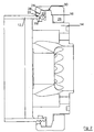
- Figure 1 shows a coupling system with multiple circular grooves in the cylindrical target.
- Figure 2 shows a cross-sectional view of the coupling system of Figure 1 .
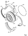
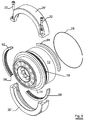
- Figures 3 shows an exploded view of the coupling system of Figure 1 .
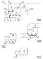
- Figure 4 shows a detailed cross-sectional view of the coupling system according to the invention.
- Figure 5 shows an interface ring having circular grooves with different depths.
- Figure 6 shows a circular grooves on a target made by separate rings.
- Figure 7 shows an interface ring having other shaped grooves.
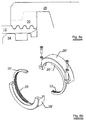
- Figure 8a shows a cross-sectional view of an alternative embodiment
- Figure 8b shows an exploded view of an alternative embodiment of a coupling system.
- Figure 9 shows an exploded view of yet another alternative embodiment.
- Figures 1 , 2 , 3 and 4 illustrate an embodiment of a coupling system 10 whereby a cylindrical target 12 is releasably coupled to a spindle 14.
- the spindle 14 has a flange portion 16.
- the cylindrical target 12 has two or more circular circumferential grooves 18 at the end. In one embodiment the cylindrical target 12 has four circular grooves 18. Each circular groove extends completely around the target. The grooves are positioned preferably at a regular interval parallel from each other.
- the cylindrical target can be made monolithic out of the material to be sputtered and provided with the two or more circular grooves at one or both of its ends.
- the cylindrical target can comprise a backing tube on which target material is deposited by electrolytic deposition, flame spraying, sputtering, clamping, welding or brazing or any such other means known in the art.
- the target material is deposited on the outer surface of the backing tube.
- the backing tube is provided with two or more circular grooves at one or both of its end portions.
- the coupling system further comprises an interface ring 20 which is composed of two or more interface ring segments 20',20". See Figure 3 .
- the interface ring 20 has an inner diameter which is greater or equal than the outer diameter of the cylindrical target 12.
- the circular grooves 22 of the interface ring 20 are adapted to engage with the circular grooves 18 of the cylindrical target 12.
- the interface ring 20 further has a flange extremity 24. In coupled status, this flange extremity 24 of the interface ring 20 abuts against the flange portion 16 of the spindle 14.
- the coupling system further comprises a clamping ring 26, which is composed of two or more clamp segments 26',26". Each clamp segment has an inwardly oriented clamp recess 30. In coupled status this clamp recess 30 encloses the flange portion 16 of the spindle 14 and the flange extremity 24 of the interface ring 20. Preferably the surfaces of the flange portion 16 and the flange extremity 24 are slightly conical. The clamp recess 30 also has a matching conical surface.
- the coupling system further comprises a 'C' shaped, retainer ring 28 fitting in a recess of the interface ring 20, for holding both interface ring segments on the end of the target during the mounting of the target.
- the retainer ring 28 may be an elastic sealing O-ring which provides an additional sealing function when compressed between the interface ring 20 and the clamping ring 26. ( Fig 3 ).
- Figure 3 shows a demounted view of the coupling system 10.
- the interface ring segments 20',20" are engaged with the circular grooves 18 at the end of the target 12 and held in position with the retainer ring 28.
- the cylindrical target 12 is slid onto the spindle 14, so that the end of the cylindrical target 12 abuts the lower part of the flange portion 16 of the spindle 14.
- the two clamping ring segments 26' and 26" are mounted onto the interface ring segments 20' and 20" and the flange portion 16 of the spindle 14.
- the two clamping ring segments 26' and 26" are joined together at places which do not correspond to the places where the two interface ring segments 20' and 20" join one another.
- the joining position of the two clamping ring segments 26' and 26" is shifted 90 degrees from the joining of the two interface ring segments 20' and 20".
- the clamp segments of the clamping ring 26 are held together by fastening means, such as a bolt or a screw 32 ( Fig 3 ).
- Figure 5 shows an embodiment of a coupling system comprising an interface ring 50 having grooves (52, 54, 56, 58) with different depths.
- the greater depth of groove 52 is at the side of the cylindrical target 12, and this for reasons of a greater tension at that side.
- only groove 52 is deeper, while the other grooves (54, 56, 58) have an equal depth.
- Figure 6 shows an alternative embodiment where the grooves on the end portion of the cylindrical target 12 are realized by means of two separate rings 62, 64.
- An interface ring 66 has an inner circumferential surface closely engaging with these separate rings 62, 64.
- This embodiment has the advantage that the circular grooves need not to be made by machining the end portion of the cylindrical target 12. Hence, there is no weakening of the end portion of the cylindrical target 12.
- Figure 7 shows an alternative embodiment of an interface ring 70 with circular grooves having a different shape (conical) in cross-section.
- a groove shape is a rectangular groove.
- Figure 8a and Figure 8b show alternative embodiments where the interface ring and the clamping ring are one piece. This facilitates mounting and demounting even more.
- the interface ring and the clamping ring are fixed together as to form one piece. This is illustrated by the cross-section in Figure 8a .
- an interface ring segment 20', 20" is fixed to a clamping ring segment 26', 26" so that it is shifted over some degrees and protrudes somewhat out of the clamping ring. In this way the joins of the interface ring segments are shifted towards the joins of the clamping ring segments, as such providing extra sealing.
- Figure 9 shows an exploded view of yet another embodiment of the coupling according to the invention.
- the difference with the embodiment of Figures 1 , 2 , 3 and 4 mainly lies in the interface ring.
- the interface ring has three segments 92, 94 and 96 instead of only two segments. All these segments cover about 120° (instead of 180° in Figures 1 , 2 , 3 and 4 ).
Landscapes
- Engineering & Computer Science (AREA)
- Chemical & Material Sciences (AREA)
- Mechanical Engineering (AREA)
- Plasma & Fusion (AREA)
- Analytical Chemistry (AREA)
- General Engineering & Computer Science (AREA)
- Physics & Mathematics (AREA)
- Metallurgy (AREA)
- Materials Engineering (AREA)
- Organic Chemistry (AREA)
- Chemical Kinetics & Catalysis (AREA)
- Physical Vapour Deposition (AREA)
- Mutual Connection Of Rods And Tubes (AREA)
- Flanged Joints, Insulating Joints, And Other Joints (AREA)
- Thermal Insulation (AREA)
- Cable Accessories (AREA)
- Clamps And Clips (AREA)
Abstract
Description
- The present invention relates to a coupling system to releasably affix a cylindrical target to a spindle.
- Cylindrical magnetrons with rotating cylindrical targets are being used more and more over the last decade. A cylindrical target in operation must be supported, rotated, cooled and energized. Normally the sputtering installation is energized through one end block at one end of the cylindrical target (cantilever mode) or two end blocks at the two ends of the cylindrical target. The one or two end blocks are equipped with a rotatable spindle to which the target is attached. When a target is depleted, the used target must be detached form the spindle to have it replaced with a fresh one. Therefore the coupling between the spindle and the target must be releasable.
- Supporting, rotating, energizing and cooling of the cylindrical targets is all done through the spindles. One side of the cylindrical target, the outer side holding target material operates under vacuum while the other side of the cylindrical target, the inner side, operates under a substantially higher pressure of a coolant - usually water - that is circulated through the target The problem of water leaks occurring at the interface between the spindle and the cylindrical target have resulted in the development of various vacuum coupling and sealing systems. In addition - certainty in the case of a cantilever mount - the moment exerted on the spindle and hence on the coupling is considerable leading to high stresses on the ends of the target, necessitating thick enough target tubes on their turn increasing the load on the spindle target coupling.
-
US-A-5,591,314 (Vanderstraeten, now Bekaert Advanced Coatings) discloses a coupling system to releasably affix a cylindrical target to a spindle by means of a threaded spindle collar engaging threads on the outside surface of the target. This system is known as the reference in the art and has been used on a wide scale for several years. Nevertheless this system has one drawback. The threaded spindle collar requires a screw movement to fix the target to the spindle. This screw movement makes it difficult to position a collar ring at exact right angles with respect to the spindle. The result is that the cylindrical target and the spindle risk to be not one hundred per cent aligned with each other, which is detrimental for both the life time and the sealing of the coupling. -
WO-A1-2004/085902 (Bekaert Advanced Coatings) discloses a universal coupling system for cylindrical targets. The embodiments disclosed inFigures 1 ,2 ,3 ,5 and 6 , on the one hand, all have the same or a similar helical thread system necessitating also a screw movement with the disadvantages as mentioned supra.Figure 4 ofWO-A1-2004/085902 , on the other hand, discloses a coupling with a non-helical groove. Finite element analysis and experience, however, have shown that the stresses in the neighborhood of this helical groove are unacceptably high. -
WO-A2-2006/135528 (Applied Films Corporation) discloses a system using a clamp and modifications to be made to threaded targets and endblock components so that they can be clamped. The modification includes forming a circular groove near the end of the target and inserting a retaining ring in the groove to hold a flange ring that encircles the end of the target. A clamp ring fits over the flange and an adapted spindle. Targets not having a threaded portion may also be affixed in this way. However, like in the case above, the stresses in the neighborhood of a single groove, be it helical or cylindrical, will be unacceptably high. - It is an object of the invention to avoid the disadvantages of the prior art.
- It is a further object of the invention to provide a cylindrical magnetron sputtering system having an advanced coupling system without leakage.
- It is also an object of the invention to provide a coupling system whereby the target is easily mounted and replaced.
- According to a first aspect of the invention and to a first embodiment of the invention, there is provided a coupling system to releasably affix a cylindrical target to a spindle.
The coupling system comprises: - (a) a spindle having a flange portion;
- (b) a cylindrical target having an end portion abutting against the flange portion of the spindle; the end portion has an outer circumferential surface;
- (c) an interface ring having an inner circumferential surface adapted to engage with the outer circumferential surface of the end portion, and a flange extremity abutting against the flange portion of the spindle ; and
- (d) tightening means for tightening the cylindrical target to the spindle via the interface ring.
- The separate circular grooves are not helical and do not form a screw fixation. Hence, the problem of positioning at right angles has been avoided. The two or more separate grooves allow the stresses to be spread over the various grooves, which increases life time and avoids premature fracture.
- According to a preferable embodiment of the invention there are three or move separate circular grooves which engage with the inner circumferential surface of the interface ring.
- The tightening means may comprise a clamping ring adapted to engage at one side with the interface ring and at another side with the spindle.
- The clamping ring may be made out of two or more clamping ring segments and the interface ring may also be made of two or more interface ring segments.
- The joins of the interface ring segments are covered by clamping ring segments, i.e. the joins of the interface ring segments and the joins of the clamping ring segments are not located near each other.
- In an alternative embodiment the circular grooves are made by two or more separate rings positioned on the end portion of the target and forming the outer circumferential surface. These separate rings can be shifted on the target and avoid a machining on the target itself.
- In a further alternative embodiment each clamping ring segments is forming a single metal piece with a corresponding interface ring segment.
- In a preferable embodiment the two or more separate circular grooves are made by a machining operation in said cylindrical target.
- In another alternative embodiment the circular grooves have different depths, the greater depth is preferably positioned at the side of said cylindrical target since the greater mechanical stresses are present there. However, the opposite case is also possible where the greater depths are positioned at the other side, e.g. in case of a cylindrical target with increasing thickness at the ends.
- The circular grooves preferably have a rounded, rectangular or conical shape.
- The coupling system may further comprise a retainer ring between the interface ring and the clamping ring. The retainer ring presses the two (or more) segments of the interface ring against one another to keep them engaged with the circular grooves at the end of the target tube for easy mounting of the target to the spindle. As an alternative the retainer ring can be an elastic sealing ring which can hold the two (or more) segments of the interface ring together on the target end during mounting.
- In one embodiment the interface ring is different from the clamping ring. In another embodiment the interface ring and the clamping ring are the same piece.
As such, in an alternative embodiment there is provided a coupling system as described above, wherein each interface ring segment forms one piece with a clamping ring segment. The clamping ring segment can be shiftedly connected to the interface ring segment. - In a third embodiment there is provided a coupling system to releasably affix a cylindrical target to a spindle. The coupling system comprises:
- (a) a spindle having a flange portion;
- (b) a cylindrical target having at its end an outer circumferential surface and an end portion abutting against the flange portion of the spindle; and
- (c) clamping means for clamping the cylindrical target to the spindle.
- The coupling system of the present invention has many advantages. Due to the repeated groove and tooth contacts between interface ring and the clamping ring (possibly in combination with a sealing ring), the seal between the target and the spindle (or endblock) is watertight so that cooling water does not flow through the outside of the target causing leaks. The seal further withstands high temperatures without failure if the target becomes too hot. The affixation is strong enough to support the target, to transmit a rotational force and to be electrically conductive. The affixation is such that attachment and detachment of the target from the spindle is fast and easy, without the need of specialized tools. Downtime for changing eroded targets is minimized in this way. More importantly, the coupling is such that mounting errors, by misalignment for example, are avoided. The coupling system furthermore is less expensive to produce than, for example, threaded couplings.
- According to a second aspect of the invention, there is provided a cylindrical target adapted to work with the coupling according to the first aspect of the invention. The cylindrical target comprises an end portion. The end portion has an outer circumferential surface and the outer circumferential surface has two or more separate circular grooves.
- According to a third aspect of the invention, there is provided an interface ring adapted to work with the coupling according to the first aspect of the invention. The interface ring has an inner circumferential surface. This inner circumferential surface is adapted to engage with two or more separate circular grooves in the outer circumference of the end portion of a cylindrical target.
- According a fourth aspect of the invention, there is provided a backing tube that is suitable for use in a cylindrical target according the second aspect of the invention wherein said backing tube has an end portion, the outer circumferential surface of which has two or more separate circular grooves.
-
Figure 1 shows a coupling system with multiple circular grooves in the cylindrical target. -
Figure 2 shows a cross-sectional view of the coupling system ofFigure 1 . -
Figures 3 shows an exploded view of the coupling system ofFigure 1 . -
Figure 4 shows a detailed cross-sectional view of the coupling system according to the invention. -
Figure 5 shows an interface ring having circular grooves with different depths. -
Figure 6 shows a circular grooves on a target made by separate rings. -
Figure 7 shows an interface ring having other shaped grooves. -
Figure 8a shows a cross-sectional view of an alternative embodiment andFigure 8b shows an exploded view of an alternative embodiment of a coupling system. -
Figure 9 shows an exploded view of yet another alternative embodiment. -
Figures 1 ,2 ,3 and4 illustrate an embodiment of acoupling system 10 whereby acylindrical target 12 is releasably coupled to a spindle 14.Thespindle 14 has aflange portion 16. Thecylindrical target 12 has two or more circularcircumferential grooves 18 at the end. In one embodiment thecylindrical target 12 has fourcircular grooves 18. Each circular groove extends completely around the target. The grooves are positioned preferably at a regular interval parallel from each other. - The cylindrical target can be made monolithic out of the material to be sputtered and provided with the two or more circular grooves at one or both of its ends. Alternatively the cylindrical target can comprise a backing tube on which target material is deposited by electrolytic deposition, flame spraying, sputtering, clamping, welding or brazing or any such other means known in the art. The target material is deposited on the outer surface of the backing tube. The backing tube is provided with two or more circular grooves at one or both of its end portions. The advantage of the backing tube is that it can be reused: once the target material is sufficiently depleted, the backing tube mantle can again be coated with fresh material.
- The coupling system further comprises an
interface ring 20 which is composed of two or moreinterface ring segments 20',20". SeeFigure 3 . Theinterface ring 20 has an inner diameter which is greater or equal than the outer diameter of thecylindrical target 12. Thecircular grooves 22 of theinterface ring 20 are adapted to engage with thecircular grooves 18 of thecylindrical target 12. Theinterface ring 20 further has aflange extremity 24. In coupled status, thisflange extremity 24 of theinterface ring 20 abuts against theflange portion 16 of thespindle 14. - The coupling system further comprises a clamping
ring 26, which is composed of two ormore clamp segments 26',26". Each clamp segment has an inwardly orientedclamp recess 30. In coupled status thisclamp recess 30 encloses theflange portion 16 of thespindle 14 and theflange extremity 24 of theinterface ring 20. Preferably the surfaces of theflange portion 16 and theflange extremity 24 are slightly conical. Theclamp recess 30 also has a matching conical surface. - The coupling system further comprises a 'C' shaped,
retainer ring 28 fitting in a recess of theinterface ring 20, for holding both interface ring segments on the end of the target during the mounting of the target. In an alternative embodiment theretainer ring 28 may be an elastic sealing O-ring which provides an additional sealing function when compressed between theinterface ring 20 and the clampingring 26. (Fig 3 ). -
Figure 3 shows a demounted view of thecoupling system 10. Firstly theinterface ring segments 20',20" are engaged with thecircular grooves 18 at the end of thetarget 12 and held in position with theretainer ring 28. Then thecylindrical target 12 is slid onto thespindle 14, so that the end of thecylindrical target 12 abuts the lower part of theflange portion 16 of thespindle 14. Finally the two clampingring segments 26' and 26" are mounted onto theinterface ring segments 20' and 20" and theflange portion 16 of thespindle 14. The twoclamping ring segments 26' and 26" are joined together at places which do not correspond to the places where the twointerface ring segments 20' and 20" join one another. Preferably, the joining position of the two clampingring segments 26' and 26" is shifted 90 degrees from the joining of the twointerface ring segments 20' and 20". The clamp segments of the clampingring 26 are held together by fastening means, such as a bolt or a screw 32 (Fig 3 ). -
Figure 5 shows an embodiment of a coupling system comprising aninterface ring 50 having grooves (52, 54, 56, 58) with different depths. The greater depth of groove 52 is at the side of thecylindrical target 12, and this for reasons of a greater tension at that side. In another embodiment only groove 52 is deeper, while the other grooves (54, 56, 58) have an equal depth. -
Figure 6 shows an alternative embodiment where the grooves on the end portion of thecylindrical target 12 are realized by means of twoseparate rings interface ring 66 has an inner circumferential surface closely engaging with theseseparate rings cylindrical target 12. Hence, there is no weakening of the end portion of thecylindrical target 12. -
Figure 7 shows an alternative embodiment of aninterface ring 70 with circular grooves having a different shape (conical) in cross-section. Another example of a groove shape is a rectangular groove. -
Figure 8a and Figure 8b show alternative embodiments where the interface ring and the clamping ring are one piece. This facilitates mounting and demounting even more. In one embodiment the interface ring and the clamping ring are fixed together as to form one piece. This is illustrated by the cross-section inFigure 8a .
In still another embodiment ofFigure 8b aninterface ring segment 20', 20" is fixed to aclamping ring segment 26', 26" so that it is shifted over some degrees and protrudes somewhat out of the clamping ring. In this way the joins of the interface ring segments are shifted towards the joins of the clamping ring segments, as such providing extra sealing. -
Figure 9 shows an exploded view of yet another embodiment of the coupling according to the invention. The difference with the embodiment ofFigures 1 ,2 ,3 and4 mainly lies in the interface ring. In this new embodiment the interface ring has threesegments Figures 1 ,2 ,3 and4 ). - List of Reference Numbers
- 10
- coupling system
- 12
- cylindrical target
- 14
- spindle
- 16
- flange portion of spindle
- 18
- circular grooves of target
- 20
- interface ring
- 20'
- first half of interface ring
- 20"
- second half of interface ring
- 22
- circular grooves of interface ring
- 24
- flange extremity of interface ring
- 26
- clamping ring
- 26'
- first half of clamping ring
- 26"
- second half of claiming ring
- 28
- retainer ring
- 30
- clamp recess
- 32
- bolt
- 50
- interface ring with grooves of varying depth
- 52,
- 54, 56, 58 grooves of varying depth
- 62, 64
- rings forming grooves on target
- 66
- interface ring engaging with rings on target
- 70
- interface ring with conical grooves
- 72
- conical groove
- 92, 94, 96 120°
- degree segments of interface ring
- 98
- flange extremity of interface ring
This third embodiment avoids a separate interface ring.
Claims (16)
- A coupling system (10) to releasably affix a cylindrical target (12) to a spindle (14), said coupling system comprising:a) a spindle (14) having a flange portion (16);b) a cylindrical target (12) having an end portion abutting against said flange portion (16) of said spindle (14), said end portion having an outer circumferential surface;c) an interface ring (20) having an inner circumferential surface adapted to engage with said outer circumferential surface of said end portion, and a flange extremity (24) abutting against said flange portion (16) of said spindle (14);d) tightening means (26) for tightening said cylindrical target (12) to said spindle (14) via said interface ring (20);
characterized in that
said end portion has two or more separate circular grooves (18) which engage with said inner circumferential surface (22) of said interface ring (20). - A coupling system (10) according to claim 1,
wherein said end portion has three or more separate circular grooves (18). - A coupling system (10) according to claim 1 or 2, wherein said tightening means (26) comprise a clamping ring (26) adapted to engage at one side with said interface ring (20) and at another side with said spindle (14).
- A coupling system (10) according to any one of the preceding claims wherein said two or more separate circular grooves (10) are made by machining in said cylindrical target (12).
- A coupling system (10) according to any one of the preceding claims wherein said clamping ring (26) is made out of two or more clamping ring segments (26', 26") and said interface ring (20) of two or more interface ring segments (20', 20").
- A coupling system (10) according to any one of the preceding claims wherein the joins of the interface ring segments are covered by clamping ring segments.
- A coupling system (10) according to any one of the preceding claims, wherein said clamping ring segments (26', 26") form each one single piece with said interface ring segments (20', 20").
- A coupling system (10) according to any one of the preceding claims, wherein said circular grooves (18) have different depths, the greater depth being at the side of said cylindrical target.
- A coupling system (10) according to any one of the preceding claims, wherein said circular grooves (18) are made by two or more separate rings (62, 64) positioned on said end portion of said target (12) and forming said outer circumferential surface.
- A coupling system (10) according to any one of the preceding claims, further comprising a sealing ring (28) between said interface ring (20) and said clamping ring (26).
- A coupling system (10) according to any one of the preceding claims, wherein said circular grooves (18) have a rounded, rectangular or conical shape.
- A coupling system (10) according to any one of the preceding claims, wherein each interface ring segment (20'or 20") forms one piece with a clamping ring segment (26' or 26"), said clamping ring segment shiftedly connected to said interface ring segment.
- A coupling system (10) to releasably affix a cylindrical target (12) to a spindle (14), said coupling system comprising:a) a spindle (14) having a flange portion (16);b) a cylindrical target (12) having at its end an outer circumferential surface and an end portion abutting against said flange portion (16) of said spindle (14);c) clamping means (26) for clamping said cylindrical target (12) to said spindle (14), said clamping means having an inner circumferential surface; characterized in that
said outer circumferential surface of said cylindrical target (12) has two or more separate circular grooves (18) adapted to engage with said inner circumferential surface of said clamping means (26). - A cylindrical target (12) adapted to work with the coupling of claims 1 to 13, said cylindrical target comprising an end portion, said end portion having an outer circumferential surface, said outer circumferential surface having two or more separate circular grooves (18).
- A backing tube suitable for use in a cylindrical target (12), said backing tube being adapted to work with the coupling of claims 1 to 13, said backing tube therefore comprising an end portion, said end portion having an outer circumferential surface, said outer circumferential surface having two or more separate circular grooves (18).
- An interface ring (20) adapted to work with the coupling of claims 1 to 13, said interface ring having an inner circumferential surface, said inner circumferential surface being adapted to engage with two or more separate circular grooves (18) in the outer circumference of the end portion of a cylindrical target (12).
Priority Applications (2)
| Application Number | Priority Date | Filing Date | Title |
|---|---|---|---|
| EP09711254A EP2243149B1 (en) | 2008-02-15 | 2009-01-28 | Multiple grooved vacuum coupling |
| PL09711254T PL2243149T3 (en) | 2008-02-15 | 2009-01-28 | Multiple grooved vacuum coupling |
Applications Claiming Priority (3)
| Application Number | Priority Date | Filing Date | Title |
|---|---|---|---|
| EP08151493 | 2008-02-15 | ||
| EP09711254A EP2243149B1 (en) | 2008-02-15 | 2009-01-28 | Multiple grooved vacuum coupling |
| PCT/EP2009/050936 WO2009100985A1 (en) | 2008-02-15 | 2009-01-28 | Multiple grooved vacuum coupling |
Publications (2)
| Publication Number | Publication Date |
|---|---|
| EP2243149A1 EP2243149A1 (en) | 2010-10-27 |
| EP2243149B1 true EP2243149B1 (en) | 2011-11-09 |
Family
ID=39628761
Family Applications (1)
| Application Number | Title | Priority Date | Filing Date |
|---|---|---|---|
| EP09711254A Active EP2243149B1 (en) | 2008-02-15 | 2009-01-28 | Multiple grooved vacuum coupling |
Country Status (10)
| Country | Link |
|---|---|
| US (1) | US20090208280A1 (en) |
| EP (1) | EP2243149B1 (en) |
| JP (1) | JP5520839B2 (en) |
| KR (1) | KR20100116611A (en) |
| CN (1) | CN101939813A (en) |
| AT (1) | ATE533173T1 (en) |
| ES (1) | ES2375235T3 (en) |
| PL (1) | PL2243149T3 (en) |
| TW (1) | TW200949118A (en) |
| WO (1) | WO2009100985A1 (en) |
Families Citing this family (10)
| Publication number | Priority date | Publication date | Assignee | Title |
|---|---|---|---|---|
| WO2010046485A1 (en) * | 2008-10-24 | 2010-04-29 | Applied Materials, Inc. | Rotatable sputter target base, rotatable sputter target, coating installation, method of producing a rotatable sputter target, target base connection means, and method of connecting a rotatable target base device for sputtering installations to a target base support |
| JP5572710B2 (en) * | 2010-06-28 | 2014-08-13 | アルバックテクノ株式会社 | Target mounting mechanism |
| DE102010040267B4 (en) * | 2010-09-03 | 2014-07-17 | Von Ardenne Anlagentechnik Gmbh | Sputtering device with tubular target |
| WO2013003458A1 (en) | 2011-06-27 | 2013-01-03 | Soleras Ltd. | Sputtering target |
| US20150090587A1 (en) * | 2011-12-09 | 2015-04-02 | Applied Materials, Inc. | Rotatable sputter target |
| AT13609U1 (en) * | 2012-09-17 | 2014-04-15 | Plansee Se | Tubular target |
| US9759378B2 (en) | 2014-09-17 | 2017-09-12 | The United States Of America, As Represented By The Secretary Of The Navy | Cylindrical pressure vessel clamping device |
| CN107075664A (en) * | 2014-11-07 | 2017-08-18 | 应用材料公司 | Cost-effective monolithic rotating target |
| SE1650144A1 (en) * | 2016-02-05 | 2017-08-06 | Impact Coatings Ab | Device for a physical vapor deposition (pvd) process |
| US12523937B2 (en) * | 2020-09-28 | 2026-01-13 | Taiwan Semiconductor Manufacturing Company, Ltd. | Protective ring structure for vacuum interface and method of using the same |
Family Cites Families (16)
| Publication number | Priority date | Publication date | Assignee | Title |
|---|---|---|---|---|
| US789622A (en) * | 1904-07-27 | 1905-05-09 | Henry Lowell Mccullough | Means for attaching boiler-tubes to the tube-sheets. |
| US3994515A (en) * | 1975-11-21 | 1976-11-30 | Cotten Roger C | Joinder of plastic pipe |
| US4618173A (en) * | 1980-10-14 | 1986-10-21 | Big-Inch Marine Systems, Inc. | Swivel coupling element |
| GB2192578B (en) * | 1986-07-18 | 1990-02-14 | Wavin Bv | Pipe couplings |
| US4796922A (en) * | 1987-12-30 | 1989-01-10 | Vetco Gray Inc. | Subsea multiway hydraulic connector |
| FR2639088B1 (en) * | 1988-11-17 | 1990-12-28 | Caoutchouc Manuf Plastique | COUPLING FOR FLEXIBLE PIPE WITH INTERLOCKING BY TURNING O-RING ON A LOW ANGLE CONE |
| US5338070A (en) * | 1991-07-31 | 1994-08-16 | Furukawa Electric Co., Ltd. | Diameter-reducing member joint device |
| US5527439A (en) * | 1995-01-23 | 1996-06-18 | The Boc Group, Inc. | Cylindrical magnetron shield structure |
| US5591314A (en) * | 1995-10-27 | 1997-01-07 | Morgan; Steven V. | Apparatus for affixing a rotating cylindrical magnetron target to a spindle |
| EP0969238A1 (en) * | 1998-06-29 | 2000-01-05 | Sinvaco N.V. | Vacuum tight coupling for tube sections |
| DE19848213C2 (en) * | 1998-10-20 | 2002-08-08 | Zf Sachs Ag | Seal for a connector |
| US6375815B1 (en) * | 2001-02-17 | 2002-04-23 | David Mark Lynn | Cylindrical magnetron target and apparatus for affixing the target to a rotatable spindle assembly |
| EP1606543B1 (en) * | 2003-03-25 | 2009-04-15 | Bekaert Advanced Coatings | Universal vacuum coupling for cylindrical target |
| US20060278519A1 (en) * | 2005-06-10 | 2006-12-14 | Leszek Malaszewski | Adaptable fixation for cylindrical magnetrons |
| ATE509133T1 (en) * | 2006-01-31 | 2011-05-15 | Bekaert Advanced Coatings Nv | TUBULAR SPUTTER TARGET WITH IMPROVED STIFFNESS |
| EP2039491A1 (en) * | 2007-09-19 | 2009-03-25 | ifm Manfred Otte GmbH | Method of inserting the seal of a connector part |
-
2009
- 2009-01-28 PL PL09711254T patent/PL2243149T3/en unknown
- 2009-01-28 AT AT09711254T patent/ATE533173T1/en active
- 2009-01-28 WO PCT/EP2009/050936 patent/WO2009100985A1/en not_active Ceased
- 2009-01-28 JP JP2010546282A patent/JP5520839B2/en not_active Expired - Fee Related
- 2009-01-28 ES ES09711254T patent/ES2375235T3/en active Active
- 2009-01-28 CN CN2009801041580A patent/CN101939813A/en active Pending
- 2009-01-28 KR KR1020107017964A patent/KR20100116611A/en not_active Ceased
- 2009-01-28 EP EP09711254A patent/EP2243149B1/en active Active
- 2009-02-09 TW TW098104046A patent/TW200949118A/en unknown
- 2009-02-11 US US12/369,289 patent/US20090208280A1/en not_active Abandoned
Also Published As
| Publication number | Publication date |
|---|---|
| JP5520839B2 (en) | 2014-06-11 |
| CN101939813A (en) | 2011-01-05 |
| JP2011512457A (en) | 2011-04-21 |
| TW200949118A (en) | 2009-12-01 |
| EP2243149A1 (en) | 2010-10-27 |
| PL2243149T3 (en) | 2012-02-29 |
| US20090208280A1 (en) | 2009-08-20 |
| KR20100116611A (en) | 2010-11-01 |
| ES2375235T3 (en) | 2012-02-28 |
| ATE533173T1 (en) | 2011-11-15 |
| WO2009100985A1 (en) | 2009-08-20 |
Similar Documents
| Publication | Publication Date | Title |
|---|---|---|
| US20090208280A1 (en) | Multiple grooved vacuum coupling | |
| EP0873431B1 (en) | Cylindrical magnetron target structure and apparatus for affixing said target structure to a rotatable spindle | |
| US6375815B1 (en) | Cylindrical magnetron target and apparatus for affixing the target to a rotatable spindle assembly | |
| EP1092109B1 (en) | Vacuum tight coupling for tube sections | |
| KR102674265B1 (en) | Targeted assembly for safe and economical evaporation of brittle materials | |
| US20060278519A1 (en) | Adaptable fixation for cylindrical magnetrons | |
| CN100537834C (en) | Cathode assembly for sputtering a rotatable target tube | |
| EP1606543B1 (en) | Universal vacuum coupling for cylindrical target | |
| JP2013181221A (en) | Target assembly and target unit | |
| US20130299346A1 (en) | Sputtering device with a tubular target | |
| JP4711573B2 (en) | Mechanical seal device | |
| HK1064415B (en) | Cylindrical magnetron target and apparatus for affixing the target a rotatable spindle assembly |
Legal Events
| Date | Code | Title | Description |
|---|---|---|---|
| PUAI | Public reference made under article 153(3) epc to a published international application that has entered the european phase |
Free format text: ORIGINAL CODE: 0009012 |
|
| 17P | Request for examination filed |
Effective date: 20100720 |
|
| AK | Designated contracting states |
Kind code of ref document: A1 Designated state(s): AT BE BG CH CY CZ DE DK EE ES FI FR GB GR HR HU IE IS IT LI LT LU LV MC MK MT NL NO PL PT RO SE SI SK TR |
|
| AX | Request for extension of the european patent |
Extension state: AL BA RS |
|
| DAX | Request for extension of the european patent (deleted) | ||
| GRAP | Despatch of communication of intention to grant a patent |
Free format text: ORIGINAL CODE: EPIDOSNIGR1 |
|
| GRAS | Grant fee paid |
Free format text: ORIGINAL CODE: EPIDOSNIGR3 |
|
| GRAA | (expected) grant |
Free format text: ORIGINAL CODE: 0009210 |
|
| AK | Designated contracting states |
Kind code of ref document: B1 Designated state(s): AT BE BG CH CY CZ DE DK EE ES FI FR GB GR HR HU IE IS IT LI LT LU LV MC MK MT NL NO PL PT RO SE SI SK TR |
|
| REG | Reference to a national code |
Ref country code: GB Ref legal event code: FG4D |
|
| REG | Reference to a national code |
Ref country code: CH Ref legal event code: EP |
|
| REG | Reference to a national code |
Ref country code: IE Ref legal event code: FG4D |
|
| REG | Reference to a national code |
Ref country code: DE Ref legal event code: R096 Ref document number: 602009003610 Country of ref document: DE Effective date: 20120105 |
|
| REG | Reference to a national code |
Ref country code: NL Ref legal event code: T3 |
|
| REG | Reference to a national code |
Ref country code: ES Ref legal event code: FG2A Ref document number: 2375235 Country of ref document: ES Kind code of ref document: T3 Effective date: 20120228 |
|
| REG | Reference to a national code |
Ref country code: PL Ref legal event code: T3 |
|
| LTIE | Lt: invalidation of european patent or patent extension |
Effective date: 20111109 |
|
| PG25 | Lapsed in a contracting state [announced via postgrant information from national office to epo] |
Ref country code: IS Free format text: LAPSE BECAUSE OF FAILURE TO SUBMIT A TRANSLATION OF THE DESCRIPTION OR TO PAY THE FEE WITHIN THE PRESCRIBED TIME-LIMIT Effective date: 20120309 Ref country code: NO Free format text: LAPSE BECAUSE OF FAILURE TO SUBMIT A TRANSLATION OF THE DESCRIPTION OR TO PAY THE FEE WITHIN THE PRESCRIBED TIME-LIMIT Effective date: 20120209 Ref country code: LT Free format text: LAPSE BECAUSE OF FAILURE TO SUBMIT A TRANSLATION OF THE DESCRIPTION OR TO PAY THE FEE WITHIN THE PRESCRIBED TIME-LIMIT Effective date: 20111109 |
|
| PG25 | Lapsed in a contracting state [announced via postgrant information from national office to epo] |
Ref country code: SE Free format text: LAPSE BECAUSE OF FAILURE TO SUBMIT A TRANSLATION OF THE DESCRIPTION OR TO PAY THE FEE WITHIN THE PRESCRIBED TIME-LIMIT Effective date: 20111109 Ref country code: HR Free format text: LAPSE BECAUSE OF FAILURE TO SUBMIT A TRANSLATION OF THE DESCRIPTION OR TO PAY THE FEE WITHIN THE PRESCRIBED TIME-LIMIT Effective date: 20111109 Ref country code: PT Free format text: LAPSE BECAUSE OF FAILURE TO SUBMIT A TRANSLATION OF THE DESCRIPTION OR TO PAY THE FEE WITHIN THE PRESCRIBED TIME-LIMIT Effective date: 20120309 Ref country code: SI Free format text: LAPSE BECAUSE OF FAILURE TO SUBMIT A TRANSLATION OF THE DESCRIPTION OR TO PAY THE FEE WITHIN THE PRESCRIBED TIME-LIMIT Effective date: 20111109 Ref country code: GR Free format text: LAPSE BECAUSE OF FAILURE TO SUBMIT A TRANSLATION OF THE DESCRIPTION OR TO PAY THE FEE WITHIN THE PRESCRIBED TIME-LIMIT Effective date: 20120210 |
|
| PG25 | Lapsed in a contracting state [announced via postgrant information from national office to epo] |
Ref country code: CY Free format text: LAPSE BECAUSE OF FAILURE TO SUBMIT A TRANSLATION OF THE DESCRIPTION OR TO PAY THE FEE WITHIN THE PRESCRIBED TIME-LIMIT Effective date: 20111109 |
|
| PG25 | Lapsed in a contracting state [announced via postgrant information from national office to epo] |
Ref country code: BG Free format text: LAPSE BECAUSE OF FAILURE TO SUBMIT A TRANSLATION OF THE DESCRIPTION OR TO PAY THE FEE WITHIN THE PRESCRIBED TIME-LIMIT Effective date: 20120209 Ref country code: DK Free format text: LAPSE BECAUSE OF FAILURE TO SUBMIT A TRANSLATION OF THE DESCRIPTION OR TO PAY THE FEE WITHIN THE PRESCRIBED TIME-LIMIT Effective date: 20111109 Ref country code: SK Free format text: LAPSE BECAUSE OF FAILURE TO SUBMIT A TRANSLATION OF THE DESCRIPTION OR TO PAY THE FEE WITHIN THE PRESCRIBED TIME-LIMIT Effective date: 20111109 Ref country code: EE Free format text: LAPSE BECAUSE OF FAILURE TO SUBMIT A TRANSLATION OF THE DESCRIPTION OR TO PAY THE FEE WITHIN THE PRESCRIBED TIME-LIMIT Effective date: 20111109 |
|
| PLBI | Opposition filed |
Free format text: ORIGINAL CODE: 0009260 |
|
| PG25 | Lapsed in a contracting state [announced via postgrant information from national office to epo] |
Ref country code: MC Free format text: LAPSE BECAUSE OF NON-PAYMENT OF DUE FEES Effective date: 20120131 |
|
| PLAX | Notice of opposition and request to file observation + time limit sent |
Free format text: ORIGINAL CODE: EPIDOSNOBS2 |
|
| 26 | Opposition filed |
Opponent name: HERAEUS MATERIALS TECHNOLOGY GMBH & CO. KG Effective date: 20120809 |
|
| RAP2 | Party data changed (patent owner data changed or rights of a patent transferred) |
Owner name: SOLERAS ADVANCED COATINGS NV |
|
| REG | Reference to a national code |
Ref country code: IE Ref legal event code: MM4A |
|
| REG | Reference to a national code |
Ref country code: DE Ref legal event code: R026 Ref document number: 602009003610 Country of ref document: DE Effective date: 20120809 |
|
| PLAF | Information modified related to communication of a notice of opposition and request to file observations + time limit |
Free format text: ORIGINAL CODE: EPIDOSCOBS2 |
|
| PG25 | Lapsed in a contracting state [announced via postgrant information from national office to epo] |
Ref country code: IE Free format text: LAPSE BECAUSE OF NON-PAYMENT OF DUE FEES Effective date: 20120128 |
|
| REG | Reference to a national code |
Ref country code: AT Ref legal event code: HC Ref document number: 533173 Country of ref document: AT Kind code of ref document: T Owner name: SOLERAS ADVANCED COATINGS NV, BE Effective date: 20121219 |
|
| BECN | Be: change of holder's name |
Owner name: SOLERAS ADVANCED COATINGS B.V.B.A. Effective date: 20130212 |
|
| PG25 | Lapsed in a contracting state [announced via postgrant information from national office to epo] |
Ref country code: MK Free format text: LAPSE BECAUSE OF FAILURE TO SUBMIT A TRANSLATION OF THE DESCRIPTION OR TO PAY THE FEE WITHIN THE PRESCRIBED TIME-LIMIT Effective date: 20111109 |
|
| PLBB | Reply of patent proprietor to notice(s) of opposition received |
Free format text: ORIGINAL CODE: EPIDOSNOBS3 |
|
| REG | Reference to a national code |
Ref country code: CH Ref legal event code: NV Representative=s name: BOVARD AG, CH Ref country code: CH Ref legal event code: PFA Owner name: SOLERAS ADVANCED COATINGS BVBA, BE Free format text: FORMER OWNER: BEKAERT ADVANCED COATINGS NV., BE |
|
| REG | Reference to a national code |
Ref country code: NL Ref legal event code: TD Effective date: 20130620 |
|
| PG25 | Lapsed in a contracting state [announced via postgrant information from national office to epo] |
Ref country code: FI Free format text: LAPSE BECAUSE OF FAILURE TO SUBMIT A TRANSLATION OF THE DESCRIPTION OR TO PAY THE FEE WITHIN THE PRESCRIBED TIME-LIMIT Effective date: 20111109 |
|
| REG | Reference to a national code |
Ref country code: FR Ref legal event code: CD Owner name: SOLERAS ADVANCED COATINGS NV Effective date: 20130528 |
|
| REG | Reference to a national code |
Ref country code: DE Ref legal event code: R081 Ref document number: 602009003610 Country of ref document: DE Owner name: SOLERAS ADVANCED COATINGS BVBA, BE Free format text: FORMER OWNER: BEKAERT ADVANCED COATINGS N.V., DEINZE, BE Effective date: 20130522 |
|
| PG25 | Lapsed in a contracting state [announced via postgrant information from national office to epo] |
Ref country code: MT Free format text: LAPSE BECAUSE OF FAILURE TO SUBMIT A TRANSLATION OF THE DESCRIPTION OR TO PAY THE FEE WITHIN THE PRESCRIBED TIME-LIMIT Effective date: 20111109 |
|
| PG25 | Lapsed in a contracting state [announced via postgrant information from national office to epo] |
Ref country code: CZ Free format text: LAPSE BECAUSE OF NON-PAYMENT OF DUE FEES Effective date: 20130128 |
|
| PG25 | Lapsed in a contracting state [announced via postgrant information from national office to epo] |
Ref country code: TR Free format text: LAPSE BECAUSE OF FAILURE TO SUBMIT A TRANSLATION OF THE DESCRIPTION OR TO PAY THE FEE WITHIN THE PRESCRIBED TIME-LIMIT Effective date: 20111109 |
|
| PG25 | Lapsed in a contracting state [announced via postgrant information from national office to epo] |
Ref country code: HU Free format text: LAPSE BECAUSE OF FAILURE TO SUBMIT A TRANSLATION OF THE DESCRIPTION OR TO PAY THE FEE WITHIN THE PRESCRIBED TIME-LIMIT Effective date: 20090128 |
|
| PLBP | Opposition withdrawn |
Free format text: ORIGINAL CODE: 0009264 |
|
| PLBD | Termination of opposition procedure: decision despatched |
Free format text: ORIGINAL CODE: EPIDOSNOPC1 |
|
| PLBM | Termination of opposition procedure: date of legal effect published |
Free format text: ORIGINAL CODE: 0009276 |
|
| STAA | Information on the status of an ep patent application or granted ep patent |
Free format text: STATUS: OPPOSITION PROCEDURE CLOSED |
|
| 27C | Opposition proceedings terminated |
Effective date: 20140907 |
|
| REG | Reference to a national code |
Ref country code: AT Ref legal event code: MM01 Ref document number: 533173 Country of ref document: AT Kind code of ref document: T Effective date: 20140128 |
|
| PG25 | Lapsed in a contracting state [announced via postgrant information from national office to epo] |
Ref country code: AT Free format text: LAPSE BECAUSE OF NON-PAYMENT OF DUE FEES Effective date: 20140128 |
|
| REG | Reference to a national code |
Ref country code: FR Ref legal event code: PLFP Year of fee payment: 8 |
|
| REG | Reference to a national code |
Ref country code: FR Ref legal event code: PLFP Year of fee payment: 9 |
|
| REG | Reference to a national code |
Ref country code: FR Ref legal event code: PLFP Year of fee payment: 10 |
|
| REG | Reference to a national code |
Ref country code: BE Ref legal event code: PD Owner name: SOLERAS ADVANCED COATINGS BV; BE Free format text: DETAILS ASSIGNMENT: CHANGE OF OWNER(S), CESSION Effective date: 20200512 |
|
| PGFP | Annual fee paid to national office [announced via postgrant information from national office to epo] |
Ref country code: IT Payment date: 20210121 Year of fee payment: 13 Ref country code: NL Payment date: 20210120 Year of fee payment: 13 |
|
| PGFP | Annual fee paid to national office [announced via postgrant information from national office to epo] |
Ref country code: ES Payment date: 20210326 Year of fee payment: 13 |
|
| REG | Reference to a national code |
Ref country code: NL Ref legal event code: MM Effective date: 20220201 |
|
| PG25 | Lapsed in a contracting state [announced via postgrant information from national office to epo] |
Ref country code: NL Free format text: LAPSE BECAUSE OF NON-PAYMENT OF DUE FEES Effective date: 20220201 |
|
| PG25 | Lapsed in a contracting state [announced via postgrant information from national office to epo] |
Ref country code: IT Free format text: LAPSE BECAUSE OF NON-PAYMENT OF DUE FEES Effective date: 20220128 |
|
| REG | Reference to a national code |
Ref country code: ES Ref legal event code: FD2A Effective date: 20230329 |
|
| PG25 | Lapsed in a contracting state [announced via postgrant information from national office to epo] |
Ref country code: ES Free format text: LAPSE BECAUSE OF NON-PAYMENT OF DUE FEES Effective date: 20220129 |
|
| PGFP | Annual fee paid to national office [announced via postgrant information from national office to epo] |
Ref country code: RO Payment date: 20240123 Year of fee payment: 16 |
|
| PGFP | Annual fee paid to national office [announced via postgrant information from national office to epo] |
Ref country code: PL Payment date: 20250117 Year of fee payment: 17 |
|
| PG25 | Lapsed in a contracting state [announced via postgrant information from national office to epo] |
Ref country code: RO Free format text: LAPSE BECAUSE OF NON-PAYMENT OF DUE FEES Effective date: 20250128 |
|
| REG | Reference to a national code |
Ref country code: CH Ref legal event code: U11 Free format text: ST27 STATUS EVENT CODE: U-0-0-U10-U11 (AS PROVIDED BY THE NATIONAL OFFICE) Effective date: 20260201 |
|
| PGFP | Annual fee paid to national office [announced via postgrant information from national office to epo] |
Ref country code: LU Payment date: 20260121 Year of fee payment: 18 |
|
| PGFP | Annual fee paid to national office [announced via postgrant information from national office to epo] |
Ref country code: GB Payment date: 20260122 Year of fee payment: 18 |
|
| PGFP | Annual fee paid to national office [announced via postgrant information from national office to epo] |
Ref country code: DE Payment date: 20260120 Year of fee payment: 18 |
|
| PGFP | Annual fee paid to national office [announced via postgrant information from national office to epo] |
Ref country code: BE Payment date: 20260121 Year of fee payment: 18 |
|
| PGFP | Annual fee paid to national office [announced via postgrant information from national office to epo] |
Ref country code: FR Payment date: 20260128 Year of fee payment: 18 |
|
| PGFP | Annual fee paid to national office [announced via postgrant information from national office to epo] |
Ref country code: CH Payment date: 20260201 Year of fee payment: 18 |
|
| PGFP | Annual fee paid to national office [announced via postgrant information from national office to epo] |
Ref country code: LV Payment date: 20260120 Year of fee payment: 18 |