EP2242992B1 - Verfahren zur positionierung des spiegels eines dreiachsigen lasergyrometers, insbesondere bei der inbetriebnahme des gyrometers - Google Patents
Verfahren zur positionierung des spiegels eines dreiachsigen lasergyrometers, insbesondere bei der inbetriebnahme des gyrometers Download PDFInfo
- Publication number
- EP2242992B1 EP2242992B1 EP09710391.5A EP09710391A EP2242992B1 EP 2242992 B1 EP2242992 B1 EP 2242992B1 EP 09710391 A EP09710391 A EP 09710391A EP 2242992 B1 EP2242992 B1 EP 2242992B1
- Authority
- EP
- European Patent Office
- Prior art keywords
- mirrors
- cavities
- optical
- gyrometer
- positioning
- Prior art date
- Legal status (The legal status is an assumption and is not a legal conclusion. Google has not performed a legal analysis and makes no representation as to the accuracy of the status listed.)
- Active
Links
Images




Classifications
-
- G—PHYSICS
- G01—MEASURING; TESTING
- G01C—MEASURING DISTANCES, LEVELS OR BEARINGS; SURVEYING; NAVIGATION; GYROSCOPIC INSTRUMENTS; PHOTOGRAMMETRY OR VIDEOGRAMMETRY
- G01C19/00—Gyroscopes; Turn-sensitive devices using vibrating masses; Turn-sensitive devices without moving masses; Measuring angular rate using gyroscopic effects
- G01C19/58—Turn-sensitive devices without moving masses
- G01C19/64—Gyrometers using the Sagnac effect, i.e. rotation-induced shifts between counter-rotating electromagnetic beams
- G01C19/66—Ring laser gyrometers
- G01C19/661—Ring laser gyrometers details
- G01C19/665—Ring laser gyrometers details control of the cavity
-
- G—PHYSICS
- G01—MEASURING; TESTING
- G01C—MEASURING DISTANCES, LEVELS OR BEARINGS; SURVEYING; NAVIGATION; GYROSCOPIC INSTRUMENTS; PHOTOGRAMMETRY OR VIDEOGRAMMETRY
- G01C19/00—Gyroscopes; Turn-sensitive devices using vibrating masses; Turn-sensitive devices without moving masses; Measuring angular rate using gyroscopic effects
- G01C19/58—Turn-sensitive devices without moving masses
- G01C19/64—Gyrometers using the Sagnac effect, i.e. rotation-induced shifts between counter-rotating electromagnetic beams
- G01C19/66—Ring laser gyrometers
- G01C19/668—Assemblies for measuring along different axes, e.g. triads
Definitions
- the present invention relates to a method of positioning moving mirrors in a device comprising laser cavities, the power of the laser waves traversing the cavities depending on the position of the mirrors. It applies for example to the start of a laser gyro, including a three-axis laser gyro.
- a gyrometer is a sensor for measuring an angular velocity.
- an inertial unit uses three gyrometers and three accelerometers to completely determine the movement of the wearer at each moment and thus redial its movement.
- a single-axis laser gyro is used to measure an angular velocity around a single axis. It has a ring laser cavity in which two beams propagate in opposite directions. It also has a reading system. When the cavity is rotated at a speed ⁇ , the beams see, Sagnac effect, their optical frequencies deviate from an amount proportional to ⁇ . The device that makes it possible to measure this difference in frequency constitutes the reading system.
- the ring laser cavity consists of a ring optical cavity, a laser beam output coupler and an optical amplifier medium with a system for powering it.
- the optical ring cavity formed by at least three mirrors providing a closed path, can be traversed by two beams in two opposite directions. When the cavity is flat, the direction of the sensitive axis of the gyrometer is simply given by the normal to the plane.
- the perimeter of the optical cavity obtained with the sum of the distances between the mirrors, is also called the cavity length and denoted L. For example, four mirrors A, E, B, and C can form a square optical cavity ring whose length is four times the AE side.
- This cavity can be traversed by a clockwise wave from A to E and by another wave in the anti-clockwise direction from E to A.
- the output coupler which makes it possible to extract a fraction of the intensity of the traveling laser waves.
- the cavity is usually constituted by one of the mirrors that is slightly transmitting.
- the optical cavity also acts as a spectral filter: only the modes of the cavity - waves whose optical frequency is a multiple of c / L where c is the speed of light - can propagate in a loop.
- the spectral interval c / L between two modes is greater than Gigahertz (GHz).
- the amplifying medium usually consists of a gaseous mixture of Helium and Neon under low pressure, hermetically trapped in the cavity.
- the optical amplification is then generated on one or more segments of the cavity where the gas is ionized, for example by means of a discharge between an anode and a cathode.
- the gain is only available in certain optical frequency bands, which are relatively narrow in addition for a given gaseous amplifying medium, typically of the order of Gigahertz.
- the laser effect is then obtained at optical frequencies for which the gain in the amplifying medium is greater than the losses incurred during propagation in the cavity and during reflection on its mirrors.
- one of the amplification bands is in the visible range, near the wavelength 633 nanometers (nm).
- the mirrors are designed to be reflective enough only in this optical frequency range, so that the laser effect is only possible in the vicinity of the 633 nm wavelength.
- the cavity modes may be relatively far from the maximum gain.
- the length L of the cavity must be adjusted to an optimal value to bring a mode to the maximum of the laser gain. But as a function of the thermal phenomena of expansion and contraction experienced by the gyroscope between two power-up, the length L varies. If, during power-up, the cavity length is not adapted, the gyrometer no longer fully benefits from the gain of the amplifying medium contained in the cavity.
- a current solution to correct this phenomenon is the use of a translatable mirror, that is to say a movable mirror that can be moved in a translational movement, and a mirror to take a part of the one of the two waves to measure its intensity.
- the adjustment of the moving mirror is done by successive offsets following a translation movement in the cavity. For each offset value, the intensity of the wave is measured. The goal is then to converge towards an offset value corresponding to the maximum of intensity, this value corresponding to the maximum gain of the optical cavity making it possible to benefit the maximum from the laser effect. But the convergence time at the start of such a gyrometer according to the prior art is often long, for various reasons. This is one of the technical problems that the present invention proposes to solve.
- a first solution of the prior art is to first scan the entire offset range of the moving mirror from one end to the other by measuring the intensity of the emitted wave, then to return in a second time to the offset value used to measure the greatest intensity. But this solution suffers from a phenomenon of hysteresis: when returning to the offset value which corresponded to a maximum, certain characteristics have changed and the maximum is no longer quite there. It takes more time to converge slowly towards the maximum. Such a solution is described for example in the document US 4,755,057A .
- a second solution of the prior art consists of scanning from a given position of the moving mirror, this position coming from a table which matches external temperature conditions to positions of the moving mirror, and stopping at the first maximum met.
- the table is generally provided by the manufacturer of the gyrometer for a given type of gyro. At given outdoor temperature conditions, it matches a position of the movable mirror capable of providing the maximum intensity or less of providing an intensity close to the maximum intensity.
- the transmitted wave does not present only global or principal maxima for which its intensity really reaches an upper limit; local or secondary maxima for which intensity is maximal only in the vicinity of a position may also occur near the minimum, reflecting a competition between two modes, one about to leave one side of the gain curve while the other returns to the opposite. Therefore, the moving mirror can initially temporarily dwell around a position corresponding to a secondary maximum, then only in a second time tend to a position corresponding to a main maximum. This phenomenon considerably slows the convergence time, resulting in the unavailability of the gyrometer.
- Such a solution is for example described in the document US 5,450 198 A .
- triaxial laser gyrometers comprising three optical cavities arranged orthogonally in pairs.
- Each of the three optical cavities uses the previously described operating principles of a single-axis gyrometer to measure the angular velocity of the gyrometer around its sensitive axis.
- mobile mirrors are often shared between the cavities, so that the offset of a moving mirror has an impact not on the length of a cavity but on the length of two cavities.
- the prior art suggests to apply independently to the three cavities of such a triaxial gyrometer one of the two solutions of the prior art described above to converge at startup a single-axis gyro.
- a first step it is a question of determining successively for each of the three cavities the length which gives it the greatest intensity, by one of the two methods of the prior art described previously.
- the second step is to determine a triplet of positions of the mirrors which makes it possible to simultaneously perform the three cavity lengths, this by an analytical method which will be described later. But by independently applying to the three cavities of a triaxial gyrometer one of the two solutions of the prior art, no account is taken of the non-reproducibility of the cavities and therefore their differences in behavior. Thus, one cavity may follow a major maximum while another cavity may follow a secondary maximum.
- the object of the invention is in particular to minimize, at the start of a gyrometer, the time necessary to converge towards the maximum gain of the optical cavities of a triaxed laser gyro.
- the invention proposes in particular a start-up sequence for a laser gyrometer comprising a mobile mirror control phase which improves the determination of the initial positioning of the moving mirrors in the optical cavities.
- the subject of the invention is a method of positioning three translatable mirrors in a gyrometer comprising three ring laser cavities according to claim 1.
- the initial triplet of positions of the three mirrors can be extracted from a table that corresponds to temperature values a triplet of positions of the mirrors respectively conferring on each of the optical cavities a length for which the amplifying medium offers a maximum gain to said temperature.
- the amplifying media may be ionizable gases by an electric discharge in a triaxial gyrometer.
- the three optical cavities having the same intermode, the displacement amplitude of the three mirrors may be equal to half said intermode.
- the method may comprise a prior scanning phase of the three mirrors in ranges covering the ranges of movement of the mirrors but without measuring the intensities of the waves, so as to reduce the hysteresis between the phase of movement of the mirrors and the positioning phase of the mirrors. mirrors.
- the method can comprise a final phase of comparison of the final triplet of positions with a triplet of positions towards which the adjustment mechanism converges the mirrors after a given time. If one of the mirrors has moved away from the position it had at the end of the positioning phase beyond a given threshold, the previous phases of the method may then be repeated and / or the difference may be stored in memory and / or the device can be broken down.
- the present invention also has the main advantages that the initial positioning of the mirror or mirrors is no longer dependent on the frequency the system of servo mirrors, this system being more adapted to follow the maximum power rather than to find it initially. Indeed, it works in a frequency range "slow" of the order of Hertz.
- a system implementing the present invention for determining an initial position can work in a "fast" frequency range of the order of one kilohertz.
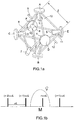
- the figure 1a illustrates in perspective view the three optical cavities of a triaxial gyrometer according to the prior art.
- the gyrometer comprises six mirrors A, B, C, D, E and F.
- the mirrors A, B, C, D, E and F are connected in pairs by optical paths AC, AD, AE, AF, BC, BD , BE, BF, CD, CF, ED and EF of the same length l, these optical paths allowing the propagation of light waves.
- Reserves 1, 2, 3, 4, 5 and 6 of the amplifying gas are arranged against the mirrors A, B, C, D, E and F respectively.
- the polyhedron formed by the six mirrors and the twelve optical paths is inscribed in a cube, each of the mirrors coinciding with the center of a face of said cube.
- the mirrors B, C and D are translatable, that is to say that they are mobile in translation. Thanks to a piezoelectric control, they can be moved away from or close to the center of the polyhedron by approximately 1 micrometer. In this way, the respective lengths of the three optical cavities X, Y and Z can be adjusted around the L value with an accuracy of about 0.01 micrometer.
- each of the optical cavities X, Y and Z depends on the position of two movable mirrors among B, C and D. It should also be noted that the position of each of the movable mirrors B, C and D conditions the length of two optical cavities among X, Y and Z.
- the mirrors A, E and F constitute the output couplers: they allow measurements of laser intensity. In this way, the respective powers of the waves traveling through the three optical cavities X, Y and Z can be measured.
- a cathode 7 connected by three capillaries to the gas reserves 2, 3 and 4 and six anodes 8, 9, 10, 11, 12 and 13 make it possible to excite the amplifying gas in the optical cavities X, Y and Z and thus to generate laser waves that traverse the optical cavities X, Y and Z.
- the three optical cavities X, Y and Z can be made by first digging the paths AC, AD, AE, AF, BC, BD, BE, BF, CD, CF, ED and EF in a block of a material characterized by controlled thermal expansion, for example the zerodur® material which offers a very high thermal expansion low. Then the mirrors A, B, C, D, E and F and the gas reserves 1, 2, 3, 4, 5 and 6 can be integrated in the block.
- the figure 1b illustrates by a synoptic the laser modes of any of the optical cavities X, Y or Z of the gyrometer of the figure 1a .
- the x-axis represents the optical frequency.
- the length L of the optical cavity determines the frequencies of the laser modes that it can emit: this set of frequencies consists of a multiple frequency comb of c / L, for example (m-2) xc / L, ( m-1) xc / L, mxc / L and (m + 1) xc / L where m is an integer.
- the length of each cavity is adjusted to bring a mode as close as possible to the maximum M of the laser gain of the amplifying gas, the spectrum of the gain being represented by a parabolic curve .
- the mode m corresponding to the frequency mxc / L which is substantially at the maximum gain.
- the optical characteristics of the gyrometer also change, they change the more as the deviation of the mode m from the maximum M increases.
- the gyrometer must therefore implement an autonomous device called "tuning cavity length" (ALC), which maintains the mode m closer to the maximum M.
- ALC automatic cavity length
- an ALC device can for example be obtained with a photodiode measuring the emitted laser power and a servo electronics that controls the movable mirror to maintain maximum transmitted power.
- each cavity can no longer be granted independently of the other two.
- a movable mirror generally consists of at least one membrane bonded to a transducer based on piezoelectric ceramics. Ceramics are usually controlled in positive and negative voltage, controls under which they deform by driving the membrane. The deformation of the membrane exerts a mechanical stress pushing or pulling on the center of the mirror. Thus the mirror moves in one direction or the other following a translational movement. Subsequently, the commands will be considered in the form of voltages denoted V B , V C and V D such that the displacements L B L C and L D of the mirrors B, C and D respectively are proportional to these voltages.
- the lengths L X , L Y and L Z of the three cavities are connected to the offsets of the mirrors L B , L C and L D according to the system of equations ⁇
- the X The X 0 + The D + The B
- the Y The Y 0 + The B + The C
- the X The Y The Z The X 0 The Y 0 The Z 0 + G ⁇ 0 1 1 1 0 1 1 1 0 V C V D V B
- V C V D V B 1 2 ⁇ G - 1 1 1 1 - 1 1 1 1 - 1 The X The Y The Z - The X 0 The Y 0 The Z 0
- the ALC device determines the position L X, Y, Z of the current laser mode with respect to the position The X , Y , Z Max corresponding to the maximum gain and reacts to reduce the gap. For example, it may be chosen to implement a modulation of mobile mirrors and a synchronous demodulation of the measured powers.
- the signals S X , S Y , S Z , I X , I Y and I Z can be sampled and the matrix operation performed by software.
- the output commands are then obtained by amplifying the voltages generated by a digital-to-analog converter. It is also possible not to use conversion of these signals to perform the hardware operation.
- the output commands are then obtained by amplifying the voltages resulting from the hardware operation. In all cases, the device samples the values I X , I Y and I Z to be able to monitor them.
- the laser power periodically varies as a function of L: the laser power passes through a maximum and a minimum whenever L varies by a length of d optical wave denoted ⁇ .
- the length of each cavity varies with the controls V B , V C and V D. In the example chosen, the variation is expressed according to: ⁇
- the X The X 0 + G V D + V B
- the Y The Y 0 + G V B + V C
- the Z The Z 0 + G V C + V D .
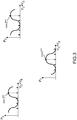
- the figure 2 illustrates an example of evolution of the laser powers P X , P Y and P Z emitted by the cavities X, Y and Z respectively as a function of the control voltages V B , V C and V D applied to the mirrors B, C and D respectively of the triaxial gyro of the figure 1a .
- the multiple frequency comb of c / L scrolls with respect to the spectrum of the gain represented by the parabolic curve .
- the intensity and thus the power emitted by this cavity increases when a frequency multiple of c / L approaches the maximum M, then decreases when this frequency multiple of c / L moves away from the maximum M.
- the power emitted by the cavity increases when a mode approaches the maximum M, then decreases when this mode moves away from the maximum M.
- the modes go in and out of the gain spectrum one after the other when the comb scrolls with respect to the gain spectrum, the power varies periodically.
- each of the power maxima corresponds to a mode or a frequency that is multiple of c / L.
- This explains the phenomenon of "jump mode": by varying L to maximize the power emitted, it is possible to switch from one mode to another.
- mode changes are to be avoided during operation of the gyrometer.
- a mode must be chosen at the start of the gyrometer, then it must be arranged to stay as close to the maximum power of this mode throughout the operation of the gyrometer.
- the mode may be different depending on the external temperature conditions and depending on the initial position of the moving mirrors. It should also be noted that, from one cavity to another, the mode may be different.
- the figure 2 also illustrates magnitudes K B , K C and K D which are the variations of the voltage commands on the mirrors B, C and D respectively which make it possible to change the lengths of the cavities X, Y and Z by an optical length ⁇ .
- K B , K C and K D are the variations of the voltage commands on the mirrors B, C and D respectively which make it possible to change the lengths of the cavities X, Y and Z by an optical length ⁇ .
- the mobile mirrors have substantially the same translation / electrical gain coefficient G, their small differences can be integrated over a large displacement of the order of ⁇ , considering that the quantities K B , K C and K D may vary from mirror to mirror
- the geometry of the triaxial cavity makes it possible to ensure that these values remain independent of the cavity concerned: ⁇
- the Y + ⁇ The Y 0 + G V B + K
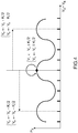
- the figures 4 and 5 illustrate two properties of X, Y and Z cavities of the same K-intermode of the triaxax gyrolaser of the figure 1a , by means of an example of evolution of the laser power emitted by the cavity X as a function of the sum of the two control voltages on which it depends, ie V D + V B.
- the first property is that the three cavities all remain on a maximum of gain when all the piezoelectric voltages are changed by a half-intermode K / 2. This first property is illustrated by the figure 4
- the second property is that the three cavities all remain on a maximum of gain when only one of the piezoelectric control voltages is changed by a complete intermode K. This second property is illustrated by the figure 5 with regard to cavity X.
- the invention proposes to modify the generation of the signal that controls the movement of the moving mirrors at the start of a triaxial laser gyrometer, so as to have a programmable offset control independent of the autonomous ALC. It should be noted that the invention also applies to any device comprising ring optical cavities, as long as the power of the light waves traveling through said optical cavities depends on the position of mobile mirrors.
- the laser gyrometer is only given as an example.
- the invention also proposes to have information in the control chain of the mirrors so as to be able to go back to their position when the autonomous servocontrol operates.
- a temperature sensor can be used to estimate the temperature of the gyrolaser, such as a thermistor or a thermocouple for example.
- a principle of the invention is to control the controls by following a linear ramp or a more complex profile to identify the power maxima simultaneously on the three laser cavities, so that the three movable mirrors can then be positioned simultaneously at positions that satisfy the more preferably the selected operating criteria.
- the values I X , I Y and I Z can be canceled artificially and the commands D X , D Y and D Z can be controlled by software.
- the device has a sampling of I X , I Y and I Z values in order to be able to monitor them.
- the control signals of the moving mirrors V B , V C and V D are then expressed according to the software commands D X , D Y and D Z :
- V C V D V B - AT - 1 1 1 1 - 1 1 1 1 - 1 D X D Y D Z
- a variation of the commands D X , D Y and D Z makes it possible to control the moving mirrors (according to a linear ramp or a more complex profile) and to simultaneously scan each of the three cavities in at least one mode.
- the laser powers emitted by the three cavities can be acquired.
- Values D X Max , D Y Max and D Z Max for which the intensities emitted are maximum respectively for the cavities X, Y and Z can then be stored. After scanning, simply assign the offset commands the values D X Max , D Y Max and D Z Max memorized to position the three mirrors as close to the power maxima as possible for the three cavities.
- This example does not restrict the method required to control mobile mirrors. Any technique corresponding to a bijection between the shift control and the command received by the mirrors is appropriate: it is sufficient to be able to program an independent scan for each mirror and then each can be placed on a calculated final position.
- V C V D V B - AT - 1 1 1 1 - 1 1 1 1 - 1 I X I Y I Z + D C ' D D ' D B ' with the ability to artificially cancel the values I x , I Y and I Z and to control the commands by software D C ' , D D ' and D B ' .
- the invention also proposes to be able to determine the position of the mirrors when autonomous servoing operates.
- the controls of the mirrors can be determined by a measurement of the values V B , V C and V D generated or from the values I X, Y, Z + D X , Y , Z which can be measured independently or known directly in the case of software-driven operations.
- the mirror controls can also be determined by measuring generated V B , V C and V D values. They can also be estimated from the values I X , I Y and I Z as well as D C ' , D D ' and D B ' measured independently or known directly in the case of software-driven operations.
- the quantity A can be assumed to be a known constant or it can be extracted from a table that matches values of A to temperature values, for example.
- the initial scan is not restricted to a linear ramp but may have a more complex shape to improve positioning in terms of accuracy, reproducibility or speed.
- the final positioning of the mobile mirrors can be chosen from several possibilities to improve the positioning, to take into account the particularities of each mirror, to influence their behavior or to compensate for certain effects.
- To scan a mode of a chosen laser cavity it suffices to apply on one of the two mobile mirrors a variation of its control of the value K, for example a sweep of the control of ⁇ K / 2 around a average value.
- By simultaneously scanning the two movable mirrors of this cavity it suffices to apply for each a variation of ⁇ K / 4. In this way, a simultaneous scanning of the three movable mirrors on a variation of ⁇ K / 4 around a mean value makes it possible to scan in one mode the three cavities of the triaxed laser gyro.
- the accuracy of the final positioning is determined by a compromise between the reduction of the scanning pitch, the noise level in the power measurements and the number of acquisition repetitions at each point.
- This control of the movable mirrors improves the determination of the initial positioning of the moving mirrors: the sequence and the control make it possible to have a fast positioning and for sure maximum of the laser gain simultaneously for the three cavities.
- V D 0 AT - D X 0 + D Y 0 - D Z 0
- the accuracy of the final positioning is also determined by a compromise between the scan pitch whose accuracy can be increased by increasing the number of sampled points along the scan, the noise level in the power measurements and the number of repetitions. acquisition at each point. In fact, repeating the acquisitions at the same point makes it possible to reduce the contribution of the noise but increases the total duration of the scanning.
- This control of mobile mirrors further improves the determination of the positioning of mobile mirrors: the sequence and the control allow to have a fast positioning, customizable in function of the moving mirror and certainly maximum laser gain simultaneously for the three cavities.
- the choice of scanning and positioning ranges as a function of the initial temperature can make it possible to anticipate variations in the behavior of the moving mirrors.
- V B final > V B 0 + K / 2 ⁇ ⁇ V C final ⁇ V C 0 - K / 2 ; V C 0 V D final ⁇ V D 0 - K / 2 ; V D 0 V B final ⁇ V B 0 - K / 2 ⁇ ⁇ V C final ⁇ V C 0 ; V C 0 + K / 2 V D final ⁇ V D 0 ; V D 0 + K / 2
- the invention proposes in particular to use the first property of triaxed laser cavities illustrated by the figure 4 to shift all the controls of the mirrors by keeping the cavities near a maximum of gain.
- the proposed modification of the commands can redefine values in the interval K / 2, these values simultaneously bringing the three cavities closer to their maximum gain.
- the invention also proposes to use the second property of the triaxial laser cavities illustrated by the figure 5 to shift the control of a single mirror by keeping all the cavities near a maximum of gain. By shifting the mirror at the end of the range of a complete intermode, it is brought back to the median value of the interval.
- K ( K B + K C + K D ) / 3
- the values of the mirror commands simultaneously bringing the three cavities near a maximum of gain are therefore automatically found in intervals whose centers V B 0 , V C 0 and V D 0 are mirror-specific but with the same amplitude ⁇ 3 K / 4 calculated on the average of the intermodes of the three mirrors.
- the control example of the moving mirrors illustrated by equation 9 leads to the same results.
- the controls can therefore be driven in intervals of different centers and amplitudes and the moving mirrors then positioned simultaneously in intervals clean, of distinct centers but of the same width. This method does not reduce the solution range for the lower intermode mirror. It is the refocusing procedure that can then be performed that can bring the controls of the mirrors in a range of amplitude equal to their intermode.
- V C 0 + K C - K B / 4 V D final ⁇ V D 0 - 2 K C + K D - K B / 4 ;
- V D 0 + K D - K B / 4 V B final ⁇ V B 0 - K B / 2 ⁇ ⁇ V C final ⁇ V C 0 - K C - K B / 4 ;
- V D 0 + 2 K C + K C + K C + K C - K B / 4 V D final ⁇ V D 0 - K D - K B / 4 ;
- the proposed invention makes it possible to take into account the thermal behavior of each of the mobile mirrors in their positioning at the start of the laser gyro.
- the environment in which it is used can bring significant thermal variations.
- the optical block and the fixing mechanisms deform and induce a variation in the optical lengths of the laser cavities.
- the autonomous servo electronics maintain the perimeters of the cavities constant and at maximum gain by adjusting the values of the controls of the moving mirrors.
- the term "thermal behavior" of a moving mirror will be called the variation of its control due to autonomous servoing when the laser gyro is kept in operation and undergoes a thermal variation equal to its full range of use.
- the figure 6 illustrates by a graph the control variations of the mirrors B, C and D observable in function of a positive thermal gradient.
- the mirror B has a large positive variation: its control is globally increasing with a global maximum possibly below the maximum temperature.
- the mirror D shows a large negative variation: its control is globally decreasing with a minimum possibly below the maximum temperature.
- the mirror C has a small variation: its control has an extremum in the middle of the temperature range, which can be a maximum as illustrated by the figure 6 but just as well a minimum.
- the invention can in particular make it possible to use the information of a temperature sensor to adapt the scanning and positioning range of each mobile mirror during the sequence.
- a preliminary characterization can make it possible to evaluate the thermal behaviors of each mirror.
- Temperature thresholds can then be determined, either by a compromise between the characteristics of the mirrors, or by a more general compromise around the laser gyro, these thresholds being able to be stored in tables. It can then be defined, for each mirror and for each start temperature threshold, a positive variation ⁇ Vpos possible on its control and a negative variation ⁇ Vnég.
- a possible positioning range of each mirror may be chosen, selecting its center so that it remains in the range of validity of the autonomous servocontrol.
- the invention can thus make it possible to take into account the thermal and dynamic behavior of each of the mobile mirrors.
- the invention may also make it possible to promote the orientation of the movement of each of the mirrors.
- the positioning range can be chosen to favor a control such that the translation mechanism pushes the mirror more often than it pulls it.
- the device may also facilitate operation by pulling or operation centered around a predetermined value.
- the invention can also make it possible to reduce the total variation of the commands during operation and thus to reduce the required control domain. In the case where the mirrors are controlled in tension, the invention can make it possible to avoid the use of high voltages and avoid mode jumps during operation after start sequence.
- the proposed invention can also make it possible to take into account the hysteresis phenomenon in the positioning of mobile mirrors and to reduce its influence.
- the positioning sequences described above assume a reproducibility of the movement of the mirrors with their control.
- V B , V C or V D the mirrors are always geometrically offset by the same quantity L B , L C or L D according to equation 1.
- materials that exhibit mechanical hysteresis may be used.
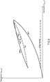
- the translation of the mirror is then no longer linear with its command and its response has a characteristic of the type illustrated by the figure 7 .
- the mirrors are controlled towards a position marked with a maximum of gain, for example by moving the mirror back following a positioning displacement PM of the mirror.
- the response hysteresis introduces a positioning difference E between the position requested and the position actually reached by the mirrors at the end of their translations.
- the accumulation of these gaps between the mirrors of the three cavities can lead to positioning the laser cavities significantly away from the expected maxima of gain.
- the figure 8 illustrates a case where the ramp is increasing with a positive mean value.
- Preliminary exploration of the range provided by displacements DP1 and DP2 may make it possible to reduce the hysteresis of the moving mirror to a positioning distance E '.
- the pre-scan can be done by traversing the range in one direction followed by an increasing or decreasing ramp.
- the positioning gap can then be reduced by a factor of two.
- the beach can also be covered by a full round trip and followed by a ramp increasing or decreasing.
- the positioning gap is reduced by a factor of three to four. Several round trips can be made to reduce the positioning gap by below a desired amount.
- the proposed invention can thus take into account the hysteresis phenomenon in the positioning of mobile mirrors and reduce its influence.
- the scanning range extending over ⁇ ⁇ / 4 can then be explored, for example by following an increasing ramp.
- the repositioning can still have improved reproducibility if its initial state is comparable to that preceding the scan.
- the mirrors can be re-driven in a sequence comparable to that of the pre-scan to bring them to the pre-scan start value.
- the sequence can be of the type illustrated by the figure 9 to optimize the hysteresis reduction cycle.
- a displacement DP'1 carries out a pre-scan to go to the end of the complete range, ie on ⁇ ⁇ / 2.
- a DP'2 move performs a pre-scan back to the beginning of the full range.
- a displacement DP'3 realizes a positioning at the beginning of the scanning range.
- a DP'4 displacement performs a scan on ⁇ ⁇ / 4.
- DP'5 displacement achieves positioning at the end of the full positioning range.
- a DP'6 move returns to the beginning of this range.
- the movable mirrors are then ready to receive their final command for a reduced positioning gap because the homing and the measuring ramp use the same side of the hysteresis cycle.
- the invention can therefore allow the gyrolaser to start simultaneously positioning the three movable mirrors as close to a maximum gain of the three cavities, whatever their intermodes, in intervals of selected amplitudes and with a desired accuracy.
- the autonomous cavity length control can be started. It allows, with its own convergence time constant, to join the cavities more finely to their maximum intensity and to maintain them there. It is now necessary to show that it is advantageously possible to perform a test at the end of the convergence period of the autonomous servocontrol to verify the smooth running of the sequences according to the invention described above.
- Mirror control indications can be read at the end of the autonomous servo convergence and compared to the expected range. The difference between the position of each mirror and the center of its positioning range can be calculated.
- V D 0 AT - D X 0 + D Y 0 - D Z 0
- V B - V B 0 - AT I X + D X - D X 0 + I Y + D Y - D Y 0 - I Z - D Z + D Z 0
- the invention described above still has the main advantages that it avoids the problem of fashion competition. Furthermore, no longer implicitly assuming a similar mechanical behavior of the mirrors as a function of temperature, the present invention allows greater tolerance on the differences in behavior between the mirrors. As a result, fewer mirrors are sent to the end of the production line. The cost savings are not negligible.
Landscapes
- Physics & Mathematics (AREA)
- Engineering & Computer Science (AREA)
- Optics & Photonics (AREA)
- Electromagnetism (AREA)
- Power Engineering (AREA)
- General Physics & Mathematics (AREA)
- Radar, Positioning & Navigation (AREA)
- Remote Sensing (AREA)
- Lasers (AREA)
- Gyroscopes (AREA)
Claims (7)
- Verfahren zur Positionierung von drei verschiebbaren Spiegeln (B, C, D) in einem Lasergyrometer, das drei Ringlaserhohlkammem aufweist, wobei die Positionierung beim Einschalten des Gyrometers durchgeführt wird, wobei jede der drei Laserhohlkammern aufweist:- ein optisches Verstärkermedium, das angeregt werden kann, um Lichtwellen zu erzeugen;- eine optische Hohlkammer (X, Y, Z), die durch eine Gesamtheit von Spiegeln (A, B, C, D, E, F) gebildet wird, die zwei der verschiebbaren Spiegel einschließen, wobei die Länge der optischen Hohlkammer von der Position der beiden verschiebbaren Spiegel abhängt, wobei die beiden verschiebbaren Spiegel in Positionsbereiche verlagert werden können, die der optischen Hohlkammer Längen verleihen, für die das Verstärkermedium mindestens eine Laserwelle erzeugt, wobei die Spiegel durch elektrische Spannungen derart gesteuert werden, dass ihre Verschiebungen proportional zu diesen Spannungen sind;wobei jeder der drei verschiebbaren Spiegel in die Ausformung von zwei der drei optischen Hohlkammern eingeht, wobei das Verfahren dadurch gekennzeichnet wird, dass es aufweist:- eine Phase der Vorpositionierung der drei Spiegel in einer Anfangsdreiergruppe von jeweils vorgegebenen Positionen;- eine gleichzeitige Linearverschiebungsphase der drei Spiegel in Bereichen mit einer selben Größe kleiner oder gleich der Zwischenmode der optischen Hohlkammer mit der stärksten Zwischenmode (KB, KC, KD), um sicherzustellen, dass jede der optischen Hohlkammern eine Länge durchläuft, für die das Verstärkermedium eine Höchstverstärkung (M) bietet, wobei die Intensitäten der Laserwellen, die jeweils durch jede der optischen Hohlkammern gehen, für jede durch die Spiegel eingenommene Dreiergruppe der Positionen gemessen werden, wobei die Zwischenmode als die Steuerungsänderung der Spannung auf einem der Spiegel definiert wird, die die Länge der entsprechenden Hohlkammer um eine optische Wellenlänge λ zu ändern erlaubt;- eine Bestimmungsphase der Länge jeder der drei Hohlkammern, für die die Hohlkammer eine Höchstintensität liefert, anhand der drei Dreiergruppen der Spiegelpositionen, die jeder der drei Hohlkammern jeweils erlaubt haben, eine Höchstintensität zu liefern;- eine Bestimmungsphase einer endgültigen Dreiergruppe von Spiegelpositionen, die erlaubt, den drei Hohlkammern gleichzeitig die Längen zu verleihen, für die sie eine Höchstintensität liefern;- eine Positionierungsphase der Spiegel zu der endgültigen Positionsdreiergruppe.
- Verfahren nach Anspruch 1, dadurch gekennzeichnet, dass die Anfangsdreiergruppe von Positionen der drei Spiegel (B, C, D) aus einer Tabelle extrahiert wird, die dazu führt, dass die Anfangsdreiergruppe von Spiegelpositionen den Temperaturwerten entspricht, die jeder der optischen Hohlkammern (X, Y, Z) jeweils eine Länge verleiht, für die das Verstärkermedium eine Höchstverstärkung (M) für die Temperatur bietet.
- Verfahren nach Anspruch 1, dadurch gekennzeichnet, dass die Verstärkermedien durch eine elektrische Entladung ionisierbare Gase sind.
- Verfahren nach Anspruch 1, dadurch gekennzeichnet, dass das Gyrometer ein Triaxial-Gyrometer ist.
- Verfahren nach Anspruch 1, wobei die drei optischen Hohlkammern (X, Y, Z) eine selbe Zwischenmode (K) haben, dadurch gekennzeichnet, dass die Größe der Verschiebung der drei Spiegel (B, C, D) gleich der Hälfte der Zwischenmode ist.
- Verfahren nach Anspruch 1, dadurch gekennzeichnet, dass es eine Vorphase der Abtastung der drei Spiegel (B, C, D) in den Bereichen aufweist, die die Verschiebungsbereiche der Spiegel abdecken, ohne aber die Intensitäten der Wellen zu messen, um die Hysterese zwischen der Verschiebungsphase der Spiegel und der Positionierungsphase der Spiegel zu verringern.
- Verfahren nach Anspruch 1, wobei das Gyrometer einen Anpassungsmechanismus aufweist, der es erlaubt, ausgehend von der endgültigen Dreiergruppe der Positionen, die Positionen der verschiebbaren Spiegel (B, C, D) dauerhaft anzupassen, um sicherzustellen, dass die Hohlkammern (X, Y, Z) jeweilige Längen haben, die ihnen erlauben, dauerhaft eine Höchstintensität zu liefern, dadurch gekennzeichnet, dass das Verfahren eine Endphase des Vergleichs der endgültigen Dreiergruppe der Positionen mit einer Dreiergruppe der Positionen aufweist, zu der der Anpassungsmechanismus nach einer bestimmten Verzögerung ein Konvergieren der Spiegel bewirkt, wobei die vorhergehenden Phasen des Verfahrens wiederholt werden und/oder die Differenz gespeichert wird und/oder die Vorrichtung abgeschaltet wird, wenn einer der Spiegel sich von der Position entfernt hat, die er über einen gegebenen Schwellenwert hinaus am Ende der Positionierungsphase hatte.
Applications Claiming Priority (2)
| Application Number | Priority Date | Filing Date | Title |
|---|---|---|---|
| FR0800837A FR2927698B1 (fr) | 2008-02-15 | 2008-02-15 | Methode de positionnement des miroirs d'un gyrometre laser triaxe, notamment au demarrage du gyrometre |
| PCT/EP2009/051566 WO2009101105A1 (fr) | 2008-02-15 | 2009-02-11 | Methode de positionnement des miroirs d'un gyrometre laser triaxe, notamment au demarrage du gyrometre |
Publications (2)
| Publication Number | Publication Date |
|---|---|
| EP2242992A1 EP2242992A1 (de) | 2010-10-27 |
| EP2242992B1 true EP2242992B1 (de) | 2019-05-08 |
Family
ID=39924970
Family Applications (1)
| Application Number | Title | Priority Date | Filing Date |
|---|---|---|---|
| EP09710391.5A Active EP2242992B1 (de) | 2008-02-15 | 2009-02-11 | Verfahren zur positionierung des spiegels eines dreiachsigen lasergyrometers, insbesondere bei der inbetriebnahme des gyrometers |
Country Status (6)
| Country | Link |
|---|---|
| US (1) | US8493566B2 (de) |
| EP (1) | EP2242992B1 (de) |
| CN (1) | CN102007372B (de) |
| FR (1) | FR2927698B1 (de) |
| RU (1) | RU2493642C2 (de) |
| WO (1) | WO2009101105A1 (de) |
Families Citing this family (4)
| Publication number | Priority date | Publication date | Assignee | Title |
|---|---|---|---|---|
| US8659760B2 (en) * | 2012-04-12 | 2014-02-25 | Honeywell International Inc. | Resonator fiber optic gyroscope utilizing laser frequency combs |
| USD922223S1 (en) * | 2019-06-14 | 2021-06-15 | Ying Xu | Gyroscope |
| USD1024811S1 (en) * | 2022-07-11 | 2024-04-30 | Tedco Inc | Gyroscope |
| FR3167722A1 (fr) | 2024-10-18 | 2026-04-24 | Thales | Coeur inertiel pour unité de mesure inertielle et unité de mesure inertielle associée |
Family Cites Families (15)
| Publication number | Priority date | Publication date | Assignee | Title |
|---|---|---|---|---|
| FR2512198A1 (fr) * | 1980-03-21 | 1983-03-04 | Sfena | Gyrometre laser triaxial, monobloc, compact a six miroirs |
| US4585346A (en) * | 1983-03-17 | 1986-04-29 | The Singer Company | Pathlength controller for three-axis ring laser gyroscope assembly |
| EP0130766B1 (de) * | 1983-06-29 | 1990-01-31 | British Aerospace Public Limited Company | Mehrachsiger Ringlaserkreisel |
| US5357338A (en) * | 1983-07-11 | 1994-10-18 | Litton Systems, Inc. | Path length controller with offset bias for a ring laser gyro |
| US4755057A (en) * | 1984-10-02 | 1988-07-05 | Litton Systems, Inc. | Path length control method for ring laser gyroscope |
| US4839903A (en) * | 1985-06-27 | 1989-06-13 | British Aerospace Public Limited Company | Ring laser gyroscopes |
| US5363194A (en) * | 1992-08-18 | 1994-11-08 | Honeywell Inc. | Laser gyro microprocessor start up control method and apparatus |
| US5309459A (en) * | 1992-10-20 | 1994-05-03 | Honeywell, Inc. | Laser gyro smart digital PLC acquisition control |
| US5450198A (en) * | 1993-10-01 | 1995-09-12 | Honeywell Inc. | Laser gyro microprocessor based smart mode acquisition and high performance mode hopping |
| FR2759162B1 (fr) * | 1997-02-05 | 1999-04-30 | Sextant Avionique | Dispositif de fixation du bloc optique d'un gyrometre laser triaxial sur un dispositif d'activation |
| FR2759160B1 (fr) * | 1997-02-05 | 1999-04-23 | Sextant Avionique | Gyrometre laser triaxial symetrise par rapport a son axe d'activation |
| RU2124185C1 (ru) * | 1997-05-13 | 1998-12-27 | Михаил Афанасьевич Новиков | Оптический гироскоп с пассивным кольцевым резонатором |
| CN100424470C (zh) * | 2004-10-28 | 2008-10-08 | 金世龙 | 一种激光陀螺调腔方法及其使用的光路程长控制镜 |
| FR2902870B1 (fr) * | 2006-06-23 | 2008-09-05 | Thales Sa | Dispositif d'amelioration de la duree de vie d'un gyrometre triaxial |
| CN100481655C (zh) * | 2007-06-12 | 2009-04-22 | 中国人民解放军国防科学技术大学 | 基于随机并行优化算法的激光谐振腔快速调腔方法 |
-
2008
- 2008-02-15 FR FR0800837A patent/FR2927698B1/fr not_active Expired - Fee Related
-
2009
- 2009-02-11 WO PCT/EP2009/051566 patent/WO2009101105A1/fr not_active Ceased
- 2009-02-11 US US12/919,980 patent/US8493566B2/en active Active
- 2009-02-11 CN CN2009801133807A patent/CN102007372B/zh active Active
- 2009-02-11 RU RU2010138116/28A patent/RU2493642C2/ru not_active IP Right Cessation
- 2009-02-11 EP EP09710391.5A patent/EP2242992B1/de active Active
Non-Patent Citations (1)
| Title |
|---|
| None * |
Also Published As
| Publication number | Publication date |
|---|---|
| RU2493642C2 (ru) | 2013-09-20 |
| CN102007372B (zh) | 2013-07-31 |
| US8493566B2 (en) | 2013-07-23 |
| RU2010138116A (ru) | 2012-03-20 |
| CN102007372A (zh) | 2011-04-06 |
| FR2927698A1 (fr) | 2009-08-21 |
| US20110116097A1 (en) | 2011-05-19 |
| EP2242992A1 (de) | 2010-10-27 |
| WO2009101105A1 (fr) | 2009-08-20 |
| FR2927698B1 (fr) | 2010-12-24 |
Similar Documents
| Publication | Publication Date | Title |
|---|---|---|
| EP0430747B1 (de) | Fiberoptische Messeinrichtung, Gyroskop und Einrichtung zur Navigation und Stabilisation | |
| EP0455530B1 (de) | Faseroptische Messeinrichtung, Gyrometer, Navigations- und Stabilisierungssystem, Stromsensor | |
| WO2017220922A1 (fr) | Système de mesure et gyromètre comportant un tel système | |
| FR2680241A1 (fr) | Systeme de commande de longueur de la cavite d'un gyroscope a laser en anneau a multi-oscillateur. | |
| EP0027763A1 (de) | Verfahren und Apparat zur Abstandsmessung durch Laserinterferometrie mit zwei Wellenlängen | |
| WO2009101105A1 (fr) | Methode de positionnement des miroirs d'un gyrometre laser triaxe, notamment au demarrage du gyrometre | |
| WO2014128027A1 (fr) | Capteur a accelerometre pendulaire electrostatique et procede de commande d'un tel capteur | |
| WO2004094952A1 (fr) | Gyrolaser a etat solide stabilise | |
| EP2817590B1 (de) | Faseroptische messungsvorrichtung, gyrometer und navigations- sowie trägheitsstabilisierungssystem | |
| EP1797396B1 (de) | Skalenfaktorstabilisierter festkörper-laserkreisel | |
| EP0656545A1 (de) | Magnetometer mit polarisiertem Licht und gekoppeltem Hochfrequenzfeld | |
| EP3370077B1 (de) | Magnetometer mit isotroper optischer pumpfunktion | |
| EP0359666B2 (de) | Fiberoptische Messeinrichtung, Gyrometer, Navigations- und Stabilisationssystem | |
| EP0553028B1 (de) | Resonanz-Magnetometer mit optischen Pumpen, das einen monolithischen Laser verwendet | |
| FR2672393A1 (fr) | Capteur de vitesse angulaire a laser en anneau et procede pour le faire fonctionner. | |
| EP0331581A1 (de) | Piezoelektrischer Spiegel für Laserkreisel | |
| EP2267408A1 (de) | Stabilisiert Festkörperlaserkreisel | |
| WO2009103900A2 (fr) | Procede de correction de gain d'un organe capacitif et dispositif de mise en oeuvre | |
| FR2765964A1 (fr) | Dispositif optique de mesure de distance avec une grande precision | |
| FR2634552A1 (fr) | Gyrometres a lasers redondants | |
| FR2630551A1 (fr) | Miroir piezoelectrique compense pour gyrometre a laser | |
| FR2599514A1 (fr) | Systeme opto-electronique pour la determination de la direction et de la vitesse d'un vehicule mobile | |
| WO2009141221A2 (fr) | Gyrolaser a grand facteur d'échelle | |
| WO1988006276A2 (fr) | Gyrometre laser, dispositif de suppression des rotations parasites des miroirs mobiles |
Legal Events
| Date | Code | Title | Description |
|---|---|---|---|
| PUAI | Public reference made under article 153(3) epc to a published international application that has entered the european phase |
Free format text: ORIGINAL CODE: 0009012 |
|
| 17P | Request for examination filed |
Effective date: 20100813 |
|
| AK | Designated contracting states |
Kind code of ref document: A1 Designated state(s): AT BE BG CH CY CZ DE DK EE ES FI FR GB GR HR HU IE IS IT LI LT LU LV MC MK MT NL NO PL PT RO SE SI SK TR |
|
| AX | Request for extension of the european patent |
Extension state: AL BA RS |
|
| RIN1 | Information on inventor provided before grant (corrected) |
Inventor name: VAUZELLE, PATRICK Inventor name: THIBAUDEAU, LAURENT Inventor name: BONNAUDET, ETIENNE Inventor name: GUTTY, FRANCOIS |
|
| DAX | Request for extension of the european patent (deleted) | ||
| STAA | Information on the status of an ep patent application or granted ep patent |
Free format text: STATUS: EXAMINATION IS IN PROGRESS |
|
| 17Q | First examination report despatched |
Effective date: 20170731 |
|
| GRAP | Despatch of communication of intention to grant a patent |
Free format text: ORIGINAL CODE: EPIDOSNIGR1 |
|
| STAA | Information on the status of an ep patent application or granted ep patent |
Free format text: STATUS: GRANT OF PATENT IS INTENDED |
|
| INTG | Intention to grant announced |
Effective date: 20180517 |
|
| RAP1 | Party data changed (applicant data changed or rights of an application transferred) |
Owner name: THALES |
|
| GRAS | Grant fee paid |
Free format text: ORIGINAL CODE: EPIDOSNIGR3 |
|
| GRAA | (expected) grant |
Free format text: ORIGINAL CODE: 0009210 |
|
| STAA | Information on the status of an ep patent application or granted ep patent |
Free format text: STATUS: THE PATENT HAS BEEN GRANTED |
|
| AK | Designated contracting states |
Kind code of ref document: B1 Designated state(s): AT BE BG CH CY CZ DE DK EE ES FI FR GB GR HR HU IE IS IT LI LT LU LV MC MK MT NL NO PL PT RO SE SI SK TR |
|
| REG | Reference to a national code |
Ref country code: GB Ref legal event code: FG4D Free format text: NOT ENGLISH |
|
| REG | Reference to a national code |
Ref country code: CH Ref legal event code: EP Ref country code: AT Ref legal event code: REF Ref document number: 1130858 Country of ref document: AT Kind code of ref document: T Effective date: 20190515 |
|
| REG | Reference to a national code |
Ref country code: DE Ref legal event code: R096 Ref document number: 602009058223 Country of ref document: DE Ref country code: IE Ref legal event code: FG4D Free format text: LANGUAGE OF EP DOCUMENT: FRENCH |
|
| REG | Reference to a national code |
Ref country code: NL Ref legal event code: MP Effective date: 20190508 |
|
| REG | Reference to a national code |
Ref country code: LT Ref legal event code: MG4D |
|
| PG25 | Lapsed in a contracting state [announced via postgrant information from national office to epo] |
Ref country code: NO Free format text: LAPSE BECAUSE OF FAILURE TO SUBMIT A TRANSLATION OF THE DESCRIPTION OR TO PAY THE FEE WITHIN THE PRESCRIBED TIME-LIMIT Effective date: 20190808 Ref country code: PT Free format text: LAPSE BECAUSE OF FAILURE TO SUBMIT A TRANSLATION OF THE DESCRIPTION OR TO PAY THE FEE WITHIN THE PRESCRIBED TIME-LIMIT Effective date: 20190908 Ref country code: FI Free format text: LAPSE BECAUSE OF FAILURE TO SUBMIT A TRANSLATION OF THE DESCRIPTION OR TO PAY THE FEE WITHIN THE PRESCRIBED TIME-LIMIT Effective date: 20190508 Ref country code: HR Free format text: LAPSE BECAUSE OF FAILURE TO SUBMIT A TRANSLATION OF THE DESCRIPTION OR TO PAY THE FEE WITHIN THE PRESCRIBED TIME-LIMIT Effective date: 20190508 Ref country code: SE Free format text: LAPSE BECAUSE OF FAILURE TO SUBMIT A TRANSLATION OF THE DESCRIPTION OR TO PAY THE FEE WITHIN THE PRESCRIBED TIME-LIMIT Effective date: 20190508 Ref country code: NL Free format text: LAPSE BECAUSE OF FAILURE TO SUBMIT A TRANSLATION OF THE DESCRIPTION OR TO PAY THE FEE WITHIN THE PRESCRIBED TIME-LIMIT Effective date: 20190508 Ref country code: LT Free format text: LAPSE BECAUSE OF FAILURE TO SUBMIT A TRANSLATION OF THE DESCRIPTION OR TO PAY THE FEE WITHIN THE PRESCRIBED TIME-LIMIT Effective date: 20190508 Ref country code: ES Free format text: LAPSE BECAUSE OF FAILURE TO SUBMIT A TRANSLATION OF THE DESCRIPTION OR TO PAY THE FEE WITHIN THE PRESCRIBED TIME-LIMIT Effective date: 20190508 |
|
| PG25 | Lapsed in a contracting state [announced via postgrant information from national office to epo] |
Ref country code: BG Free format text: LAPSE BECAUSE OF FAILURE TO SUBMIT A TRANSLATION OF THE DESCRIPTION OR TO PAY THE FEE WITHIN THE PRESCRIBED TIME-LIMIT Effective date: 20190808 Ref country code: GR Free format text: LAPSE BECAUSE OF FAILURE TO SUBMIT A TRANSLATION OF THE DESCRIPTION OR TO PAY THE FEE WITHIN THE PRESCRIBED TIME-LIMIT Effective date: 20190809 Ref country code: LV Free format text: LAPSE BECAUSE OF FAILURE TO SUBMIT A TRANSLATION OF THE DESCRIPTION OR TO PAY THE FEE WITHIN THE PRESCRIBED TIME-LIMIT Effective date: 20190508 |
|
| REG | Reference to a national code |
Ref country code: AT Ref legal event code: MK05 Ref document number: 1130858 Country of ref document: AT Kind code of ref document: T Effective date: 20190508 |
|
| PG25 | Lapsed in a contracting state [announced via postgrant information from national office to epo] |
Ref country code: CZ Free format text: LAPSE BECAUSE OF FAILURE TO SUBMIT A TRANSLATION OF THE DESCRIPTION OR TO PAY THE FEE WITHIN THE PRESCRIBED TIME-LIMIT Effective date: 20190508 Ref country code: RO Free format text: LAPSE BECAUSE OF FAILURE TO SUBMIT A TRANSLATION OF THE DESCRIPTION OR TO PAY THE FEE WITHIN THE PRESCRIBED TIME-LIMIT Effective date: 20190508 Ref country code: DK Free format text: LAPSE BECAUSE OF FAILURE TO SUBMIT A TRANSLATION OF THE DESCRIPTION OR TO PAY THE FEE WITHIN THE PRESCRIBED TIME-LIMIT Effective date: 20190508 Ref country code: AT Free format text: LAPSE BECAUSE OF FAILURE TO SUBMIT A TRANSLATION OF THE DESCRIPTION OR TO PAY THE FEE WITHIN THE PRESCRIBED TIME-LIMIT Effective date: 20190508 Ref country code: EE Free format text: LAPSE BECAUSE OF FAILURE TO SUBMIT A TRANSLATION OF THE DESCRIPTION OR TO PAY THE FEE WITHIN THE PRESCRIBED TIME-LIMIT Effective date: 20190508 Ref country code: SK Free format text: LAPSE BECAUSE OF FAILURE TO SUBMIT A TRANSLATION OF THE DESCRIPTION OR TO PAY THE FEE WITHIN THE PRESCRIBED TIME-LIMIT Effective date: 20190508 |
|
| REG | Reference to a national code |
Ref country code: DE Ref legal event code: R097 Ref document number: 602009058223 Country of ref document: DE |
|
| PG25 | Lapsed in a contracting state [announced via postgrant information from national office to epo] |
Ref country code: IT Free format text: LAPSE BECAUSE OF FAILURE TO SUBMIT A TRANSLATION OF THE DESCRIPTION OR TO PAY THE FEE WITHIN THE PRESCRIBED TIME-LIMIT Effective date: 20190508 |
|
| PLBE | No opposition filed within time limit |
Free format text: ORIGINAL CODE: 0009261 |
|
| STAA | Information on the status of an ep patent application or granted ep patent |
Free format text: STATUS: NO OPPOSITION FILED WITHIN TIME LIMIT |
|
| PG25 | Lapsed in a contracting state [announced via postgrant information from national office to epo] |
Ref country code: TR Free format text: LAPSE BECAUSE OF FAILURE TO SUBMIT A TRANSLATION OF THE DESCRIPTION OR TO PAY THE FEE WITHIN THE PRESCRIBED TIME-LIMIT Effective date: 20190508 |
|
| 26N | No opposition filed |
Effective date: 20200211 |
|
| PG25 | Lapsed in a contracting state [announced via postgrant information from national office to epo] |
Ref country code: PL Free format text: LAPSE BECAUSE OF FAILURE TO SUBMIT A TRANSLATION OF THE DESCRIPTION OR TO PAY THE FEE WITHIN THE PRESCRIBED TIME-LIMIT Effective date: 20190508 |
|
| PG25 | Lapsed in a contracting state [announced via postgrant information from national office to epo] |
Ref country code: SI Free format text: LAPSE BECAUSE OF FAILURE TO SUBMIT A TRANSLATION OF THE DESCRIPTION OR TO PAY THE FEE WITHIN THE PRESCRIBED TIME-LIMIT Effective date: 20190508 |
|
| REG | Reference to a national code |
Ref country code: CH Ref legal event code: PL |
|
| GBPC | Gb: european patent ceased through non-payment of renewal fee |
Effective date: 20200211 |
|
| REG | Reference to a national code |
Ref country code: BE Ref legal event code: MM Effective date: 20200229 |
|
| PG25 | Lapsed in a contracting state [announced via postgrant information from national office to epo] |
Ref country code: MC Free format text: LAPSE BECAUSE OF FAILURE TO SUBMIT A TRANSLATION OF THE DESCRIPTION OR TO PAY THE FEE WITHIN THE PRESCRIBED TIME-LIMIT Effective date: 20190508 Ref country code: LU Free format text: LAPSE BECAUSE OF NON-PAYMENT OF DUE FEES Effective date: 20200211 |
|
| PG25 | Lapsed in a contracting state [announced via postgrant information from national office to epo] |
Ref country code: CH Free format text: LAPSE BECAUSE OF NON-PAYMENT OF DUE FEES Effective date: 20200229 Ref country code: LI Free format text: LAPSE BECAUSE OF NON-PAYMENT OF DUE FEES Effective date: 20200229 |
|
| PG25 | Lapsed in a contracting state [announced via postgrant information from national office to epo] |
Ref country code: GB Free format text: LAPSE BECAUSE OF NON-PAYMENT OF DUE FEES Effective date: 20200211 Ref country code: IE Free format text: LAPSE BECAUSE OF NON-PAYMENT OF DUE FEES Effective date: 20200211 |
|
| PG25 | Lapsed in a contracting state [announced via postgrant information from national office to epo] |
Ref country code: BE Free format text: LAPSE BECAUSE OF NON-PAYMENT OF DUE FEES Effective date: 20200229 |
|
| PGFP | Annual fee paid to national office [announced via postgrant information from national office to epo] |
Ref country code: DE Payment date: 20220118 Year of fee payment: 14 |
|
| PG25 | Lapsed in a contracting state [announced via postgrant information from national office to epo] |
Ref country code: MT Free format text: LAPSE BECAUSE OF FAILURE TO SUBMIT A TRANSLATION OF THE DESCRIPTION OR TO PAY THE FEE WITHIN THE PRESCRIBED TIME-LIMIT Effective date: 20190508 Ref country code: CY Free format text: LAPSE BECAUSE OF FAILURE TO SUBMIT A TRANSLATION OF THE DESCRIPTION OR TO PAY THE FEE WITHIN THE PRESCRIBED TIME-LIMIT Effective date: 20190508 |
|
| PG25 | Lapsed in a contracting state [announced via postgrant information from national office to epo] |
Ref country code: MK Free format text: LAPSE BECAUSE OF FAILURE TO SUBMIT A TRANSLATION OF THE DESCRIPTION OR TO PAY THE FEE WITHIN THE PRESCRIBED TIME-LIMIT Effective date: 20190508 Ref country code: IS Free format text: LAPSE BECAUSE OF FAILURE TO SUBMIT A TRANSLATION OF THE DESCRIPTION OR TO PAY THE FEE WITHIN THE PRESCRIBED TIME-LIMIT Effective date: 20190908 |
|
| P01 | Opt-out of the competence of the unified patent court (upc) registered |
Effective date: 20230427 |
|
| REG | Reference to a national code |
Ref country code: DE Ref legal event code: R119 Ref document number: 602009058223 Country of ref document: DE |
|
| PG25 | Lapsed in a contracting state [announced via postgrant information from national office to epo] |
Ref country code: DE Free format text: LAPSE BECAUSE OF NON-PAYMENT OF DUE FEES Effective date: 20230901 |
|
| PGFP | Annual fee paid to national office [announced via postgrant information from national office to epo] |
Ref country code: FR Payment date: 20260121 Year of fee payment: 18 |