EP2242543B1 - Reel lock for passenger restraint having dual locking positions - Google Patents
Reel lock for passenger restraint having dual locking positions Download PDFInfo
- Publication number
- EP2242543B1 EP2242543B1 EP09705749.1A EP09705749A EP2242543B1 EP 2242543 B1 EP2242543 B1 EP 2242543B1 EP 09705749 A EP09705749 A EP 09705749A EP 2242543 B1 EP2242543 B1 EP 2242543B1
- Authority
- EP
- European Patent Office
- Prior art keywords
- locking
- webbing
- locking bolt
- end plate
- shaft
- Prior art date
- Legal status (The legal status is an assumption and is not a legal conclusion. Google has not performed a legal analysis and makes no representation as to the accuracy of the status listed.)
- Active
Links
Images




Classifications
-
- B—PERFORMING OPERATIONS; TRANSPORTING
- B60—VEHICLES IN GENERAL
- B60R—VEHICLES, VEHICLE FITTINGS, OR VEHICLE PARTS, NOT OTHERWISE PROVIDED FOR
- B60R22/00—Safety belts or body harnesses in vehicles
- B60R22/34—Belt retractors, e.g. reels
- B60R22/36—Belt retractors, e.g. reels self-locking in an emergency
- B60R22/38—Belt retractors, e.g. reels self-locking in an emergency responsive only to belt movement
-
- A—HUMAN NECESSITIES
- A62—LIFE-SAVING; FIRE-FIGHTING
- A62B—DEVICES, APPARATUS OR METHODS FOR LIFE-SAVING
- A62B1/00—Devices for lowering persons from buildings or the like
- A62B1/06—Devices for lowering persons from buildings or the like by making use of rope-lowering devices
- A62B1/08—Devices for lowering persons from buildings or the like by making use of rope-lowering devices with brake mechanisms for the winches or pulleys
- A62B1/10—Devices for lowering persons from buildings or the like by making use of rope-lowering devices with brake mechanisms for the winches or pulleys mechanically operated
-
- B—PERFORMING OPERATIONS; TRANSPORTING
- B60—VEHICLES IN GENERAL
- B60R—VEHICLES, VEHICLE FITTINGS, OR VEHICLE PARTS, NOT OTHERWISE PROVIDED FOR
- B60R22/00—Safety belts or body harnesses in vehicles
- B60R22/34—Belt retractors, e.g. reels
- B60R22/36—Belt retractors, e.g. reels self-locking in an emergency
- B60R22/38—Belt retractors, e.g. reels self-locking in an emergency responsive only to belt movement
- B60R2022/385—Belt retractors, e.g. reels self-locking in an emergency responsive only to belt movement with adjustable sensitivity
Definitions
- This invention relates to reel lock for use in conjunction with a passenger restraint system. More particularly, the present invention relates to a reel assembly with dual locking mechanisms, whereby an occupant can be restrained during both major and minor events.
- U.S. Patent 4,801,105 to Frisk discloses a reel assembly for retracting and locking a shoulder harness.
- the assembly includes a strap supporting spool affixed to a ratchet wheel.
- an inertia mass turns with respect to the reel. This causes the inertia mass to move forward axially and trip a dog which locks the reel.
- U.S. Patent 5,636,807 to Warrick discloses an acceleration sensor for an aircraft employing an inertia weight.
- the inertia weight is movable within a chamber by way of a linkage.
- the linkage is such that it provides the same output in response to movement of the aircraft in multiple directions.
- European Patent Application EP 1714843 also discloses a reel assembly according to the preamble of claim 1.
- the present invention relates to an improved reel assembly for use in conjunction with the occupant restraint system of a vehicle.
- the assembly employs a dual locking arrangement whereby an occupant can be restrained during both major and minor incidents. After a major incident, such as a collision, the reel assembly remains locked until the occupant disengages the reel by accessing a push button. After a minor incident, such as a fall, the reel assembly can be conveniently unlocked, without the need for accessing the push button, by applying counter tension to the restraint webbing.
- FIG. 1-8 A specific implementation of the present invention is next described in conjunction with Figures 1-8 .
- This implementation includes dual locking mechanisms for restraining a vehicle occupant by controlling the displacement of a length of webbing (24) during both major and minor incidents.
- the webbing (24) includes a webbing clasp (26) at its distal end that can be releasably secured to a harness or other restraint system.
- the webbing (24) within the interior is wound about a webbing shaft (28) of the reel assembly (20).
- the shaft (28) includes a geared plate (32) at one end.
- a sufficient length of webbing (24) is included so as to permit the restrained occupant to travel throughout the vehicle.
- Rotation of the shaft (28) in a first sense results in the displacement of the webbing (24) and creation of sufficient slack so as to permit the free travel of the occupant within the vehicle.
- rotation of the shaft (28) in the opposite sense results in slack being taken up so as to limit the movement of the occupant.
- two distinct mechanisms are involved in preventing rotation of shaft (28). These mechanisms effectively restrain the occupant from any movement in the event the occupant falls (minor incident) or vehicle is involved in an accident(major incident).
- a pair of locking pawls (58) are pivotally secured to the geared end plate (32).
- Figure 4 illustrates the pawls (58) in the unpivoted orientation
- Figure 5 illustrates the pawls (58) in the pivoted orientation.
- a calibration spring (62) is secured to each locking pawl (58) and serves to bias the pawl (58) into the unpivoted orientation. The bias of these spring can be overcome by centripetal acceleration whenever the webbing shaft (28) is rotated at a predetermined rate. When such forces are encountered, the pawls (58) are forced outwardly to the pivoted orientation whereby at least one of the pawls (58) engages a surrounding locking ring (34) (note Figure 5 ) .
- locking ring (34) includes a geared inner periphery that is adapted to be engaged by one of the pawls (58).
- the locking ring (34) also includes an outer surface with an associated ramp (36) (note Figure 6 ). The function of this ramp is described in greater detail hereinafter.
- Locking ring (34) is positioned around the geared end plate (32) and is independently rotatable relative thereto. However, the locking ring (34) and the locking pawl (58) rotate together whenever one of the locking pawls (58) is engaged with the geared inner periphery of the locking ring (34). When this occurs, rotation of the webbing shaft (28) causes a corresponding rotation of the locking ring (34).
- Spring compartments (40) and internal springs are included to resist the rotation of the locking ring (34).
- Locking bolt (42) which includes an elongated cutout (44) along its length, is positioned adjacent the webbing shaft (28). Locking bolt (42) has both an engaged and a disengaged position. A spring (50) is used to bias the locking bolt (42) into the engaged position.
- trigger (38) and a sear (52) are operatively coupled to the locking bolt (42) and operate to keep the locking bolt (42) in either its disengaged or its engaged orientation. More specifically, sear (52) engages the lower extent of locking bolt (42) and maintains it in the disengaged position against the bias of the spring (50).
- trigger (38) is adapted to engage the ramp (36) on the outer surface of the locking ring (34) during the extended rotation of locking ring (34). Namely, trigger (38) engages ramp (36) whenever locking ring (34) is rotated more than 45°. When this occurs, both trigger (38) and sear (52) are pivoted such that sear (52) temporarily disengages the locking bolt (42). This displacement of sear (52) permits spring (50) to force locking bolt (42) into the engaged position. This movement of the locking bolt (42), in turn, permits a locking dog (48) to engage geared end plate (32) so as to prohibit further displacement of webbing (24).
- the locking dog (48) is pivotally secured adjacent the geared end plate (32) and has a distal end that rides within the elongated cut out (44) of the locking bolt (42). As noted in Figure 7 , the elongated cut out (44) prevents the locking dog (48) from engaging the geared end plate (32) when the locking bolt (42) is in the disengaged position. However, when the locking bolt (42) is in the engaged position, the geometry of the elongated cut out (44) allows the locking dog (48) to engage the geared end plate (32), as depicted in Figure 8 . With the locking dog (48) so engaged, the webbing (24) is prevented from being displaced from the webbing shaft (28) and the occupant is effectively restrained.
- rotation of the webbing shaft (28) at a predetermined rate causes the locking pawls (58) to move into the pivoted orientation and engage the locking ring (34). This restricts the displacement of the webbing (24) from the webbing shaft (28) and restrains the occupant. This level of restraint is triggered during minor incidents, such as when the occupant trips or falls.
- Locking pawls (58) remain engaged within locking ring (34) as long as tension remains in the webbing.
- the locking pawls (58) can be disengaged by applying a counter tension to the webbing (24) to reset the assembly.
Landscapes
- Engineering & Computer Science (AREA)
- Mechanical Engineering (AREA)
- Health & Medical Sciences (AREA)
- General Health & Medical Sciences (AREA)
- Business, Economics & Management (AREA)
- Emergency Management (AREA)
- Automotive Seat Belt Assembly (AREA)
Description
- This invention relates to reel lock for use in conjunction with a passenger restraint system. More particularly, the present invention relates to a reel assembly with dual locking mechanisms, whereby an occupant can be restrained during both major and minor events.
- The use of harness reels is known in the background art. For instance,
U.S. Patent 4,801,105 to Frisk discloses a reel assembly for retracting and locking a shoulder harness. The assembly includes a strap supporting spool affixed to a ratchet wheel. When a strap is rapidly pulled from the reel, an inertia mass turns with respect to the reel. This causes the inertia mass to move forward axially and trip a dog which locks the reel. - Likewise,
U.S. Patent 5,636,807 to Warrick discloses an acceleration sensor for an aircraft employing an inertia weight. The inertia weight is movable within a chamber by way of a linkage. The linkage is such that it provides the same output in response to movement of the aircraft in multiple directions. - European Patent Application
EP 1714843 also discloses a reel assembly according to the preamble of claim 1. - Although these inventions each achieve their respective objectives, there continues to be a need in the art for a reel assembly with separate locking mechanisms that can be independently triggered and released in response to different events.
- It is, therefore, one of the objects of this invention to provide a reel assembly with separate locking mechanisms.
- It is another object of this invention to provide a reel with first and second locking mechanisms, wherein the first mechanism is triggered in response to major incidents and the second mechanism is triggered in response to minor incidents.
- It is another object of the present invention to require a user to access a reset button to reset the reel after a major incident.
- It is a further object of this invention to permit the reel assembly to be reset after a minor incident via the application of a counter tension to the harness webbing.
- According to the present invention there is provided a reel assembly as claimed in the accompanying claims.
- The foregoing has outlined rather broadly the more pertinent and important features of the present invention in order that the detailed description of the invention that follows may be better understood so that the present contribution to the art can be more fully appreciated. Additional features of the invention will be described hereinafter which form the subject of the claims of the invention.
- For a fuller understanding of the nature and objects of the invention, reference should be made to the following detailed description taken in connection with the accompanying drawings in which:
-
Fig. 1 is a perspective view of the reel assembly of the present invention. -
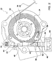
Fig. 2 is a cross sectional view illustrating the first locking mechanism of the reel assembly in the unlocked orientation. -
Fig. 3 is a cross sectional view of the first locking mechanism of the reel assembly in the locked orientation. -
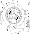
Fig. 4 is a cross sectional view of the second locking mechanism of the reel assembly in the unlocked orientation. -
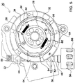
Fig. 5 is a cross sectional view of the second locking mechanism of the reel assembly in the locked orientation. -
Fig. 6 is a partially exploded view of the reel assembly showing both the first and second locking mechanisms. -
Fig. 7 is a perspective cut away view of the first locking mechanism assembly in the unlocked orientation. -
Fig. 8 is a perspective cut away view of the first locking mechanism in the locked orientation. - Similar reference characters refer to similar parts throughout the several views of the drawings.
PARTS LIST 20 Reel Assembly 44 Cut Out in Locking Bolt 22 Reel Housing 46 Housing for Locking Bolt 24 Webbing 48 Primary Locking Dog 26 Webbing Clasp 50 Locking Bolt Spring 28 Webbing Shaft 52 Sear 32 Geared End Plate of Webbing Shaft 54 Push Button 34 Locking Ring 56 Guard 36 Ramp on Locking Ring 58 Pawls 38 Trigger 62 Calibration Springs 40 Spring Housings 64 Recesses on Locking Ring 42 Locking Bolt 66 Accelerometer - The present invention relates to an improved reel assembly for use in conjunction with the occupant restraint system of a vehicle. The assembly employs a dual locking arrangement whereby an occupant can be restrained during both major and minor incidents. After a major incident, such as a collision, the reel assembly remains locked until the occupant disengages the reel by accessing a push button. After a minor incident, such as a fall, the reel assembly can be conveniently unlocked, without the need for accessing the push button, by applying counter tension to the restraint webbing. The details of the present invention are more fully described hereinafter.
- A specific implementation of the present invention is next described in conjunction with
Figures 1-8 . This implementation includes dual locking mechanisms for restraining a vehicle occupant by controlling the displacement of a length of webbing (24) during both major and minor incidents. As is conventional, the webbing (24) includes a webbing clasp (26) at its distal end that can be releasably secured to a harness or other restraint system. - The webbing (24) within the interior is wound about a webbing shaft (28) of the reel assembly (20). As illustrated in
Figure 2 , the shaft (28) includes a geared plate (32) at one end. A sufficient length of webbing (24) is included so as to permit the restrained occupant to travel throughout the vehicle. Rotation of the shaft (28) in a first sense results in the displacement of the webbing (24) and creation of sufficient slack so as to permit the free travel of the occupant within the vehicle. Likewise, rotation of the shaft (28) in the opposite sense results in slack being taken up so as to limit the movement of the occupant. As described in greater detail hereinafter, two distinct mechanisms are involved in preventing rotation of shaft (28). These mechanisms effectively restrain the occupant from any movement in the event the occupant falls (minor incident) or vehicle is involved in an accident(major incident). - As illustrated in
Figures 4 and5 , a pair of locking pawls (58) are pivotally secured to the geared end plate (32).Figure 4 illustrates the pawls (58) in the unpivoted orientation andFigure 5 illustrates the pawls (58) in the pivoted orientation. A calibration spring (62) is secured to each locking pawl (58) and serves to bias the pawl (58) into the unpivoted orientation. The bias of these spring can be overcome by centripetal acceleration whenever the webbing shaft (28) is rotated at a predetermined rate. When such forces are encountered, the pawls (58) are forced outwardly to the pivoted orientation whereby at least one of the pawls (58) engages a surrounding locking ring (34) (noteFigure 5 ) . - As illustrated, locking ring (34) includes a geared inner periphery that is adapted to be engaged by one of the pawls (58). The locking ring (34) also includes an outer surface with an associated ramp (36) (note
Figure 6 ). The function of this ramp is described in greater detail hereinafter. Locking ring (34) is positioned around the geared end plate (32) and is independently rotatable relative thereto. However, the locking ring (34) and the locking pawl (58) rotate together whenever one of the locking pawls (58) is engaged with the geared inner periphery of the locking ring (34). When this occurs, rotation of the webbing shaft (28) causes a corresponding rotation of the locking ring (34). Spring compartments (40) and internal springs are included to resist the rotation of the locking ring (34). - The operation of the locking bolt (42) is described next in association with
Figures 7 and8 . Locking bolt (42) ,which includes an elongated cutout (44) along its length, is positioned adjacent the webbing shaft (28). Locking bolt (42) has both an engaged and a disengaged position. A spring (50) is used to bias the locking bolt (42) into the engaged position. With continuing reference toFigures 7 and8 , trigger (38) and a sear (52) are operatively coupled to the locking bolt (42) and operate to keep the locking bolt (42) in either its disengaged or its engaged orientation. More specifically, sear (52) engages the lower extent of locking bolt (42) and maintains it in the disengaged position against the bias of the spring (50). - With reference to
Figure 6 , it can be seen that trigger (38) is adapted to engage the ramp (36) on the outer surface of the locking ring (34) during the extended rotation of locking ring (34). Namely, trigger (38) engages ramp (36) whenever locking ring (34) is rotated more than 45°. When this occurs, both trigger (38) and sear (52) are pivoted such that sear (52) temporarily disengages the locking bolt (42). This displacement of sear (52) permits spring (50) to force locking bolt (42) into the engaged position. This movement of the locking bolt (42), in turn, permits a locking dog (48) to engage geared end plate (32) so as to prohibit further displacement of webbing (24). - The locking dog (48) is pivotally secured adjacent the geared end plate (32) and has a distal end that rides within the elongated cut out (44) of the locking bolt (42). As noted in
Figure 7 , the elongated cut out (44) prevents the locking dog (48) from engaging the geared end plate (32) when the locking bolt (42) is in the disengaged position. However, when the locking bolt (42) is in the engaged position, the geometry of the elongated cut out (44) allows the locking dog (48) to engage the geared end plate (32), as depicted inFigure 8 . With the locking dog (48) so engaged, the webbing (24) is prevented from being displaced from the webbing shaft (28) and the occupant is effectively restrained. - In operation, rotation of the webbing shaft (28) at a predetermined rate causes the locking pawls (58) to move into the pivoted orientation and engage the locking ring (34). This restricts the displacement of the webbing (24) from the webbing shaft (28) and restrains the occupant. This level of restraint is triggered during minor incidents, such as when the occupant trips or falls. Locking pawls (58) remain engaged within locking ring (34) as long as tension remains in the webbing. The locking pawls (58) can be disengaged by applying a counter tension to the webbing (24) to reset the assembly.
- During major incidents, such a vehicle accident, the force on the webbing (24) will cause the locking pawls (58) to engage locking ring (34) and will further cause the locking ring (34) to rotate 45° or more. This rotation, in turn, causes trigger (38) to engage ramp (36), whereby sear (52) will be displaced. As noted in
Figure 8 , spring (50) will thereafter be permitted to move the locking bolt (42) into the engaged position such that the locking dog (48) engages the geared end plate (32). With the locking dog (48) fully engaged, further displacement of the webbing (24) is prevented and the occupant is fully restrained. Thus, during major incidents, an occupant is fully restrained. The user can thereafter release the locking dog (48) via a push button at the end of locking bolt (42). In addition to the foregoing, trigger (38) can also be tripped by a separate accelerometer (64). This accelerometer (64) provides a separate and independent means of triggering locking dog (48) and preventing the rotation of webbing shaft (28) during major incidents.
Claims (1)
- A reel assembly (20) with dual locking mechanisms for restraining a vehicle occupant by controlling the displacement of a length of webbing (24), the reel assembly (20) comprising:a webbing shaft (28) with a geared end plate (32), the webbing (24) being wound about the webbing shaft (28), the end of the webbing (24) being releasably secured to the occupant by way of a clasp (26), whereby displacement of the webbing (24) is controlled by rotation of the webbing shaft (28);a pair of locking pawls (58) pivotally secured to the geared end plate (32), each locking pawl (58) having pivoted and unpivoted orientations, a calibration spring (62) secured to each locking pawl (58), each of the calibration springs (62) having a bias that functions to urge the pawls (58) into the unpivoted orientation, the bias being overcome when the webbing shaft (28) is rotated at a predetermined rate, whereby the pawls (58) are moved to the pivoted orientation;a locking ring (34) having a geared inner periphery and an outer surface with a ramp (36), the locking ring (34) positioned around the geared end plate (32) and being independently rotatable thereto, at least one locking pawl (58) engaging the geared inner periphery of the locking ring (34) when the pawls (58) are in the pivoted orientation, whereby rotation of the webbing shaft (28) causes the rotation of the locking ring (34);a locking bolt (42) with an elongated cutout (44), the locking bolt (42) positioned adjacent the webbing shaft (28) and having engaged and disengaged positions, a spring (50) biasing the locking bolt (42) into the engaged position, a trigger (38) and a sear (52) operatively coupled to the locking bolt (42), with the sear (52) maintaining the locking bolt (42) in the disengaged position against the bias of the spring (50), the trigger (38) adapted to engage the ramp (36) on the outer surface of the locking ring (34) whereby the sear (52) is displaced so as to permit the locking bolt (42) to move into the engaged position;characterised in that a locking dog (48) that is pivotally secured adjacent the geared end plate (32) and having a distal end that rides within the elongated cut out (44) of the locking bolt (42), the elongated cut out (44) preventing the locking dog (48) from engaging the geared end plate (32) when the locking bolt (42) is in the disengaged position, the elongated cut out (44) forcing the locking dog (48) into engagement with the geared end plate (32) when the locking bolt (42) is in the engaged position, with the locking bolt (42) in engagement with the geared end plate (32) the webbing (24) is prevented from being displaced from the webbing shaft (28);whereby rotation of the webbing shaft (28) at a predetermined rate causes the locking pawls (58) to move into the pivoted orientation and engage the locking ring (34) to restrict the displacement of the webbing (24) from the webbing shaft (28), and wherein continued displacement of the webbing (24) causes the further rotation of the locking ring (34) which, in turn, causes trigger (38) to engage ramp (36), whereby sear (52) is displaced and spring (50) is permitted to move the locking bolt (42) into the engaged position such that the locking dog (48) engages the geared end plate (32) to prevent further displacement of the webbing (24).
Priority Applications (2)
| Application Number | Priority Date | Filing Date | Title |
|---|---|---|---|
| EP15195923.6A EP3002047B1 (en) | 2008-01-29 | 2009-01-29 | Reel lock for passenger restraint having dual locking positions |
| EP15195922.8A EP3002046B1 (en) | 2008-01-29 | 2009-01-29 | Reel lock for passenger restraint having dual locking positions |
Applications Claiming Priority (2)
| Application Number | Priority Date | Filing Date | Title |
|---|---|---|---|
| US2440908P | 2008-01-29 | 2008-01-29 | |
| PCT/US2009/032318 WO2009097376A1 (en) | 2008-01-29 | 2009-01-29 | Reel lock for passenger restraint having dual locking positions |
Related Child Applications (4)
| Application Number | Title | Priority Date | Filing Date |
|---|---|---|---|
| EP15195922.8A Division EP3002046B1 (en) | 2008-01-29 | 2009-01-29 | Reel lock for passenger restraint having dual locking positions |
| EP15195922.8A Division-Into EP3002046B1 (en) | 2008-01-29 | 2009-01-29 | Reel lock for passenger restraint having dual locking positions |
| EP15195923.6A Division EP3002047B1 (en) | 2008-01-29 | 2009-01-29 | Reel lock for passenger restraint having dual locking positions |
| EP15195923.6A Division-Into EP3002047B1 (en) | 2008-01-29 | 2009-01-29 | Reel lock for passenger restraint having dual locking positions |
Publications (3)
| Publication Number | Publication Date |
|---|---|
| EP2242543A1 EP2242543A1 (en) | 2010-10-27 |
| EP2242543A4 EP2242543A4 (en) | 2016-01-20 |
| EP2242543B1 true EP2242543B1 (en) | 2017-07-26 |
Family
ID=40913215
Family Applications (3)
| Application Number | Title | Priority Date | Filing Date |
|---|---|---|---|
| EP09705749.1A Active EP2242543B1 (en) | 2008-01-29 | 2009-01-29 | Reel lock for passenger restraint having dual locking positions |
| EP15195923.6A Active EP3002047B1 (en) | 2008-01-29 | 2009-01-29 | Reel lock for passenger restraint having dual locking positions |
| EP15195922.8A Active EP3002046B1 (en) | 2008-01-29 | 2009-01-29 | Reel lock for passenger restraint having dual locking positions |
Family Applications After (2)
| Application Number | Title | Priority Date | Filing Date |
|---|---|---|---|
| EP15195923.6A Active EP3002047B1 (en) | 2008-01-29 | 2009-01-29 | Reel lock for passenger restraint having dual locking positions |
| EP15195922.8A Active EP3002046B1 (en) | 2008-01-29 | 2009-01-29 | Reel lock for passenger restraint having dual locking positions |
Country Status (3)
| Country | Link |
|---|---|
| US (2) | US8251304B2 (en) |
| EP (3) | EP2242543B1 (en) |
| WO (1) | WO2009097376A1 (en) |
Families Citing this family (18)
| Publication number | Priority date | Publication date | Assignee | Title |
|---|---|---|---|---|
| EP2600941A4 (en) | 2010-08-02 | 2016-07-20 | Carleton Life Support Sys Inc | Restraint and extraction harness with associated release mechanism |
| US8516979B2 (en) * | 2010-09-27 | 2013-08-27 | Joseph Ek | Retractable leash with automatic braking mechanism |
| US8662436B2 (en) * | 2010-12-23 | 2014-03-04 | Carleton Life Support Systems Inc. | Apparatus for adjusting the payout of tether from a reel assembly |
| US8612099B2 (en) * | 2011-05-06 | 2013-12-17 | Tk Holdings Inc. | Occupant restraint system |
| US9144719B1 (en) * | 2014-06-18 | 2015-09-29 | Wilson Sporting Goods Co. | Golf club adjustable hosel assembly |
| US9144720B1 (en) * | 2014-06-18 | 2015-09-29 | Wilson Sporting Goods Co. | Golf club adjustable hosel assembly |
| US9358429B2 (en) * | 2014-06-18 | 2016-06-07 | Wilson Sporting Goods Co. | Golf club adjustable hosel assembly |
| US9517841B2 (en) | 2015-04-01 | 2016-12-13 | Carleton Life Support Systems, Inc. | Ballistic powered inertia reel |
| DE102015109444B4 (en) * | 2015-06-12 | 2018-08-02 | Bornack Gmbh & Co. Kg | Rope securing device |
| US9751495B2 (en) * | 2015-08-21 | 2017-09-05 | Carleton Life Support Systems, Inc. | Reel lock having multiple tooth dog |
| FR3042718B1 (en) * | 2015-10-26 | 2017-12-01 | Vertic | AUTOMATICALLY RECALLING FALL ARREST |
| BR122021013798B1 (en) | 2015-12-18 | 2023-04-18 | Eddy Current Limited Partnership | VARIABLE OPERATING CONTROL MECHANISM FOR MOTOR SYSTEM |
| USD929074S1 (en) * | 2018-04-05 | 2021-08-31 | Braunability Uk Limited | Safety belt |
| TWI668031B (en) * | 2018-09-11 | 2019-08-11 | 振鋒企業股份有限公司 | Fall arrester |
| US11833994B1 (en) | 2021-11-29 | 2023-12-05 | Clinton A. Sadler | Pet safety restraint device for vehicles |
| US12538899B1 (en) | 2021-11-29 | 2026-02-03 | Clinton A. Sadler | Pet safety restraint device for vehicles |
| US20230242063A1 (en) * | 2022-02-02 | 2023-08-03 | Nick Smart | Automotive restraining belt and protective device therefor |
| CN116692245B (en) * | 2023-07-18 | 2025-12-26 | 泰州润杰物流安全装备科技有限公司 | An inertial centrifugal force controlled safety belt tensioning device |
Family Cites Families (23)
| Publication number | Priority date | Publication date | Assignee | Title |
|---|---|---|---|---|
| US2791397A (en) * | 1954-11-24 | 1957-05-07 | Inland Steel Co | Safety reel |
| US3240510A (en) * | 1962-06-13 | 1966-03-15 | Pacific Scientific Co | Safety harness |
| US4083511A (en) | 1975-04-03 | 1978-04-11 | Nsk-Warner K. K. | Seat belt retractor |
| AU521860B2 (en) * | 1978-05-03 | 1982-05-06 | Martin Lindblad Stig | Locking device for reel belt type safety belts |
| JPS5740456U (en) | 1980-08-19 | 1982-03-04 | ||
| US4381086A (en) * | 1980-09-25 | 1983-04-26 | Allied Corporation | Seat belt retractor structure |
| DE3043014C2 (en) * | 1980-11-14 | 1987-03-19 | TRW Repa GmbH, 7077 Alfdorf | Automatic retractor for a safety belt in motor vehicles |
| US4396167A (en) * | 1981-04-08 | 1983-08-02 | General Motors Corporation | Lock bar and belt clamp release for seat belt retractor |
| US4386745A (en) * | 1981-08-10 | 1983-06-07 | General Motors Corporation | Tension reliever for seat belt retractor |
| US4925124A (en) * | 1987-04-03 | 1990-05-15 | Pacific Scientific Company | Dual-mode inertia reel system |
| US4801105A (en) | 1987-10-01 | 1989-01-31 | Pzf, Inc. | Shoulder harness reel assembly with automatic reel lock |
| US4955556A (en) | 1987-10-01 | 1990-09-11 | Pzf, Inc. | Shoulder harness reel assembly with automatic reel lock |
| US4917325A (en) * | 1987-12-23 | 1990-04-17 | Allied-Signal Inc. | Webbing sensor |
| JPH0785979B2 (en) | 1989-09-11 | 1995-09-20 | タカタ株式会社 | Seat belt retractor |
| GB9027783D0 (en) * | 1990-12-21 | 1991-02-13 | Barrow Hepburn Sala Ltd | Safety anchorages for controlling pay-out of a safety line |
| DE4314883A1 (en) * | 1993-05-05 | 1994-11-10 | Trw Repa Gmbh | Seat belt retractor |
| DE4345457C2 (en) * | 1993-09-13 | 2002-07-04 | Autoliv Dev | Belt retractor-belt tensioner combination with force limiter |
| DE4333760A1 (en) * | 1993-10-04 | 1995-04-06 | Trw Repa Gmbh | Belt retractor for restraint systems in vehicles |
| US5636807A (en) | 1994-08-01 | 1997-06-10 | H. Koch & Sons Co., Inc. | Acceleration sensor having inertia weight responsive to accelerations in every direction |
| US6068208A (en) | 1995-03-16 | 2000-05-30 | Nsk Ltd. | Retractor for use with a seat belt |
| US5771993A (en) * | 1996-06-14 | 1998-06-30 | Dalloz Safety, Inc. | Safety devices for fall restraint |
| US20060237573A1 (en) * | 2005-04-22 | 2006-10-26 | Key Safety Systems, Inc. | Seat belt retractor with improved web sensor |
| US7275710B2 (en) | 2005-06-15 | 2007-10-02 | Vandruff Charles E | Aircrew restraint system |
-
2009
- 2009-01-29 EP EP09705749.1A patent/EP2242543B1/en active Active
- 2009-01-29 EP EP15195923.6A patent/EP3002047B1/en active Active
- 2009-01-29 WO PCT/US2009/032318 patent/WO2009097376A1/en not_active Ceased
- 2009-01-29 EP EP15195922.8A patent/EP3002046B1/en active Active
- 2009-01-29 US US12/361,581 patent/US8251304B2/en active Active
-
2012
- 2012-08-27 US US13/595,354 patent/US9573564B2/en active Active
Non-Patent Citations (1)
| Title |
|---|
| None * |
Also Published As
| Publication number | Publication date |
|---|---|
| EP3002047A1 (en) | 2016-04-06 |
| US20090321550A1 (en) | 2009-12-31 |
| EP2242543A4 (en) | 2016-01-20 |
| US20130134251A1 (en) | 2013-05-30 |
| EP3002046B1 (en) | 2017-08-16 |
| EP3002047B1 (en) | 2017-04-26 |
| EP2242543A1 (en) | 2010-10-27 |
| US9573564B2 (en) | 2017-02-21 |
| EP3002046A1 (en) | 2016-04-06 |
| US8251304B2 (en) | 2012-08-28 |
| WO2009097376A1 (en) | 2009-08-06 |
Similar Documents
| Publication | Publication Date | Title |
|---|---|---|
| EP3002047B1 (en) | Reel lock for passenger restraint having dual locking positions | |
| EP3337696B1 (en) | Reel lock having multiple tooth dog | |
| EP1062122B1 (en) | Energy management safety belt retractor | |
| US5934596A (en) | Automatic locking retractor with timing clutch mechanism | |
| US20090069983A1 (en) | Occupant restraint systems for use in military land vehicles and other vehicles | |
| CN111542457B (en) | Seat belt retractor with energy absorbing mechanism | |
| JP2009061809A (en) | Seat belt retractor and seat belt device using the same | |
| EP1728693B1 (en) | Automatic locking retractor | |
| DE112017006681T5 (en) | Child seat recognition with airbag or belt tensioner suppression | |
| US20090212159A1 (en) | Restraint System | |
| JPH037234Y2 (en) | ||
| US20070090224A1 (en) | Apparatus and method to reduce/eliminate lockup of seatbelt retractor during motorized pretensioning activation | |
| EP3297868B1 (en) | Ballistic powered inertia reel | |
| US4568037A (en) | Webbing tension device | |
| US4546934A (en) | Webbing tension device | |
| US4585184A (en) | Webbing tension device | |
| GB2110070A (en) | Emergency locking device for safety belt retractor | |
| JPH11192923A (en) | Seat belt retractor | |
| JPH05131893A (en) | Webbing winding device | |
| JPS5915655Y2 (en) | Retractor lock release device with emergency lock mechanism | |
| JPH0245095Y2 (en) | ||
| JP6498070B2 (en) | Webbing take-up device | |
| JPH10175504A (en) | Occupant restraint |
Legal Events
| Date | Code | Title | Description |
|---|---|---|---|
| PUAI | Public reference made under article 153(3) epc to a published international application that has entered the european phase |
Free format text: ORIGINAL CODE: 0009012 |
|
| 17P | Request for examination filed |
Effective date: 20100827 |
|
| AK | Designated contracting states |
Kind code of ref document: A1 Designated state(s): AT BE BG CH CY CZ DE DK EE ES FI FR GB GR HR HU IE IS IT LI LT LU LV MC MK MT NL NO PL PT RO SE SI SK TR |
|
| AX | Request for extension of the european patent |
Extension state: AL BA RS |
|
| RAP1 | Party data changed (applicant data changed or rights of an application transferred) |
Owner name: CARLETON LIFE SUPPORT SYSTEMS INC. |
|
| RA4 | Supplementary search report drawn up and despatched (corrected) |
Effective date: 20151217 |
|
| RIC1 | Information provided on ipc code assigned before grant |
Ipc: A62B 35/00 20060101AFI20151211BHEP |
|
| RIC1 | Information provided on ipc code assigned before grant |
Ipc: A62B 35/00 20060101AFI20151223BHEP |
|
| RIN1 | Information on inventor provided before grant (corrected) |
Inventor name: MEGGS, DANIEL Inventor name: LANE, ALAN Inventor name: BOYER, JOHN |
|
| GRAP | Despatch of communication of intention to grant a patent |
Free format text: ORIGINAL CODE: EPIDOSNIGR1 |
|
| INTG | Intention to grant announced |
Effective date: 20170314 |
|
| GRAS | Grant fee paid |
Free format text: ORIGINAL CODE: EPIDOSNIGR3 |
|
| GRAA | (expected) grant |
Free format text: ORIGINAL CODE: 0009210 |
|
| AK | Designated contracting states |
Kind code of ref document: B1 Designated state(s): AT BE BG CH CY CZ DE DK EE ES FI FR GB GR HR HU IE IS IT LI LT LU LV MC MK MT NL NO PL PT RO SE SI SK TR |
|
| AX | Request for extension of the european patent |
Extension state: AL BA RS |
|
| REG | Reference to a national code |
Ref country code: GB Ref legal event code: FG4D |
|
| REG | Reference to a national code |
Ref country code: CH Ref legal event code: EP |
|
| REG | Reference to a national code |
Ref country code: AT Ref legal event code: REF Ref document number: 911913 Country of ref document: AT Kind code of ref document: T Effective date: 20170815 |
|
| REG | Reference to a national code |
Ref country code: IE Ref legal event code: FG4D |
|
| REG | Reference to a national code |
Ref country code: DE Ref legal event code: R096 Ref document number: 602009047333 Country of ref document: DE |
|
| REG | Reference to a national code |
Ref country code: NL Ref legal event code: MP Effective date: 20170726 |
|
| REG | Reference to a national code |
Ref country code: LT Ref legal event code: MG4D |
|
| REG | Reference to a national code |
Ref country code: AT Ref legal event code: MK05 Ref document number: 911913 Country of ref document: AT Kind code of ref document: T Effective date: 20170726 |
|
| PG25 | Lapsed in a contracting state [announced via postgrant information from national office to epo] |
Ref country code: LT Free format text: LAPSE BECAUSE OF FAILURE TO SUBMIT A TRANSLATION OF THE DESCRIPTION OR TO PAY THE FEE WITHIN THE PRESCRIBED TIME-LIMIT Effective date: 20170726 Ref country code: HR Free format text: LAPSE BECAUSE OF FAILURE TO SUBMIT A TRANSLATION OF THE DESCRIPTION OR TO PAY THE FEE WITHIN THE PRESCRIBED TIME-LIMIT Effective date: 20170726 Ref country code: NL Free format text: LAPSE BECAUSE OF FAILURE TO SUBMIT A TRANSLATION OF THE DESCRIPTION OR TO PAY THE FEE WITHIN THE PRESCRIBED TIME-LIMIT Effective date: 20170726 Ref country code: FI Free format text: LAPSE BECAUSE OF FAILURE TO SUBMIT A TRANSLATION OF THE DESCRIPTION OR TO PAY THE FEE WITHIN THE PRESCRIBED TIME-LIMIT Effective date: 20170726 Ref country code: AT Free format text: LAPSE BECAUSE OF FAILURE TO SUBMIT A TRANSLATION OF THE DESCRIPTION OR TO PAY THE FEE WITHIN THE PRESCRIBED TIME-LIMIT Effective date: 20170726 Ref country code: NO Free format text: LAPSE BECAUSE OF FAILURE TO SUBMIT A TRANSLATION OF THE DESCRIPTION OR TO PAY THE FEE WITHIN THE PRESCRIBED TIME-LIMIT Effective date: 20171026 Ref country code: SE Free format text: LAPSE BECAUSE OF FAILURE TO SUBMIT A TRANSLATION OF THE DESCRIPTION OR TO PAY THE FEE WITHIN THE PRESCRIBED TIME-LIMIT Effective date: 20170726 |
|
| PG25 | Lapsed in a contracting state [announced via postgrant information from national office to epo] |
Ref country code: PL Free format text: LAPSE BECAUSE OF FAILURE TO SUBMIT A TRANSLATION OF THE DESCRIPTION OR TO PAY THE FEE WITHIN THE PRESCRIBED TIME-LIMIT Effective date: 20170726 Ref country code: ES Free format text: LAPSE BECAUSE OF FAILURE TO SUBMIT A TRANSLATION OF THE DESCRIPTION OR TO PAY THE FEE WITHIN THE PRESCRIBED TIME-LIMIT Effective date: 20170726 Ref country code: GR Free format text: LAPSE BECAUSE OF FAILURE TO SUBMIT A TRANSLATION OF THE DESCRIPTION OR TO PAY THE FEE WITHIN THE PRESCRIBED TIME-LIMIT Effective date: 20171027 Ref country code: IS Free format text: LAPSE BECAUSE OF FAILURE TO SUBMIT A TRANSLATION OF THE DESCRIPTION OR TO PAY THE FEE WITHIN THE PRESCRIBED TIME-LIMIT Effective date: 20171126 Ref country code: LV Free format text: LAPSE BECAUSE OF FAILURE TO SUBMIT A TRANSLATION OF THE DESCRIPTION OR TO PAY THE FEE WITHIN THE PRESCRIBED TIME-LIMIT Effective date: 20170726 Ref country code: BG Free format text: LAPSE BECAUSE OF FAILURE TO SUBMIT A TRANSLATION OF THE DESCRIPTION OR TO PAY THE FEE WITHIN THE PRESCRIBED TIME-LIMIT Effective date: 20171026 |
|
| PG25 | Lapsed in a contracting state [announced via postgrant information from national office to epo] |
Ref country code: CZ Free format text: LAPSE BECAUSE OF FAILURE TO SUBMIT A TRANSLATION OF THE DESCRIPTION OR TO PAY THE FEE WITHIN THE PRESCRIBED TIME-LIMIT Effective date: 20170726 Ref country code: DK Free format text: LAPSE BECAUSE OF FAILURE TO SUBMIT A TRANSLATION OF THE DESCRIPTION OR TO PAY THE FEE WITHIN THE PRESCRIBED TIME-LIMIT Effective date: 20170726 Ref country code: RO Free format text: LAPSE BECAUSE OF FAILURE TO SUBMIT A TRANSLATION OF THE DESCRIPTION OR TO PAY THE FEE WITHIN THE PRESCRIBED TIME-LIMIT Effective date: 20170726 |
|
| REG | Reference to a national code |
Ref country code: DE Ref legal event code: R097 Ref document number: 602009047333 Country of ref document: DE |
|
| PG25 | Lapsed in a contracting state [announced via postgrant information from national office to epo] |
Ref country code: EE Free format text: LAPSE BECAUSE OF FAILURE TO SUBMIT A TRANSLATION OF THE DESCRIPTION OR TO PAY THE FEE WITHIN THE PRESCRIBED TIME-LIMIT Effective date: 20170726 Ref country code: SK Free format text: LAPSE BECAUSE OF FAILURE TO SUBMIT A TRANSLATION OF THE DESCRIPTION OR TO PAY THE FEE WITHIN THE PRESCRIBED TIME-LIMIT Effective date: 20170726 Ref country code: IT Free format text: LAPSE BECAUSE OF FAILURE TO SUBMIT A TRANSLATION OF THE DESCRIPTION OR TO PAY THE FEE WITHIN THE PRESCRIBED TIME-LIMIT Effective date: 20170726 |
|
| PLBE | No opposition filed within time limit |
Free format text: ORIGINAL CODE: 0009261 |
|
| STAA | Information on the status of an ep patent application or granted ep patent |
Free format text: STATUS: NO OPPOSITION FILED WITHIN TIME LIMIT |
|
| 26N | No opposition filed |
Effective date: 20180430 |
|
| PG25 | Lapsed in a contracting state [announced via postgrant information from national office to epo] |
Ref country code: SI Free format text: LAPSE BECAUSE OF FAILURE TO SUBMIT A TRANSLATION OF THE DESCRIPTION OR TO PAY THE FEE WITHIN THE PRESCRIBED TIME-LIMIT Effective date: 20170726 |
|
| REG | Reference to a national code |
Ref country code: CH Ref legal event code: PL |
|
| GBPC | Gb: european patent ceased through non-payment of renewal fee |
Effective date: 20180129 |
|
| PG25 | Lapsed in a contracting state [announced via postgrant information from national office to epo] |
Ref country code: FR Free format text: LAPSE BECAUSE OF NON-PAYMENT OF DUE FEES Effective date: 20180131 Ref country code: LU Free format text: LAPSE BECAUSE OF NON-PAYMENT OF DUE FEES Effective date: 20180129 |
|
| REG | Reference to a national code |
Ref country code: IE Ref legal event code: MM4A |
|
| REG | Reference to a national code |
Ref country code: FR Ref legal event code: ST Effective date: 20180928 |
|
| REG | Reference to a national code |
Ref country code: BE Ref legal event code: MM Effective date: 20180131 |
|
| PG25 | Lapsed in a contracting state [announced via postgrant information from national office to epo] |
Ref country code: LI Free format text: LAPSE BECAUSE OF NON-PAYMENT OF DUE FEES Effective date: 20180131 Ref country code: GB Free format text: LAPSE BECAUSE OF NON-PAYMENT OF DUE FEES Effective date: 20180129 Ref country code: BE Free format text: LAPSE BECAUSE OF NON-PAYMENT OF DUE FEES Effective date: 20180131 Ref country code: CH Free format text: LAPSE BECAUSE OF NON-PAYMENT OF DUE FEES Effective date: 20180131 |
|
| PG25 | Lapsed in a contracting state [announced via postgrant information from national office to epo] |
Ref country code: IE Free format text: LAPSE BECAUSE OF NON-PAYMENT OF DUE FEES Effective date: 20180129 |
|
| PG25 | Lapsed in a contracting state [announced via postgrant information from national office to epo] |
Ref country code: MC Free format text: LAPSE BECAUSE OF FAILURE TO SUBMIT A TRANSLATION OF THE DESCRIPTION OR TO PAY THE FEE WITHIN THE PRESCRIBED TIME-LIMIT Effective date: 20170726 |
|
| REG | Reference to a national code |
Ref country code: DE Ref legal event code: R082 Ref document number: 602009047333 Country of ref document: DE Representative=s name: MURGITROYD GERMANY PATENTANWALTSGESELLSCHAFT M, DE Ref country code: DE Ref legal event code: R082 Ref document number: 602009047333 Country of ref document: DE Representative=s name: MURGITROYD & COMPANY, DE Ref country code: DE Ref legal event code: R081 Ref document number: 602009047333 Country of ref document: DE Owner name: COBHAM MISSION SYSTEMS DAVENPORT LSS INC., DAV, US Free format text: FORMER OWNER: CARLETON LIFE SUPPORT SYSTEMS, INC., DAVENPORT, IA., US |
|
| PG25 | Lapsed in a contracting state [announced via postgrant information from national office to epo] |
Ref country code: MT Free format text: LAPSE BECAUSE OF NON-PAYMENT OF DUE FEES Effective date: 20180129 |
|
| PG25 | Lapsed in a contracting state [announced via postgrant information from national office to epo] |
Ref country code: TR Free format text: LAPSE BECAUSE OF FAILURE TO SUBMIT A TRANSLATION OF THE DESCRIPTION OR TO PAY THE FEE WITHIN THE PRESCRIBED TIME-LIMIT Effective date: 20170726 |
|
| PG25 | Lapsed in a contracting state [announced via postgrant information from national office to epo] |
Ref country code: HU Free format text: LAPSE BECAUSE OF FAILURE TO SUBMIT A TRANSLATION OF THE DESCRIPTION OR TO PAY THE FEE WITHIN THE PRESCRIBED TIME-LIMIT; INVALID AB INITIO Effective date: 20090129 Ref country code: PT Free format text: LAPSE BECAUSE OF FAILURE TO SUBMIT A TRANSLATION OF THE DESCRIPTION OR TO PAY THE FEE WITHIN THE PRESCRIBED TIME-LIMIT Effective date: 20170726 |
|
| PG25 | Lapsed in a contracting state [announced via postgrant information from national office to epo] |
Ref country code: CY Free format text: LAPSE BECAUSE OF FAILURE TO SUBMIT A TRANSLATION OF THE DESCRIPTION OR TO PAY THE FEE WITHIN THE PRESCRIBED TIME-LIMIT Effective date: 20170726 Ref country code: MK Free format text: LAPSE BECAUSE OF NON-PAYMENT OF DUE FEES Effective date: 20170726 |
|
| PGFP | Annual fee paid to national office [announced via postgrant information from national office to epo] |
Ref country code: DE Payment date: 20251217 Year of fee payment: 18 |