EP2242237A1 - Portable electronic device - Google Patents
Portable electronic device Download PDFInfo
- Publication number
- EP2242237A1 EP2242237A1 EP10002527A EP10002527A EP2242237A1 EP 2242237 A1 EP2242237 A1 EP 2242237A1 EP 10002527 A EP10002527 A EP 10002527A EP 10002527 A EP10002527 A EP 10002527A EP 2242237 A1 EP2242237 A1 EP 2242237A1
- Authority
- EP
- European Patent Office
- Prior art keywords
- frame
- electronic device
- portable electronic
- relative
- position relative
- Prior art date
- Legal status (The legal status is an assumption and is not a legal conclusion. Google has not performed a legal analysis and makes no representation as to the accuracy of the status listed.)
- Granted
Links
Images


Classifications
-
- H—ELECTRICITY
- H04—ELECTRIC COMMUNICATION TECHNIQUE
- H04M—TELEPHONIC COMMUNICATION
- H04M1/00—Substation equipment, e.g. for use by subscribers
- H04M1/02—Constructional features of telephone sets
- H04M1/0202—Portable telephone sets, e.g. cordless phones, mobile phones or bar type handsets
- H04M1/0206—Portable telephones comprising a plurality of mechanically joined movable body parts, e.g. hinged housings
- H04M1/0208—Portable telephones comprising a plurality of mechanically joined movable body parts, e.g. hinged housings characterized by the relative motions of the body parts
- H04M1/0235—Slidable or telescopic telephones, i.e. with a relative translation movement of the body parts; Telephones using a combination of translation and other relative motions of the body parts
- H04M1/0237—Sliding mechanism with one degree of freedom
-
- H—ELECTRICITY
- H04—ELECTRIC COMMUNICATION TECHNIQUE
- H04M—TELEPHONIC COMMUNICATION
- H04M1/00—Substation equipment, e.g. for use by subscribers
- H04M1/02—Constructional features of telephone sets
- H04M1/0202—Portable telephone sets, e.g. cordless phones, mobile phones or bar type handsets
- H04M1/0206—Portable telephones comprising a plurality of mechanically joined movable body parts, e.g. hinged housings
- H04M1/0241—Portable telephones comprising a plurality of mechanically joined movable body parts, e.g. hinged housings using relative motion of the body parts to change the operational status of the telephone set, e.g. switching on/off, answering incoming call
-
- H—ELECTRICITY
- H04—ELECTRIC COMMUNICATION TECHNIQUE
- H04M—TELEPHONIC COMMUNICATION
- H04M1/00—Substation equipment, e.g. for use by subscribers
- H04M1/02—Constructional features of telephone sets
- H04M1/0202—Portable telephone sets, e.g. cordless phones, mobile phones or bar type handsets
- H04M1/0206—Portable telephones comprising a plurality of mechanically joined movable body parts, e.g. hinged housings
- H04M1/0208—Portable telephones comprising a plurality of mechanically joined movable body parts, e.g. hinged housings characterized by the relative motions of the body parts
- H04M1/0214—Foldable telephones, i.e. with body parts pivoting to an open position around an axis parallel to the plane they define in closed position
- H04M1/0216—Foldable in one direction, i.e. using a one degree of freedom hinge
Definitions
- the present application generally relates to a portable electronic device, in particular, to a portable electronic device capable of changing among various appearance states.
- the current portable electronic devices adopt a clam shell body design or a slide-type body design, in which a display screen and a keyboard are respectively located on two overlapped bodies, such that the user can conveniently operate the device.
- the current portable electronic device may also have a multimedia playing function, for example, watching movies, browsing pictures, and even holding video conferences.
- the two overlapped bodies are connected to each other in a pivoting manner, in which an inner surface of an upper body is provided with a screen, and an inner surface of a lower body facing the upper body is provided with a keyboard.
- a keyboard When the user intends to play audio/video products or enter a keyboard input mode, he/she may rotate the upper body relative to the lower body, and place the lower body of the portable electronic device on a platform, such that he/she may conveniently operate the device and enjoy the audio/video products.
- openings of a loudspeaker for certain portable electronic device are disposed on an outer surface of the lower body.
- the loudspeaker of the portable electronic device produces sound effects, the sound transmission is interfered since the openings are covered by the platform where the lower body is placed, and the sound output quality is deteriorated.
- the present application is directed to a portable electronic device, which is capable of changing among various appearance states.
- the present application provides a portable electronic device, which includes a first body, a second body, a first frame, a second frame, and a third frame.
- the first body has a first surface and a second surface opposite to each other.
- the second body is movably disposed on the first body and covers the first surface.
- the first frame is fixed on the first body.
- the second frame is pivoted to the first frame.
- the third frame is fixed on the second body and slidably coupled to the second frame.
- the second frame is capable of sliding between a first position and a second position relative to the third frame, such that the second body is capable of sliding relative to the first body.
- the first frame When the second frame is located on the second position relative to the third frame, the first frame is capable of rotating towards the first position from the second position to reach a third position relative to the second frame, such that the second body is capable of being turned over from the first surface to the second surface relative to the first body.
- the present application provides an operation method, applicable to operate the portable electronic device. Firstly, the second frame is located on the first position relative to the third frame, such that the portable electronic device enters a first operation mode. Next, the second frame is located on the second position relative to the third frame, such that the portable electronic device enters a second operation mode. Then, the first frame is located on the third position relative to the second frame, such that the portable electronic device enters a third operation mode.
- the second body is capable of being turned over from one surface of the first body to the other surface. Therefore, through the relative movements between the bodies, the portable electronic device is provided with additional appearance states.
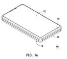
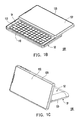
- FIGs. 1A to 1C are respectively perspective views of a portable electronic device in three appearance states according to an embodiment of the present invention.
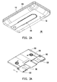
- FIGs. 2A to 2C are respectively perspective views of the portable electronic device of FIGs. 1A to 1C from another viewing angle.
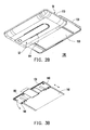
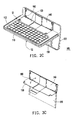
- FIGs. 3A to 3C are respectively perspective views of a plurality of components, including frames and other components, of the portable electronic device of FIGs. 2A to 2C .
- FIG. 4 is a bottom view of the frames and other components of FIG. 3A .
- FIG. 5A is a partial front view of the frames and other components of FIG. 3A .
- FIG. 5B is a partial front view of the frames and other components of FIG. 3B .
- FIG. 6A is a front view of the frames and other components of FIG. 3C .
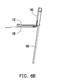
- FIG. 6B is a side view of the frames and other components of FIG. 6A .
- FIGs. 1A to 1C are respectively perspective views of a portable electronic device in three appearance states according to an embodiment of the present invention
- FIGs. 2A to 2C are respectively perspective views of the portable electronic device of FIGs. 1A to 1C from another viewing angle
- FIGs. 3A to 3C are respectively perspective views of a plurality of components, including frames and other components, of the portable electronic device of FIGs. 2A to 2C .
- a portable electronic device 100 includes a first body 110 and a second body 120.
- the first body 110 has a first surface S 1 and a second surface S2 opposite to each other.
- the second body 120 is located on the first body 110 and covers the first surface S1.
- the portable electronic device 100 further includes a first frame 130, a second frame 140, and a third frame 150.
- the first frame 130 is fixed on the first body 110 of FIG. 2C .
- the second frame 140 is pivoted to the first frame 130.
- the third frame 150 is fixed on the second body 120 of FIG. 2C .
- the third frame 150 is slidably coupled to the second frame 140, as shown in FIGs. 3A and 3B .
- the second frame 140 is capable of sliding between a first position of FIG. 3A and a second position of FIG. 3B relative to the third frame 150, such that the second body 120 is capable of sliding between the positions of FIGs. 2A and 2B relative to the first body 110.
- the first frame 130 is capable of rotating towards the first position of FIG. 3A from the second position of FIG. 3B to reach a third position of FIG. 3C relative to the second frame 140, such that the second body 120 is capable of being turned over from the first surface S 1 to the second surface S2 relative to the first body 110, as shown in FIG. 2C .
- the second body 120 is capable of being turned over from the first surface S 1 to the second surface S2 relative to the first body 110, such that the portable electronic device 100 is provided with an additional appearance state, so that the applications of the portable electronic device 100 are further expanded when being used together with the software.
- FIG. 4 is a bottom view of the frames and other components of FIG. 3A
- FIG. 5A is a partial front view of the frames and other components of FIG. 3A
- a first limiting part 160 is represented by slashes here.
- the portable electronic device 100 further includes a first limiting part 160, connected to the second frame 140.
- the first limiting part 160 includes a first elastic portion 162 and a first limiting portion 164.
- the first elastic portion 162 is fixed on the second frame 140.
- the first limiting portion 164 extends from the first elastic portion 162.
- the first frame 130 has a stopping portion 134. Therefore, when the second frame 140 slides relative to the third frame 150, the first limiting part 160 interferes with the stopping portion 134, so as to limit the rotation of the first frame 130 relative to the second frame 140.
- FIG. 5B is a partial front view of the frames and other components of FIG. 3B .
- the third frame 150 has a first restraining part 152, and when the second frame 140 slides to the second position of FIG. 3B relative to the third frame 150, the first restraining part 152 releases the limiting effect of the first limiting part 160 on the rotation of the first frame 130.
- the first restraining part 152 pushes the first elastic portion 162, so as to release the interference relationship between the first limiting portion 164 and the stopping portion 134.
- FIG. 6A is a front view of the frames and other components of FIG. 3C
- FIG. 6B is a side view of the frames and other components of FIG. 6A
- the portable electronic device 100 further includes a second limiting part 170, connected to the second frame 140.
- the second limiting part 170 includes a second elastic portion 172 and a second limiting portion 174.
- the second elastic portion 172 is fixed on the second frame 140.
- the second limiting portion 174 extends from the second elastic portion 172.
- the third frame 150 has a snapping portion 154, which is also shown in FIG. 4 . Therefore, when the first frame 130 rotates relative to the second frame 140, the second limiting portion 174 interferes with the snapping portion 154, so as to limit the rotation of the second frame 140 relative to the third frame 150.
- the first frame 130 has a second restraining part 132.
- the second restraining part 132 releases the limitation effect of the second limiting part 170 on the sliding motion of the third frame 150.
- the second restraining part 132 pushes the second elastic portion 172, so as to release the interference relationship between the second limiting portion 174 and the snapping portion 154.
- the first frame 130 and the second frame 140 are attached to each other under a magnetic attraction force, such that the user can conveniently control the rotation of the first frame 130 relative to the second frame 140.
- the portable electronic device 100 further includes a magnetic part 180 arranged on the first frame 130, and the second frame 140 correspondingly has magnetic susceptibility, such that the first frame 130 is capable of being attached on the second frame 140.
- two magnetic parts are respectively arranged on the first frame 130 and the second frame 140, and the first frame 130 and the second frame 140 are attached to each other under the magnetic attraction force between the two magnetic parts.
- the portable electronic device 100 further includes a first driving part 190 connected between the first frame 130 and the second frame 140.
- the first driving part 190 is, for example, a torsion spring.
- the first driving part 190 is compressed.
- the first limiting part 160 releases the limiting relationship with the first frame 130, such that the first driving part 190 drives the first frame 130 and the second frame 140 to rotate relative to each other.
- an elastic force of the first driving part 190 is insufficient for separating the first frame 130 from the second frame 140.
- the elastic force of the first driving part 190 enables the portable electronic device 100 to maintain the state of FIG. 1C .
- the first body 110 has a keyboard 112 and a loudspeaker opening 114.
- the keyboard 112 is, for example, a QWERTY keyboard, and is located on the first surface S1.
- the loudspeaker opening 114 is located on the second surface S2.
- the loudspeaker opening 114 is located on the second surface S2 of the first body 110, when the second body 120 is located on a position of FIG. 2C relative to the first body 110, the loudspeaker opening 114 is exposed out of the first body 110. In this way, the sounds produced by a loudspeaker (not shown) configured within the portable electronic device 100 are transmitted from the loudspeaker opening 114 without being interfered, thereby achieving a desirable sound quality.
- the portable electronic device 100 further includes at least one second driving part 200 connected between the second frame 140 and the third frame 150.
- the second driving part 200 is, for example, a torsion spring or any other device capable of providing an elastic force.
- the second driving part 200 provides a driving force on the second frame 140 and the third frame 150, such that the second body 120 and the first body 110 can slide with respect to each other in a semi-auto sliding manner.
- the present invention provides an operation method, applicable to operate the portable electronic device 100, in which the structure of the portable electronic device 100 has already been described in the above embodiments, so it is not described here repeatedly.
- the operation method enables the portable electronic device 100 to have three different appearance states as follows.
- the second frame 140 is located on the first position of FIG. 3A relative to the third frame 150, such that the relative position between the second body 120 and the first body 110 is as shown in FIG. 1A , and the portable electronic device 100 enters a first operation mode.
- the second body 120 has a screen 122, which may be a touch screen. Therefore, the user can manipulate the portable electronic device 100 through the screen 122 in the first operation mode.
- the first operation mode includes a phone mode.
- the second frame 140 is located on the second position relative to the third frame 150, such that the relative position between the second body 120 and the first body 110 is as shown in FIG. 1B , and the portable electronic device 100 enters a second operation mode, including an input mode.
- the keyboard 112 is exposed out of the first body 110, such that the user can conveniently manipulate the portable electronic device 100 through the screen 122 and the keyboard 112.
- the first frame 130 is located on the third position relative to the second frame 140, such that the relative position between the second body 120 and the first body 110 is as shown in FIG. 1C , and the portable electronic device 100 enters a third operation mode, including a multimedia playing mode.
- the loudspeaker opening 114 (as shown in FIGs. 2A and 2B ) of the portable electronic device 100 is located on the second surface S2, such that the portable electronic device 100 can provide a high sound output quality when playing audio/video products.
- the angle of the screen 122 is also suitable for being viewed by the user, such that the third operation mode is suitable for playing audio/video products or holding video conferences.
- the second body is capable of sliding relative to the first body through the frames, and is capable of being turned over from the first surface of the first body to the second surface thereof relative to the first body. Therefore, as compared with the prior art, the portable electronic device in the above embodiments is further provided with an additional appearance state, so that the operation scope of the portable electronic device is further expanded when being used together with the software.
- the loudspeaker opening of the second body is located on the second surface, when the second body is turned over relative to the first body, and the portable electronic device enters the third operation mode (for example, multimedia playing mode), and is placed on the platform, the loudspeaker opening is exposed out of the second body and is not covered by the platform, such that the high sound output quality is maintained, and thus the third operation mode is suitable for playing audio/video products.
- the third operation mode for example, multimedia playing mode
Landscapes
- Engineering & Computer Science (AREA)
- Signal Processing (AREA)
- Telephone Set Structure (AREA)
- Casings For Electric Apparatus (AREA)
Abstract
Description
- The present application generally relates to a portable electronic device, in particular, to a portable electronic device capable of changing among various appearance states.
- With the rapid progress of technologies, electronic devices have become increasingly indispensable in people's daily life. Nowadays, users' requirements on electronic devices generally include a high operation performance, and features of being light, thin, short, and small, and so on. Therefore, various portable electronic devices, including an ultra mobile personal computer (UMPC), a tablet personal computer (tablet PC), a pocket PC, a personal digital assistance (PDA), a cell phone, and a notebook PC have been gradually proposed.
- Most of the current portable electronic devices adopt a clam shell body design or a slide-type body design, in which a display screen and a keyboard are respectively located on two overlapped bodies, such that the user can conveniently operate the device. In addition to basic modes of, for example, inputting via the keyboard and wireless communication, the current portable electronic device may also have a multimedia playing function, for example, watching movies, browsing pictures, and even holding video conferences.
- In a clam shell portable electronic device, the two overlapped bodies are connected to each other in a pivoting manner, in which an inner surface of an upper body is provided with a screen, and an inner surface of a lower body facing the upper body is provided with a keyboard. When the user intends to play audio/video products or enter a keyboard input mode, he/she may rotate the upper body relative to the lower body, and place the lower body of the portable electronic device on a platform, such that he/she may conveniently operate the device and enjoy the audio/video products.
- However, openings of a loudspeaker for certain portable electronic device are disposed on an outer surface of the lower body. As a result, when the loudspeaker of the portable electronic device produces sound effects, the sound transmission is interfered since the openings are covered by the platform where the lower body is placed, and the sound output quality is deteriorated.
- Accordingly, the present application is directed to a portable electronic device, which is capable of changing among various appearance states.
- The present application provides a portable electronic device, which includes a first body, a second body, a first frame, a second frame, and a third frame. The first body has a first surface and a second surface opposite to each other. The second body is movably disposed on the first body and covers the first surface. The first frame is fixed on the first body. The second frame is pivoted to the first frame. The third frame is fixed on the second body and slidably coupled to the second frame. The second frame is capable of sliding between a first position and a second position relative to the third frame, such that the second body is capable of sliding relative to the first body. When the second frame is located on the second position relative to the third frame, the first frame is capable of rotating towards the first position from the second position to reach a third position relative to the second frame, such that the second body is capable of being turned over from the first surface to the second surface relative to the first body.
- The present application provides an operation method, applicable to operate the portable electronic device. Firstly, the second frame is located on the first position relative to the third frame, such that the portable electronic device enters a first operation mode. Next, the second frame is located on the second position relative to the third frame, such that the portable electronic device enters a second operation mode. Then, the first frame is located on the third position relative to the second frame, such that the portable electronic device enters a third operation mode.
- Based on the above mentioned, in the present application, besides sliding relative to the first body, the second body is capable of being turned over from one surface of the first body to the other surface. Therefore, through the relative movements between the bodies, the portable electronic device is provided with additional appearance states.
- The accompanying drawings are included to provide a further understanding of the invention, and are incorporated in and constitute a part of this specification. The drawings illustrate embodiments of the invention and, together with the description, serve to explain the principles of the invention.
-
FIGs. 1A to 1C are respectively perspective views of a portable electronic device in three appearance states according to an embodiment of the present invention. -
FIGs. 2A to 2C are respectively perspective views of the portable electronic device ofFIGs. 1A to 1C from another viewing angle. -
FIGs. 3A to 3C are respectively perspective views of a plurality of components, including frames and other components, of the portable electronic device ofFIGs. 2A to 2C . -
FIG. 4 is a bottom view of the frames and other components ofFIG. 3A . -
FIG. 5A is a partial front view of the frames and other components ofFIG. 3A . -
FIG. 5B is a partial front view of the frames and other components ofFIG. 3B . -
FIG. 6A is a front view of the frames and other components ofFIG. 3C . -
FIG. 6B is a side view of the frames and other components ofFIG. 6A . - Reference will now be made in detail to the present embodiments of the invention, examples of which are illustrated in the accompanying drawings. Wherever possible, the same reference numbers are used in the drawings and the description to refer to the same or like parts.
-
FIGs. 1A to 1C are respectively perspective views of a portable electronic device in three appearance states according to an embodiment of the present invention,FIGs. 2A to 2C are respectively perspective views of the portable electronic device ofFIGs. 1A to 1C from another viewing angle, andFIGs. 3A to 3C are respectively perspective views of a plurality of components, including frames and other components, of the portable electronic device ofFIGs. 2A to 2C . Referring toFIGs. 1A ,2A, and 3A , a portableelectronic device 100 includes afirst body 110 and asecond body 120. Thefirst body 110 has afirst surface S 1 and a second surface S2 opposite to each other. When thesecond body 120 is located on a position ofFIG. 1A , thesecond body 120 is located on thefirst body 110 and covers the first surface S1. - Referring to
FIGs. 2C, and 3A to 3C , the portableelectronic device 100 further includes afirst frame 130, asecond frame 140, and athird frame 150. Thefirst frame 130 is fixed on thefirst body 110 ofFIG. 2C . Thesecond frame 140 is pivoted to thefirst frame 130. Thethird frame 150 is fixed on thesecond body 120 ofFIG. 2C . Thethird frame 150 is slidably coupled to thesecond frame 140, as shown inFIGs. 3A and3B . Thesecond frame 140 is capable of sliding between a first position ofFIG. 3A and a second position ofFIG. 3B relative to thethird frame 150, such that thesecond body 120 is capable of sliding between the positions ofFIGs. 2A and2B relative to thefirst body 110. - When the
second frame 140 is located on the second position ofFIG. 3B relative to thethird frame 150, thefirst frame 130 is capable of rotating towards the first position ofFIG. 3A from the second position ofFIG. 3B to reach a third position ofFIG. 3C relative to thesecond frame 140, such that thesecond body 120 is capable of being turned over from thefirst surface S 1 to the second surface S2 relative to thefirst body 110, as shown inFIG. 2C . Thesecond body 120 is capable of being turned over from thefirst surface S 1 to the second surface S2 relative to thefirst body 110, such that the portableelectronic device 100 is provided with an additional appearance state, so that the applications of the portableelectronic device 100 are further expanded when being used together with the software. -
FIG. 4 is a bottom view of the frames and other components ofFIG. 3A , andFIG. 5A is a partial front view of the frames and other components ofFIG. 3A . In order to clearly show relationships among the components, a first limitingpart 160 is represented by slashes here. Referring toFIGs. 4 and5A , in this embodiment, the portableelectronic device 100 further includes a first limitingpart 160, connected to thesecond frame 140. The first limitingpart 160 includes a firstelastic portion 162 and a first limitingportion 164. The firstelastic portion 162 is fixed on thesecond frame 140. The first limitingportion 164 extends from the firstelastic portion 162. Thefirst frame 130 has a stoppingportion 134. Therefore, when thesecond frame 140 slides relative to thethird frame 150, the first limitingpart 160 interferes with the stoppingportion 134, so as to limit the rotation of thefirst frame 130 relative to thesecond frame 140. -
FIG. 5B is a partial front view of the frames and other components ofFIG. 3B . Referring toFIGs. 4 ,5A, and 5B , in this embodiment, thethird frame 150 has afirst restraining part 152, and when thesecond frame 140 slides to the second position ofFIG. 3B relative to thethird frame 150, the first restrainingpart 152 releases the limiting effect of the first limitingpart 160 on the rotation of thefirst frame 130. Particularly, when thesecond frame 140 slides to the second position ofFIG. 3B relative to thethird frame 150, the first restrainingpart 152 pushes the firstelastic portion 162, so as to release the interference relationship between the first limitingportion 164 and the stoppingportion 134. -
FIG. 6A is a front view of the frames and other components ofFIG. 3C , andFIG. 6B is a side view of the frames and other components ofFIG. 6A . Referring toFIGs. 6A and6B , in this embodiment, the portableelectronic device 100 further includes a second limitingpart 170, connected to thesecond frame 140. The second limitingpart 170 includes a secondelastic portion 172 and a second limitingportion 174. The secondelastic portion 172 is fixed on thesecond frame 140. The second limitingportion 174 extends from the secondelastic portion 172. Thethird frame 150 has a snappingportion 154, which is also shown inFIG. 4 . Therefore, when thefirst frame 130 rotates relative to thesecond frame 140, the second limitingportion 174 interferes with the snappingportion 154, so as to limit the rotation of thesecond frame 140 relative to thethird frame 150. - Referring to
FIGs. 6A and6B , in this embodiment, thefirst frame 130 has asecond restraining part 132. When thefirst frame 130 rotates relative to thesecond frame 140, thesecond restraining part 132 releases the limitation effect of the second limitingpart 170 on the sliding motion of thethird frame 150. Particularly, when thefirst frame 130 rotates to the second position ofFIG. 3B relative to thesecond frame 140, thesecond restraining part 132 pushes the secondelastic portion 172, so as to release the interference relationship between the second limitingportion 174 and the snappingportion 154. - Referring to
FIG. 3B , in this embodiment, thefirst frame 130 and thesecond frame 140 are attached to each other under a magnetic attraction force, such that the user can conveniently control the rotation of thefirst frame 130 relative to thesecond frame 140. The portableelectronic device 100 further includes amagnetic part 180 arranged on thefirst frame 130, and thesecond frame 140 correspondingly has magnetic susceptibility, such that thefirst frame 130 is capable of being attached on thesecond frame 140. However, in another embodiment (not shown), two magnetic parts are respectively arranged on thefirst frame 130 and thesecond frame 140, and thefirst frame 130 and thesecond frame 140 are attached to each other under the magnetic attraction force between the two magnetic parts. - Referring to
FIGs. 3A to 3C , the portableelectronic device 100 further includes afirst driving part 190 connected between thefirst frame 130 and thesecond frame 140. In this embodiment, thefirst driving part 190 is, for example, a torsion spring. When thesecond frame 140 is located between the first position ofFIG. 3A and the second position ofFIG. 3B relative to thethird frame 150, thefirst driving part 190 is compressed. Once thesecond frame 140 reaches the second position ofFIG. 3B , the first limitingpart 160 releases the limiting relationship with thefirst frame 130, such that thefirst driving part 190 drives thefirst frame 130 and thesecond frame 140 to rotate relative to each other. Particularly, when thefirst frame 130 and thesecond frame 140 are attached to each other under the magnetic attraction force, an elastic force of thefirst driving part 190 is insufficient for separating thefirst frame 130 from thesecond frame 140. However, when the user rotates thesecond body 120, the elastic force of thefirst driving part 190 enables the portableelectronic device 100 to maintain the state ofFIG. 1C . - In addition, referring to
FIGs. 2A to 2C , thefirst body 110 has akeyboard 112 and aloudspeaker opening 114. Thekeyboard 112 is, for example, a QWERTY keyboard, and is located on the first surface S1. Theloudspeaker opening 114 is located on the second surface S2. When thesecond body 120 is located on a position ofFIG. 2A relative to thefirst body 110, thekeyboard 112 is covered by thesecond body 120. When thesecond body 120 is located on a position ofFIG. 2B relative to thefirst body 110, thekeyboard 112 is exposed out of thefirst body 110. It should be mentioned that, since theloudspeaker opening 114 is located on the second surface S2 of thefirst body 110, when thesecond body 120 is located on a position ofFIG. 2C relative to thefirst body 110, theloudspeaker opening 114 is exposed out of thefirst body 110. In this way, the sounds produced by a loudspeaker (not shown) configured within the portableelectronic device 100 are transmitted from theloudspeaker opening 114 without being interfered, thereby achieving a desirable sound quality. - In addition, referring to
FIG. 3A , the portableelectronic device 100 further includes at least onesecond driving part 200 connected between thesecond frame 140 and thethird frame 150. In this embodiment, thesecond driving part 200 is, for example, a torsion spring or any other device capable of providing an elastic force. When thesecond frame 140 slides relative to thethird frame 150, thesecond driving part 200 provides a driving force on thesecond frame 140 and thethird frame 150, such that thesecond body 120 and thefirst body 110 can slide with respect to each other in a semi-auto sliding manner. - In another embodiment, the present invention provides an operation method, applicable to operate the portable
electronic device 100, in which the structure of the portableelectronic device 100 has already been described in the above embodiments, so it is not described here repeatedly. Referring toFIGs. 1A to 1C , the operation method enables the portableelectronic device 100 to have three different appearance states as follows. - 1. The
second frame 140 is located on the first position ofFIG. 3A relative to thethird frame 150, such that the relative position between thesecond body 120 and thefirst body 110 is as shown inFIG. 1A , and the portableelectronic device 100 enters a first operation mode. Furthermore, thesecond body 120 has ascreen 122, which may be a touch screen. Therefore, the user can manipulate the portableelectronic device 100 through thescreen 122 in the first operation mode. In this embodiment, the first operation mode includes a phone mode. - 2. The
second frame 140 is located on the second position relative to thethird frame 150, such that the relative position between thesecond body 120 and thefirst body 110 is as shown inFIG. 1B , and the portableelectronic device 100 enters a second operation mode, including an input mode. In the second operation mode, thekeyboard 112 is exposed out of thefirst body 110, such that the user can conveniently manipulate the portableelectronic device 100 through thescreen 122 and thekeyboard 112. - 3. The
first frame 130 is located on the third position relative to thesecond frame 140, such that the relative position between thesecond body 120 and thefirst body 110 is as shown inFIG. 1C , and the portableelectronic device 100 enters a third operation mode, including a multimedia playing mode. It should be noted that, at this time, the loudspeaker opening 114 (as shown inFIGs. 2A and2B ) of the portableelectronic device 100 is located on the second surface S2, such that the portableelectronic device 100 can provide a high sound output quality when playing audio/video products. In addition, when the portableelectronic device 100 is placed on a surface of a desk, the angle of thescreen 122 is also suitable for being viewed by the user, such that the third operation mode is suitable for playing audio/video products or holding video conferences. - To sum up, according to the embodiments of the present invention, in the portable electronic device, the second body is capable of sliding relative to the first body through the frames, and is capable of being turned over from the first surface of the first body to the second surface thereof relative to the first body. Therefore, as compared with the prior art, the portable electronic device in the above embodiments is further provided with an additional appearance state, so that the operation scope of the portable electronic device is further expanded when being used together with the software.
- Furthermore, since the loudspeaker opening of the second body is located on the second surface, when the second body is turned over relative to the first body, and the portable electronic device enters the third operation mode (for example, multimedia playing mode), and is placed on the platform, the loudspeaker opening is exposed out of the second body and is not covered by the platform, such that the high sound output quality is maintained, and thus the third operation mode is suitable for playing audio/video products.
- It will be apparent to those skilled in the art that various modifications and variations can be made to the structure of the present invention without departing from the scope or spirit of the invention. In view of the foregoing, it is intended that the present invention cover modifications and variations of this invention provided they fall within the scope of the following claims and their equivalents.
Claims (15)
- A portable electronic device, comprising:a first body comprising a first surface and a second surface opposite to each other;a second body movable disposed on the first body and covering the first surface;a first frame fixed on the first body;a second frame pivoted to the first frame; anda third frame fixed on the second body and slidably coupled to the second frame, wherein the second frame is capable of sliding between a first position and a second position relative to the third frame, such that the second body is capable of sliding relative to the first body, and when the second frame is located on the second position relative to the third frame, the first frame is capable of rotating towards the first position from the second position to reach a third position relative to the second frame, such that the second body is capable of being turned over from the first surface to the second surface relative to the first body.
- The portable electronic device according to claim 1, wherein the third frame comprises a first restraining part, and the portable electronic device further comprises a first limiting part connected to the second frame, and when the second frame slides relative to the third frame, the first limiting part limits a rotation of the first frame relative to the second frame.
- The portable electronic device according to claim 2, wherein the first frame comprises a stopping portion, and the first limiting part comprises:a first elastic portion fixed on the second frame; anda first limiting portion extending from the first elastic portion and located within a rotation scope of the stopping portion, wherein when the second frame slides to the second position relative to the third frame, the first restraining part pushes the first elastic portion, so as to force the first limiting portion to move out of the rotation scope of the stopping portion.
- The portable electronic device according to claim 1, further comprising:a second limiting part connected to the second frame, wherein the first frame comprises a second restraining part, and when the first frame rotates relative to the second frame, the second limiting part limits a sliding motion of the second frame relative to the third frame.
- The portable electronic device according to claim 4, wherein the third frame comprises a snapping portion, and the second limiting part comprises:a second elastic portion fixed on the second frame; anda second limiting portion extending from the second elastic portion, wherein when the first frame rotates relative to the second frame, the second limiting portion interferes with the snapping portion, and when the first frame rotates to the second position relative to the second frame, the second restraining part pushes the second elastic portion, so as to release an interference between the second limiting portion and the snapping portion.
- The portable electronic device according to claim 1, wherein the first frame and the second frame are attached to each other under a magnetic attraction force.
- The portable electronic device according to claim 1, further comprising:a first driving part connected to the first frame and the second frame and used for driving the first frame and the second frame to rotate relative to each other.
- The portable electronic device according to claim 7, wherein the first driving part comprises a torsion spring.
- The portable electronic device according to claim 1, wherein the first body comprises a keyboard and a loudspeaker opening, the keyboard is located on the first surface, the loudspeaker opening is located on the second surface, when the second frame is located on the first position relative to the third frame, the keyboard is covered by the second body, and when the second frame is located on the second position relative to the third frame, the keyboard is exposed out of the first body.
- The portable electronic device according to claim 1, further comprising:at least one second driving part arranged between the second frame and the third frame.
- The portable electronic device according to claim 10, wherein the second driving part comprises a torsion spring.
- An operation method, applicable to operate the portable electronic device according to claim 1, comprising:making a second frame be located on a first position relative to a third frame, such that the portable electronic device enters a first operation mode;making the second frame be located on a second position relative to the third frame, such that the portable electronic device enters a second operation mode; andmaking a first frame be located on a third position relative to the second frame, such that the portable electronic device enters a third operation mode.
- The operation method according to claim 12, wherein the first operation mode comprises a phone mode.
- The operation method according to claim 12, wherein the second operation mode comprises an input mode.
- The operation method according to claim 12, wherein the third operation mode comprises a multimedia playing mode.
Applications Claiming Priority (1)
| Application Number | Priority Date | Filing Date | Title |
|---|---|---|---|
| TW098112681A TWI394516B (en) | 2009-04-16 | 2009-04-16 | Portable electronic device |
Publications (2)
| Publication Number | Publication Date |
|---|---|
| EP2242237A1 true EP2242237A1 (en) | 2010-10-20 |
| EP2242237B1 EP2242237B1 (en) | 2011-08-24 |
Family
ID=42235673
Family Applications (1)
| Application Number | Title | Priority Date | Filing Date |
|---|---|---|---|
| EP10002527A Not-in-force EP2242237B1 (en) | 2009-04-16 | 2010-03-10 | Portable electronic device |
Country Status (5)
| Country | Link |
|---|---|
| US (1) | US8494602B2 (en) |
| EP (1) | EP2242237B1 (en) |
| JP (1) | JP3161052U (en) |
| AT (1) | ATE522076T1 (en) |
| TW (1) | TWI394516B (en) |
Families Citing this family (55)
| Publication number | Priority date | Publication date | Assignee | Title |
|---|---|---|---|---|
| JP4638937B2 (en) * | 2008-12-26 | 2011-02-23 | 三菱製鋼株式会社 | Slide type hinge mechanism |
| US8284554B2 (en) * | 2010-02-15 | 2012-10-09 | Motorola Mobility Llc | Electronic device housing with pivoting and sliding portions |
| USD645013S1 (en) * | 2010-09-03 | 2011-09-13 | Samsung Electronics Co., Ltd. | Mobile phone |
| TW201224713A (en) * | 2010-12-02 | 2012-06-16 | Compal Electronics Inc | Mobile electronic device |
| US8649166B2 (en) | 2011-01-11 | 2014-02-11 | Z124 | Multi-positionable portable computer |
| US8648821B2 (en) * | 2011-01-18 | 2014-02-11 | Flextronics Id, Llc | Spheroidal pivot for an electronic device |
| USD654887S1 (en) * | 2011-02-17 | 2012-02-28 | VIZIO Inc. | Cellular phone casing |
| US9407984B2 (en) * | 2011-02-24 | 2016-08-02 | Htc Corporation | Method and apparatus for adjusting sound quality |
| US8526178B2 (en) | 2011-05-17 | 2013-09-03 | Flextronics Ap, Llc | All-in-one computing device with an adjustable screen height |
| CN102799230B (en) * | 2011-05-26 | 2015-12-09 | 英华达(上海)科技有限公司 | Portable product bogey |
| US8681113B1 (en) | 2011-09-27 | 2014-03-25 | Flextronics Ap, Llc | Concept and operation mode for multi media AIO |
| TWD150655S (en) * | 2011-10-05 | 2012-12-01 | 三星電子股份有限公司 | Tablet computer |
| TWD150656S (en) * | 2011-10-05 | 2012-12-01 | 三星電子股份有限公司 | Tablet computer |
| USD698356S1 (en) * | 2011-10-14 | 2014-01-28 | Samsung Electronics Co., Ltd. | Mobile terminal |
| USD711335S1 (en) * | 2012-01-13 | 2014-08-19 | Samsung Electronics Co., Ltd. | Mobile terminal |
| USD683325S1 (en) * | 2012-02-27 | 2013-05-28 | Sony Mobile Communications Ab | Mobile phone |
| USD709472S1 (en) * | 2012-05-21 | 2014-07-22 | Lg Electronics Inc. | Cellular phone |
| USD711341S1 (en) * | 2012-05-21 | 2014-08-19 | Lg Electronics Inc. | Cellular phone |
| USD713368S1 (en) * | 2012-05-29 | 2014-09-16 | Lg Electronics Inc. | Mobile phone |
| USD720318S1 (en) * | 2012-06-04 | 2014-12-30 | Lg Electronics Inc. | Mobile phone |
| USD713367S1 (en) * | 2012-06-08 | 2014-09-16 | Lg Electronics Inc. | Mobile phone |
| USD712368S1 (en) * | 2012-08-15 | 2014-09-02 | Sony Mobile Communications Ab | Mobile phone |
| USD721342S1 (en) * | 2012-10-11 | 2015-01-20 | Lg Electronics Inc. | Mobile phone |
| USD712865S1 (en) * | 2012-10-22 | 2014-09-09 | Sony Mobile Communications Ab | Mobile phone |
| USD721344S1 (en) * | 2012-11-22 | 2015-01-20 | Lg Electronics Inc. | Cellular phone |
| USD717265S1 (en) * | 2012-12-14 | 2014-11-11 | Sony Mobile Communications Ab | Mobile phone |
| USD729190S1 (en) * | 2012-12-27 | 2015-05-12 | Lg Electronics Inc. | Cellular phone |
| BR302013003329S1 (en) * | 2013-01-09 | 2014-12-23 | Beijing Xiaomi Technology Co | SETUP APPLIED TO A MOBILE PHONE |
| USD713373S1 (en) * | 2013-01-25 | 2014-09-16 | Sony Mobile Communications Ab | Mobile phone |
| USD742348S1 (en) * | 2013-02-12 | 2015-11-03 | Lg Electronics Inc. | Mobile phone |
| USD733087S1 (en) * | 2013-02-12 | 2015-06-30 | Lg Electronics Inc. | Mobile phone |
| USD730859S1 (en) * | 2013-03-22 | 2015-06-02 | Sony Mobile Communications Ab | Mobile phone |
| JP1485872S (en) * | 2013-05-10 | 2016-05-30 | ||
| USD730863S1 (en) * | 2013-06-06 | 2015-06-02 | Sony Mobile Communications Ab | Mobile phone |
| TWI486746B (en) * | 2013-09-05 | 2015-06-01 | Quanta Comp Inc | Electronic device |
| USD738343S1 (en) * | 2013-10-03 | 2015-09-08 | Sony Mobile Communications Ab | Mobile phone |
| USD749538S1 (en) * | 2013-10-04 | 2016-02-16 | Sony Mobile Communications Ab | Mobile phone |
| USD737795S1 (en) * | 2013-12-16 | 2015-09-01 | Sony Mobile Communications Ab | Mobile phone |
| USD740247S1 (en) * | 2014-02-13 | 2015-10-06 | Lg Electronics Inc. | Cellular phone |
| USD762626S1 (en) * | 2014-02-19 | 2016-08-02 | Lenovo (Beijing) Co., Ltd. | Electronic device |
| USD770411S1 (en) * | 2014-03-13 | 2016-11-01 | Hisense Mobile Communications Technology Co., Ltd. | Handset |
| USD738344S1 (en) * | 2014-03-14 | 2015-09-08 | Lg Electronics Inc. | Cellular phone |
| TWI508565B (en) * | 2014-04-21 | 2015-11-11 | Pegatron Corp | Portable electronic device |
| USD778862S1 (en) * | 2014-05-09 | 2017-02-14 | Sony Mobile Communications Ab | Mobile phone |
| CN105491313A (en) * | 2014-09-15 | 2016-04-13 | 鸿富锦精密工业(深圳)有限公司 | Display device and mechanism structure |
| USD772189S1 (en) * | 2014-11-10 | 2016-11-22 | Microsoft Mobile Oy | Handset |
| USD772190S1 (en) * | 2014-12-15 | 2016-11-22 | Microsoft Mobile Oy | Handset |
| USD773426S1 (en) * | 2015-01-12 | 2016-12-06 | Microsoft Corporation | Handset |
| USD778867S1 (en) * | 2015-02-27 | 2017-02-14 | Microsoft Corporation | Handset |
| USD778868S1 (en) * | 2015-03-19 | 2017-02-14 | Microsoft Corporation | Handset |
| USD778891S1 (en) * | 2015-03-31 | 2017-02-14 | Microsoft Corporation | Handset |
| USD811358S1 (en) * | 2015-05-21 | 2018-02-27 | Sony Mobile Communications Inc. | Mobile phone |
| USD786214S1 (en) * | 2015-08-27 | 2017-05-09 | Lg Display Co., Ltd. | Mobile phone |
| CN110417949A (en) * | 2018-04-28 | 2019-11-05 | Oppo广东移动通信有限公司 | Mobile terminal |
| USD898692S1 (en) * | 2019-02-12 | 2020-10-13 | Huizhou Tcl Mobile Communication Co., Ltd. | Slide phone |
Citations (3)
| Publication number | Priority date | Publication date | Assignee | Title |
|---|---|---|---|---|
| GB2434274A (en) | 2005-12-29 | 2007-07-18 | Motorola Inc | Portable device with operating mode dependent upon form-factor |
| EP1916826A1 (en) | 2006-10-25 | 2008-04-30 | High Tech Computer Corp. | Electronic devices with sliding and tilting mechanisms |
| WO2008066342A1 (en) | 2006-12-01 | 2008-06-05 | Diabell Co., Ltd. | Sliding apparatus and handy terminal including the sliding apparatus |
Family Cites Families (17)
| Publication number | Priority date | Publication date | Assignee | Title |
|---|---|---|---|---|
| US4156620A (en) * | 1974-07-18 | 1979-05-29 | Clemens George S | Apparatus and method for cleaning teeth |
| US4781704A (en) * | 1987-02-24 | 1988-11-01 | Entech, Inc. | Feeding tube assembly with collapsible outlet connector |
| US4930997A (en) * | 1987-08-19 | 1990-06-05 | Bennett Alan N | Portable medical suction device |
| US6734886B1 (en) * | 1999-12-21 | 2004-05-11 | Personalpath Systems, Inc. | Method of customizing a browsing experience on a world-wide-web site |
| US6618858B1 (en) * | 2000-05-11 | 2003-09-09 | At Home Liquidating Trust | Automatic identification of a set-top box user to a network |
| US7165221B2 (en) * | 2000-11-13 | 2007-01-16 | Draeger Medical Systems, Inc. | System and method for navigating patient medical information |
| JP4488339B2 (en) * | 2001-07-31 | 2010-06-23 | スコット・ラボラトリーズ・インコーポレイテッド | Device for IV infusion administration |
| US20040010425A1 (en) * | 2002-01-29 | 2004-01-15 | Wilkes Gordon J. | System and method for integrating clinical documentation with the point of care treatment of a patient |
| US20050251102A1 (en) * | 2003-09-26 | 2005-11-10 | Michael Hegland | Catheter connection systems and methods |
| US20050119534A1 (en) * | 2003-10-23 | 2005-06-02 | Pfizer, Inc. | Method for predicting the onset or change of a medical condition |
| US7388578B2 (en) * | 2004-07-01 | 2008-06-17 | Nokia Corporation | Touch display PDA phone with slide keypad |
| US8055511B2 (en) * | 2004-12-29 | 2011-11-08 | Cerner Innovation, Inc. | System and methods for providing medication selection guidance |
| JP4845558B2 (en) | 2006-03-29 | 2011-12-28 | 加藤電機株式会社 | Portable device |
| KR100833241B1 (en) * | 2006-04-28 | 2008-05-28 | 삼성전자주식회사 | Sliding-tilt unit and mobile appliance adopting the same |
| TWI328957B (en) * | 2006-10-13 | 2010-08-11 | Htc Corp | Two-sectional track module, sliding-pivoting mechanism and portable electronic device using the same |
| TWI366378B (en) * | 2007-08-31 | 2012-06-11 | Asustek Comp Inc | A flip apparatus applied in electronic devices |
| US7986983B2 (en) * | 2007-12-28 | 2011-07-26 | Motorola Mobility, Inc. | Methods and slider form factor devices with continguous surfaces when open |
-
2009
- 2009-04-16 TW TW098112681A patent/TWI394516B/en not_active IP Right Cessation
- 2009-12-04 US US12/630,851 patent/US8494602B2/en not_active Expired - Fee Related
-
2010
- 2010-02-17 JP JP2010000969U patent/JP3161052U/en not_active Expired - Lifetime
- 2010-03-10 EP EP10002527A patent/EP2242237B1/en not_active Not-in-force
- 2010-03-10 AT AT10002527T patent/ATE522076T1/en not_active IP Right Cessation
Patent Citations (3)
| Publication number | Priority date | Publication date | Assignee | Title |
|---|---|---|---|---|
| GB2434274A (en) | 2005-12-29 | 2007-07-18 | Motorola Inc | Portable device with operating mode dependent upon form-factor |
| EP1916826A1 (en) | 2006-10-25 | 2008-04-30 | High Tech Computer Corp. | Electronic devices with sliding and tilting mechanisms |
| WO2008066342A1 (en) | 2006-12-01 | 2008-06-05 | Diabell Co., Ltd. | Sliding apparatus and handy terminal including the sliding apparatus |
Also Published As
| Publication number | Publication date |
|---|---|
| US8494602B2 (en) | 2013-07-23 |
| JP3161052U (en) | 2010-07-22 |
| EP2242237B1 (en) | 2011-08-24 |
| ATE522076T1 (en) | 2011-09-15 |
| TWI394516B (en) | 2013-04-21 |
| US20100267428A1 (en) | 2010-10-21 |
| TW201039727A (en) | 2010-11-01 |
Similar Documents
| Publication | Publication Date | Title |
|---|---|---|
| US8494602B2 (en) | Portable electronic device | |
| US8275425B2 (en) | Portable terminal for multimedia | |
| CN101388918B (en) | Electronic device | |
| US7526325B2 (en) | Triple-axis rotation folder-type portable apparatus | |
| US7448872B2 (en) | Portable terminal having display unit cradled on a slant | |
| US7622685B2 (en) | Portable information terminal | |
| EP1928158A1 (en) | Mobile phone for multimedia with self-cradling function | |
| EP1806909B1 (en) | Portable communication terminal for games and user interfacing device thereof | |
| US20050266897A1 (en) | Sliding/folding-type portable apparatus | |
| KR100800769B1 (en) | Multimedia mobile communication device | |
| KR100575947B1 (en) | Sliding swing device for portable device | |
| EP2432197B1 (en) | Sliding handheld electronic device with pivoting stand | |
| US7610067B2 (en) | Swing hinge module for portable communication device | |
| US20070287307A1 (en) | Portable terminal and sliding/swing-type cradling apparatus thereof | |
| CN101873771B (en) | Portable electronic device | |
| US20080047102A1 (en) | Free stop hinge device for portable terminal | |
| US7729492B2 (en) | Portable communication device having a multi-axis hinge assembly | |
| KR100876790B1 (en) | Multimedia mobile communication device | |
| CN100525328C (en) | Portable terminal with slide keypad for convenient data input | |
| EP1594291B1 (en) | Sliding/folding-type portable apparatus | |
| JP2005076688A (en) | Folding-type portable terminal device having sliding function | |
| KR100790187B1 (en) | Hinge Device for Gaming Mobile Communication Terminal | |
| KR100800753B1 (en) | Double-sided sliding type mobile terminal | |
| KR100790169B1 (en) | Swing hinge device of portable terminal | |
| KR100895187B1 (en) | Game and portable electronic apparatus combination device |
Legal Events
| Date | Code | Title | Description |
|---|---|---|---|
| PUAI | Public reference made under article 153(3) epc to a published international application that has entered the european phase |
Free format text: ORIGINAL CODE: 0009012 |
|
| 17P | Request for examination filed |
Effective date: 20100310 |
|
| AK | Designated contracting states |
Kind code of ref document: A1 Designated state(s): AT BE BG CH CY CZ DE DK EE ES FI FR GB GR HR HU IE IS IT LI LT LU LV MC MK MT NL NO PL PT RO SE SI SK SM TR |
|
| AX | Request for extension of the european patent |
Extension state: AL BA ME RS |
|
| RIC1 | Information provided on ipc code assigned before grant |
Ipc: H04M 1/02 20060101AFI20110203BHEP |
|
| GRAP | Despatch of communication of intention to grant a patent |
Free format text: ORIGINAL CODE: EPIDOSNIGR1 |
|
| GRAS | Grant fee paid |
Free format text: ORIGINAL CODE: EPIDOSNIGR3 |
|
| GRAA | (expected) grant |
Free format text: ORIGINAL CODE: 0009210 |
|
| AK | Designated contracting states |
Kind code of ref document: B1 Designated state(s): AT BE BG CH CY CZ DE DK EE ES FI FR GB GR HR HU IE IS IT LI LT LU LV MC MK MT NL NO PL PT RO SE SI SK SM TR |
|
| REG | Reference to a national code |
Ref country code: GB Ref legal event code: FG4D |
|
| REG | Reference to a national code |
Ref country code: CH Ref legal event code: EP |
|
| REG | Reference to a national code |
Ref country code: IE Ref legal event code: FG4D |
|
| REG | Reference to a national code |
Ref country code: NL Ref legal event code: T3 |
|
| REG | Reference to a national code |
Ref country code: DE Ref legal event code: R096 Ref document number: 602010000147 Country of ref document: DE Effective date: 20111020 |
|
| LTIE | Lt: invalidation of european patent or patent extension |
Effective date: 20110824 |
|
| PG25 | Lapsed in a contracting state [announced via postgrant information from national office to epo] |
Ref country code: FI Free format text: LAPSE BECAUSE OF FAILURE TO SUBMIT A TRANSLATION OF THE DESCRIPTION OR TO PAY THE FEE WITHIN THE PRESCRIBED TIME-LIMIT Effective date: 20110824 Ref country code: LT Free format text: LAPSE BECAUSE OF FAILURE TO SUBMIT A TRANSLATION OF THE DESCRIPTION OR TO PAY THE FEE WITHIN THE PRESCRIBED TIME-LIMIT Effective date: 20110824 Ref country code: HR Free format text: LAPSE BECAUSE OF FAILURE TO SUBMIT A TRANSLATION OF THE DESCRIPTION OR TO PAY THE FEE WITHIN THE PRESCRIBED TIME-LIMIT Effective date: 20110824 Ref country code: NO Free format text: LAPSE BECAUSE OF FAILURE TO SUBMIT A TRANSLATION OF THE DESCRIPTION OR TO PAY THE FEE WITHIN THE PRESCRIBED TIME-LIMIT Effective date: 20111124 Ref country code: SE Free format text: LAPSE BECAUSE OF FAILURE TO SUBMIT A TRANSLATION OF THE DESCRIPTION OR TO PAY THE FEE WITHIN THE PRESCRIBED TIME-LIMIT Effective date: 20110824 Ref country code: IS Free format text: LAPSE BECAUSE OF FAILURE TO SUBMIT A TRANSLATION OF THE DESCRIPTION OR TO PAY THE FEE WITHIN THE PRESCRIBED TIME-LIMIT Effective date: 20111224 Ref country code: PT Free format text: LAPSE BECAUSE OF FAILURE TO SUBMIT A TRANSLATION OF THE DESCRIPTION OR TO PAY THE FEE WITHIN THE PRESCRIBED TIME-LIMIT Effective date: 20111226 |
|
| REG | Reference to a national code |
Ref country code: AT Ref legal event code: MK05 Ref document number: 522076 Country of ref document: AT Kind code of ref document: T Effective date: 20110824 |
|
| PG25 | Lapsed in a contracting state [announced via postgrant information from national office to epo] |
Ref country code: PL Free format text: LAPSE BECAUSE OF FAILURE TO SUBMIT A TRANSLATION OF THE DESCRIPTION OR TO PAY THE FEE WITHIN THE PRESCRIBED TIME-LIMIT Effective date: 20110824 Ref country code: GR Free format text: LAPSE BECAUSE OF FAILURE TO SUBMIT A TRANSLATION OF THE DESCRIPTION OR TO PAY THE FEE WITHIN THE PRESCRIBED TIME-LIMIT Effective date: 20111125 Ref country code: SI Free format text: LAPSE BECAUSE OF FAILURE TO SUBMIT A TRANSLATION OF THE DESCRIPTION OR TO PAY THE FEE WITHIN THE PRESCRIBED TIME-LIMIT Effective date: 20110824 Ref country code: AT Free format text: LAPSE BECAUSE OF FAILURE TO SUBMIT A TRANSLATION OF THE DESCRIPTION OR TO PAY THE FEE WITHIN THE PRESCRIBED TIME-LIMIT Effective date: 20110824 Ref country code: LV Free format text: LAPSE BECAUSE OF FAILURE TO SUBMIT A TRANSLATION OF THE DESCRIPTION OR TO PAY THE FEE WITHIN THE PRESCRIBED TIME-LIMIT Effective date: 20110824 Ref country code: CY Free format text: LAPSE BECAUSE OF FAILURE TO SUBMIT A TRANSLATION OF THE DESCRIPTION OR TO PAY THE FEE WITHIN THE PRESCRIBED TIME-LIMIT Effective date: 20110824 |
|
| PG25 | Lapsed in a contracting state [announced via postgrant information from national office to epo] |
Ref country code: BE Free format text: LAPSE BECAUSE OF FAILURE TO SUBMIT A TRANSLATION OF THE DESCRIPTION OR TO PAY THE FEE WITHIN THE PRESCRIBED TIME-LIMIT Effective date: 20110824 |
|
| PG25 | Lapsed in a contracting state [announced via postgrant information from national office to epo] |
Ref country code: SK Free format text: LAPSE BECAUSE OF FAILURE TO SUBMIT A TRANSLATION OF THE DESCRIPTION OR TO PAY THE FEE WITHIN THE PRESCRIBED TIME-LIMIT Effective date: 20110824 Ref country code: CZ Free format text: LAPSE BECAUSE OF FAILURE TO SUBMIT A TRANSLATION OF THE DESCRIPTION OR TO PAY THE FEE WITHIN THE PRESCRIBED TIME-LIMIT Effective date: 20110824 |
|
| PG25 | Lapsed in a contracting state [announced via postgrant information from national office to epo] |
Ref country code: EE Free format text: LAPSE BECAUSE OF FAILURE TO SUBMIT A TRANSLATION OF THE DESCRIPTION OR TO PAY THE FEE WITHIN THE PRESCRIBED TIME-LIMIT Effective date: 20110824 Ref country code: IT Free format text: LAPSE BECAUSE OF FAILURE TO SUBMIT A TRANSLATION OF THE DESCRIPTION OR TO PAY THE FEE WITHIN THE PRESCRIBED TIME-LIMIT Effective date: 20110824 Ref country code: RO Free format text: LAPSE BECAUSE OF FAILURE TO SUBMIT A TRANSLATION OF THE DESCRIPTION OR TO PAY THE FEE WITHIN THE PRESCRIBED TIME-LIMIT Effective date: 20110824 |
|
| PG25 | Lapsed in a contracting state [announced via postgrant information from national office to epo] |
Ref country code: DK Free format text: LAPSE BECAUSE OF FAILURE TO SUBMIT A TRANSLATION OF THE DESCRIPTION OR TO PAY THE FEE WITHIN THE PRESCRIBED TIME-LIMIT Effective date: 20110824 |
|
| PLBE | No opposition filed within time limit |
Free format text: ORIGINAL CODE: 0009261 |
|
| STAA | Information on the status of an ep patent application or granted ep patent |
Free format text: STATUS: NO OPPOSITION FILED WITHIN TIME LIMIT |
|
| 26N | No opposition filed |
Effective date: 20120525 |
|
| REG | Reference to a national code |
Ref country code: DE Ref legal event code: R097 Ref document number: 602010000147 Country of ref document: DE Effective date: 20120525 |
|
| PG25 | Lapsed in a contracting state [announced via postgrant information from national office to epo] |
Ref country code: MC Free format text: LAPSE BECAUSE OF NON-PAYMENT OF DUE FEES Effective date: 20120331 |
|
| REG | Reference to a national code |
Ref country code: IE Ref legal event code: MM4A |
|
| PG25 | Lapsed in a contracting state [announced via postgrant information from national office to epo] |
Ref country code: IE Free format text: LAPSE BECAUSE OF NON-PAYMENT OF DUE FEES Effective date: 20120310 |
|
| PG25 | Lapsed in a contracting state [announced via postgrant information from national office to epo] |
Ref country code: MK Free format text: LAPSE BECAUSE OF FAILURE TO SUBMIT A TRANSLATION OF THE DESCRIPTION OR TO PAY THE FEE WITHIN THE PRESCRIBED TIME-LIMIT Effective date: 20110824 |
|
| PG25 | Lapsed in a contracting state [announced via postgrant information from national office to epo] |
Ref country code: ES Free format text: LAPSE BECAUSE OF FAILURE TO SUBMIT A TRANSLATION OF THE DESCRIPTION OR TO PAY THE FEE WITHIN THE PRESCRIBED TIME-LIMIT Effective date: 20111205 |
|
| PG25 | Lapsed in a contracting state [announced via postgrant information from national office to epo] |
Ref country code: BG Free format text: LAPSE BECAUSE OF FAILURE TO SUBMIT A TRANSLATION OF THE DESCRIPTION OR TO PAY THE FEE WITHIN THE PRESCRIBED TIME-LIMIT Effective date: 20111124 |
|
| PG25 | Lapsed in a contracting state [announced via postgrant information from national office to epo] |
Ref country code: MT Free format text: LAPSE BECAUSE OF FAILURE TO SUBMIT A TRANSLATION OF THE DESCRIPTION OR TO PAY THE FEE WITHIN THE PRESCRIBED TIME-LIMIT Effective date: 20110824 |
|
| PG25 | Lapsed in a contracting state [announced via postgrant information from national office to epo] |
Ref country code: TR Free format text: LAPSE BECAUSE OF FAILURE TO SUBMIT A TRANSLATION OF THE DESCRIPTION OR TO PAY THE FEE WITHIN THE PRESCRIBED TIME-LIMIT Effective date: 20110824 |
|
| PG25 | Lapsed in a contracting state [announced via postgrant information from national office to epo] |
Ref country code: LU Free format text: LAPSE BECAUSE OF NON-PAYMENT OF DUE FEES Effective date: 20120310 Ref country code: SM Free format text: LAPSE BECAUSE OF FAILURE TO SUBMIT A TRANSLATION OF THE DESCRIPTION OR TO PAY THE FEE WITHIN THE PRESCRIBED TIME-LIMIT Effective date: 20110824 |
|
| PG25 | Lapsed in a contracting state [announced via postgrant information from national office to epo] |
Ref country code: HU Free format text: LAPSE BECAUSE OF FAILURE TO SUBMIT A TRANSLATION OF THE DESCRIPTION OR TO PAY THE FEE WITHIN THE PRESCRIBED TIME-LIMIT Effective date: 20100310 |
|
| REG | Reference to a national code |
Ref country code: CH Ref legal event code: PL |
|
| PG25 | Lapsed in a contracting state [announced via postgrant information from national office to epo] |
Ref country code: LI Free format text: LAPSE BECAUSE OF NON-PAYMENT OF DUE FEES Effective date: 20140331 Ref country code: CH Free format text: LAPSE BECAUSE OF NON-PAYMENT OF DUE FEES Effective date: 20140331 |
|
| REG | Reference to a national code |
Ref country code: FR Ref legal event code: PLFP Year of fee payment: 7 |
|
| REG | Reference to a national code |
Ref country code: FR Ref legal event code: PLFP Year of fee payment: 8 |
|
| REG | Reference to a national code |
Ref country code: FR Ref legal event code: PLFP Year of fee payment: 9 |
|
| P01 | Opt-out of the competence of the unified patent court (upc) registered |
Effective date: 20230602 |
|
| PGFP | Annual fee paid to national office [announced via postgrant information from national office to epo] |
Ref country code: NL Payment date: 20240108 Year of fee payment: 15 |
|
| PGFP | Annual fee paid to national office [announced via postgrant information from national office to epo] |
Ref country code: DE Payment date: 20231229 Year of fee payment: 15 Ref country code: GB Payment date: 20240108 Year of fee payment: 15 |
|
| PGFP | Annual fee paid to national office [announced via postgrant information from national office to epo] |
Ref country code: FR Payment date: 20240103 Year of fee payment: 15 |
|
| REG | Reference to a national code |
Ref country code: DE Ref legal event code: R119 Ref document number: 602010000147 Country of ref document: DE |
|
| REG | Reference to a national code |
Ref country code: NL Ref legal event code: MM Effective date: 20250401 |
|
| GBPC | Gb: european patent ceased through non-payment of renewal fee |
Effective date: 20250310 |
|
| PG25 | Lapsed in a contracting state [announced via postgrant information from national office to epo] |
Ref country code: NL Free format text: LAPSE BECAUSE OF NON-PAYMENT OF DUE FEES Effective date: 20250401 |
|
| PG25 | Lapsed in a contracting state [announced via postgrant information from national office to epo] |
Ref country code: DE Free format text: LAPSE BECAUSE OF NON-PAYMENT OF DUE FEES Effective date: 20251001 |
|
| PG25 | Lapsed in a contracting state [announced via postgrant information from national office to epo] |
Ref country code: GB Free format text: LAPSE BECAUSE OF NON-PAYMENT OF DUE FEES Effective date: 20250310 |
|
| PG25 | Lapsed in a contracting state [announced via postgrant information from national office to epo] |
Ref country code: FR Free format text: LAPSE BECAUSE OF NON-PAYMENT OF DUE FEES Effective date: 20250331 |