EP2242197A1 - Mobile communication system, reception device, and method - Google Patents
Mobile communication system, reception device, and method Download PDFInfo
- Publication number
- EP2242197A1 EP2242197A1 EP09707309A EP09707309A EP2242197A1 EP 2242197 A1 EP2242197 A1 EP 2242197A1 EP 09707309 A EP09707309 A EP 09707309A EP 09707309 A EP09707309 A EP 09707309A EP 2242197 A1 EP2242197 A1 EP 2242197A1
- Authority
- EP
- European Patent Office
- Prior art keywords
- matrix
- symbols
- subcarriers
- fourier
- signal
- Prior art date
- Legal status (The legal status is an assumption and is not a legal conclusion. Google has not performed a legal analysis and makes no representation as to the accuracy of the status listed.)
- Withdrawn
Links
Images


Classifications
-
- H—ELECTRICITY
- H04—ELECTRIC COMMUNICATION TECHNIQUE
- H04B—TRANSMISSION
- H04B7/00—Radio transmission systems, i.e. using radiation field
- H04B7/02—Diversity systems; Multi-antenna system, i.e. transmission or reception using multiple antennas
- H04B7/04—Diversity systems; Multi-antenna system, i.e. transmission or reception using multiple antennas using two or more spaced independent antennas
- H04B7/0413—MIMO systems
-
- H—ELECTRICITY
- H04—ELECTRIC COMMUNICATION TECHNIQUE
- H04J—MULTIPLEX COMMUNICATION
- H04J11/00—Orthogonal multiplex systems, e.g. using WALSH codes
- H04J11/0023—Interference mitigation or co-ordination
- H04J11/0026—Interference mitigation or co-ordination of multi-user interference
- H04J11/0036—Interference mitigation or co-ordination of multi-user interference at the receiver
- H04J11/0046—Interference mitigation or co-ordination of multi-user interference at the receiver using joint detection algorithms
-
- H—ELECTRICITY
- H04—ELECTRIC COMMUNICATION TECHNIQUE
- H04L—TRANSMISSION OF DIGITAL INFORMATION, e.g. TELEGRAPHIC COMMUNICATION
- H04L25/00—Baseband systems
- H04L25/02—Details ; arrangements for supplying electrical power along data transmission lines
- H04L25/03—Shaping networks in transmitter or receiver, e.g. adaptive shaping networks
- H04L25/03006—Arrangements for removing intersymbol interference
- H04L25/03159—Arrangements for removing intersymbol interference operating in the frequency domain
-
- H—ELECTRICITY
- H04—ELECTRIC COMMUNICATION TECHNIQUE
- H04L—TRANSMISSION OF DIGITAL INFORMATION, e.g. TELEGRAPHIC COMMUNICATION
- H04L25/00—Baseband systems
- H04L25/02—Details ; arrangements for supplying electrical power along data transmission lines
- H04L25/03—Shaping networks in transmitter or receiver, e.g. adaptive shaping networks
- H04L25/03006—Arrangements for removing intersymbol interference
- H04L25/03178—Arrangements involving sequence estimation techniques
- H04L25/03203—Trellis search techniques
- H04L25/03216—Trellis search techniques using the M-algorithm
-
- H—ELECTRICITY
- H04—ELECTRIC COMMUNICATION TECHNIQUE
- H04L—TRANSMISSION OF DIGITAL INFORMATION, e.g. TELEGRAPHIC COMMUNICATION
- H04L25/00—Baseband systems
- H04L25/02—Details ; arrangements for supplying electrical power along data transmission lines
- H04L25/03—Shaping networks in transmitter or receiver, e.g. adaptive shaping networks
- H04L25/03891—Spatial equalizers
-
- H—ELECTRICITY
- H04—ELECTRIC COMMUNICATION TECHNIQUE
- H04L—TRANSMISSION OF DIGITAL INFORMATION, e.g. TELEGRAPHIC COMMUNICATION
- H04L27/00—Modulated-carrier systems
- H04L27/26—Systems using multi-frequency codes
- H04L27/2601—Multicarrier modulation systems
- H04L27/2647—Arrangements specific to the receiver only
Definitions
- the present invention generally relates to mobile communication technologies. More particularly, the present invention relates to a mobile communication system, a receiving device, and a method adapted for single-carrier multiple input multiple output (MIMO) transmission.
- MIMO single-carrier multiple input multiple output
- a frequency band is divided into multiple narrow frequency bands (subcarriers) and separate signals are transmitted using the subcarriers.
- subcarriers are arranged such that they become orthogonal to each other to improve frequency efficiency and to achieve high-speed, high-volume communications.
- OFDMA makes it possible to effectively reduce inter-subcarrier interference. This in turn makes it possible to concurrently transmit signals using subcarriers and to increase the symbol length. Also with OFDMA, it is possible to effectively reduce multipath interference by using a relatively long guard interval.
- PAPR peak-to-average power ratio
- single-carrier transmission schemes have an advantage in terms of reducing the PAPR.
- single-carrier transmission schemes such as single-carrier frequency division multiple access (SC-FDMA) and discrete Fourier transform (DFT) spread OFDM also make it possible to efficiently use a wide frequency band.
- SC-FDMA single-carrier frequency division multiple access
- DFT discrete Fourier transform
- a transmission signal is Fourier-transformed and mapped to subcarriers, and the mapped signal is inverse-Fourier-transformed and wirelessly transmitted.
- a received signal is Fourier-transformed, signal components mapped to the subcarriers are extracted, and transmission symbols are estimated.
- Such single-carrier transmission schemes are preferable in terms of efficiently using a frequency band while reducing the PAPR.
- Multipath interference increases as the transmission rate increases. For example, multipath interference becomes particularly prominent when the data modulation level is high or a MIMO multiplexing scheme is used. Increase in multipath interference in turn reduces the detection accuracy of signals at the receiving end.
- the number of transmitting antennas is N
- the expected number of multipaths is P
- a maximum likelihood detection (MLD) method is used for signal detection (for a QRM-MLD method, see, for example, K. J. Kim, et al., "Joint channel estimation and data detection algorithm for MIMO-OFDM systems", Proc. 36th Asilomar Conference on Signals, Systems and Computers, Nov. 2002 ).
- MLD maximum likelihood detection
- OFDMA makes it possible to effectively reduce inter-subcarrier interference and to sufficiently reduce multipath interference within a guard interval. Therefore, with OFDMA, the total number of symbol candidates that need to be examined at the receiving end is represented by the following formula: 2 N ⁇ B
- One object of the present invention is to improve the signal detection accuracy at a receiving end in a mobile communication system employing a single-carrier MIMO scheme and SC-FDMA.
- An aspect of the present invention provides a mobile communication system employing a single-carrier MIMO transmission scheme and including a transmitting device and a receiving device.
- the transmitting device includes a mapping unit configured to map Fourier-transformed and weighted symbols in a transmission symbol sequence to subcarriers, an inverse Fourier transform unit configured to inverse-Fourier-transform the mapped symbols, and a transmitting unit configured to transmit a signal including the inverse-Fourier-transformed symbols from multiple transmitting antennas.
- the receiving device includes an extracting unit configured to Fourier-transform signals received by multiple receiving antennas and to extract signal components mapped to the subcarriers from the signals, and a signal detection unit configured to estimate the symbols transmitted via the subcarriers by applying a QR decomposition algorithm to the extracted signal components.
- the signal detection unit includes a decomposition unit configured to obtain a unitary matrix such that the product of the unitary matrix, a weight matrix determining a correspondence between the transmission symbol sequence and the subcarriers, and a channel matrix indicating radio channel conditions between the transmitting antennas and the receiving antennas becomes a triangular matrix; and an estimation unit configured to estimate candidates of the symbols transmitted from the transmitting antennas based on the triangular matrix and a vector obtained by multiplying a received vector, which includes the signal components received by the receiving antennas, by the unitary matrix.
- An aspect of the present invention makes it possible to improve the signal detection accuracy at a receiving end in a mobile communication system employing a single-carrier MIMO scheme and SC-FDMA.
- An aspect of the present invention provides a receiving device for a mobile communication system employing a single-carrier MIMO transmission scheme and SC-FDMA.
- the receiving device includes an extracting unit configured to Fourier-transform signals received by multiple receiving antennas and to extract signal components mapped to subcarriers from the signals, and a signal detection unit configured to estimate symbols transmitted via the subcarriers by applying a QR decomposition algorithm to the extracted signal components.
- the signal detection unit includes a decomposition unit configured to obtain a unitary matrix Q H such that the product of the unitary matrix Q H , a weight matrix W determining a correspondence between a transmission symbol sequence and the subcarriers, and a channel matrix H indicating radio channel conditions between transmitting antennas and the receiving antennas becomes a triangular matrix R; and an estimation unit configured to estimate candidates x of the symbols transmitted from the transmitting antennas based on the triangular matrix R and a vector obtained by multiplying a received vector Y, which includes the signal components received by the receiving antennas, by the unitary matrix Q H .
- Using a Q R decomposition algorithm at the receiving end in a mobile communication system employing a single-carrier MIMO scheme makes it possible to reduce the computational complexity in signal detection as well as to improve the signal detection accuracy. Improved signal detection accuracy in turn makes it possible to reduce transmission power necessary to maintain desired quality. This approach is particularly preferable when the transmitting end is a user device.
- Using a QR decomposition algorithm also makes it possible to efficiently perform an equalization process in the frequency domain and a signal separation process based on, for example, MLD.
- the signal detection unit may further include a determining unit configured to calculate metrics for the respective candidates of the symbols and to narrow down the candidates based on the metrics.
- the metrics may indicate square Euclidean distances on a symbol constellation between received symbols and the candidates of the symbols.
- the receiving device may further include a permutation control unit configured to input a control signal for permuting rows or columns of a matrix product of the channel matrix and the weight matrix to the decomposition unit.
- the decomposition unit may be configured to obtain the triangular matrix and the unitary matrix such that the product of the triangular matrix and the unitary matrix equals the matrix product the rows or the columns of which are permuted according to the control signal.
- the permutation control unit may be configured to generate the control signal such that when the estimation unit estimates the symbols according to an M algorithm, the symbols from one of the transmitting antennas corresponding to higher received power are estimated prior to the symbols from another one of the transmitting antennas corresponding to lower received power.
- the permutation control unit may be configured to generate the control signal such that the estimation unit estimates a first subcarrier component of the symbols transmitted from a first one of the transmitting antennas and then estimates a first subcarrier component of the symbols transmitted from a second one of the transmitting antennas.
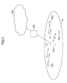
- FIG. 1 shows a mobile communication system according to an embodiment of the present invention.
- the mobile communication system includes a cell 50, user devices 100 1 , 100 2 , and 100 3 (may be collectively called the user device 100) in the cell 50, a base station 200, an access gateway 300, and a core network 400.
- the user devices 100 1 , 100 2 , and 100 3 perform radio communications with the base station 200 according to a MIMO scheme.
- the user device 100 is typically a mobile station, but may instead be implemented as a fixed station.
- the mobile communication system employs SC-FDMA (or DFT-spread OFDM) for uplink.
- the mobile communication system may employ SC-FDMA for downlink.
- FIG. 2 shows a transmitting device for the mobile communication system of this embodiment.
- the transmitting device is included in the user device 100.
- the transmitting device may be included in the base station 200.
- the transmitting device includes a discrete Fourier transform unit (DFT) 21, a frequency domain mapper 22, an inverse fast Fourier transform unit (IFFT) 23, and a guard interval adding unit (+CP) 24.
- DFT discrete Fourier transform unit
- IFFT inverse fast Fourier transform unit
- (+CP guard interval adding unit
- the discrete Fourier transform unit (DFT) 21 receives a symbol sequence to be transmitted and discrete-Fourier-transforms a predetermined number of symbols at once.
- the symbol sequence is typically, but is not limited to, a series of error-correction-coded and data-modulated symbols.
- the discrete Fourier transform unit (DFT) 21 discrete-Fourier-transforms a predetermined number (N DFT ) of symbols at once, and thereby transforms the symbol sequence in the time domain into a signal in the frequency domain.
- N DFT indicates a window size or a block size for discrete Fourier transformation.
- FIG. 3 is a drawing illustrating calculations performed by the DFT 21.
- x 1 at the left end indicates a signal (symbol sequence) to be transmitted from a first transmitting antenna of N TX transmitting antennas.
- Signals x 2 , x 3 ..., x NTX to be transmitted from second, third, ..., N TX transmitting antennas are omitted in FIG. 3 for brevity.
- the symbol sequence x 1 indicates N DFT symbols collectively.
- the symbol sequence x 1 includes N DFT symbols associated with a point on a symbol constellation. Discrete Fourier transformation is equivalent to weighted addition of the N DFT symbols. As shown in FIG.
- a second subcarrier signal w 2 ⁇ x 1 and subsequent subcarrier signals to be mapped to the corresponding subcarriers are obtained.
- the frequency domain mapper 22 shown in FIG. 2 maps the discrete-Fourier-transformed symbols to the corresponding subcarriers. For example, when frequency scheduling is performed for uplink, the frequency domain mapper 22 maps the symbols to available resource units. The available resource units are specified, for example, by scheduling information included in control information received by the transmitting device. Any appropriate method may be used for mapping the symbols to subcarriers. The simplest way may be to map the discrete-Fourier-transformed N DFT symbols to N DFT subcarriers from lower to higher frequencies.
- the inverse fast Fourier transform unit (IFFT) 23 inverse-fast-Fourier-transforms the symbols mapped to the subcarriers to transform the signal in the frequency domain into a signal (transmission symbols) in the time domain.
- the guard interval adding unit (+CP) 24 attaches guard intervals to the transmission symbols and outputs the transmission symbols with the guard intervals to a transmission signal generating unit (not shown) that follows.
- the guard intervals may be generated by a cyclic prefix (CP) scheme.
- FIG. 4 shows a receiving device for the mobile communication system of this embodiment.
- the receiving device includes a guard interval removing unit (-CP) 41, a fast Fourier transform unit (FFT) 42, a frequency domain demapper 43, and a signal detection unit 44.
- -CP guard interval removing unit
- FFT fast Fourier transform unit
- the guard interval removing unit (-CP) 41 removes guard intervals from a received baseband signal.
- the fast Fourier transform unit (FFT) 42 fast-Fourier-transforms the received signal and thereby transforms the received signal in the time domain into a signal in the frequency domain.
- the frequency domain demapper 43 performs a process, which is complementary to the process of the frequency domain mapper 22 of the transmitting device, on the signal in the frequency domain and thereby extracts signal components mapped to subcarriers.
- the signal detection unit 44 narrows down candidates of transmission symbols based on the signal components mapped to the subcarriers and identifies the transmission symbols.
- a transmission symbol sequence to be input to the DFT 21 and transmitted from an n-th transmitting antenna of the transmitting device of FIG. 2 is indicated by x n .
- the transmission symbol sequence x n includes N DFT symbols.
- N DFT indicates a window size (or a block size) for discrete Fourier transformation.
- x n x n ⁇ 1 x n ⁇ 2 ... x nNDFT T
- T indicates transposition
- n indicates a natural number less than or equal to N TX
- N TX indicates the total number of transmitting antennas.
- the received signals y i of the i-th subcarrier may be represented by the following formula:
- H i indicates a channel matrix indicating radio channel conditions regarding the i-th subcarrier.
- the channel matrix H i may be represented by the following formula:
- the channel matrix H i has dimensions of N RX rows and N TX columns.
- N RX indicates the total number of receiving antennas and N TX indicates the total number of transmitting antennas.
- a matrix element h i,pq of the channel matrix H i indicates one of channel conditions (transfer functions), which corresponds to the i-th subcarrier, between a p-th receiving antenna and a q-th transmitting antenna.
- Matrix elements of the channel matrix H i may be obtained, for example, based on reception conditions of a pilot signal.
- w i is a vector representing the weighting factors described above
- 0 NDFT is a 0 vector having N DFT elements.
- x n indicates a signal transmitted from an n-th transmitting antenna.
- N i indicates a noise component regarding the i-th subcarrier.
- Signals represented by formula (1) are input to the signal detection unit 44 of FIG. 4 .
- H ⁇ W Q ⁇ R
- the M-th signal component x M can be fairly easily estimated without taking into account the interference of signals of other subcarriers and/or other transmitting antennas.
- candidates of transmission symbols of the signal component x M are narrowed down based on formula (5).
- the signal component x M corresponds to a signal point on the symbol constellation.
- the smallest S1 (S1 ⁇ C) candidates are selected and other candidates are discarded.
- C indicates the total number of signal points (total number of possible candidates) in the symbol constellation.
- the S1 candidates obtained in the first stage are substituted for x M . There are also C candidates in total for x M-1 . Therefore, survival metrics are calculated as in the first stage for all combinations (S1 ⁇ C) of x M and x M -1.
- e ⁇ 2 ⁇ s M x , s M - 1 x z M - 1 - r M - 1 ⁇ M - 1 ⁇ s M - 1 x + r M - 1 ⁇ M ⁇ s M x 2 + e ⁇ 1 x
- the second term in the right-hand side of (8) indicates the survival metrics obtained in the first stage.
- survival metrics e2(s M (x),s M-1 (x) the survival metrics obtained in the first stage.
- S2 ⁇ S1C the survival metrics obtained in the first stage.
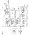
- FIG. 5 shows details of the signal detection unit 44 of FIG. 4 which mainly performs the process as described in ⁇ 4. OPERATIONS>.
- the signal detection unit 44 includes a QR decomposition unit 210, a signal transformation unit 212, a maximum likelihood detection (MLD) unit 214, and a likelihood output unit 215.
- the maximum likelihood detection unit 214 includes four determining units 216-1, 216-2, 216-3, and 216-4. For brevity, only four determining units are shown in FIG. 5 . However, any number of determining units may be provided depending on the number of transmission signals.
- the determining units 216-1, 216-2, 216-3, and 216-4 include substantially the same processing blocks, and therefore the determining unit 216-4 is taken as an example for the descriptions below.
- the determining unit 216-4 includes a symbol replica generating unit 218-4, a square Euclidean distance calculation unit 220-4, and a surviving symbol candidate selecting unit 222-4.
- FIG. 5 and other figures may be implemented by hardware, software, or a combination of them.
- the signal transformation unit 212 multiplies a vector Y including multiple received signals as elements by a conjugate transposed matrix Q H of the unitary matrix Q to transform the received signals.
- the unitary-transformed received signals can be expressed by the product of the upper triangular matrix R and a transmission symbol sequence x.
- the maximum likelihood detection unit 214 narrows down symbol candidates of transmission signals by a maximum likelihood detection (MLD) method.
- the symbol replica generating unit 218-4 of the determining unit 216-4 generates symbol candidates of a transmission signal corresponding to a received signal x 4 by using matrix elements of the upper triangular matrix R.
- the number of symbol candidates is represented by C.
- the square Euclidean distance calculation unit 220-4 calculates square Euclidean distances between a unitary-transformed received signal z i and C symbol candidates.
- the square Euclidean distances represent survival metrics used for calculations of likelihood.
- the surviving symbol candidate selecting unit 222-4 selects S1 ( ⁇ C) symbol candidates based on the square Euclidean distances and outputs the selected symbol candidates as surviving symbol candidates.
- the likelihood output unit 215 calculates the likelihood of symbol candidates output from the surviving symbol candidate selecting unit of the last stage. For example, the likelihood is represented by a log likelihood ratio (LLR).
- LLR log likelihood ratio
- An output from the likelihood output unit 215 indicates signal separation results and is sent to a demodulation unit (e.g., turbo decoder) that follows.
- the present invention is not limited to the above embodiment.
- No indicates average noise power measured at the receiving device
- I indicates a unit matrix of N TX rows and N TX columns.
- the unitary matrix Q has dimensions of N DFT (N TX +N RX ) rows and (N DFT ⁇ N TX ) columns.
- the upper triangular matrix R is a square matrix of (N DET ⁇ N TX ) rows and (N DFT ⁇ N TX ) columns, i.e., has the same dimensions as in the above embodiment.
- the received signals Y are represented by a vector of (N DFT ⁇ N RX ) rows and one column. Meanwhile, in this variation, the received signals Y' are represented by a vector of (N DFT ⁇ (N TX +N RX )) rows and one column where N DFT +N TX components are zeros.
- modified received signal vector Y' and the matrix G is preferable when performing MMSE QR decomposition or ZF QR decomposition.
- H indicates a channel matrix
- W indicates a weight matrix representing weighting in the frequency direction performed by the DFT 21
- F indicates the matrix product of the channel matrix H and the weight matrix W
- x indicates transmission symbols.
- the matrix product F is QR-decomposed and transmission symbols are estimated sequentially according to the M algorithm.
- the number of stages of the M algorithm is N TX ⁇ N DFT .
- the received signals Y are multiplied by the unitary matrix Q H , and symbols are estimated sequentially from the lowest symbol.
- R indicates an upper triangular matrix having N DFT ⁇ N TX rows and N DFT ⁇ N TX columns.
- the product of a matrix A and a column vector s equals the product of a matrix A' obtained by permuting the columns in the matrix A and a column vector s' obtained by permuting elements of the column vector s in a corresponding manner.
- a ⁇ s A ⁇ ⁇ s ⁇
- the column vector x' is obtained by permuting elements of the column vector x with a method corresponding to the permutation method for the matrix F.
- stages of the M algorithm selection of symbol replica candidates is performed for symbols in ascending order of their positions in a transmission symbol vector.
- the order of estimating symbols greatly affects the accuracy of selecting surviving symbol replica candidates.
- the columns of the matrix F are permuted to improve the accuracy of selecting surviving symbol replica candidates and thereby to improve the symbol estimation accuracy.
- Rows and columns of a matrix are relative concepts. Therefore, when transmission symbols are defined by a row vector, rows in the matrix F may be permuted. In other words, although transmission symbols are defined by a column vector in the above examples, the generality of the present invention is not lost.
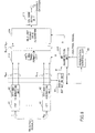
- FIG. 6 shows details of the receiving device of FIG. 4 .
- the receiving device includes the guard interval removing unit(s) (-CP) 41, the fast Fourier transform unit(s) (FFT-and-demapping unit(s)) 42, the QR decomposition unit 210, the signal transformation unit 212, the MLD unit 214, the likelihood output unit 215, a channel estimation unit 62, and a permutation control unit 64.
- the guard interval removing unit (-CP) 41 removes guard intervals from a received baseband signal.
- the fast Fourier transform unit (FFT-and-demapping unit) 42 fast-Fourier-transforms the received signal and thereby transforms the received signal in the time domain into a signal in the frequency domain.
- FFT-and-demapping unit 42 performs both fast Fourier transformation and demapping.
- an FFT unit and a demapping unit may be provided separately.
- the channel estimation unit 62 estimates radio channel conditions of respective subcarriers and obtains a channel matrix H for each of the subcarriers. Accordingly, channel matrices H of all subcarriers form a matrix of N RX ⁇ N DFT rows and N TX ⁇ N DFT columns. Matrix elements of the channel matrix H may be obtained, for example, based on reception conditions of a pilot signal.
- the signal transformation unit 212 multiplies a vector Y including multiple received signals as elements by a conjugate transposed matrix Q H of the unitary matrix Q to transform the received signals.
- the unitary-transformed received signals can be expressed by the product of the upper triangular matrix R and a transmission symbol sequence x.
- the MLD unit 214 narrows down symbol candidates of transmission signals by a maximum likelihood detection (MLD) method.
- the branch metrics are represented by square Euclidean distances between the received signals and the symbol candidates.
- the MLD unit 214 selects, as surviving candidates, a predetermined number (M) of symbol candidates in ascending order of cumulative branch metrics, and goes onto the next stage. In each of N TX ⁇ N DFT stages, the MLD unit 214 calculates branch metrics and selects surviving candidates.
- the likelihood output unit 215 calculates the likelihood of symbol candidates output from the surviving symbol candidate selecting unit of the last stage. For example, the likelihood is represented by a log likelihood ratio (LLR). An output from the likelihood output unit 215 indicates signal separation results and is sent to a demodulation unit that follows.
- LLR log likelihood ratio
- the permutation control unit 64 inputs a control signal to the QR decomposition unit 210.
- the control signal indicates a method of permuting columns of the matrix product F of the channel matrix H and the weight matrix W.
- Formula (9) described above holds regardless of the method of permutation. No single permutation method applies to all cases. Therefore, an appropriate permutation method is determined based on a certain criterion. As described later, the columns of the matrix product F may be permuted based on received power (at the receiving device) of the transmission symbols (first method) and/or based on subcarriers (second method).
- a first method (permutation according to transmitting antennas) of the second variation is described below.
- the columns of the matrix product F is permuted based on received power of transmission symbols at the receiving device.
- symbols estimated in first through (k-1)th stages and a k-th row of the upper triangular matrix R are used.
- the number of code-division-multiplexed transmission symbol sequences corresponds to the number of transmitting antennas.
- the components of a transmission symbol sequence transmitted from one transmitting antenna show the same received signal power.
- a transmitting antenna providing higher received power is identified, and symbols transmitted from the identified transmitting antenna are preferentially estimated prior to symbols from other transmitting antennas.
- Any appropriate method may be used to measure received power levels of symbols from respective transmitting antennas.
- matrix elements of a channel matrix may be used for this purpose. As described above, the channel matrix H i for the i-th subcarrier has dimensions of N RX rows and N TX columns.
- N RX indicates the total number of receiving antennas and N TX indicates the total number of transmitting antennas.
- a matrix element h i,pq of the channel matrix H i indicates one of channel conditions (transfer functions), which corresponds to the i-th subcarrier, between the p-th receiving antenna and the q-th transmitting antenna. Therefore, the sum of
- 2 of all receiving antennas (p 1-N RX ) can be used to estimate the received power of a symbol from the q-th transmitting antenna.
- the columns of the matrix product F' and the components of the transmission symbol sequence x are permuted.
- the components of the transmission symbol sequence x 1 are moved to lower positions in the column vector to give priority to symbols from the first transmitting antenna.
- the order in which the subcarrier components x 11 , x 12 , and x 13 in the transmission symbol sequence x 1 are estimated is not uniquely determined yet.
- the subcarrier components x 11 , x 12 , and x 13 may be estimated in ascending order of subcarrier numbers.
- the subcarrier components may also be permuted in any other order.
- the numbers of antennas and the number of subcarriers are just examples, and any other values may be used.
- a second method of the second variation (permutation according to subcarriers) is described below.
- a combination of symbols with high fading correlation tend to cause a serious error.
- High fading correlation between symbols indicates that the symbols are subject to a similar level of fading.
- Low fading correlation between symbols indicates that the symbols are subject to different levels of fading.
- the fading correlation is represented by a value greater than or equal to 0 and less than or equal to 1. The fading correlation increases as the value nears 1 and decreases as the value nears 0.
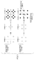
- FIG. 7 is a drawing used to describe that the level of difficulty in determining a combination of symbols varies depending on the degree of fading correlation.
- N TX and the number of receiving antennas N RX are both 2.
- a symbol 1 (x 1 ) is transmitted from a first transmitting antenna.
- a symbol 2 (x 2 ) is transmitted from a second transmitting antenna.
- the symbols transmitted from the transmitting antennas are data modulated by QPSK.
- each symbol is one of four signal points on a signal constellation. In other words, there are four candidates for each of the symbols 1 and 2. Therefore, the number of combinations is 16.
- the symbols 1 and 2 are received at the receiving device as a combined signal (r i1 , r i2 ).
- permutation is performed such that symbols subject to a similar level of fading are not estimated consecutively.
- the order of symbol detection is determined such that after a first symbol is estimated, a second symbol subject to a different level of fading from that of the first symbol is estimated. More specifically, the order of symbol detection is controlled such that a transmission symbol from a first transmitting antenna is estimated and then a transmission symbol from a second transmitting antenna is estimated.
- the degree of fading correlation may be determined by any appropriate method.
- the degree of fading correlation may be determined based on the similarity of amplitudes and phases of matrix elements h i,pq of the channel matrix. Taking the i-th subcarrier as an example, when pilot signals with a size 1 are transmitted, respectively, from an a-th transmitting antenna and a b-th transmitting antenna and received by a p-th receiving antenna, the fading correlation between the two received signals may be evaluated by h i,pa *h i,pb (where * indicates complex conjugate). Needless to say, any other appropriate method may be used to determine the degree of fading correlation.
- symbols from transmitting antennas may be estimated subcarrier by subcarrier.
- signals transmitted from the same antenna are subject to a similar level of fading and therefore have high fading correlation.
- signals transmitted from different antennas are subject to different levels of fading and therefore have low fading correlation.
- N TX transmission symbols (subcarrier components) transmitted using the i-th subcarrier are estimated, next N TX transmission symbols transmitted using the i+1-th subcarrier are estimated. Similar steps are repeated, and symbols with low fading correlation are estimated successively.
- subcarriers are selected sequentially in ascending order of subcarrier numbers and for each selected subcarrier, symbols transmitted from all transmitting antennas are estimated.
- subcarrier components are estimated in ascending order of subcarrier numbers.
- the order of estimating subcarrier components is not limited to the ascending order of subcarrier numbers.
- the numbers of antennas and the number of subcarriers are just examples, and any other values may be used.
Landscapes
- Engineering & Computer Science (AREA)
- Computer Networks & Wireless Communication (AREA)
- Signal Processing (AREA)
- Power Engineering (AREA)
- Radio Transmission System (AREA)
- Mobile Radio Communication Systems (AREA)
Abstract
Description
- The present invention generally relates to mobile communication technologies. More particularly, the present invention relates to a mobile communication system, a receiving device, and a method adapted for single-carrier multiple input multiple output (MIMO) transmission.
- In multicarrier transmission schemes, a frequency band is divided into multiple narrow frequency bands (subcarriers) and separate signals are transmitted using the subcarriers. For example, in orthogonal frequency division multiple access (OFDMA), subcarriers are arranged such that they become orthogonal to each other to improve frequency efficiency and to achieve high-speed, high-volume communications. OFDMA makes it possible to effectively reduce inter-subcarrier interference. This in turn makes it possible to concurrently transmit signals using subcarriers and to increase the symbol length. Also with OFDMA, it is possible to effectively reduce multipath interference by using a relatively long guard interval.
- With multicarrier transmission schemes, however, fairly-high peak power is instantaneously necessary for transmission because signals mapped to subcarriers overlap each other in the time domain. In other words, with multicarrier transmission schemes, the peak-to-average power ratio (PAPR) may become fairly high. This is not preferable particularly for mobile terminals.
- Generally, single-carrier transmission schemes have an advantage in terms of reducing the PAPR. Particularly, single-carrier transmission schemes such as single-carrier frequency division multiple access (SC-FDMA) and discrete Fourier transform (DFT) spread OFDM also make it possible to efficiently use a wide frequency band. In SC-FDMA, a transmission signal is Fourier-transformed and mapped to subcarriers, and the mapped signal is inverse-Fourier-transformed and wirelessly transmitted. At the receiving end, a received signal is Fourier-transformed, signal components mapped to the subcarriers are extracted, and transmission symbols are estimated. Such single-carrier transmission schemes are preferable in terms of efficiently using a frequency band while reducing the PAPR.
- Meanwhile, with single-carrier transmission schemes where subcarriers with a relatively large bandwidth are used, multipath interference tends to occur. Multipath interference increases as the transmission rate increases. For example, multipath interference becomes particularly prominent when the data modulation level is high or a MIMO multiplexing scheme is used. Increase in multipath interference in turn reduces the detection accuracy of signals at the receiving end.
- Let us assume that the number of transmitting antennas is N, the data modulation level is B (e.g., when 16 QAM is used, B=4), the expected number of multipaths is P, and a maximum likelihood detection (MLD) method is used for signal detection (for a QRM-MLD method, see, for example, K. J. Kim, et al., "Joint channel estimation and data detection algorithm for MIMO-OFDM systems", Proc. 36th Asilomar Conference on Signals, Systems and Computers, Nov. 2002). As described above, OFDMA makes it possible to effectively reduce inter-subcarrier interference and to sufficiently reduce multipath interference within a guard interval. Therefore, with OFDMA, the total number of symbol candidates that need to be examined at the receiving end is represented by the following formula:

- Meanwhile, with a single-carrier transmission scheme where multipath interference cannot be ignored, the total number of symbol candidates that need to be examined is represented by the following formula:

- Thus, with a single-carrier transmission scheme, the number of candidates increases exponentially according to the number of multipaths and as a result, the computational complexity for signal detection increases. This in turn makes it difficult to employ an MLD method, which provides high detection accuracy but require high computational complexity, together with a single-carrier MIMO transmission scheme. Signal detection methods such as a zero forcing (ZF) method and a minimum mean squared error (MMSE) method require low computational complexity, but may reduce the signal detection accuracy. To achieve desired signal quality (desired SINR) when the signal detection accuracy at the receiving end is low, it is necessary to increase the transmission power of signals. However, since one purpose of employing a single-carrier transmission scheme is to reduce the PAPR and thereby to save battery energy, it is not preferable to increase the transmission power.
- One object of the present invention is to improve the signal detection accuracy at a receiving end in a mobile communication system employing a single-carrier MIMO scheme and SC-FDMA.
- An aspect of the present invention provides a mobile communication system employing a single-carrier MIMO transmission scheme and including a transmitting device and a receiving device.
- The transmitting device includes a mapping unit configured to map Fourier-transformed and weighted symbols in a transmission symbol sequence to subcarriers, an inverse Fourier transform unit configured to inverse-Fourier-transform the mapped symbols, and a transmitting unit configured to transmit a signal including the inverse-Fourier-transformed symbols from multiple transmitting antennas.
- The receiving device includes an extracting unit configured to Fourier-transform signals received by multiple receiving antennas and to extract signal components mapped to the subcarriers from the signals, and a signal detection unit configured to estimate the symbols transmitted via the subcarriers by applying a QR decomposition algorithm to the extracted signal components.
- The signal detection unit includes a decomposition unit configured to obtain a unitary matrix such that the product of the unitary matrix, a weight matrix determining a correspondence between the transmission symbol sequence and the subcarriers, and a channel matrix indicating radio channel conditions between the transmitting antennas and the receiving antennas becomes a triangular matrix; and an estimation unit configured to estimate candidates of the symbols transmitted from the transmitting antennas based on the triangular matrix and a vector obtained by multiplying a received vector, which includes the signal components received by the receiving antennas, by the unitary matrix.
- An aspect of the present invention makes it possible to improve the signal detection accuracy at a receiving end in a mobile communication system employing a single-carrier MIMO scheme and SC-FDMA.
-
-
FIG. 1 is a drawing illustrating a mobile communication system according to an embodiment of the present invention; -
FIG. 2 is a partial block diagram of a transmitting device; -
FIG. 3 is a drawing illustrating calculations performed by a DFT 21; -
FIG. 4 is a partial block diagram of a receiving device; -
FIG. 5 is a drawing illustrating an exemplary configuration of a signal detection unit; -
FIG. 6 is a functional block diagram illustrating details of a receiving device; and -
FIG. 7 is a drawing used to describe that the level of difficulty in determining a combination of symbols varies depending on the degree of fading correlation. -
- 50
- Cell
- 100
- User device (UE)
- 200
- Base station (eNB)
- 300
- Access gateway
- 400
- Core network
- 21
- Discrete Fourier transform unit (DFT)
- 22
- Frequency domain mapper
- 23
- Inverse fast Fourier transform unit (IFFT)
- 24
- Guard interval adding unit
- 41
- Guard interval removing unit (-CP)
- 42
- Fast Fourier transform unit (FFT)
- 43
- Frequency domain demapper
- 44
- Signal detection unit
- 62
- Channel estimation unit
- 64
- Permutation control unit
- 210
- QR decomposition unit
- 212
- Signal transformation unit
- 214
- Maximum likelihood detection unit
- 215
- Likelihood output unit
- 216-1 - 261-4
- Determining unit
- An aspect of the present invention provides a receiving device for a mobile communication system employing a single-carrier MIMO transmission scheme and SC-FDMA. The receiving device includes an extracting unit configured to Fourier-transform signals received by multiple receiving antennas and to extract signal components mapped to subcarriers from the signals, and a signal detection unit configured to estimate symbols transmitted via the subcarriers by applying a QR decomposition algorithm to the extracted signal components. The signal detection unit includes a decomposition unit configured to obtain a unitary matrix QH such that the product of the unitary matrix QH, a weight matrix W determining a correspondence between a transmission symbol sequence and the subcarriers, and a channel matrix H indicating radio channel conditions between transmitting antennas and the receiving antennas becomes a triangular matrix R; and an estimation unit configured to estimate candidates x of the symbols transmitted from the transmitting antennas based on the triangular matrix R and a vector obtained by multiplying a received vector Y, which includes the signal components received by the receiving antennas, by the unitary matrix QH.
- Using a QR decomposition algorithm at the receiving end in a mobile communication system employing a single-carrier MIMO scheme makes it possible to reduce the computational complexity in signal detection as well as to improve the signal detection accuracy. Improved signal detection accuracy in turn makes it possible to reduce transmission power necessary to maintain desired quality. This approach is particularly preferable when the transmitting end is a user device. Using a QR decomposition algorithm also makes it possible to efficiently perform an equalization process in the frequency domain and a signal separation process based on, for example, MLD.
- The signal detection unit may further include a determining unit configured to calculate metrics for the respective candidates of the symbols and to narrow down the candidates based on the metrics. The metrics may indicate square Euclidean distances on a symbol constellation between received symbols and the candidates of the symbols. Thus, reducing the computational complexity in signal detection makes it possible to use an MLD method together with a single-carrier MIMO transmission scheme. This in turn makes it possible to further improve the signal detection accuracy.
- The receiving device may further include a permutation control unit configured to input a control signal for permuting rows or columns of a matrix product of the channel matrix and the weight matrix to the decomposition unit. In this case, the decomposition unit may be configured to obtain the triangular matrix and the unitary matrix such that the product of the triangular matrix and the unitary matrix equals the matrix product the rows or the columns of which are permuted according to the control signal.
- The permutation control unit may be configured to generate the control signal such that when the estimation unit estimates the symbols according to an M algorithm, the symbols from one of the transmitting antennas corresponding to higher received power are estimated prior to the symbols from another one of the transmitting antennas corresponding to lower received power.
- Alternatively, the permutation control unit may be configured to generate the control signal such that the estimation unit estimates a first subcarrier component of the symbols transmitted from a first one of the transmitting antennas and then estimates a first subcarrier component of the symbols transmitted from a second one of the transmitting antennas.
- Although specific values are used in the descriptions below to facilitate the understanding of the present invention, the values are just examples and other appropriate values may also be used unless otherwise mentioned.
- Below, the following aspects of the present invention are described as preferred embodiments:
- 1. System
- 2. Transmitting device
- 3. Receiving device
- 4. Operations
- 5. Details of signal detection unit
- 6. First variation
- 7. Second variation
- 8. Second variation - first method, second method
-
FIG. 1 shows a mobile communication system according to an embodiment of the present invention. As shown inFIG. 1 , the mobile communication system includes acell 50,user devices cell 50, abase station 200, anaccess gateway 300, and acore network 400. In this embodiment, it is assumed that one or more of theuser devices base station 200 according to a MIMO scheme. Theuser device 100 is typically a mobile station, but may instead be implemented as a fixed station. It is also assumed that the mobile communication system employs SC-FDMA (or DFT-spread OFDM) for uplink. Alternatively, the mobile communication system may employ SC-FDMA for downlink. -
FIG. 2 shows a transmitting device for the mobile communication system of this embodiment. In this embodiment, it is assumed that the transmitting device is included in theuser device 100. Alternatively, the transmitting device may be included in thebase station 200. As shown inFIG. 2 , the transmitting device includes a discrete Fourier transform unit (DFT) 21, afrequency domain mapper 22, an inverse fast Fourier transform unit (IFFT) 23, and a guard interval adding unit (+CP) 24. - The discrete Fourier transform unit (DFT) 21 receives a symbol sequence to be transmitted and discrete-Fourier-transforms a predetermined number of symbols at once. The symbol sequence is typically, but is not limited to, a series of error-correction-coded and data-modulated symbols. The discrete Fourier transform unit (DFT) 21 discrete-Fourier-transforms a predetermined number (NDFT) of symbols at once, and thereby transforms the symbol sequence in the time domain into a signal in the frequency domain. Here, NDFT indicates a window size or a block size for discrete Fourier transformation.
-
FIG. 3 is a drawing illustrating calculations performed by theDFT 21. InFIG. 3 , x1 at the left end indicates a signal (symbol sequence) to be transmitted from a first transmitting antenna of NTX transmitting antennas. Signals x2, x3 ..., xNTX to be transmitted from second, third, ..., NTX transmitting antennas are omitted inFIG. 3 for brevity. Here, the symbol sequence x1 indicates NDFT symbols collectively. For example, the symbol sequence x1 includes NDFT symbols associated with a point on a symbol constellation. Discrete Fourier transformation is equivalent to weighted addition of the NDFT symbols. As shown inFIG. 3 , the symbol sequence x1 including the NDFT symbols (= x11, x12, ..., x1NDFT) is converted by a serial-parallel converter (S/P), each of the NEFT symbols is multiplied by a predetermined weight w1j, and the multiplied symbols are added together to obtain a first subcarrier signal w1 · x1. Similarly, a second subcarrier signal w2·x1 and subsequent subcarrier signals to be mapped to the corresponding subcarriers are obtained. Through the above calculations, NDFT subcarrier components for all subcarriers to be transmitted at once from the first transmitting antenna are prepared. Similar calculations are also performed for signals x2 through xNTX to be transmitted from other transmitting antennas. - The
frequency domain mapper 22 shown inFIG. 2 maps the discrete-Fourier-transformed symbols to the corresponding subcarriers. For example, when frequency scheduling is performed for uplink, thefrequency domain mapper 22 maps the symbols to available resource units. The available resource units are specified, for example, by scheduling information included in control information received by the transmitting device. Any appropriate method may be used for mapping the symbols to subcarriers. The simplest way may be to map the discrete-Fourier-transformed NDFT symbols to NDFT subcarriers from lower to higher frequencies. - The inverse fast Fourier transform unit (IFFT) 23 inverse-fast-Fourier-transforms the symbols mapped to the subcarriers to transform the signal in the frequency domain into a signal (transmission symbols) in the time domain.
- The guard interval adding unit (+CP) 24 attaches guard intervals to the transmission symbols and outputs the transmission symbols with the guard intervals to a transmission signal generating unit (not shown) that follows. The guard intervals may be generated by a cyclic prefix (CP) scheme.
-
FIG. 4 shows a receiving device for the mobile communication system of this embodiment. As shown inFIG. 4 , the receiving device includes a guard interval removing unit (-CP) 41, a fast Fourier transform unit (FFT) 42, afrequency domain demapper 43, and asignal detection unit 44. - The guard interval removing unit (-CP) 41 removes guard intervals from a received baseband signal.
- The fast Fourier transform unit (FFT) 42 fast-Fourier-transforms the received signal and thereby transforms the received signal in the time domain into a signal in the frequency domain.
- The
frequency domain demapper 43 performs a process, which is complementary to the process of thefrequency domain mapper 22 of the transmitting device, on the signal in the frequency domain and thereby extracts signal components mapped to subcarriers. - The
signal detection unit 44 narrows down candidates of transmission symbols based on the signal components mapped to the subcarriers and identifies the transmission symbols. - Operations of the
signal detection unit 44 are described below. In the descriptions below, it is assumed that a transmission symbol sequence to be input to theDFT 21 and transmitted from an n-th transmitting antenna of the transmitting device ofFIG. 2 is indicated by xn. The transmission symbol sequence xn includes NDFT symbols. NDFT indicates a window size (or a block size) for discrete Fourier transformation.
- In this formula, T indicates transposition, n indicates a natural number less than or equal to NTX, and NTX indicates the total number of transmitting antennas.
- Weighting factors wi to be used for an i-th subcarrier (i indicates a natural number less than or equal to NDFT) are represented by the following formula:

- All signals received at a time via NRX receiving antennas of the receiving device of
FIG. 3 are indicated by the following formula:
- In this formula, yi indicates signals of an i-th subcarrier received by the respective NRX receiving antennas and is represented as follows:

- Also, the received signals yi of the i-th subcarrier may be represented by the following formula:

- In the above formula, Hi indicates a channel matrix indicating radio channel conditions regarding the i-th subcarrier. The channel matrix Hi may be represented by the following formula:

- The channel matrix Hi has dimensions of NRX rows and NTX columns. NRX indicates the total number of receiving antennas and NTX indicates the total number of transmitting antennas. A matrix element hi,pq of the channel matrix Hi indicates one of channel conditions (transfer functions), which corresponds to the i-th subcarrier, between a p-th receiving antenna and a q-th transmitting antenna. Matrix elements of the channel matrix Hi may be obtained, for example, based on reception conditions of a pilot signal.
- Also in the above formula, wi is a vector representing the weighting factors described above, and 0NDFT is a 0 vector having NDFT elements.
- Also, xn indicates a signal transmitted from an n-th transmitting antenna.
- Further, Ni indicates a noise component regarding the i-th subcarrier.
- All sets of NDFT subcarrier components received by the NRX receiving antennas are represented by the following formula:


- Signals represented by formula (1) are input to the
signal detection unit 44 ofFIG. 4 . - First, a unitary matrix Q and an upper triangular matrix R are obtained such that the product of a channel matrix H and a weight matrix W is expressed by the product of the unitary matrix Q and the upper triangular matrix R (HW=QR).

- The upper triangular matrix R is a square matrix of M rows and M columns (M=NDFT×NTX) where matrix elements rij (i>j) are all zero.

- In the present application, when a matrix A is a unitary matrix, the matrix A satisfies AHA=AAH=1. Accordingly, the matrix A is not necessarily a square matrix. Also in the present application, a normal "H" indicates a channel matrix and a superscript "H" indicates conjugate transposition.
- When both sides of formula (1) are multiplied by QH from the left, the left-hand side can be expressed as follows:

- Meanwhile, the right-hand side can be expressed as follows:

- Therefore, when the noise is ignored, the unitary-transformed received signals z can be represented by R×x.

- Since R is an upper triangular matrix, an M-th signal component (M=NDFT×NTX) can be expressed as follows:

- This indicates that the M-th signal component xM can be fairly easily estimated without taking into account the interference of signals of other subcarriers and/or other transmitting antennas.
- In a first stage of a transmission symbol estimation process, candidates of transmission symbols of the signal component xM are narrowed down based on formula (5). Here, the signal component xM corresponds to a signal point on the symbol constellation. For example, there are four possibilities (or candidates) when QPSK is used, or there are 64 possibilities (or candidates) when 64 QAM is used. For each of all possible candidates, the square Euclidean distance between the unitary-transformed received signal zM and rMM×(candidate of xM=sM(x)) is calculated as a survival metric.

- Of the survival metrics obtained, the smallest S1 (S1 ≦ C) candidates are selected and other candidates are discarded. Here, C indicates the total number of signal points (total number of possible candidates) in the symbol constellation.
- In a second stage of the transmission symbol estimation process, the following formula obtained from formula (4) is used:

- The S1 candidates obtained in the first stage are substituted for xM. There are also C candidates in total for xM-1. Therefore, survival metrics are calculated as in the first stage for all combinations (S1×C) of xM and xM-1.

- The second term in the right-hand side of (8) indicates the survival metrics obtained in the first stage. Of the survival metrics e2(sM(x),sM-1(x)), the smallest S2 (S2≦S1C) candidates are selected and other candidates are discarded.
- Similar steps are repeated and the number of survival metrics is increased stage by stage. Then, in the last stage, a combination of transmission symbols corresponding to the smallest metric is estimated as the actually transmitted symbols.
-
FIG. 5 shows details of thesignal detection unit 44 ofFIG. 4 which mainly performs the process as described in <4. OPERATIONS>. Thesignal detection unit 44 includes aQR decomposition unit 210, asignal transformation unit 212, a maximum likelihood detection (MLD)unit 214, and alikelihood output unit 215. The maximumlikelihood detection unit 214 includes four determining units 216-1, 216-2, 216-3, and 216-4. For brevity, only four determining units are shown inFIG. 5 . However, any number of determining units may be provided depending on the number of transmission signals. The determining units 216-1, 216-2, 216-3, and 216-4 include substantially the same processing blocks, and therefore the determining unit 216-4 is taken as an example for the descriptions below. The determining unit 216-4 includes a symbol replica generating unit 218-4, a square Euclidean distance calculation unit 220-4, and a surviving symbol candidate selecting unit 222-4. - Each processing element in
FIG. 5 and other figures may be implemented by hardware, software, or a combination of them. - The
QR decomposition unit 210 obtains a unitary matrix Q and an upper triangular matrix R such that the product of a channel matrix H and a weight matrix W is expressed by the product of the unitary matrix Q and the upper triangular matrix R (HW=QR). - The
signal transformation unit 212 multiplies a vector Y including multiple received signals as elements by a conjugate transposed matrix QH of the unitary matrix Q to transform the received signals. When the noise is ignored, the unitary-transformed received signals can be expressed by the product of the upper triangular matrix R and a transmission symbol sequence x.
- The maximum
likelihood detection unit 214 narrows down symbol candidates of transmission signals by a maximum likelihood detection (MLD) method. The symbol replica generating unit 218-4 of the determining unit 216-4 generates symbol candidates of a transmission signal corresponding to a received signal x4 by using matrix elements of the upper triangular matrix R. The number of symbol candidates is represented by C. - The square Euclidean distance calculation unit 220-4 calculates square Euclidean distances between a unitary-transformed received signal zi and C symbol candidates. The square Euclidean distances represent survival metrics used for calculations of likelihood.
- The surviving symbol candidate selecting unit 222-4 selects S1 (≦ C) symbol candidates based on the square Euclidean distances and outputs the selected symbol candidates as surviving symbol candidates.
- The
likelihood output unit 215 calculates the likelihood of symbol candidates output from the surviving symbol candidate selecting unit of the last stage. For example, the likelihood is represented by a log likelihood ratio (LLR). An output from thelikelihood output unit 215 indicates signal separation results and is sent to a demodulation unit (e.g., turbo decoder) that follows. - In the above embodiment, F=H×W is QR-decomposed. However, the present invention is not limited to the above embodiment. For example, a matrix G as shown by the following formula may be QR-decomposed:

- In the above formula, No indicates average noise power measured at the receiving device, and I indicates a unit matrix of NTX rows and NTX columns. In this case, the unitary matrix Q has dimensions of NDFT(NTX+NRX) rows and (NDFT×NTX) columns. The upper triangular matrix R is a square matrix of (NDET×NTX) rows and (NDFT×NTX) columns, i.e., has the same dimensions as in the above embodiment.
- In the above embodiment, the received signals Y are represented by a vector of (NDFT×NRX) rows and one column. Meanwhile, in this variation, the received signals Y' are represented by a vector of (NDFT×(NTX+NRX)) rows and one column where NDFT+NTX components are zeros.

- Using the modified received signal vector Y' and the matrix G is preferable when performing MMSE QR decomposition or ZF QR decomposition.
- As described in <4. OPERATIONS>, when symbols are transmitted using NDFT subcarriers from NTX transmitting antennas, the received signals Y are expressed as follows without considering the noise:

- In formula (9), H indicates a channel matrix, W indicates a weight matrix representing weighting in the frequency direction performed by the
DFT 21, F indicates the matrix product of the channel matrix H and the weight matrix W, and x indicates transmission symbols. In the above descriptions of operations, the matrix product F is QR-decomposed and transmission symbols are estimated sequentially according to the M algorithm. The number of stages of the M algorithm is NTX×NDFT. The received signals Y are multiplied by the unitary matrix QH, and symbols are estimated sequentially from the lowest symbol.
- In formula (10), R indicates an upper triangular matrix having NDFT×NTX rows and NDFT×NTX columns.
- Meanwhile, the product of a matrix A and a column vector s equals the product of a matrix A' obtained by permuting the columns in the matrix A and a column vector s' obtained by permuting elements of the column vector s in a corresponding manner.

- For example, when the matrix A has two rows and two columns and the column vector s has two rows and one column (s=(s1 s2)T), the following formula is true:

- This relationship also holds for higher-dimensional matrices. Permutation of the columns in the matrix may be performed in any manner as long as the elements of the column vector are permuted in the corresponding manner. In the second variation, the above described QR decomposition is performed based on this characteristic.

- The matrix F' is obtained by permuting columns in the matrix F (=H×W) with a given method. The column vector x' is obtained by permuting elements of the column vector x with a method corresponding to the permutation method for the matrix F.
- In stages of the M algorithm, selection of symbol replica candidates is performed for symbols in ascending order of their positions in a transmission symbol vector. The order of estimating symbols greatly affects the accuracy of selecting surviving symbol replica candidates. In the second variation, the columns of the matrix F are permuted to improve the accuracy of selecting surviving symbol replica candidates and thereby to improve the symbol estimation accuracy.
- Rows and columns of a matrix are relative concepts. Therefore, when transmission symbols are defined by a row vector, rows in the matrix F may be permuted. In other words, although transmission symbols are defined by a column vector in the above examples, the generality of the present invention is not lost.
-
FIG. 6 shows details of the receiving device ofFIG. 4 . As shown inFIG. 6 , the receiving device includes the guard interval removing unit(s) (-CP) 41, the fast Fourier transform unit(s) (FFT-and-demapping unit(s)) 42, theQR decomposition unit 210, thesignal transformation unit 212, theMLD unit 214, thelikelihood output unit 215, achannel estimation unit 62, and apermutation control unit 64. - The guard interval removing unit (-CP) 41 removes guard intervals from a received baseband signal.
- The fast Fourier transform unit (FFT-and-demapping unit) 42 fast-Fourier-transforms the received signal and thereby transforms the received signal in the time domain into a signal in the frequency domain. Here, for descriptive purposes, it is assumed that the fast Fourier transform unit (FFT-and-demapping unit) 42 performs both fast Fourier transformation and demapping. Alternatively, an FFT unit and a demapping unit may be provided separately.
- The
channel estimation unit 62 estimates radio channel conditions of respective subcarriers and obtains a channel matrix H for each of the subcarriers. Accordingly, channel matrices H of all subcarriers form a matrix of NRX×NDFT rows and NTX×NDFT columns. Matrix elements of the channel matrix H may be obtained, for example, based on reception conditions of a pilot signal. - The
QR decomposition unit 210 obtains a unitary matrix Q and an upper triangular matrix R based on the channel matrix H, the weight matrix W, and a control signal from thepermutation control unit 64. More particularly, theQR decomposition unit 210 obtains a matrix F' by permuting columns of the matrix product F of the channel matrix H and the weight matrix W according to the control signal. Then, theQR decomposition unit 210 obtains a unitary matrix Q and an upper triangular matrix R such that the matrix F' is expressed by the product of the unitary matrix Q and the upper triangular matrix R (F'=QR). - The
signal transformation unit 212 multiplies a vector Y including multiple received signals as elements by a conjugate transposed matrix QH of the unitary matrix Q to transform the received signals. When the noise is ignored, the unitary-transformed received signals can be expressed by the product of the upper triangular matrix R and a transmission symbol sequence x.
- The
MLD unit 214 narrows down symbol candidates of transmission signals by a maximum likelihood detection (MLD) method. TheMLD unit 214 calculates branch metrics for the received signals multiplied by the unitary matrix QH (QHY(=Rx)) sequentially from lower symbols. The branch metrics are represented by square Euclidean distances between the received signals and the symbol candidates. TheMLD unit 214 selects, as surviving candidates, a predetermined number (M) of symbol candidates in ascending order of cumulative branch metrics, and goes onto the next stage. In each of NTX×NDFT stages, theMLD unit 214 calculates branch metrics and selects surviving candidates. - The
likelihood output unit 215 calculates the likelihood of symbol candidates output from the surviving symbol candidate selecting unit of the last stage. For example, the likelihood is represented by a log likelihood ratio (LLR). An output from thelikelihood output unit 215 indicates signal separation results and is sent to a demodulation unit that follows. - The
permutation control unit 64 inputs a control signal to theQR decomposition unit 210. The control signal indicates a method of permuting columns of the matrix product F of the channel matrix H and the weight matrix W. Formula (9) described above holds regardless of the method of permutation. No single permutation method applies to all cases. Therefore, an appropriate permutation method is determined based on a certain criterion. As described later, the columns of the matrix product F may be permuted based on received power (at the receiving device) of the transmission symbols (first method) and/or based on subcarriers (second method). - A first method (permutation according to transmitting antennas) of the second variation is described below. In the first method, the columns of the matrix product F is permuted based on received power of transmission symbols at the receiving device. In a k-th stage (1 ≦ k ≦ NTXNSF) in a symbol estimation process according to the M algorithm, symbols estimated in first through (k-1)th stages and a k-th row of the upper triangular matrix R are used. This indicates that selection of surviving symbol replica candidates for the first through k-th transmission symbols is performed based on the sum of squares (signal power) of elements from the (NTXNSF-k+1)th row to the NTXNSF-th row of the (NTXNSF-k+1)th column in the matrix R. Therefore, in the earlier stages (particularly in the first stage), the estimation process is easier, but the probability of selecting wrong symbol replica candidates is also high. In the first method, the received signal power levels of transmission symbols from the respective transmitting antennas are measured and higher priorities are given to transmission symbols with higher received signal power levels. This is because the probability of selecting wrong symbol replica candidates decreases as the received power increases. The orders of the columns of the matrix product F and the (subcarrier) components of the transmission symbol sequence x are determined such that the above priorities are achieved.
- In a DFT-MIMO multiplexing scheme employing frequency domain spreading of this method, the number of code-division-multiplexed transmission symbol sequences corresponds to the number of transmitting antennas. The components of a transmission symbol sequence transmitted from one transmitting antenna show the same received signal power. In this method, a transmitting antenna providing higher received power is identified, and symbols transmitted from the identified transmitting antenna are preferentially estimated prior to symbols from other transmitting antennas. Any appropriate method may be used to measure received power levels of symbols from respective transmitting antennas. For example, matrix elements of a channel matrix may be used for this purpose. As described above, the channel matrix Hi for the i-th subcarrier has dimensions of NRX rows and NTX columns. NRX indicates the total number of receiving antennas and NTX indicates the total number of transmitting antennas. A matrix element hi,pq of the channel matrix Hi indicates one of channel conditions (transfer functions), which corresponds to the i-th subcarrier, between the p-th receiving antenna and the q-th transmitting antenna. Therefore, the sum of |hi,pq|2 of all receiving antennas (p=1-NRX) can be used to estimate the received power of a symbol from the q-th transmitting antenna. Let us assume that NTX=NRX=2 and NDFT=3. In this case, the following formulas are true for the i-th subcarriers (i=1, 2, 3):


- The received power of symbols from the first transmitting antenna can be evaluated by the following formula:

- Similarly, the received power of symbols from the second transmitting antenna can be evaluated by the following formula:
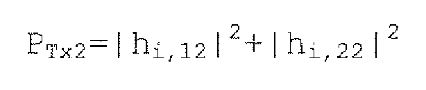
- Here, let us assume that the received power of the symbols from the first transmitting antenna is greater than the received power of the symbols from the second transmitting antenna (PTX1>PTX2). According to the first method, symbols x1=(x11 x12 x13)T from the first transmitting antenna need to be estimated in preference to symbols x2=(x21 x22 x23)T from the second transmitting antenna. For this purpose, the columns of the matrix product F' and the components of the transmission symbol sequence x are permuted. For example, a transmission symbol sequence x' after permutation is represented by the following formula:

- As shown by the above formula, the components of the transmission symbol sequence x1 are moved to lower positions in the column vector to give priority to symbols from the first transmitting antenna. At this stage, the order in which the subcarrier components x11, x12, and x13 in the transmission symbol sequence x1 are estimated is not uniquely determined yet. For example, the subcarrier components x11, x12, and x13 may be estimated in ascending order of subcarrier numbers. In this case, the transmission symbol sequence x' after permutation is represented by the following formula:

- The subcarrier components may also be permuted in any other order.
- In the above descriptions, the numbers of antennas and the number of subcarriers are just examples, and any other values may be used.
- A second method of the second variation (permutation according to subcarriers) is described below. When selecting surviving symbol replica candidates using the M algorithm, a combination of symbols with high fading correlation tend to cause a serious error. High fading correlation between symbols indicates that the symbols are subject to a similar level of fading. Low fading correlation between symbols indicates that the symbols are subject to different levels of fading. For example, the fading correlation is represented by a value greater than or equal to 0 and less than or equal to 1. The fading correlation increases as the value nears 1 and decreases as the value nears 0.
-
FIG. 7 is a drawing used to describe that the level of difficulty in determining a combination of symbols varies depending on the degree of fading correlation. Here, it is assumed that the number of transmitting antennas NTX and the number of receiving antennas NRX are both 2. A symbol 1 (x1) is transmitted from a first transmitting antenna. A symbol 2 (x2) is transmitted from a second transmitting antenna. It is assumed that the symbols transmitted from the transmitting antennas are data modulated by QPSK. In this case, each symbol is one of four signal points on a signal constellation. In other words, there are four candidates for each of thesymbols symbols 

- When the fading correlation is low, the symbols are subject to different levels of fading. In this case, as shown in upper right of
FIG. 7 , 16 combinations of symbols for the combined received signal are all distinguishable. Therefore, the accuracy in selecting a combination of symbols is high. Meanwhile, when the fading correlation is high, the symbols are subject to a similar level of fading. In the lower part ofFIG. 7 , it is assumed that thesymbols FIG. 7 , 16 combinations of symbols for the combined received signal are only partially distinguishable. In this example, only nine combinations are distinguishable due to overlapping of symbols. The likelihood of overlapping symbols indicated by "two overlapping symbols" and "four overlapping symbols" inFIG. 7 cannot be determined by just comparing their square Euclidean distances or phases. - In a DFT-MIMO multiplexing scheme employing frequency domain spreading, code-division-multiplexed symbols transmitted from the same antenna tend to undergo a similar level of fading (the fading correlation tends to become high).
- In the second method, for the above reasons, permutation is performed such that symbols subject to a similar level of fading are not estimated consecutively. In other words, the order of symbol detection is determined such that after a first symbol is estimated, a second symbol subject to a different level of fading from that of the first symbol is estimated. More specifically, the order of symbol detection is controlled such that a transmission symbol from a first transmitting antenna is estimated and then a transmission symbol from a second transmitting antenna is estimated.
- The degree of fading correlation may be determined by any appropriate method. For example, the degree of fading correlation may be determined based on the similarity of amplitudes and phases of matrix elements hi,pq of the channel matrix. Taking the i-th subcarrier as an example, when pilot signals with a
size 1 are transmitted, respectively, from an a-th transmitting antenna and a b-th transmitting antenna and received by a p-th receiving antenna, the fading correlation between the two received signals may be evaluated by hi,pa*hi,pb (where * indicates complex conjugate). Needless to say, any other appropriate method may be used to determine the degree of fading correlation. - With the order of symbol detection determined based on the fading correlation, symbols from transmitting antennas may be estimated subcarrier by subcarrier. As described above, signals transmitted from the same antenna are subject to a similar level of fading and therefore have high fading correlation. Meanwhile, signals transmitted from different antennas are subject to different levels of fading and therefore have low fading correlation. For these reasons, for example, after NTX transmission symbols (subcarrier components) transmitted using the i-th subcarrier are estimated, next NTX transmission symbols transmitted using the i+1-th subcarrier are estimated. Similar steps are repeated, and symbols with low fading correlation are estimated successively. For example, subcarriers are selected sequentially in ascending order of subcarrier numbers and for each selected subcarrier, symbols transmitted from all transmitting antennas are estimated.
- Let us assume that NTX=NRX=2 and NDFT=3. In this case, the transmission symbol sequence x' after permutation is represented by the following formula:

- In the above formula, subcarrier components are estimated in ascending order of subcarrier numbers. The order of estimating subcarrier components is not limited to the ascending order of subcarrier numbers. For example, the subcarrier components may be estimated in descending order of their received power levels. Let us assume that the received power of the second subcarrier component is higher than the third subcarrier component, and the received power of the third subcarrier component is higher than the first subcarrier component. As described in the first method of the second variation, it is preferable to arrange the subcarrier components in descending order of the received power to improve estimation accuracy. Therefore, the transmission symbol sequence x' after permutation is expressed as follows:

- In the above descriptions, the numbers of antennas and the number of subcarriers are just examples, and any other values may be used.
- The present invention is not limited to the specifically disclosed embodiments, and variations and modifications may be made without departing from the scope of the present invention. Although specific values are used in the above descriptions to facilitate the understanding of the present invention, the values are just examples and different values may also be used unless otherwise mentioned. Although specific formulas are used in the above descriptions to facilitate the understanding of the present invention, the formulas are just examples and different formulas may also be used unless otherwise mentioned. The distinctions between the embodiments are not essential for the present invention, and the embodiments may be used individually or in combination. Also, subject matter described in one embodiment may be applied to the subject matter in another embodiment unless they are contradictory. Although functional block diagrams are used to describe apparatuses in the above embodiments, the apparatuses may be implemented by hardware, software, or a combination of them.
- The present international application claims priority from Japanese Patent Application No.
2008-24355 filed on February 4, 2008 - The present international application claims priority from Japanese Patent Application No.
2008-315035 filed on December 10, 2008
Claims (8)
- A receiving device for a mobile communication system employing a single-carrier MIMO transmission scheme where Fourier-transformed and weighted symbols in a transmission symbol sequence are mapped to subcarriers, inverse-Fourier-transformed, and then transmitted from multiple transmitting antennas, the receiving device comprising:an extracting unit configured to Fourier-transform signals received by multiple receiving antennas and to extract signal components mapped to the subcarriers from the signals; anda signal detection unit configured to estimate the symbols transmitted via the subcarriers by applying a QR decomposition algorithm to the extracted signal components,wherein the signal detection unit includes
a decomposition unit configured to obtain a unitary matrix such that a product of the unitary matrix, a weight matrix determining a correspondence between the transmission symbol sequence and the subcarriers, and a channel matrix indicating radio channel conditions between the transmitting antennas and the receiving antennas becomes a triangular matrix; and
an estimation unit configured to estimate candidates of the symbols transmitted from the transmitting antennas based on the triangular matrix and a vector obtained by multiplying a received vector, which includes the signal components received by the receiving antennas, by the unitary matrix. - The receiving device as claimed in claim 1, wherein
the signal detection unit further includes a determining unit configured to calculate metrics for the respective candidates of the symbols and to narrow down the candidates based on the metrics, the metrics indicating square Euclidean distances on a symbol constellation between received symbols and the candidates of the symbols. - The receiving device as claimed in claim 1, further comprising:a permutation control unit configured to input a control signal for permuting rows or columns of a matrix product of the channel matrix and the weight matrix to the decomposition unit,wherein the decomposition unit is configured to obtain the triangular matrix and the unitary matrix such that the product of the triangular matrix and the unitary matrix equals the matrix product the rows or the columns of which are permuted according to the control signal.
- The receiving device as claimed in claim 3, wherein the permutation control unit is configured to generate the control signal such that when the estimation unit estimates the symbols according to an M algorithm, the symbols from one of the transmitting antennas corresponding to higher received power are estimated prior to the symbols from another one of the transmitting antennas corresponding to lower received power.
- The receiving device as claimed in claim 3, wherein the permutation control unit is configured to generate the control signal such that the estimation unit estimates a first subcarrier component of the symbols transmitted from a first one of the transmitting antennas and then estimates a first subcarrier component of the symbols transmitted from a second one of the transmitting antennas.
- A mobile communication system employing a single-carrier MIMO transmission scheme, comprising:a transmitting device including
a mapping unit configured to map Fourier-transformed and weighted symbols in a transmission symbol sequence to subcarriers,
an inverse Fourier transform unit configured to inverse-Fourier-transform the mapped symbols, and
a transmitting unit configured to transmit a signal including the inverse-Fourier-transformed symbols from multiple transmitting antennas; anda receiving device including
an extracting unit configured to Fourier-transform signals received by multiple receiving antennas and to extract signal components mapped to the subcarriers from the signals, and
a signal detection unit configured to estimate the symbols transmitted via the subcarriers by applying a QR decomposition algorithm to the extracted signal components,wherein the signal detection unit includes
a decomposition unit configured to obtain a unitary matrix such that a product of the unitary matrix, a weight matrix determining a correspondence between the transmission symbol sequence and the subcarriers, and a channel matrix indicating radio channel conditions between the transmitting antennas and the receiving antennas becomes a triangular matrix; and
an estimation unit configured to estimate candidates of the symbols transmitted from the transmitting antennas based on the triangular matrix and a vector obtained by multiplying a received vector, which includes the signal components received by the receiving antennas, by the unitary matrix. - The mobile communication system as claimed in claim 6, wherein the transmitting device is included in a user device and the receiving device is included in a base station.
- A method for a mobile communication system employing a single-carrier MIMO transmission scheme and including a transmitting device and a receiving device, the method comprising:the steps, performed by the transmitting device, of
mapping Fourier-transformed and weighted symbols in a transmission symbol sequence to subcarriers,
inverse-Fourier-transforming the mapped symbols, and
transmitting a signal including the inverse-Fourier-transformed symbols from multiple transmitting antennas; andthe steps, performed by the receiving device, of
Fourier-transforming signals received by multiple receiving antennas and extracting signal components mapped to the subcarriers from the signals, and
estimating the symbols transmitted via the subcarriers by applying a QR decomposition algorithm to the extracted signal components,wherein in the estimating step,
a unitary matrix is obtained such that a product of the unitary matrix, a weight matrix determining a correspondence between the transmission symbol sequence and the subcarriers, and a channel matrix indicating radio channel conditions between the transmitting antennas and the receiving antennas becomes a triangular matrix, and
candidates of the symbols transmitted from the transmitting antennas are estimated based on the triangular matrix and a vector obtained by multiplying a received vector, which includes the signal components received by the receiving antennas, by the unitary matrix.
Applications Claiming Priority (3)
| Application Number | Priority Date | Filing Date | Title |
|---|---|---|---|
| JP2008024355 | 2008-02-04 | ||
| JP2008315035A JP5122428B2 (en) | 2008-02-04 | 2008-12-10 | Mobile communication system, receiving apparatus and method |
| PCT/JP2009/051626 WO2009099013A1 (en) | 2008-02-04 | 2009-01-30 | Mobile communication system, reception device, and method |
Publications (2)
| Publication Number | Publication Date |
|---|---|
| EP2242197A1 true EP2242197A1 (en) | 2010-10-20 |
| EP2242197A4 EP2242197A4 (en) | 2016-05-11 |
Family
ID=40952088
Family Applications (1)
| Application Number | Title | Priority Date | Filing Date |
|---|---|---|---|
| EP09707309.2A Withdrawn EP2242197A4 (en) | 2008-02-04 | 2009-01-30 | MOBILE COMMUNICATION SYSTEM, RECEIVING DEVICE AND METHOD |
Country Status (8)
| Country | Link |
|---|---|
| US (1) | US8320507B2 (en) |
| EP (1) | EP2242197A4 (en) |
| JP (1) | JP5122428B2 (en) |
| KR (1) | KR20100122478A (en) |
| CN (1) | CN101981847B (en) |
| BR (1) | BRPI0906353A2 (en) |
| RU (1) | RU2481712C2 (en) |
| WO (1) | WO2009099013A1 (en) |
Cited By (2)
| Publication number | Priority date | Publication date | Assignee | Title |
|---|---|---|---|---|
| WO2019127932A1 (en) * | 2017-12-29 | 2019-07-04 | 深圳超级数据链技术有限公司 | Qr decomposition-based detection method and apparatus |
| EP3557923A4 (en) * | 2016-12-19 | 2020-07-22 | Ntt Docomo, Inc. | USER TERMINAL |
Families Citing this family (24)
| Publication number | Priority date | Publication date | Assignee | Title |
|---|---|---|---|---|
| US8199841B1 (en) | 2007-04-26 | 2012-06-12 | Marvell International Ltd. | Channel tracking in a wireless multiple-input multiple-output (MIMO) communication system |
| JP5074148B2 (en) * | 2007-10-19 | 2012-11-14 | 株式会社日立国際電気 | Maximum likelihood decoding method, maximum likelihood decoding apparatus, and receiver |
| WO2009122842A1 (en) * | 2008-04-04 | 2009-10-08 | 株式会社 エヌ・ティ・ティ・ドコモ | Mobile communication system, reception device, and method |
| JP5576168B2 (en) * | 2010-04-09 | 2014-08-20 | 株式会社Nttドコモ | Radio receiving apparatus and radio receiving method |
| CN102255642B (en) * | 2010-05-19 | 2014-01-01 | 华为技术有限公司 | Method, equipment and system for eliminating interference |
| EP2541679A1 (en) * | 2011-06-30 | 2013-01-02 | Sony Corporation | Wideband beam forming device, wideband beam steering device and corresponding methods |
| US8693561B2 (en) | 2012-03-16 | 2014-04-08 | Posedge Inc. | Receive signal detection of multi-carrier signals |
| US9106470B2 (en) | 2012-12-03 | 2015-08-11 | Qualcomm Incorporated | Enhanced decoding and demapping method and apparatus for QAM data signals |
| KR20150127480A (en) * | 2014-05-07 | 2015-11-17 | 한국전자통신연구원 | System for detecting signal based on partial Maximum Likelihood and method thereof |
| WO2016090557A1 (en) * | 2014-12-09 | 2016-06-16 | 华为技术有限公司 | Method for detecting sending sequence, receiver and receiving device |
| US10110346B1 (en) * | 2016-04-14 | 2018-10-23 | Mbit Wireless, Inc. | Method and apparatus for soft bit computation in MIMO decoders |
| US10020839B2 (en) | 2016-11-14 | 2018-07-10 | Rampart Communications, LLC | Reliable orthogonal spreading codes in wireless communications |
| WO2018116777A1 (en) * | 2016-12-19 | 2018-06-28 | 株式会社Nttドコモ | User terminal |
| CN106911374B (en) * | 2017-01-16 | 2020-08-04 | 重庆邮电大学 | Low-complexity soft output spatial modulation detection method |
| US10873361B2 (en) | 2019-05-17 | 2020-12-22 | Rampart Communications, Inc. | Communication system and methods using multiple-in-multiple-out (MIMO) antennas within unitary braid divisional multiplexing (UBDM) |
| US11025470B2 (en) | 2019-07-01 | 2021-06-01 | Rampart Communications, Inc. | Communication system and method using orthogonal frequency division multiplexing (OFDM) with non-linear transformation |
| US11050604B2 (en) | 2019-07-01 | 2021-06-29 | Rampart Communications, Inc. | Systems, methods and apparatuses for modulation-agnostic unitary braid division multiplexing signal transformation |
| US10917148B2 (en) | 2019-07-01 | 2021-02-09 | Rampart Communications, Inc. | Systems, methods and apparatus for secure and efficient wireless communication of signals using a generalized approach within unitary braid division multiplexing |
| US10833749B1 (en) * | 2019-07-01 | 2020-11-10 | Rampart Communications, Inc. | Communication system and method using layered construction of arbitrary unitary matrices |
| US11641269B2 (en) | 2020-06-30 | 2023-05-02 | Rampart Communications, Inc. | Modulation-agnostic transformations using unitary braid divisional multiplexing (UBDM) |
| US10951442B2 (en) | 2019-07-31 | 2021-03-16 | Rampart Communications, Inc. | Communication system and method using unitary braid divisional multiplexing (UBDM) with physical layer security |
| US10735062B1 (en) | 2019-09-04 | 2020-08-04 | Rampart Communications, Inc. | Communication system and method for achieving high data rates using modified nearly-equiangular tight frame (NETF) matrices |
| US10965352B1 (en) | 2019-09-24 | 2021-03-30 | Rampart Communications, Inc. | Communication system and methods using very large multiple-in multiple-out (MIMO) antenna systems with extremely large class of fast unitary transformations |
| US11159220B2 (en) | 2020-02-11 | 2021-10-26 | Rampart Communications, Inc. | Single input single output (SISO) physical layer key exchange |
Family Cites Families (17)
| Publication number | Priority date | Publication date | Assignee | Title |
|---|---|---|---|---|
| US6785341B2 (en) * | 2001-05-11 | 2004-08-31 | Qualcomm Incorporated | Method and apparatus for processing data in a multiple-input multiple-output (MIMO) communication system utilizing channel state information |
| US7280625B2 (en) * | 2002-12-11 | 2007-10-09 | Qualcomm Incorporated | Derivation of eigenvectors for spatial processing in MIMO communication systems |
| US20080256426A1 (en) * | 2004-11-12 | 2008-10-16 | Nokia Siemens Networks Oy | Low Density Parity Check Codes For Mimo Systems |
| JP4308159B2 (en) * | 2005-02-10 | 2009-08-05 | 日本電信電話株式会社 | Spatial multiplexed signal detection circuit |
| JP4290660B2 (en) * | 2005-02-14 | 2009-07-08 | 日本電信電話株式会社 | Spatial multiplexed signal detection circuit and spatial multiplexed signal detection method |
| US7602855B2 (en) * | 2005-04-01 | 2009-10-13 | Interdigital Technology Corporation | Method and apparatus for singular value decomposition of a channel matrix |
| JP4666150B2 (en) * | 2005-05-31 | 2011-04-06 | 日本電気株式会社 | MIMO receiving apparatus, receiving method, and radio communication system |
| US20060285531A1 (en) * | 2005-06-16 | 2006-12-21 | Howard Steven J | Efficient filter weight computation for a MIMO system |
| WO2007037716A1 (en) * | 2005-09-30 | 2007-04-05 | Intel Corporation | Communication system and technique using qr decomposition with a triangular systolic array |
| KR101246583B1 (en) * | 2006-04-27 | 2013-03-25 | 텔레콤 이탈리아 소시에떼 퍼 아찌오니 | Frequency domain channel estimation in a single carrier frequency division multiple access system |
| JP4854378B2 (en) * | 2006-05-01 | 2012-01-18 | ソフトバンクBb株式会社 | Wireless transmission system and wireless transmission method |
| KR101382760B1 (en) * | 2007-03-21 | 2014-04-08 | 엘지전자 주식회사 | Method of Data Transmission in Communication System Using Multiple Antenna |
| US8199841B1 (en) * | 2007-04-26 | 2012-06-12 | Marvell International Ltd. | Channel tracking in a wireless multiple-input multiple-output (MIMO) communication system |
| KR100965728B1 (en) * | 2007-06-12 | 2010-06-24 | 삼성전자주식회사 | Signal detection device and method using maximum likelihood method |
| GB2453776B (en) * | 2007-10-18 | 2010-05-19 | Toshiba Res Europ Ltd | Wireless communications apparatus |
| KR100934007B1 (en) * | 2007-12-18 | 2009-12-28 | 한국전자통신연구원 | Apparatus and method for multi-dimensional detection in multi-input multi-output receiver, and receiving device using same |
| US8411781B2 (en) * | 2009-06-11 | 2013-04-02 | Mediatek Inc. | Method and system for operating a MIMO decoder |
-
2008
- 2008-12-10 JP JP2008315035A patent/JP5122428B2/en not_active Expired - Fee Related
-
2009
- 2009-01-30 KR KR1020107017038A patent/KR20100122478A/en not_active Ceased
- 2009-01-30 EP EP09707309.2A patent/EP2242197A4/en not_active Withdrawn
- 2009-01-30 WO PCT/JP2009/051626 patent/WO2009099013A1/en not_active Ceased
- 2009-01-30 RU RU2010135412/07A patent/RU2481712C2/en not_active IP Right Cessation
- 2009-01-30 CN CN2009801116820A patent/CN101981847B/en not_active Expired - Fee Related
- 2009-01-30 BR BRPI0906353-6A patent/BRPI0906353A2/en not_active IP Right Cessation
- 2009-01-30 US US12/864,888 patent/US8320507B2/en not_active Expired - Fee Related
Non-Patent Citations (1)
| Title |
|---|
| See references of WO2009099013A1 * |
Cited By (4)
| Publication number | Priority date | Publication date | Assignee | Title |
|---|---|---|---|---|
| EP3557923A4 (en) * | 2016-12-19 | 2020-07-22 | Ntt Docomo, Inc. | USER TERMINAL |
| WO2019127932A1 (en) * | 2017-12-29 | 2019-07-04 | 深圳超级数据链技术有限公司 | Qr decomposition-based detection method and apparatus |
| CN109995463A (en) * | 2017-12-29 | 2019-07-09 | 深圳超级数据链技术有限公司 | A kind of QR decomposes detection method and device |
| US11283544B2 (en) | 2017-12-29 | 2022-03-22 | Shen Zhen Kuang-Chi Hezhong Technology Ltd. | QR decomposition-based detection method and apparatus |
Also Published As
| Publication number | Publication date |
|---|---|
| JP5122428B2 (en) | 2013-01-16 |
| CN101981847A (en) | 2011-02-23 |
| RU2481712C2 (en) | 2013-05-10 |
| WO2009099013A1 (en) | 2009-08-13 |
| BRPI0906353A2 (en) | 2015-07-07 |
| US20100329393A1 (en) | 2010-12-30 |
| RU2010135412A (en) | 2012-03-20 |
| JP2009213124A (en) | 2009-09-17 |
| EP2242197A4 (en) | 2016-05-11 |
| KR20100122478A (en) | 2010-11-22 |
| US8320507B2 (en) | 2012-11-27 |
| CN101981847B (en) | 2013-12-25 |
Similar Documents
| Publication | Publication Date | Title |
|---|---|---|
| EP2242197A1 (en) | Mobile communication system, reception device, and method | |
| EP2267925B1 (en) | Mobile communication system, reception device, and method | |
| CN101005475A (en) | Method and system for synchronizing time and frequency in orthogonal frequency division multiplex communication | |
| JP2011151803A (en) | Method for communicating symbol in network including transmitter and receiver | |
| EP2101459B1 (en) | Method and apparatus for investigating whether a given signal is received in a given set of OFDMA resource elements | |
| US20100208847A1 (en) | OFDM Receiver for Dispersive Environment | |
| CN102045285A (en) | Channel estimation method and device and communication system | |
| CN107317612B (en) | Transmission device, reception device, transmission method, reception method, and communication system | |
| CN102685060B (en) | Multi-user multiple input multiple output (MIMO) receiving method and device for orthogonal frequency division multiplexing system | |
| Bhoyar et al. | Leaky least mean square (LLMS) algorithm for channel estimation in BPSK-QPSK-PSK MIMO-OFDM system | |
| JP2002330114A (en) | Method and system for gmmse-type equalization and receiver | |
| Hassan et al. | Variable pilot channels estimation based on blocktype and comb-type pilot arrangement in OFDM system | |
| Maltsev et al. | Comparative analysis of spatial covariance matrix estimation methods in OFDM communication systems | |
| Kahlon et al. | Channel estimation techniques in MIMO-OFDM systems–review article | |
| US7324435B2 (en) | Methods and apparatus for receiving OFDM signals | |
| EP2541798A1 (en) | Robust beamforming method and apparatus | |
| Obradovic et al. | EM-based semi-blind channel estimation method for MIMO-OFDM communication systems | |
| Yang et al. | Massive MIMO performance with timing & frequency errors | |
| D'Amours et al. | Subspace decomposition for channel estimation in SC-FDE systems | |
| Manco-Vásquez et al. | Spread spectrum orthogonalization of superimposed training signals in OFDM systems | |
| Kwok et al. | Precoded MIMO-SC-FDE and blind channel estimation | |
| Nahm et al. | Time-and frequency-domain hybrid detection scheme for OFDM-CDMA systems | |
| Punnoose et al. | Blind channel estimation for MIMO uplink MC-CDMA systems with layered space frequency equalisation | |
| Lu et al. | A data-aided channel estimation method based on CAZAC | |
| Punnoose et al. | Blind channel estimation for MIMO uplink single carrier CDMA block transmission systems |
Legal Events
| Date | Code | Title | Description |
|---|---|---|---|
| PUAI | Public reference made under article 153(3) epc to a published international application that has entered the european phase |
Free format text: ORIGINAL CODE: 0009012 |
|
| 17P | Request for examination filed |
Effective date: 20100805 |
|
| AK | Designated contracting states |
Kind code of ref document: A1 Designated state(s): AT BE BG CH CY CZ DE DK EE ES FI FR GB GR HR HU IE IS IT LI LT LU LV MC MK MT NL NO PL PT RO SE SI SK TR |
|
| AX | Request for extension of the european patent |
Extension state: AL BA RS |
|
| DAX | Request for extension of the european patent (deleted) | ||
| RA4 | Supplementary search report drawn up and despatched (corrected) |
Effective date: 20160407 |
|
| RIC1 | Information provided on ipc code assigned before grant |
Ipc: H04J 11/00 20060101ALI20160401BHEP Ipc: H04B 7/04 20060101ALI20160401BHEP Ipc: H04L 27/01 20060101ALI20160401BHEP Ipc: H04L 25/03 20060101ALI20160401BHEP Ipc: H04J 99/00 20090101AFI20160401BHEP |
|
| STAA | Information on the status of an ep patent application or granted ep patent |
Free format text: STATUS: THE APPLICATION IS DEEMED TO BE WITHDRAWN |
|
| 18D | Application deemed to be withdrawn |
Effective date: 20161108 |