EP2242157A1 - Electric connection box - Google Patents
Electric connection box Download PDFInfo
- Publication number
- EP2242157A1 EP2242157A1 EP09703687A EP09703687A EP2242157A1 EP 2242157 A1 EP2242157 A1 EP 2242157A1 EP 09703687 A EP09703687 A EP 09703687A EP 09703687 A EP09703687 A EP 09703687A EP 2242157 A1 EP2242157 A1 EP 2242157A1
- Authority
- EP
- European Patent Office
- Prior art keywords
- fuse
- cavity
- inner bottom
- housing
- electric connection
- Prior art date
- Legal status (The legal status is an assumption and is not a legal conclusion. Google has not performed a legal analysis and makes no representation as to the accuracy of the status listed.)
- Granted
Links
- 229920003002 synthetic resin Polymers 0.000 claims description 5
- 239000000057 synthetic resin Substances 0.000 claims description 5
- 230000005855 radiation Effects 0.000 abstract description 8
- 230000008018 melting Effects 0.000 abstract description 3
- 238000002844 melting Methods 0.000 abstract description 3
- 238000010276 construction Methods 0.000 description 13
- 230000037431 insertion Effects 0.000 description 11
- 238000003780 insertion Methods 0.000 description 11
- 230000002093 peripheral effect Effects 0.000 description 10
- 230000008021 deposition Effects 0.000 description 5
- 239000000463 material Substances 0.000 description 2
- NJPPVKZQTLUDBO-UHFFFAOYSA-N novaluron Chemical compound C1=C(Cl)C(OC(F)(F)C(OC(F)(F)F)F)=CC=C1NC(=O)NC(=O)C1=C(F)C=CC=C1F NJPPVKZQTLUDBO-UHFFFAOYSA-N 0.000 description 2
- HCHKCACWOHOZIP-UHFFFAOYSA-N Zinc Chemical compound [Zn] HCHKCACWOHOZIP-UHFFFAOYSA-N 0.000 description 1
- 239000000956 alloy Substances 0.000 description 1
- 229910045601 alloy Inorganic materials 0.000 description 1
- 238000007664 blowing Methods 0.000 description 1
- 239000004020 conductor Substances 0.000 description 1
- 230000000694 effects Effects 0.000 description 1
- 239000011133 lead Substances 0.000 description 1
- 230000000452 restraining effect Effects 0.000 description 1
- 229910052709 silver Inorganic materials 0.000 description 1
- 239000004332 silver Substances 0.000 description 1
- 239000012780 transparent material Substances 0.000 description 1
- 239000011701 zinc Substances 0.000 description 1
- 229910052725 zinc Inorganic materials 0.000 description 1
Images


Classifications
-
- H—ELECTRICITY
- H01—ELECTRIC ELEMENTS
- H01H—ELECTRIC SWITCHES; RELAYS; SELECTORS; EMERGENCY PROTECTIVE DEVICES
- H01H85/00—Protective devices in which the current flows through a part of fusible material and this current is interrupted by displacement of the fusible material when this current becomes excessive
- H01H85/02—Details
- H01H85/20—Bases for supporting the fuse; Separate parts thereof
- H01H85/203—Bases for supporting the fuse; Separate parts thereof for fuses with blade type terminals
- H01H85/2035—Bases for supporting the fuse; Separate parts thereof for fuses with blade type terminals for miniature fuses with parallel side contacts
-
- H—ELECTRICITY
- H01—ELECTRIC ELEMENTS
- H01H—ELECTRIC SWITCHES; RELAYS; SELECTORS; EMERGENCY PROTECTIVE DEVICES
- H01H85/00—Protective devices in which the current flows through a part of fusible material and this current is interrupted by displacement of the fusible material when this current becomes excessive
- H01H85/02—Details
- H01H85/20—Bases for supporting the fuse; Separate parts thereof
- H01H85/2045—Mounting means or insulating parts of the base, e.g. covers, casings
-
- H—ELECTRICITY
- H02—GENERATION; CONVERSION OR DISTRIBUTION OF ELECTRIC POWER
- H02G—INSTALLATION OF ELECTRIC CABLES OR LINES, OR OF COMBINED OPTICAL AND ELECTRIC CABLES OR LINES
- H02G3/00—Installations of electric cables or lines or protective tubing therefor in or on buildings, equivalent structures or vehicles
- H02G3/02—Details
- H02G3/08—Distribution boxes; Connection or junction boxes
- H02G3/088—Dustproof, splashproof, drip-proof, waterproof, or flameproof casings or inlets
-
- H—ELECTRICITY
- H01—ELECTRIC ELEMENTS
- H01H—ELECTRIC SWITCHES; RELAYS; SELECTORS; EMERGENCY PROTECTIVE DEVICES
- H01H85/00—Protective devices in which the current flows through a part of fusible material and this current is interrupted by displacement of the fusible material when this current becomes excessive
- H01H85/02—Details
- H01H85/20—Bases for supporting the fuse; Separate parts thereof
- H01H2085/2075—Junction box, having holders integrated with several other holders in a particular wiring layout
- H01H2085/208—Junction box, having holders integrated with several other holders in a particular wiring layout specially adapted for vehicles
-
- Y—GENERAL TAGGING OF NEW TECHNOLOGICAL DEVELOPMENTS; GENERAL TAGGING OF CROSS-SECTIONAL TECHNOLOGIES SPANNING OVER SEVERAL SECTIONS OF THE IPC; TECHNICAL SUBJECTS COVERED BY FORMER USPC CROSS-REFERENCE ART COLLECTIONS [XRACs] AND DIGESTS
- Y10—TECHNICAL SUBJECTS COVERED BY FORMER USPC
- Y10T—TECHNICAL SUBJECTS COVERED BY FORMER US CLASSIFICATION
- Y10T29/00—Metal working
- Y10T29/49—Method of mechanical manufacture
- Y10T29/49002—Electrical device making
- Y10T29/49107—Fuse making
Definitions
- the present invention is related to an electric connection box having fuse cavities for accommodating fuses.
- FIG. 14 is a perspective view showing a main portion of the conventional electric connection box in a fuse non-attached condition.
- Fig. 15 is a perspective showing a condition in which a fuse is attached to the electric connection box of Fig. 14 .
- the conventional electric connection box 5 shown in Fig. 14 has a fuse cavity 51 into which the fuse 6 can be inserted from the upper side.
- a pair of cavity terminals 52 project from an inner bottom face of the fuse cavity 51.
- a pair of fuse terminals (not shown in Fig. 14 and Fig. 15 ) accommodated in a housing 61 of the fuse 6 come into contact with the pair of cavity terminals 52 and are electrically connected thereto.
- a lower face of the housing 61 adheres to the inner bottom face of the fuse cavity 51.
- the lower face is a portion of the housing 61 disposed forwardly in a direction of insertion into the fuse cavity 51.
- the above-mentioned matter is more liable to occur particularly in the case where the fuse 6 is a slow blow fuse, which is an anti-rush current-type fuse, than in the case where it is a quick blow-type fuse.
- the reason for this is that the blowing time of the slow blow fuse lasts long, so that the housing 61 forming the slow blow fuse is more fusedly damaged.
- the present invention has been made in view of the above circumstances, and its object is to provide an electric connection box in which even when a housing of a fuse is fusedly damaged by heat radiation or melting of a fusible element of the fuse, the fusedly-damaged housing can be restrained from adhering to an inner bottom portion of a fuse cavity.
- the upper face of the projecting portion formed on the inner bottom face of the fuse cavity and extending upwardly from the inner bottom face, abuts against the lower face of the housing of the fuse, and the gap is formed between the inner bottom face of the fuse cavity and the lower face of the housing of the fuse because of the projecting portion.
- the housing of the fuse when the fuse is accommodated in the electric connection box, the housing of the fuse is supported in a well-balanced manner in a stable condition thanks to the cooperation of the upper face of the projecting portion and an inner peripheral face of the fuse cavity with each other, and therefore this is preferable.
- the projecting portion is provided avoiding the region right beneath the fusible element of the fuse, and namely when by heat radiation of the fusible element or the deposition of the melted fusible element, the housing of the fuse is fusedly damaged starting from the portion thereof near to the fusible element which portion is liable to be fusedly damaged, the upper face of the projecting portion abuts against that portion which is, the portion harder to fusedly damage of the lower face of the housing of the fuse disposed farther away from the fusible element, and therefore the fusedly-damaged housing can even be prevented from adhering to the upper face of the projecting portion, and therefore this is preferable.
- the fuse whose housing is fusedly damaged can be easily taken out from the electric connection box.
- the fusedly-damaged housing can be more markedly restrained from adhering to the inner bottom portion of the fuse cavity, and therefore this is preferable.
- the fusedly-damaged housing can be restrained from adhering to the inner bottom portion of the fuse cavity, and therefore the fuse whose housing is fusedly damaged can be easily taken out from the electric connection box. Therefore, in the present invention, a workload for fuse exchange can be reduced.
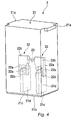
- an electric connection box 1 of the present invention has fuse cavities 11 formed in a plurality of portions of a face of a synthetic resin-made box body of the electric connection box 1, into which fuse cavities fuses can be inserted from the upper side, and has various electrical parts, various electric circuits and wiring, connecting these electrical parts, these electric circuits and the fuses, accommodated within the box body of the electric connection box 1.
- the electrical parts, the electric circuits and the wiring are not shown in Fig. 1 .
- the fuse cavity 11 is so formed that part or all of the fuse 2 can be accommodated in a recess portion formed by an inner bottom portion 11a and inner peripheral faces 11b of the fuse cavity 11.
- a pair of cavity terminals 12 project from the inner bottom portion 11a of the fuse cavity 11 (see Fig. 6 , etc.).
- the pair of cavity terminals 12 enter the inside of a housing 21 of the fuse 2, and come into contact respectively with a pair of fuse terminals 22 (see Fig. 4 , etc.) accommodated within the housing 21 of the fuse 2, and are electrically connected respectively to the fuse terminals.
- the fuse 2 is a slow blow fuse which is an anti-rush current-type fuse, and is constructed such that it comprises the pair of fuse terminals 22 made of a conductor, a fusible element 23 of an excellent anti-rush ability disposed between the pair of fuse terminals 22 and electrically connecting the pair of fuse terminals 22 together, and the synthetic resin-made housing 21 accommodating the fuse terminals 22 in a manner to cover the fusible element 23 and forming the outer shape of the fuse 2.
- the housing 21 is made of a colored transparent insulative synthetic resin material or the like. Since the housing 21 is formed of the transparent material, whether the fusible element 23 accommodated within the housing 21 is melted or not can be visually confirmed from the upper face, side faces and lower face of the housing 21. Engagement portions 21a are formed respectively at side portions of the upper end of the housing 21, and when the fuse 2 is inserted into the fuse cavity 11, the engagement portions 21a are fitted respectively into engagement grooves 17 formed in the fuse cavity 11. With respect to the fuse 2 inserted in the fuse cavity 11, its positioning in the downward direction in the fuse cavity 11 is effected also by the fitting of the engagement portions 21a into the respective engagement grooves 17 of the fuse cavity 11.
- open portions 21 c are formed in the lower face 21b of the housing 21, and also insertion passages 21d which the pair of cavity terminals 12 enter, respectively, are formed in the inside of the housing.
- Each of the fuse terminals 22 is a so-called tuning fork-like terminal which includes a pair of movable arm portions 22a capable of holding the cavity terminal 12, inserted in the insertion passage 21d, therebetween, a curved gripping portion 22b formed at a distal end of each movable arm portion 22a so as to positively contact the fuse terminal 22 with the cavity terminal 12, and a proximal end portion 22c from which the pair of movable arm portions 22a extend.
- the fuse terminal 22 is electrically connected to the cavity terminal 12 when the cavity terminal 12 inserted in the insertion passage 21d comes into contact with the gripping portions 22b of the fuse terminal 22.
- the fuse terminal 22 is the tuning fork-like terminal, it is not limited to the tuning fork-like terminal, and terminals of various shapes can be adopted (see, for example, Fig. 1 , Fig. 9 , of JP-A-8-185790 ).
- the fusible element 23 is formed of a material such as zinc, lead, silver or an alloy comprising them as a main component, and one end thereof is connected to the proximal end portion 22c of one fuse terminal 22, and the other end thereof is connected to the proximal end portion 22c of the other fuse terminal 22.
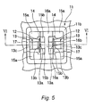
- the fuse cavity 11 is provided with the pair of cavity terminals 12 projecting from the inner bottom portion 11a of the fuse cavity 11, terminal support bodies 13 for fixing the respective cavity terminals 12, accommodating grooves 14 for respectively accommodating the lower ends of the cavity terminals 12 at a level below the inner bottom portion 11a, a non-projecting portion 15 forming part of the inner bottom portion 11a of the fuse cavity 11, a projecting portion 16 which forms part of the inner bottom portion 11a of the fuse cavity 11 and has an upper face disposed above the non-projecting portion 15, and the engagement grooves 17 for the fitting of the respective engagement portions 21a of the fuse 2 thereto when inserting the fuse 2 into the fuse cavity 11.
- the cavity terminal 12 is a so-called male tab terminal, and at the time when the fuse 2 is inserted into the fuse cavity 11, the cavity terminal 12 passes through the open portion 21c of the housing 21, and enters the insertion passage 21d of the housing 21, and is accommodated in the insertion passage 21d.
- the cavity terminal 12 inserted in the insertion passage 21d contacts the gripping portions 22b of the fuse terminal 22, and therefore is electrically connected to the fuse terminal 22.
- the fuse terminal 22 of the fuse 2 is the so-called tuning fork-like terminal
- the cavity terminal 12 of the fuse cavity 11 enters a tuning fork-like portion of the fuse terminal 22
- the constructions of the fuse terminal 22 and cavity terminal 12 may be reversed. Namely, there may be provided a construction in which the cavity terminal 12 is a so-called tuning fork-like terminal, while the fuse terminal 22 is a so-called male tab terminal.
- the terminal support body 13 includes a support projection 13a for passing through a hole, formed in the cavity terminal 12, to fix this cavity terminal 12, a holder 13b for holding the cavity terminal 12 through which the support projection 13a passes, and a support bar 13c which has the support projection 13a and the holder 13b extending from one end thereof and is fixed at the other end thereof to a box body of the fuse cavity 11.
- the support projection 13a is passed through the hole formed in the cavity terminal 12 until the cavity terminal 12 is brought into contact with the holder 13b, and by doing so, the cavity terminal 12 is fixed in such a manner that it projects from the inner bottom portion 11a of the fuse cavity 11.
- the non-projecting portion 15 forms part of the inner bottom portion 11a of the fuse cavity 11, and is formed by four corner portions 15a, defined by the inner peripheral faces 11b of the fuse cavity 11, and central portions 15b surrounded by the accommodating grooves 14, pedestals 16a as described later and an elongated projection 16b as described later.
- the projecting portion 16 forms part of the inner bottom portion 11a of the fuse cavity 11, and is formed by the two pedestals 16a, disposed contiguous respectively to two of the four inner peripheral faces 11b of the fuse cavity 11 which are opposed to each other in a direction perpendicular to the direction of juxtaposition of the pair of cavity terminals 12, and the elongated projection 16b having longitudinally-spaced opposite ends integrally molded respectively with the two pedestals 16a.
- the elongated projection 16b is provided to be located between the pair of cavity terminals 12, and is particularly so provided as to be located right beneath the fusible element 23 of the fuse 2 when the fuse 2 is inserted into the fuse cavity 11.
- the upper faces 16c of the pedestals 16a and the upper face 16d of the elongated projection 16b abut against the lower face 21b of the housing 21 of the fuse 2, while the upper faces 15c of the corner portions 15a and the upper faces 15d of the central portions 15b do not abut against the lower face 21b of the housing 21 of the fuse 2, and a gap 15e is formed between them and the lower face 21b of the housing 21 of the fuse 2. Therefore, the area of the lower face 21b of the housing 21 of the fuse 2 abutting against the inner bottom portion 11a of the fuse cavity 11 is limited to the areas of the faces defined by the upper faces 16c of the pedestals 16a and the upper face 16d of the elongated projection 16b.
- the engagement grooves 17 are provided respectively at those portions of the inner peripheral faces 11b spaced upwardly from the upper faces 16c of the pedestals 16a and the upper face 16d of the elongated projection by a length from the lower face 21b of the housing 21 of the fuse 2 to the engagement portions 21a.
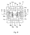
- the inner bottom portion 11a of the fuse cavity 11 shown in Fig. 8 , Fig. 9 and Fig. 10 is formed by four corner portions 11c defined by inner peripheral faces 11b of the fuse cavity 11, two pedestals 11d disposed contiguous respectively to two faces which are opposed to each other in a direction perpendicular to a direction of juxtaposition of a pair of cavity terminals 12, and an elongated projection 11e having longitudinally-spaced opposite ends integrally molded respectively with the two pedestals 16a.
- the inner bottom portion 11a of the fuse cavity 11 is not provided with the above-mentioned projecting portion 16, and an upper face 11f of the inner bottom portion 11a of the fuse cavity 11 formed by the corner portions 11c, the pedestals 11 d and the elongated projection 11e is formed on a common plane over an entire area thereof.
- the upper face 11f of the inner bottom portion 11a of the fuse cavity 11 is formed on the common plane, and therefore when the fuse 2 is inserted into the fuse cavity 11 as shown in Fig. 10 , the upper face 11f of the inner bottom portion 11a of the fuse cavity 11 abuts against the lower face 21b of the housing 21 of the fuse 2 over the entire area thereof. Therefore, the area of the lower face 21b of the housing 21 of the fuse 2 abutting against the inner bottom portion 11a of the fuse cavity 11 is larger as compared with the area of the lower face 21b of the housing 21 of the fuse 2 abutting against the inner bottom portion 11a of the fuse cavity 11.
- the area of the lower face 21b has been described with reference to Fig. 5 , Fig. 6 and Fig. 7 .
- the upper face of the projecting portion 16 formed on the inner bottom face of the fuse cavity 11 and extending upwardly from this inner bottom face abuts against the lower face 21b of the housing 21 of the fuse 2, and the gap 15e is formed between the inner bottom face of the fuse cavity 11 and the lower face 21b of the housing 21 of the fuse 2 because of the projecting portion 16.
- the elongated projection 16b of the projecting portion 16 is provided at the inner bottom portion 11a of the fuse cavity 11, and is located between the cavity terminals 12 when viewed from the upper side of the fuse cavity 11, and also is located right beneath the fusible element 23 of the fuse 2 inserted in the fuse cavity 11.
- the inner bottom portion 11a of the fuse cavity 11 has the projecting portion 16 formed on the inner bottom face thereof and extending upwardly from this inner bottom face
- a cubic structure having a bottom face defined by the upper face of the non-projecting portion 15 and a height defined by the height difference between the upper face of the non-projecting portion 15 and the upper face of the projecting portion 16, corresponds to the recess portions. Even in the construction in which the recess portions are provided at the inner bottom portion 11a of the fuse cavity 11, the area of that portion of the fuse cavity adhering to the fusedly-damaged portion of the housing can be kept to a small level in the same manner as in the construction in which the projecting portion 16 is provided at the inner bottom portion 11a of the fuse cavity 11.
- the position of the projecting portion 16 provided at the inner bottom portion 11a of the fuse cavity 11 is not limited to these positions, and can be provided at an arbitrary position of the inner bottom portion 11a of the fuse cavity 11.
- it is suitably provided taking the positions of the pair of cavity terminals 12, the positions of the terminal support bodies 13 and the positions of the accommodating grooves 14 into consideration.
- the inner bottom portion 11a of the fuse cavity 11 is formed by the non-projecting portion 18 and the projecting portion 19.
- the non-projecting portion 18 forms part of the inner bottom portion 11a of the fuse cavity 11, and is formed by two pedestals 18a, disposed contiguous respectively to two of four inner peripheral faces 11b of the fuse cavity 11 which are opposed to each other in a direction perpendicular to a direction of juxtaposition of a pair of cavity terminals 12, and an elongated projection 18b having longitudinally-spaced opposite ends integrally molded respectively with the two pedestals 18a.
- the projecting portion 19 is formed by four corner portions 19a defined by the four inner peripheral faces 11b of the fuse cavity 11.
- Upper faces 19b of the four corner portions 19a are formed on a common plane, and the positions of the upper faces 19b are disposed above upper faces 18c of the two pedestals 18a and an upper face 18d of the elongated projection 18b. Therefore, when the fuse 2 is inserted into the fuse cavity 11 as shown in Fig. 13 , the upper faces 19b of the four corner portions 19a abut against a lower face 21b of a housing 21 of the fuse 2, while the upper faces 18c of the two pedestals 18a and the upper face 18d of the elongated projection 18b do not abut against the lower face 21b of the housing 21 of the fuse 2, and a gap 18e is formed between them and the lower face 21b of the housing 21 of the fuse 2. Therefore, the area of the lower face 21b of the housing 21 of the fuse 2 abutting against the inner bottom portion 11a of the fuse cavity 11 is limited to the areas of the upper faces 19b of the four corner portions 19a.
- the four corner portions 19 are formed in a projecting manner on the inner bottom portion 11a so that the gap 18e can be formed between the upper faces 18c of the pedestals 18a or the upper face 18d of the elongated projection 18b and the lower face 21b of the housing 21 of the fuse 2.
- the fusedly-damaged housing can even be prevented from adhering to the upper faces of the projecting portion 16.
- the electric connection box of the present invention even when that portion of the housing of the fuse disposed forwardly in the direction of insertion into the fuse cavity is fusedly damaged by heat radiation of the fusible element or the deposition of the melted fusible element, the area of that portion of the fuse cavity adhering to the fusedly-damaged portion of the housing can be kept to a small level. Therefore, the fuse whose housing is fusedly-damaged can be easily taken out from the fuse cavity. Therefore, in the present invention, a workload for fuse exchange can be reduced.
- the fusedly-damaged housing when the slow blow fuse whose housing can be more fusedly damaged is inserted, the fusedly-damaged housing can be more markedly restrained from adhering to the inner bottom face of the fuse cavity.
- the area of the portion of the fuse cavity adhering to the fusedly-damaged portion of the housing can be kept to a small level, and therefore the fuse whose housing is fusedly damaged can be easily taken out from the fuse cavity, and therefore the workload for fuse exchange can be reduced.
Landscapes
- Engineering & Computer Science (AREA)
- Architecture (AREA)
- Civil Engineering (AREA)
- Structural Engineering (AREA)
- Fuses (AREA)
- Connection Or Junction Boxes (AREA)
Abstract
Description
- The present invention is related to an electric connection box having fuse cavities for accommodating fuses.
- As a conventional electric connection box having fuse cavities, an electric connection box disclosed in
PLT 1 is cited.Fig. 14 is a perspective view showing a main portion of the conventional electric connection box in a fuse non-attached condition.Fig. 15 is a perspective showing a condition in which a fuse is attached to the electric connection box ofFig. 14 . - The conventional
electric connection box 5 shown inFig. 14 has afuse cavity 51 into which thefuse 6 can be inserted from the upper side. A pair ofcavity terminals 52 project from an inner bottom face of thefuse cavity 51. When thefuse 6 shown inFig. 15 is inserted into thefuse cavity 51, a pair of fuse terminals (not shown inFig. 14 andFig. 15 ) accommodated in ahousing 61 of thefuse 6 come into contact with the pair ofcavity terminals 52 and are electrically connected thereto.
Citation List
Patent Literature
[PLT 1]JP-A-2004-64871 - However, in the conventional
electric connection box 5, in a case where thehousing 61 is fusedly damaged by heat radiation of a fusible element (not shown inFig. 14 andFig. 15 ) of thefuse 6 or by deposition of the melted fusible element, a lower face of thehousing 61 adheres to the inner bottom face of thefuse cavity 51. The lower face is a portion of thehousing 61 disposed forwardly in a direction of insertion into thefuse cavity 51. As a result, it is difficult to withdraw thefuse 6, having the fusedly-damagedhousing 61, from theelectric connection box 5. - The above-mentioned matter is more liable to occur particularly in the case where the
fuse 6 is a slow blow fuse, which is an anti-rush current-type fuse, than in the case where it is a quick blow-type fuse. The reason for this is that the blowing time of the slow blow fuse lasts long, so that thehousing 61 forming the slow blow fuse is more fusedly damaged. - The present invention has been made in view of the above circumstances, and its object is to provide an electric connection box in which even when a housing of a fuse is fusedly damaged by heat radiation or melting of a fusible element of the fuse, the fusedly-damaged housing can be restrained from adhering to an inner bottom portion of a fuse cavity.
-
- (1) In order to achieve the above-mentioned object, an electric connection box of the present invention comprises:
- a fuse cavity, made of synthetic resin, into which a fuse can be inserted from an upper side, the fuse including a pair of fuse terminals, a fusible element electrically connecting the fuse terminals, and a housing made of synthetic resin and accommodating the fuse terminals so as to cover the fusible element; and
- a pair of cavity terminals configured to come in contact with the fuse terminals to be electrically connected thereto when the fuse is inserted into the fuse cavity,
- wherein a lower face of the housing of the fuse inserted in the fuse cavity is configured to abut against an inner bottom portion of the fuse cavity, so that the fuse is positioned in the fuse cavity in a downward direction;
- wherein the inner bottom portion has a projecting portion formed on an inner bottom face of the inner bottom portion and extending upwardly from the inner bottom face;
- wherein an upper face of the projecting portion abuts against the lower face of the housing; and
- wherein a gap is formed between the inner bottom face and the lower face of the housing by the projecting portion..
- In the electric connection box of the present invention, described as (1), the upper face of the projecting portion, formed on the inner bottom face of the fuse cavity and extending upwardly from the inner bottom face, abuts against the lower face of the housing of the fuse, and the gap is formed between the inner bottom face of the fuse cavity and the lower face of the housing of the fuse because of the projecting portion. Therefore, even when that portion of the housing of the fuse disposed forwardly in the direction of insertion into the fuse cavity which is a wall portion forming the lower face of the housing of the fuse is fusedly damaged by heat radiation of the fusible element or the deposition of the melted fusible element, the area of that portion of the fuse cavity adhering to the fusedly-damaged portion of the housing can be kept to a small level. Therefore, the fuse whose housing is fusedly-damaged can be easily taken out from the fuse cavity.
-
- (2) Furthermore, it is preferred that the projecting portion is provided at the inner bottom face between the cavity terminals when the fuse cavity is viewed from the upper side, and the projecting portion is located right beneath the fusible element of the fuse accommodated in the fuse cavity.
- With the construction described as (2), when the fuse is accommodated in the electric connection box, the housing of the fuse is supported in a well-balanced manner in a stable condition thanks to the cooperation of the upper face of the projecting portion and an inner peripheral face of the fuse cavity with each other, and therefore this is preferable.
-
- (3) Furthermore, it is preferred that the projecting portion is projected on the inner bottom face so that the gap is formed between a lower face of a portion of the housing of the fuse located right beneath the fusible element and the inner bottom face of the fuse cavity, in a state where the fuse is accommodated in the fuse cavity.
- With the construction described as (3), the projecting portion is provided avoiding the region right beneath the fusible element of the fuse, and namely when by heat radiation of the fusible element or the deposition of the melted fusible element, the housing of the fuse is fusedly damaged starting from the portion thereof near to the fusible element which portion is liable to be fusedly damaged, the upper face of the projecting portion abuts against that portion which is, the portion harder to fusedly damage of the lower face of the housing of the fuse disposed farther away from the fusible element, and therefore the fusedly-damaged housing can even be prevented from adhering to the upper face of the projecting portion, and therefore this is preferable. As a result of thus restraining the fusedly-damaged housing from adhering to the inner bottom portion of the fuse cavity, the fuse whose housing is fusedly damaged can be easily taken out from the electric connection box.
-
- (4) It is preferred that the fuse of the electric connection box as described above is a slow blow fuse.
- With the construction described as (4), when the slow blow fuse whose housing tends to be more fusedly damaged is accommodated, the fusedly-damaged housing can be more markedly restrained from adhering to the inner bottom portion of the fuse cavity, and therefore this is preferable.
- In the electric connection box of the present invention, even when the housing of the fuse is fusedly damaged by heat radiation or melting of the fusible element of the fuse, the fusedly-damaged housing can be restrained from adhering to the inner bottom portion of the fuse cavity, and therefore the fuse whose housing is fusedly damaged can be easily taken out from the electric connection box. Therefore, in the present invention, a workload for fuse exchange can be reduced.
-
-
Fig. 1 is a perspective view of one embodiment of an electric connection box of the present invention. -
Fig. 2 is a perspective view showing an main portion of the one embodiment of the electric connection box of the present invention in a fuse non-attached condition. -
Fig. 3 is a perspective view showing a condition in which a fuse is attached to the electric connection box shown inFig. 2 . -
Fig. 4 is a perspective view of the fuse to be inserted into the one embodiment of the electric connection box of the present invention. -
Fig. 5 is a view showing a fuse cavity of the one embodiment of the electric connection box of the present invention as seen from an upper side. -
Fig. 6 is a cross-sectional view taken along the line VI-VI ofFig. 5 . -
Fig. 7 is a cross-sectional view showing a condition in which the fuse is attached to the fuse cavity ofFig. 6 . -
Fig. 8 is a view showing a fuse cavity of an electric connection box which is not provided with a projecting portion, as seen from an upper side. -
Fig. 9 is a cross-sectional view taken along the line IX-IX ofFig. 8 . -
Fig. 10 is a cross-sectional view showing a condition in which a fuse is attached to the fuse cavity ofFig. 9 . -
Fig. 11 is a view showing a fuse cavity of another embodiment of an electric connection box of the present invention as seen from an upper side. -
Fig. 12 is a cross-sectional view taken along the line XII-XII ofFig. 11 . -
Fig. 13 is a cross-sectional view showing a condition in which a fuse is attached to the fuse cavity ofFig. 12 . -
Fig. 14 is a perspective view showing an main portion of one form of conventional electric connector in a fuse non-attached condition. -
Fig. 15 is a perspective view showing a condition in which a fuse is attached to the electric connection box ofFig. 14 . - Preferred embodiments of the present invention will be described below in detail with reference to the drawings.
- As shown in
Fig. 1 , one embodiment of anelectric connection box 1 of the present invention hasfuse cavities 11 formed in a plurality of portions of a face of a synthetic resin-made box body of theelectric connection box 1, into which fuse cavities fuses can be inserted from the upper side, and has various electrical parts, various electric circuits and wiring, connecting these electrical parts, these electric circuits and the fuses, accommodated within the box body of theelectric connection box 1. The electrical parts, the electric circuits and the wiring are not shown inFig. 1 . - As shown in
Fig. 2 and Fig. 3 , thefuse cavity 11 is so formed that part or all of thefuse 2 can be accommodated in a recess portion formed by aninner bottom portion 11a and innerperipheral faces 11b of thefuse cavity 11. A pair ofcavity terminals 12 project from theinner bottom portion 11a of the fuse cavity 11 (seeFig. 6 , etc.). At the time when thefuse 2 is inserted into thefuse cavity 11, the pair ofcavity terminals 12 enter the inside of ahousing 21 of thefuse 2, and come into contact respectively with a pair of fuse terminals 22 (seeFig. 4 , etc.) accommodated within thehousing 21 of thefuse 2, and are electrically connected respectively to the fuse terminals. With respect to thefuse 2 inserted in thefuse cavity 11, its positioning in a downward direction in thefuse cavity 11 is effected by the abutting of a lower face of thehousing 21 of thefuse 2 against theinner bottom portion 11a of the fuse cavity. A specific construction with which the lower face of thehousing 21 of thefuse 2 abuts against theinner bottom portion 11a of thefuse cavity 11 will be described later. - Next, the structure of the
fuse 2 to be inserted into the one embodiment of the electric connection box of the present invention will be described in detail. As shown inFig. 4 , thefuse 2 is a slow blow fuse which is an anti-rush current-type fuse, and is constructed such that it comprises the pair offuse terminals 22 made of a conductor, afusible element 23 of an excellent anti-rush ability disposed between the pair offuse terminals 22 and electrically connecting the pair offuse terminals 22 together, and the synthetic resin-madehousing 21 accommodating thefuse terminals 22 in a manner to cover thefusible element 23 and forming the outer shape of thefuse 2. - The
housing 21 is made of a colored transparent insulative synthetic resin material or the like. Since thehousing 21 is formed of the transparent material, whether thefusible element 23 accommodated within thehousing 21 is melted or not can be visually confirmed from the upper face, side faces and lower face of thehousing 21.Engagement portions 21a are formed respectively at side portions of the upper end of thehousing 21, and when thefuse 2 is inserted into thefuse cavity 11, theengagement portions 21a are fitted respectively intoengagement grooves 17 formed in thefuse cavity 11. With respect to thefuse 2 inserted in thefuse cavity 11, its positioning in the downward direction in thefuse cavity 11 is effected also by the fitting of theengagement portions 21a into therespective engagement grooves 17 of thefuse cavity 11. In order to guide the pair ofcavity terminals 12 into the inside of thehousing 21 at the time when thefuse 2 is inserted into thefuse cavity 11,open portions 21 c are formed in thelower face 21b of thehousing 21, and alsoinsertion passages 21d which the pair ofcavity terminals 12 enter, respectively, are formed in the inside of the housing. - Each of the
fuse terminals 22 is a so-called tuning fork-like terminal which includes a pair ofmovable arm portions 22a capable of holding thecavity terminal 12, inserted in theinsertion passage 21d, therebetween, a curvedgripping portion 22b formed at a distal end of eachmovable arm portion 22a so as to positively contact thefuse terminal 22 with thecavity terminal 12, and aproximal end portion 22c from which the pair ofmovable arm portions 22a extend. Thefuse terminal 22 is electrically connected to thecavity terminal 12 when thecavity terminal 12 inserted in theinsertion passage 21d comes into contact with the grippingportions 22b of thefuse terminal 22. Incidentally, in the one embodiment of the present invention, although thefuse terminal 22 is the tuning fork-like terminal, it is not limited to the tuning fork-like terminal, and terminals of various shapes can be adopted (see, for example,Fig. 1 ,Fig. 9 , ofJP-A-8-185790 - The
fusible element 23 is formed of a material such as zinc, lead, silver or an alloy comprising them as a main component, and one end thereof is connected to theproximal end portion 22c of onefuse terminal 22, and the other end thereof is connected to theproximal end portion 22c of theother fuse terminal 22. - Next, the structure of the
fuse cavity 11 in the one embodiment of the electric connection box of the present invention will be described in detail. As shown inFig. 5 andFig. 6 , thefuse cavity 11 is provided with the pair ofcavity terminals 12 projecting from theinner bottom portion 11a of thefuse cavity 11,terminal support bodies 13 for fixing therespective cavity terminals 12, accommodatinggrooves 14 for respectively accommodating the lower ends of thecavity terminals 12 at a level below theinner bottom portion 11a, anon-projecting portion 15 forming part of theinner bottom portion 11a of thefuse cavity 11, a projectingportion 16 which forms part of theinner bottom portion 11a of thefuse cavity 11 and has an upper face disposed above thenon-projecting portion 15, and theengagement grooves 17 for the fitting of therespective engagement portions 21a of thefuse 2 thereto when inserting thefuse 2 into thefuse cavity 11. - The
cavity terminal 12 is a so-called male tab terminal, and at the time when thefuse 2 is inserted into thefuse cavity 11, thecavity terminal 12 passes through theopen portion 21c of thehousing 21, and enters theinsertion passage 21d of thehousing 21, and is accommodated in theinsertion passage 21d. Thecavity terminal 12 inserted in theinsertion passage 21d contacts thegripping portions 22b of thefuse terminal 22, and therefore is electrically connected to thefuse terminal 22. Incidentally, in the one embodiment of the present invention, description is made of the construction in which thefuse terminal 22 of thefuse 2 is the so-called tuning fork-like terminal, and thecavity terminal 12 of thefuse cavity 11 enters a tuning fork-like portion of thefuse terminal 22; however, the constructions of thefuse terminal 22 andcavity terminal 12 may be reversed. Namely, there may be provided a construction in which thecavity terminal 12 is a so-called tuning fork-like terminal, while thefuse terminal 22 is a so-called male tab terminal. - The
terminal support body 13 includes asupport projection 13a for passing through a hole, formed in thecavity terminal 12, to fix thiscavity terminal 12, aholder 13b for holding thecavity terminal 12 through which thesupport projection 13a passes, and asupport bar 13c which has thesupport projection 13a and theholder 13b extending from one end thereof and is fixed at the other end thereof to a box body of thefuse cavity 11. At the time when the lower end of thecavity terminal 12 is accommodated in theaccommodating groove 14, thesupport projection 13a is passed through the hole formed in thecavity terminal 12 until thecavity terminal 12 is brought into contact with theholder 13b, and by doing so, thecavity terminal 12 is fixed in such a manner that it projects from theinner bottom portion 11a of thefuse cavity 11. - The
non-projecting portion 15 forms part of theinner bottom portion 11a of thefuse cavity 11, and is formed by fourcorner portions 15a, defined by the inner peripheral faces 11b of thefuse cavity 11, andcentral portions 15b surrounded by theaccommodating grooves 14, pedestals 16a as described later and anelongated projection 16b as described later. - The projecting
portion 16 forms part of theinner bottom portion 11a of thefuse cavity 11, and is formed by the twopedestals 16a, disposed contiguous respectively to two of the four inner peripheral faces 11b of thefuse cavity 11 which are opposed to each other in a direction perpendicular to the direction of juxtaposition of the pair ofcavity terminals 12, and theelongated projection 16b having longitudinally-spaced opposite ends integrally molded respectively with the twopedestals 16a. Theelongated projection 16b is provided to be located between the pair ofcavity terminals 12, and is particularly so provided as to be located right beneath thefusible element 23 of thefuse 2 when thefuse 2 is inserted into thefuse cavity 11. Upper faces 16c of thepedestals 16a and anupper face 16d of theelongated projection 16b are formed on a common plane, and the positions of these upper faces are disposed aboveupper faces 15c of thecorner portions 15a andupper faces 15d of thecentral portions 15b which form thenon-projecting portion 15. Therefore, when thefuse 2 is inserted into thefuse cavity 11 as shown inFig. 7 , the upper faces 16c of thepedestals 16a and theupper face 16d of theelongated projection 16b abut against thelower face 21b of thehousing 21 of thefuse 2, while the upper faces 15c of thecorner portions 15a and the upper faces 15d of thecentral portions 15b do not abut against thelower face 21b of thehousing 21 of thefuse 2, and agap 15e is formed between them and thelower face 21b of thehousing 21 of thefuse 2. Therefore, the area of thelower face 21b of thehousing 21 of thefuse 2 abutting against theinner bottom portion 11a of thefuse cavity 11 is limited to the areas of the faces defined by the upper faces 16c of thepedestals 16a and theupper face 16d of theelongated projection 16b. - Taking it into consideration that the upper faces 16c of the
pedestals 16a and theupper face 16d of theelongated projection 16b abut against thelower face 21b of thehousing 21 of the fuse when thefuse 2 is inserted into thefuse cavity 11, theengagement grooves 17 are provided respectively at those portions of the inner peripheral faces 11b spaced upwardly from the upper faces 16c of thepedestals 16a and theupper face 16d of the elongated projection by a length from thelower face 21b of thehousing 21 of thefuse 2 to theengagement portions 21a. With this arrangement, even when the upper faces 16c of thepedestals 16a and theupper face 16d of theelongated projection 16b abut against thelower face 21b of thehousing 21 of the fuse, theengagement portions 21a of thefuse 2 are fitted respectively into theengagement grooves 17 of thefuse cavity 11. - Next, in order to compare the area of the
inner bottom portion 11a of the fuse cavity 11 (which has been described with reference toFig. 5 ,Fig. 6 andFig. 7 ) which abuts against thelower face 21b of thehousing 21 of thefuse 2, the structure of a fuse cavity which is not provided with a projecting portion will be described as a reference example with reference toFig. 8 to Fig. 10 . Each portion of thefuse cavity 11 except aninner bottom portion 11a and each portion of afuse 2 are as described with reference toFig. 4 to Fig. 7 , and explanation thereof will be omitted. - The
inner bottom portion 11a of thefuse cavity 11 shown inFig. 8 ,Fig. 9 andFig. 10 is formed by fourcorner portions 11c defined by inner peripheral faces 11b of thefuse cavity 11, twopedestals 11d disposed contiguous respectively to two faces which are opposed to each other in a direction perpendicular to a direction of juxtaposition of a pair ofcavity terminals 12, and anelongated projection 11e having longitudinally-spaced opposite ends integrally molded respectively with the twopedestals 16a. Theinner bottom portion 11a of thefuse cavity 11 is not provided with the above-mentioned projectingportion 16, and anupper face 11f of theinner bottom portion 11a of thefuse cavity 11 formed by thecorner portions 11c, thepedestals 11 d and theelongated projection 11e is formed on a common plane over an entire area thereof. - The
upper face 11f of theinner bottom portion 11a of thefuse cavity 11 is formed on the common plane, and therefore when thefuse 2 is inserted into thefuse cavity 11 as shown inFig. 10 , theupper face 11f of theinner bottom portion 11a of thefuse cavity 11 abuts against thelower face 21b of thehousing 21 of thefuse 2 over the entire area thereof. Therefore, the area of thelower face 21b of thehousing 21 of thefuse 2 abutting against theinner bottom portion 11a of thefuse cavity 11 is larger as compared with the area of thelower face 21b of thehousing 21 of thefuse 2 abutting against theinner bottom portion 11a of thefuse cavity 11. The area of thelower face 21b has been described with reference toFig. 5 ,Fig. 6 andFig. 7 . - As described above, in the
fuse cavity 11 of the electric connection box according to the one embodiment of the present invention, the upper face of the projectingportion 16 formed on the inner bottom face of thefuse cavity 11 and extending upwardly from this inner bottom face abuts against thelower face 21b of thehousing 21 of thefuse 2, and thegap 15e is formed between the inner bottom face of thefuse cavity 11 and thelower face 21b of thehousing 21 of thefuse 2 because of the projectingportion 16. Therefore, even when that portion of the housing of the fuse disposed forwardly in the direction of insertion into the fuse cavity is fusedly damaged by heat radiation of the fusible element or the deposition of the melted fusible element, the area of that portion of the fuse cavity adhering to the fusedly-damaged portion of the housing can be kept to a small level. Therefore, the fuse whose housing is fusedly-damaged can be easily taken out from the fuse cavity. - Furthermore, in the
fuse cavity 11 of the electric connection box according to the one embodiment of the present invention, theelongated projection 16b of the projectingportion 16 is provided at theinner bottom portion 11a of thefuse cavity 11, and is located between thecavity terminals 12 when viewed from the upper side of thefuse cavity 11, and also is located right beneath thefusible element 23 of thefuse 2 inserted in thefuse cavity 11. By the cooperation of theupper face 16d of thiselongated projection 16b and the inner peripheral faces 11b of the fuse cavity with each other, the well-balanced stable supporting of thehousing 21 of thefuse 2 can be effected when thefuse 2 is accommodated within theelectric connection box 1. - In the one embodiment of the electric connection box of the present invention, although description has been made of the construction in which the
inner bottom portion 11a of thefuse cavity 11 has the projectingportion 16 formed on the inner bottom face thereof and extending upwardly from this inner bottom face, there may be provided a construction in which theinner bottom portion 11a of thefuse cavity 11 has recess portions formed at the inner bottom face thereof and recessed downwardly from this inner bottom face. When applying this construction to theinner bottom portion 11a of thefuse cavity 11 which has been described with reference toFig. 5 ,Fig. 6 andFig. 7 , a cubic structure, having a bottom face defined by the upper face of thenon-projecting portion 15 and a height defined by the height difference between the upper face of thenon-projecting portion 15 and the upper face of the projectingportion 16, corresponds to the recess portions. Even in the construction in which the recess portions are provided at theinner bottom portion 11a of thefuse cavity 11, the area of that portion of the fuse cavity adhering to the fusedly-damaged portion of the housing can be kept to a small level in the same manner as in the construction in which the projectingportion 16 is provided at theinner bottom portion 11a of thefuse cavity 11. - In the above-mentioned one embodiment of the electric connection box of the present invention, although description has been made of the construction in which the
pedestals 16a which are part of the projectingportion 16 are provided to be disposed contiguous to the inner peripheral faces 11 of thefuse cavity 11, and theelongated projection 16b which is part of the projectingportion 16 is provided to be located between the pair ofcavity terminals 12, the position of the projectingportion 16 provided at theinner bottom portion 11a of thefuse cavity 11 is not limited to these positions, and can be provided at an arbitrary position of theinner bottom portion 11a of thefuse cavity 11. Preferably, it is suitably provided taking the positions of the pair ofcavity terminals 12, the positions of theterminal support bodies 13 and the positions of theaccommodating grooves 14 into consideration. - The case where a projecting portion is provided at a position different from that in the above-mentioned one embodiment of the electric connection box of the present invention will be described with reference to
Fig. 11 to Fig. 13 . Here, each portion of afuse cavity 11 forming aninner bottom portion 11a except a non-projecting portion and the projecting portion as well as each portion of thefuse 2 is as described with reference toFig. 4 to Fig. 7 , and therefore explanation thereof will be omitted. - The
inner bottom portion 11a of thefuse cavity 11 is formed by thenon-projecting portion 18 and the projectingportion 19. Thenon-projecting portion 18 forms part of theinner bottom portion 11a of thefuse cavity 11, and is formed by twopedestals 18a, disposed contiguous respectively to two of four inner peripheral faces 11b of thefuse cavity 11 which are opposed to each other in a direction perpendicular to a direction of juxtaposition of a pair ofcavity terminals 12, and anelongated projection 18b having longitudinally-spaced opposite ends integrally molded respectively with the twopedestals 18a. The projectingportion 19 is formed by fourcorner portions 19a defined by the four inner peripheral faces 11b of thefuse cavity 11. Upper faces 19b of the fourcorner portions 19a are formed on a common plane, and the positions of the upper faces 19b are disposed aboveupper faces 18c of the twopedestals 18a and anupper face 18d of theelongated projection 18b. Therefore, when thefuse 2 is inserted into thefuse cavity 11 as shown inFig. 13 , the upper faces 19b of the fourcorner portions 19a abut against alower face 21b of ahousing 21 of thefuse 2, while the upper faces 18c of the twopedestals 18a and theupper face 18d of theelongated projection 18b do not abut against thelower face 21b of thehousing 21 of thefuse 2, and a gap 18e is formed between them and thelower face 21b of thehousing 21 of thefuse 2. Therefore, the area of thelower face 21b of thehousing 21 of thefuse 2 abutting against theinner bottom portion 11a of thefuse cavity 11 is limited to the areas of the upper faces 19b of the fourcorner portions 19a. - As described above, in the
fuse cavity 11 of the electric connection box according to the other embodiment of the present invention, the fourcorner portions 19 are formed in a projecting manner on theinner bottom portion 11a so that the gap 18e can be formed between theupper faces 18c of thepedestals 18a or theupper face 18d of theelongated projection 18b and thelower face 21b of thehousing 21 of thefuse 2. When thehousing 21 of thefuse 2 is fusedly damaged, the fusing damage starts from the portion near to afusible element 23; however, when thefuse cavity 11 having thefuse 2 inserted therein is viewed from the upper side, the fourcorner portions 19a are located at the respective regions disposed far away from thefusible element 23, and therefore the upper faces of the projectingportion 19 abut respectively against those portions of thelower face 21b of thehousing 21 which are harder to fusedly damage. Therefore, the fusedly-damaged housing can even be prevented from adhering to the upper faces of the projectingportion 16. - As described above, in the electric connection box of the present invention, even when that portion of the housing of the fuse disposed forwardly in the direction of insertion into the fuse cavity is fusedly damaged by heat radiation of the fusible element or the deposition of the melted fusible element, the area of that portion of the fuse cavity adhering to the fusedly-damaged portion of the housing can be kept to a small level. Therefore, the fuse whose housing is fusedly-damaged can be easily taken out from the fuse cavity. Therefore, in the present invention, a workload for fuse exchange can be reduced.
- In the electric connection box of the present invention, when the slow blow fuse whose housing can be more fusedly damaged is inserted, the fusedly-damaged housing can be more markedly restrained from adhering to the inner bottom face of the fuse cavity.
- The present Application is based on Japanese Patent Application No.
2008-013063 filed on January 23, 2008 - In the electric connection box of the present invention, the area of the portion of the fuse cavity adhering to the fusedly-damaged portion of the housing can be kept to a small level, and therefore the fuse whose housing is fusedly damaged can be easily taken out from the fuse cavity, and therefore the workload for fuse exchange can be reduced.
-
- 1
- electric connection box
- 11
- fuse cavity
- 11a
- inner bottom portion of the fuse cavity
- 12
- cavity terminal
- 13
- terminal support body
- 14
- accommodating groove
- 15
- non-projecting portion
- 15a
- corner portion
- 15b
- central portion
- 15c
- upper face of the
corner portion 15a - 15d
- upper face of the
central portion 15b - 15e
- gap
- 16
- projecting portion
- 16a
- pedestal
- 16b
- elongated projection
- 16c
- upper face of the
pedestal 16a - 16d
- upper face of the
elongated projection 16b - 17
- engagement groove
- 2
- fuse
- 21
- housing
- 21a
- engagement portion
- 21b
- lower face of the
housing 21 - 21c
- open portion
- 21d
- insertion passage
- 22
- fuse terminal
- 23
- fusible element
Claims (6)
- An electric connection box comprising:a fuse cavity, made of synthetic resin, into which a fuse can be inserted from an upper side, the fuse including a pair of fuse terminals, a fusible element electrically connecting the fuse terminals, and a housing made of synthetic resin and accommodating the fuse terminals so as to cover the fusible element; anda pair of cavity terminals configured to come in contact with the fuse terminals to be electrically connected thereto when the fuse is inserted into the fuse cavity,wherein a lower face of the housing of the fuse inserted in the fuse cavity is configured to abut against an inner bottom portion of the fuse cavity, so that the fuse is positioned in the fuse cavity in a downward direction;wherein the inner bottom portion has a projecting portion formed on an inner bottom face of the inner bottom portion and extending upwardly from the inner bottom face;wherein an upper face of the projecting portion abuts against the lower face of the housing; andwherein a gap is formed between the inner bottom face and the lower face of the housing by the projecting portion.
- An electric connection box as set forth in claim 1, wherein
the projecting portion is provided at the inner bottom face between the cavity terminals when the fuse cavity is viewed from the upper side, and
the projecting portion is located right beneath the fusible element of the fuse accommodated in the fuse cavity. - An electric connection box as set forth in claim 1, wherein
the projecting portion is projected on the inner bottom face so that the gap is formed between a lower face of a portion of the housing of the fuse located right beneath the fusible element and the inner bottom face of the fuse cavity, in a state where the fuse is accommodated in the fuse cavity. - An electric connection box as set forth in claim 1, wherein the fuse is a slow blow fuse.
- An electric connection box as set forth in claim 2, wherein the fuse is a slow blow fuse.
- An electric connection box as set forth in claim 3, wherein the fuse is a slow blow fuse.
Applications Claiming Priority (2)
| Application Number | Priority Date | Filing Date | Title |
|---|---|---|---|
| JP2008013063A JP5187941B2 (en) | 2008-01-23 | 2008-01-23 | Electrical junction box |
| PCT/JP2009/050885 WO2009093613A1 (en) | 2008-01-23 | 2009-01-21 | Electric connection box |
Publications (3)
| Publication Number | Publication Date |
|---|---|
| EP2242157A1 true EP2242157A1 (en) | 2010-10-20 |
| EP2242157A4 EP2242157A4 (en) | 2014-04-30 |
| EP2242157B1 EP2242157B1 (en) | 2018-11-28 |
Family
ID=40901121
Family Applications (1)
| Application Number | Title | Priority Date | Filing Date |
|---|---|---|---|
| EP09703687.5A Active EP2242157B1 (en) | 2008-01-23 | 2009-01-21 | Electric connection box |
Country Status (5)
| Country | Link |
|---|---|
| US (1) | US8339236B2 (en) |
| EP (1) | EP2242157B1 (en) |
| JP (1) | JP5187941B2 (en) |
| CN (1) | CN101926066B (en) |
| WO (1) | WO2009093613A1 (en) |
Cited By (1)
| Publication number | Priority date | Publication date | Assignee | Title |
|---|---|---|---|---|
| GB2486612A (en) * | 2012-03-23 | 2012-06-20 | Lucy & Company Ltd W | Fuse holder |
Families Citing this family (5)
| Publication number | Priority date | Publication date | Assignee | Title |
|---|---|---|---|---|
| KR20140107242A (en) * | 2011-12-13 | 2014-09-04 | 볼보 컨스트럭션 이큅먼트 에이비 | System for prevention of and protection against fire due to fuse misuse |
| US8961197B2 (en) | 2012-06-08 | 2015-02-24 | Lear Corporation | Fuse housing assembly |
| JP6601330B2 (en) * | 2016-07-01 | 2019-11-06 | 住友電装株式会社 | Electrical junction box with intermittent structure of dark current circuit |
| CN110224368A (en) * | 2019-07-04 | 2019-09-10 | 淮南常力达电气有限公司 | A kind of high voltage cable branch box of radiating explosion-proof |
| KR20210139001A (en) * | 2020-05-13 | 2021-11-22 | 주식회사 엘지에너지솔루션 | Battery Pack With Fuse-Box Bracket of Preventing Short Circuit |
Citations (1)
| Publication number | Priority date | Publication date | Assignee | Title |
|---|---|---|---|---|
| JP2004064871A (en) * | 2002-07-29 | 2004-02-26 | Furukawa Electric Co Ltd:The | Electrical connection box |
Family Cites Families (33)
| Publication number | Priority date | Publication date | Assignee | Title |
|---|---|---|---|---|
| US4670729A (en) * | 1986-06-03 | 1987-06-02 | Littelfuse, Inc. | Electrical fuse |
| JPH01150250U (en) | 1988-04-11 | 1989-10-17 | ||
| JPH0731486Y2 (en) * | 1989-12-28 | 1995-07-19 | 矢崎総業株式会社 | Cassette fuse junction box |
| JP2563313Y2 (en) * | 1990-08-06 | 1998-02-18 | 矢崎総業株式会社 | Electrical junction box |
| JP2563311Y2 (en) * | 1990-09-12 | 1998-02-18 | 矢崎総業株式会社 | Fuse box |
| US5171293A (en) * | 1991-12-05 | 1992-12-15 | Yazaki Corporation | Fuse box assembly |
| JP2634524B2 (en) * | 1991-12-06 | 1997-07-30 | 矢崎総業株式会社 | Intermittent mechanism of dark current fuse |
| JP2879811B2 (en) * | 1993-07-02 | 1999-04-05 | 矢崎総業株式会社 | Intermittent mechanism of dark current fuse and electric junction box provided with the same |
| JP3083059B2 (en) | 1994-12-28 | 2000-09-04 | 矢崎総業株式会社 | Fusible link |
| JP3083061B2 (en) * | 1995-01-20 | 2000-09-04 | 矢崎総業株式会社 | Fuse connection structure |
| US5662496A (en) * | 1995-06-07 | 1997-09-02 | Yazaki Corporation | Fuse junction box |
| JPH09171765A (en) * | 1995-12-20 | 1997-06-30 | Yazaki Corp | Fuse box |
| JP3216791B2 (en) * | 1996-05-24 | 2001-10-09 | 矢崎総業株式会社 | Drainage structure of electronic unit box |
| US6089918A (en) * | 1997-06-30 | 2000-07-18 | Yazaki Corporation | Adapter for electrical circuit components |
| US5886612A (en) * | 1997-10-20 | 1999-03-23 | Littelfuse, Inc. | Female fuse housing |
| JP2001250466A (en) * | 2000-03-03 | 2001-09-14 | Taiheiyo Seiko Kk | Fuse element and fuse mounting device |
| JP3242095B2 (en) * | 2000-05-16 | 2001-12-25 | 矢崎総業株式会社 | fuse |
| JP3722421B2 (en) | 2001-04-06 | 2005-11-30 | 矢崎総業株式会社 | Fuse box |
| GB2385723B (en) * | 2002-02-21 | 2004-07-07 | Yazaki Corp | Fuse and fuse production method |
| US6922332B2 (en) * | 2002-04-10 | 2005-07-26 | Furukawa Electric Co., Ltd. | Electric connection box |
| JP2003339109A (en) * | 2002-05-20 | 2003-11-28 | Yazaki Corp | Terminal-supporting hole structure |
| JP4047073B2 (en) * | 2002-05-31 | 2008-02-13 | 矢崎総業株式会社 | Electrical junction box cavity structure |
| JP2004032839A (en) * | 2002-06-21 | 2004-01-29 | Sumitomo Wiring Syst Ltd | Electric junction box |
| EP1611653B1 (en) * | 2003-04-04 | 2008-06-25 | Yazaki Corporation | Fuse cavity structure and electric connection box |
| US7077667B2 (en) * | 2003-04-22 | 2006-07-18 | Yazaki Corporation | Electrical junction box |
| US6781503B1 (en) * | 2003-04-24 | 2004-08-24 | Yazaki Corporation | Fuse assembly for differently structured fuses |
| JP4098680B2 (en) * | 2003-07-31 | 2008-06-11 | 矢崎総業株式会社 | Fuse cavity and electrical junction box |
| JP2005209509A (en) * | 2004-01-23 | 2005-08-04 | Yazaki Corp | Electric connection box, fuse changing adaptor, and relay terminal |
| JP4238783B2 (en) * | 2004-06-08 | 2009-03-18 | 住友電装株式会社 | Electrical connection box fuse mounting structure |
| JP2005353465A (en) * | 2004-06-11 | 2005-12-22 | Sumitomo Wiring Syst Ltd | Fusible link mounting structure of electric connection box |
| JP4311334B2 (en) * | 2004-10-15 | 2009-08-12 | 住友電装株式会社 | Electrical junction box |
| JP3841103B1 (en) * | 2005-07-14 | 2006-11-01 | 住友電装株式会社 | Electrical junction box with spare fuse compartment |
| US7445509B2 (en) * | 2006-06-14 | 2008-11-04 | Cooper Technologies Company | In-line fuse holder for female fuse |
-
2008
- 2008-01-23 JP JP2008013063A patent/JP5187941B2/en active Active
-
2009
- 2009-01-21 EP EP09703687.5A patent/EP2242157B1/en active Active
- 2009-01-21 CN CN200980102734.8A patent/CN101926066B/en active Active
- 2009-01-21 WO PCT/JP2009/050885 patent/WO2009093613A1/en active Application Filing
- 2009-01-21 US US12/863,797 patent/US8339236B2/en active Active
Patent Citations (1)
| Publication number | Priority date | Publication date | Assignee | Title |
|---|---|---|---|---|
| JP2004064871A (en) * | 2002-07-29 | 2004-02-26 | Furukawa Electric Co Ltd:The | Electrical connection box |
Non-Patent Citations (1)
| Title |
|---|
| See also references of WO2009093613A1 * |
Cited By (2)
| Publication number | Priority date | Publication date | Assignee | Title |
|---|---|---|---|---|
| GB2486612A (en) * | 2012-03-23 | 2012-06-20 | Lucy & Company Ltd W | Fuse holder |
| GB2486612B (en) * | 2012-03-23 | 2012-10-17 | Lucy & Company Ltd W | Fuse Holder |
Also Published As
| Publication number | Publication date |
|---|---|
| US20100289611A1 (en) | 2010-11-18 |
| CN101926066B (en) | 2014-03-12 |
| JP5187941B2 (en) | 2013-04-24 |
| CN101926066A (en) | 2010-12-22 |
| US8339236B2 (en) | 2012-12-25 |
| WO2009093613A1 (en) | 2009-07-30 |
| JP2009177926A (en) | 2009-08-06 |
| EP2242157A4 (en) | 2014-04-30 |
| EP2242157B1 (en) | 2018-11-28 |
Similar Documents
| Publication | Publication Date | Title |
|---|---|---|
| EP2242157A1 (en) | Electric connection box | |
| EP1213741B1 (en) | Fuse box | |
| CA2709789C (en) | Plate-like terminals mounting structure | |
| US9716325B1 (en) | Electronic component unit and electrical connection box | |
| US20100328018A1 (en) | Fusible link unit | |
| US7721626B2 (en) | Fuse puller | |
| JP2010110058A (en) | Electric connection box | |
| JP4098680B2 (en) | Fuse cavity and electrical junction box | |
| US9293290B2 (en) | Spare-fuse holding structure | |
| JP2018006213A (en) | Intermittent structure for fuse for dark current circuit | |
| JP2004288518A (en) | Fixing structure of plug-in fuse | |
| US20080272877A1 (en) | Fuse Device | |
| JP2018063928A (en) | Fuse box | |
| JP5878028B2 (en) | Blade fuse | |
| CN100593890C (en) | Fuse cavity structure and electric connection box | |
| JP2002313212A (en) | Fuse housing | |
| JP5537239B2 (en) | Dark current fuse interrupting mechanism | |
| JP2011228027A (en) | Intermittent mechanism of dark current fuse | |
| JP3781325B2 (en) | Fuse box | |
| JP4184944B2 (en) | Electrical junction box | |
| JP2001297684A (en) | Fuse clock and junction box furnished with the same | |
| JPH0822762A (en) | Secondary short circuit preventive structure for fuse | |
| JP2004311289A (en) | Fuse cavity structure and electric junction box | |
| JP2023034221A (en) | Electric connection box | |
| JP2024083767A (en) | fuse |
Legal Events
| Date | Code | Title | Description |
|---|---|---|---|
| PUAI | Public reference made under article 153(3) epc to a published international application that has entered the european phase |
Free format text: ORIGINAL CODE: 0009012 |
|
| 17P | Request for examination filed |
Effective date: 20100716 |
|
| AK | Designated contracting states |
Kind code of ref document: A1 Designated state(s): AT BE BG CH CY CZ DE DK EE ES FI FR GB GR HR HU IE IS IT LI LT LU LV MC MK MT NL NO PL PT RO SE SI SK TR |
|
| AX | Request for extension of the european patent |
Extension state: AL BA RS |
|
| DAX | Request for extension of the european patent (deleted) | ||
| A4 | Supplementary search report drawn up and despatched |
Effective date: 20140401 |
|
| RIC1 | Information provided on ipc code assigned before grant |
Ipc: H02G 3/08 20060101ALN20140326BHEP Ipc: H01H 85/20 20060101AFI20140326BHEP |
|
| 17Q | First examination report despatched |
Effective date: 20150908 |
|
| STAA | Information on the status of an ep patent application or granted ep patent |
Free format text: STATUS: EXAMINATION IS IN PROGRESS |
|
| GRAP | Despatch of communication of intention to grant a patent |
Free format text: ORIGINAL CODE: EPIDOSNIGR1 |
|
| STAA | Information on the status of an ep patent application or granted ep patent |
Free format text: STATUS: GRANT OF PATENT IS INTENDED |
|
| INTG | Intention to grant announced |
Effective date: 20180719 |
|
| GRAS | Grant fee paid |
Free format text: ORIGINAL CODE: EPIDOSNIGR3 |
|
| GRAA | (expected) grant |
Free format text: ORIGINAL CODE: 0009210 |
|
| STAA | Information on the status of an ep patent application or granted ep patent |
Free format text: STATUS: THE PATENT HAS BEEN GRANTED |
|
| AK | Designated contracting states |
Kind code of ref document: B1 Designated state(s): AT BE BG CH CY CZ DE DK EE ES FI FR GB GR HR HU IE IS IT LI LT LU LV MC MK MT NL NO PL PT RO SE SI SK TR |
|
| REG | Reference to a national code |
Ref country code: GB Ref legal event code: FG4D |
|
| REG | Reference to a national code |
Ref country code: CH Ref legal event code: EP |
|
| REG | Reference to a national code |
Ref country code: AT Ref legal event code: REF Ref document number: 1071197 Country of ref document: AT Kind code of ref document: T Effective date: 20181215 |
|
| REG | Reference to a national code |
Ref country code: DE Ref legal event code: R096 Ref document number: 602009055890 Country of ref document: DE |
|
| REG | Reference to a national code |
Ref country code: IE Ref legal event code: FG4D |
|
| REG | Reference to a national code |
Ref country code: NL Ref legal event code: MP Effective date: 20181128 |
|
| REG | Reference to a national code |
Ref country code: LT Ref legal event code: MG4D |
|
| REG | Reference to a national code |
Ref country code: AT Ref legal event code: MK05 Ref document number: 1071197 Country of ref document: AT Kind code of ref document: T Effective date: 20181128 |
|
| PG25 | Lapsed in a contracting state [announced via postgrant information from national office to epo] |
Ref country code: FI Free format text: LAPSE BECAUSE OF FAILURE TO SUBMIT A TRANSLATION OF THE DESCRIPTION OR TO PAY THE FEE WITHIN THE PRESCRIBED TIME-LIMIT Effective date: 20181128 Ref country code: BG Free format text: LAPSE BECAUSE OF FAILURE TO SUBMIT A TRANSLATION OF THE DESCRIPTION OR TO PAY THE FEE WITHIN THE PRESCRIBED TIME-LIMIT Effective date: 20190228 Ref country code: AT Free format text: LAPSE BECAUSE OF FAILURE TO SUBMIT A TRANSLATION OF THE DESCRIPTION OR TO PAY THE FEE WITHIN THE PRESCRIBED TIME-LIMIT Effective date: 20181128 Ref country code: LT Free format text: LAPSE BECAUSE OF FAILURE TO SUBMIT A TRANSLATION OF THE DESCRIPTION OR TO PAY THE FEE WITHIN THE PRESCRIBED TIME-LIMIT Effective date: 20181128 Ref country code: NO Free format text: LAPSE BECAUSE OF FAILURE TO SUBMIT A TRANSLATION OF THE DESCRIPTION OR TO PAY THE FEE WITHIN THE PRESCRIBED TIME-LIMIT Effective date: 20190228 Ref country code: IS Free format text: LAPSE BECAUSE OF FAILURE TO SUBMIT A TRANSLATION OF THE DESCRIPTION OR TO PAY THE FEE WITHIN THE PRESCRIBED TIME-LIMIT Effective date: 20190328 Ref country code: ES Free format text: LAPSE BECAUSE OF FAILURE TO SUBMIT A TRANSLATION OF THE DESCRIPTION OR TO PAY THE FEE WITHIN THE PRESCRIBED TIME-LIMIT Effective date: 20181128 Ref country code: HR Free format text: LAPSE BECAUSE OF FAILURE TO SUBMIT A TRANSLATION OF THE DESCRIPTION OR TO PAY THE FEE WITHIN THE PRESCRIBED TIME-LIMIT Effective date: 20181128 Ref country code: LV Free format text: LAPSE BECAUSE OF FAILURE TO SUBMIT A TRANSLATION OF THE DESCRIPTION OR TO PAY THE FEE WITHIN THE PRESCRIBED TIME-LIMIT Effective date: 20181128 |
|
| PG25 | Lapsed in a contracting state [announced via postgrant information from national office to epo] |
Ref country code: GR Free format text: LAPSE BECAUSE OF FAILURE TO SUBMIT A TRANSLATION OF THE DESCRIPTION OR TO PAY THE FEE WITHIN THE PRESCRIBED TIME-LIMIT Effective date: 20190301 Ref country code: SE Free format text: LAPSE BECAUSE OF FAILURE TO SUBMIT A TRANSLATION OF THE DESCRIPTION OR TO PAY THE FEE WITHIN THE PRESCRIBED TIME-LIMIT Effective date: 20181128 Ref country code: PT Free format text: LAPSE BECAUSE OF FAILURE TO SUBMIT A TRANSLATION OF THE DESCRIPTION OR TO PAY THE FEE WITHIN THE PRESCRIBED TIME-LIMIT Effective date: 20190328 |
|
| PG25 | Lapsed in a contracting state [announced via postgrant information from national office to epo] |
Ref country code: NL Free format text: LAPSE BECAUSE OF FAILURE TO SUBMIT A TRANSLATION OF THE DESCRIPTION OR TO PAY THE FEE WITHIN THE PRESCRIBED TIME-LIMIT Effective date: 20181128 |
|
| PG25 | Lapsed in a contracting state [announced via postgrant information from national office to epo] |
Ref country code: PL Free format text: LAPSE BECAUSE OF FAILURE TO SUBMIT A TRANSLATION OF THE DESCRIPTION OR TO PAY THE FEE WITHIN THE PRESCRIBED TIME-LIMIT Effective date: 20181128 Ref country code: DK Free format text: LAPSE BECAUSE OF FAILURE TO SUBMIT A TRANSLATION OF THE DESCRIPTION OR TO PAY THE FEE WITHIN THE PRESCRIBED TIME-LIMIT Effective date: 20181128 Ref country code: CZ Free format text: LAPSE BECAUSE OF FAILURE TO SUBMIT A TRANSLATION OF THE DESCRIPTION OR TO PAY THE FEE WITHIN THE PRESCRIBED TIME-LIMIT Effective date: 20181128 |
|
| REG | Reference to a national code |
Ref country code: DE Ref legal event code: R097 Ref document number: 602009055890 Country of ref document: DE |
|
| PG25 | Lapsed in a contracting state [announced via postgrant information from national office to epo] |
Ref country code: EE Free format text: LAPSE BECAUSE OF FAILURE TO SUBMIT A TRANSLATION OF THE DESCRIPTION OR TO PAY THE FEE WITHIN THE PRESCRIBED TIME-LIMIT Effective date: 20181128 Ref country code: RO Free format text: LAPSE BECAUSE OF FAILURE TO SUBMIT A TRANSLATION OF THE DESCRIPTION OR TO PAY THE FEE WITHIN THE PRESCRIBED TIME-LIMIT Effective date: 20181128 Ref country code: SK Free format text: LAPSE BECAUSE OF FAILURE TO SUBMIT A TRANSLATION OF THE DESCRIPTION OR TO PAY THE FEE WITHIN THE PRESCRIBED TIME-LIMIT Effective date: 20181128 Ref country code: MC Free format text: LAPSE BECAUSE OF FAILURE TO SUBMIT A TRANSLATION OF THE DESCRIPTION OR TO PAY THE FEE WITHIN THE PRESCRIBED TIME-LIMIT Effective date: 20181128 |
|
| REG | Reference to a national code |
Ref country code: CH Ref legal event code: PL |
|
| PG25 | Lapsed in a contracting state [announced via postgrant information from national office to epo] |
Ref country code: LU Free format text: LAPSE BECAUSE OF NON-PAYMENT OF DUE FEES Effective date: 20190121 |
|
| PLBE | No opposition filed within time limit |
Free format text: ORIGINAL CODE: 0009261 |
|
| STAA | Information on the status of an ep patent application or granted ep patent |
Free format text: STATUS: NO OPPOSITION FILED WITHIN TIME LIMIT |
|
| REG | Reference to a national code |
Ref country code: BE Ref legal event code: MM Effective date: 20190131 |
|
| REG | Reference to a national code |
Ref country code: IE Ref legal event code: MM4A |
|
| PG25 | Lapsed in a contracting state [announced via postgrant information from national office to epo] |
Ref country code: SI Free format text: LAPSE BECAUSE OF FAILURE TO SUBMIT A TRANSLATION OF THE DESCRIPTION OR TO PAY THE FEE WITHIN THE PRESCRIBED TIME-LIMIT Effective date: 20181128 |
|
| 26N | No opposition filed |
Effective date: 20190829 |
|
| PG25 | Lapsed in a contracting state [announced via postgrant information from national office to epo] |
Ref country code: BE Free format text: LAPSE BECAUSE OF NON-PAYMENT OF DUE FEES Effective date: 20190131 |
|
| PG25 | Lapsed in a contracting state [announced via postgrant information from national office to epo] |
Ref country code: CH Free format text: LAPSE BECAUSE OF NON-PAYMENT OF DUE FEES Effective date: 20190131 Ref country code: LI Free format text: LAPSE BECAUSE OF NON-PAYMENT OF DUE FEES Effective date: 20190131 |
|
| PG25 | Lapsed in a contracting state [announced via postgrant information from national office to epo] |
Ref country code: IE Free format text: LAPSE BECAUSE OF NON-PAYMENT OF DUE FEES Effective date: 20190121 |
|
| PG25 | Lapsed in a contracting state [announced via postgrant information from national office to epo] |
Ref country code: TR Free format text: LAPSE BECAUSE OF FAILURE TO SUBMIT A TRANSLATION OF THE DESCRIPTION OR TO PAY THE FEE WITHIN THE PRESCRIBED TIME-LIMIT Effective date: 20181128 |
|
| PG25 | Lapsed in a contracting state [announced via postgrant information from national office to epo] |
Ref country code: MT Free format text: LAPSE BECAUSE OF NON-PAYMENT OF DUE FEES Effective date: 20190121 |
|
| PG25 | Lapsed in a contracting state [announced via postgrant information from national office to epo] |
Ref country code: CY Free format text: LAPSE BECAUSE OF FAILURE TO SUBMIT A TRANSLATION OF THE DESCRIPTION OR TO PAY THE FEE WITHIN THE PRESCRIBED TIME-LIMIT Effective date: 20181128 |
|
| PG25 | Lapsed in a contracting state [announced via postgrant information from national office to epo] |
Ref country code: HU Free format text: LAPSE BECAUSE OF FAILURE TO SUBMIT A TRANSLATION OF THE DESCRIPTION OR TO PAY THE FEE WITHIN THE PRESCRIBED TIME-LIMIT; INVALID AB INITIO Effective date: 20090121 |
|
| PG25 | Lapsed in a contracting state [announced via postgrant information from national office to epo] |
Ref country code: MK Free format text: LAPSE BECAUSE OF FAILURE TO SUBMIT A TRANSLATION OF THE DESCRIPTION OR TO PAY THE FEE WITHIN THE PRESCRIBED TIME-LIMIT Effective date: 20181128 |
|
| PGFP | Annual fee paid to national office [announced via postgrant information from national office to epo] |
Ref country code: GB Payment date: 20231130 Year of fee payment: 16 |
|
| PGFP | Annual fee paid to national office [announced via postgrant information from national office to epo] |
Ref country code: FR Payment date: 20231212 Year of fee payment: 16 |
|
| PGFP | Annual fee paid to national office [announced via postgrant information from national office to epo] |
Ref country code: DE Payment date: 20231128 Year of fee payment: 16 |
|
| PGFP | Annual fee paid to national office [announced via postgrant information from national office to epo] |
Ref country code: IT Payment date: 20231212 Year of fee payment: 16 |