EP2242139B1 - Small vehicle mounted with a fuel cell - Google Patents
Small vehicle mounted with a fuel cell Download PDFInfo
- Publication number
- EP2242139B1 EP2242139B1 EP10158230.2A EP10158230A EP2242139B1 EP 2242139 B1 EP2242139 B1 EP 2242139B1 EP 10158230 A EP10158230 A EP 10158230A EP 2242139 B1 EP2242139 B1 EP 2242139B1
- Authority
- EP
- European Patent Office
- Prior art keywords
- exhaust duct
- fuel battery
- vehicle
- bifurcation
- air
- Prior art date
- Legal status (The legal status is an assumption and is not a legal conclusion. Google has not performed a legal analysis and makes no representation as to the accuracy of the status listed.)
- Active
Links
Images

Classifications
-
- H—ELECTRICITY
- H01—ELECTRIC ELEMENTS
- H01M—PROCESSES OR MEANS, e.g. BATTERIES, FOR THE DIRECT CONVERSION OF CHEMICAL ENERGY INTO ELECTRICAL ENERGY
- H01M8/00—Fuel cells; Manufacture thereof
- H01M8/04—Auxiliary arrangements, e.g. for control of pressure or for circulation of fluids
- H01M8/04007—Auxiliary arrangements, e.g. for control of pressure or for circulation of fluids related to heat exchange
- H01M8/04014—Heat exchange using gaseous fluids; Heat exchange by combustion of reactants
-
- B—PERFORMING OPERATIONS; TRANSPORTING
- B62—LAND VEHICLES FOR TRAVELLING OTHERWISE THAN ON RAILS
- B62K—CYCLES; CYCLE FRAMES; CYCLE STEERING DEVICES; RIDER-OPERATED TERMINAL CONTROLS SPECIALLY ADAPTED FOR CYCLES; CYCLE AXLE SUSPENSIONS; CYCLE SIDECARS, FORECARS, OR THE LIKE
- B62K11/00—Motorcycles, engine-assisted cycles or motor scooters with one or two wheels
- B62K11/02—Frames
- B62K11/10—Frames characterised by the engine being over or beside driven rear wheel
-
- H—ELECTRICITY
- H01—ELECTRIC ELEMENTS
- H01M—PROCESSES OR MEANS, e.g. BATTERIES, FOR THE DIRECT CONVERSION OF CHEMICAL ENERGY INTO ELECTRICAL ENERGY
- H01M8/00—Fuel cells; Manufacture thereof
- H01M8/06—Combination of fuel cells with means for production of reactants or for treatment of residues
- H01M8/0662—Treatment of gaseous reactants or gaseous residues, e.g. cleaning
-
- B—PERFORMING OPERATIONS; TRANSPORTING
- B62—LAND VEHICLES FOR TRAVELLING OTHERWISE THAN ON RAILS
- B62K—CYCLES; CYCLE FRAMES; CYCLE STEERING DEVICES; RIDER-OPERATED TERMINAL CONTROLS SPECIALLY ADAPTED FOR CYCLES; CYCLE AXLE SUSPENSIONS; CYCLE SIDECARS, FORECARS, OR THE LIKE
- B62K2202/00—Motorised scooters
-
- B—PERFORMING OPERATIONS; TRANSPORTING
- B62—LAND VEHICLES FOR TRAVELLING OTHERWISE THAN ON RAILS
- B62K—CYCLES; CYCLE FRAMES; CYCLE STEERING DEVICES; RIDER-OPERATED TERMINAL CONTROLS SPECIALLY ADAPTED FOR CYCLES; CYCLE AXLE SUSPENSIONS; CYCLE SIDECARS, FORECARS, OR THE LIKE
- B62K2204/00—Adaptations for driving cycles by electric motor
-
- H—ELECTRICITY
- H01—ELECTRIC ELEMENTS
- H01M—PROCESSES OR MEANS, e.g. BATTERIES, FOR THE DIRECT CONVERSION OF CHEMICAL ENERGY INTO ELECTRICAL ENERGY
- H01M2250/00—Fuel cells for particular applications; Specific features of fuel cell system
- H01M2250/20—Fuel cells in motive systems, e.g. vehicle, ship, plane
-
- Y—GENERAL TAGGING OF NEW TECHNOLOGICAL DEVELOPMENTS; GENERAL TAGGING OF CROSS-SECTIONAL TECHNOLOGIES SPANNING OVER SEVERAL SECTIONS OF THE IPC; TECHNICAL SUBJECTS COVERED BY FORMER USPC CROSS-REFERENCE ART COLLECTIONS [XRACs] AND DIGESTS
- Y02—TECHNOLOGIES OR APPLICATIONS FOR MITIGATION OR ADAPTATION AGAINST CLIMATE CHANGE
- Y02E—REDUCTION OF GREENHOUSE GAS [GHG] EMISSIONS, RELATED TO ENERGY GENERATION, TRANSMISSION OR DISTRIBUTION
- Y02E60/00—Enabling technologies; Technologies with a potential or indirect contribution to GHG emissions mitigation
- Y02E60/30—Hydrogen technology
- Y02E60/50—Fuel cells
-
- Y—GENERAL TAGGING OF NEW TECHNOLOGICAL DEVELOPMENTS; GENERAL TAGGING OF CROSS-SECTIONAL TECHNOLOGIES SPANNING OVER SEVERAL SECTIONS OF THE IPC; TECHNICAL SUBJECTS COVERED BY FORMER USPC CROSS-REFERENCE ART COLLECTIONS [XRACs] AND DIGESTS
- Y02—TECHNOLOGIES OR APPLICATIONS FOR MITIGATION OR ADAPTATION AGAINST CLIMATE CHANGE
- Y02T—CLIMATE CHANGE MITIGATION TECHNOLOGIES RELATED TO TRANSPORTATION
- Y02T90/00—Enabling technologies or technologies with a potential or indirect contribution to GHG emissions mitigation
- Y02T90/40—Application of hydrogen technology to transportation, e.g. using fuel cells
Definitions
- the invention provides a vehicle mounted with a fuel battery for generating electric power supplied to a motor for driving a drive wheel according to claim 1.
- temperature of the fuel battery 4 rises to a high degree due to hydrogen-oxygen reaction.
- a part of the air introduced by the fan 3 is circulated to cool down the fuel battery 4.
- the air is exhausted through an exhaust duct 10.
- the hydrogen purged from the fuel battery 4 is discharged to the exhaust duct 10 through a hydrogen purge pipe 11.
- a purge valve 12 controls the flow rate and timing of the hydrogen purged through the hydrogen purge pipe 11.
- the first exhaust duct 43 and the second exhaust duct 44 are connected to each other with interposition of the seal 52. Therefore, air tightness in the connected portion is ensured to prevent air leakage therefrom, and thus the air after cooling the fuel battery 4 is prevented from being fed back into the vehicle body.
- the second upper bifurcation 54 and the second lower bifurcation 55 are formed so as to fit with the rear combination lamp 34 and the rear fender 35 at a joint portion 60 therebetween and are sealed to each other.
- the size and weight of the second exhaust duct 44 is reduced, resulting in a cost saving.
- the opening area of the exhaust port is increased. Since the airflow path is not limited by the thickness and outer wall, a larger space is ensured for the duct path.
Landscapes
- Engineering & Computer Science (AREA)
- Chemical & Material Sciences (AREA)
- Electrochemistry (AREA)
- Life Sciences & Earth Sciences (AREA)
- Manufacturing & Machinery (AREA)
- Sustainable Development (AREA)
- Sustainable Energy (AREA)
- Chemical Kinetics & Catalysis (AREA)
- General Chemical & Material Sciences (AREA)
- Combustion & Propulsion (AREA)
- Mechanical Engineering (AREA)
- Fuel Cell (AREA)
- Arrangement Or Mounting Of Propulsion Units For Vehicles (AREA)
- Electric Propulsion And Braking For Vehicles (AREA)
Description
- The present invention relates to a small vehicle mounted with a fuel battery, particularly to a small vehicle mounted with a fuel battery that is provided with an exhaust duct for exhausting air with a smaller airflow resistance. After cooling the fuel battery, the air and hydrogen emitted from the fuel battery are exhausted outside the vehicle.
- There have been developed small vehicles such as motorcycles and auto bicycles in which, in place of fossil fuel such as gasoline or the like, a fuel battery is mounted as an energy source therefor. In these small vehicles, electric power generated by a fuel battery mounted thereon is supplied to a motor to drive a drive wheel.
- As disclosed in Japanese Patent Application Laid-Open Publication No.
2008-213742 - In a small vehicle mounted with a fuel battery, air is introduced to the fuel battery. The air introduced into the fuel battery has two functions; i.e., a function as an oxidizing agent for causing hydrogen to react within the fuel battery, and a function as a cooling medium for cooling the fuel battery. The air is introduced into the fuel battery using a fan. In order to increase the system efficiency, some fuel battery systems employ a fan, which introduces the air to the fuel battery with low power consumption, to control the fuel battery.
- Conventionally a cylindrical pipe of a small diameter is used for the exhaust duct. However, in the conventional cylindrical pipe, the sectional area of the airflow path is too small, leading to a large pressure loss in the duct path. Therefore, there is a problem that a fan of small power consumption is not suitable for supplying a satisfactory amount of air to the fuel battery. Also, depending on the battery conditions, the fuel battery purges hydrogen to the air exhaust. The hydrogen has to be appropriately diluted and discharged out of the vehicle. Further, the air within the exhaust duct contains water (vapor) generated by the fuel battery. The water of condensed vapor has to be discharged out of the vehicle to prevent the water from being fed back to the fuel battery.
-
EP-A-1 793 446 discloses a cooling apparatus for fuel cell vehicle. - An object of the invention is to provide a small vehicle mounted with a fuel battery using a fan that provides a small output with a small power consumption, to supply a satisfactory amount of air to the fuel battery; and equipped with an exhaust duct capable of reducing the pressure loss and accordingly airflow resistance within the duct, and discharging hydrogen purged from the fuel battery and water in the exhaust duct outwardly of the vehicle.
- The invention provides a vehicle mounted with a fuel battery for generating electric power supplied to a motor for driving a drive wheel according to claim 1.
- In the small vehicle mounted with a fuel battery according to the invention, the exhaust duct is divided into two parts to avoid the frame. Therefore, the exhaust duct is assembled easily even when the frame has a complicated structure. Thus, a maximum space for airflow is ensured in the exhaust duct.
- Further, in the small vehicle mounted with the fuel battery according to the invention, a large space for the exhaust duct is ensured. Therefore, pressure loss and accordingly, the airflow resistance within the exhaust duct is reduced. Therefore, a fan of small capacity may be employed. Therefore, the electrical power consumption by the fan can be reduced, and the system efficiency of the fuel battery system can be increased.
- According to an embodiment of the invention, the first exhaust duct is formed with a first inlet port connected to an air outlet port of the fan box, and the first inlet port is provided with a hydrogen purge pipe opened in the vicinity thereof for discharging hydrogen purged from the fuel battery.
- According to another embodiment of the invention, the first exhaust duct is connected to the second exhaust duct with interposition of a seal therebetween.
- The second exhaust duct is formed so that the second upper bifurcation is inclined upward toward the rear side thereof.
- In the vehicle mounted with a fuel battery according to the invention the second exhaust duct may be provided with a water reservoir at the bottom of the second lower bifurcation, and a second water drain port for draining water received in the water reservoir at the side which moves to a lower position when the vehicle is inclined on a side stand.
- In the second exhaust duct of the vehicle according to the invention, the second upper bifurcation and the second lower bifurcation can be formed so as to fit with the shape of a rear combination lamp and a rear fender and the rear fender can be formed so as to fit with the shape of the second lower outlet port of the second lower bifurcation for avoiding a number plate illumination lamp.
- Embodiments of the invention will be described below with reference to the drawings, in which:
-
FIG. 1 is a side view of a small vehicle with a tail body removed. -
FIG. 2 is a plan view of a small vehicle with a tail body removed. -
FIG. 3 is a side view of a fuel battery and an exhaust duct, a part of which is removed. -
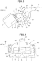
FIG. 4 is a rear view of a fuel battery and exhaust duct. -
FIG. 5 is a rear view of a small vehicle. -
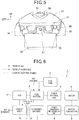
FIG. 6 is a block diagram of a fuel battery system. -
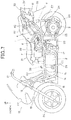
FIG. 7 is a side view of a small vehicle mounted with a fuel battery. - The present invention provides a small vehicle mounted with a fuel battery intended to achieve a smaller or reduced pressure loss at or along an exhaust duct by reducing the airflow resistance which results in smaller power consumption by a fan; and thereby, increase the efficiency of a fuel battery system.
- In
FIG. 6 , a fuel battery system 1 supplies hydrogen stored in afuel tank 2 and air sucked from the outside by afan 3 to afuel battery 4, to cause an electrochemical reaction to thereby generate electric power. Generated electric power is supplied to a power conversion anddistribution unit 6 by apower control unit 5. The power conversion anddistribution unit 6 supplies the electric power generated by thefuel battery 4 to asecondary battery 7 to charge the same with electric power. The electric power from thefuel battery 4 and/or thesecondary battery 7 is supplied to amotor 9 through amotor controller 8 to drive themotor 9. - In the fuel battery system 1, temperature of the
fuel battery 4 rises to a high degree due to hydrogen-oxygen reaction. A part of the air introduced by thefan 3 is circulated to cool down thefuel battery 4. After cooling thefuel battery 4, the air is exhausted through anexhaust duct 10. The hydrogen purged from thefuel battery 4 is discharged to theexhaust duct 10 through ahydrogen purge pipe 11. Apurge valve 12 controls the flow rate and timing of the hydrogen purged through thehydrogen purge pipe 11. - The fuel battery system 1 is mounted on a small vehicle (for example, a motorcycle) 13 as shown in
FIG. 7 . Thesmall vehicle 13 has a pair of right and leftmain frames 14 constituting the vehicle body. The pair ofmain frames 14 are formed in a generally U-like shape with a pair oflower frame portions 15, a pair offront frame portions 16 and a pair ofrear frame portions 17. The pair oflower frame portions 15 extend in a front-rear direction. The pair offront frame portions 16 extend sharply upward at an angle from the front side of the pair oflower frame portions 15. The pair ofrear frame portions 17 extend sharply upward at an angle from the rear side of the pair oflower frame portions 15. The pair ofrear frame portions 17 are bent in a half way, and then extend gently upward therefrom at an angle. - In the pair of right and left
main frames 14, the pair offront frame portions 16 extend sharply upward and are attached to ahead pipe 18, respectively at the front ends thereof. Thehead pipe 18 supports afront fork 19 so as to allow thefront fork 19 to steer rightward/leftward. The front fork 19 pivots afront wheel 20 at the lower end thereof. Ahandlebar 21 is attached to an upper end of thefront fork 19. Afront cover 22 covers thehead pipe 18. - In the pair of right and left
main frames 14, a pair ofupper frames 23 bridge the pair offront frame portions 16 and the pair ofrear frame portions 17, being connected at a midpoint thereof, respectively. A pair ofrear frames 24 connect at the rear end of the pair ofrear frame portions 17, respectively. The pair ofrear frames 24 curve upward at an angle and extend upward becoming gradually sharper toward the rear side, and then in the vicinity of the rear end thereof, gently extend straight upward at an angle. In the pair ofmain frames 14, the pair ofrear frame portions 17 pivot the front end of a pair ofswing arms 25. The pair ofswing arms 25 pivot arear wheel 26 as the drive wheel at the rear end thereof. A pair ofrear suspensions 27 connect between the pair ofswing arms 25 and the pair ofrear frames 24 to support the pair ofswing arms 25. In the pair ofmain frames 14, acenter stand 28 is provided to the pair oflower frame portions 15 at the rear side thereof and aside stand 29 is provided at the left side thereof - The pair of
upper frames 23 and the rear frames 24 are provided with amain body 30 attached thereto in the upper side thereof, and afront seat 31 and arear seat 32 are mounted thereon. Atail body 33 is attached to the pair of rear frames 24. Arear combination lamp 34 is attached to thetail body 33 in a lower portion thereof. Arear fender 35 is attached to therear combination lamp 34 in a lower portion thereof. Therear fender 35 is provided with anumber plate 36 and a numberplate illumination lamp 37 for illuminating thenumber plate 36 as shown inFIG. 5 . InFIG. 5 ,reference numeral 38 denotes a pair of right and left side fenders. - The
small vehicle 13 is mounted with thefuel tank 2 for the fuel battery system 1 disposed between the pair oflower frame portions 15, the pair offront frame portions 16 and the pair ofupper frames 23 connected to the pair ofrear frame portions 17 in the pair of right and leftmain frames 14. Thefuel tank 2 is provided with ahydrogen filling port 39. The power conversion anddistribution unit 6 and thesecondary battery 7 are mounted in an area above the pair ofrear frame portions 17 and the pair ofupper frames 23 and below themain body 30 in the pair ofmain frames 14. Thefan 3, thefuel battery 4 and theexhaust duct 10 are mounted in an area above the pair ofrear frames 24 and below themain body 30. Thehydrogen sensor 40 is provided in an area above thefuel battery 4 and below themain body 30. Themotor 9 is mounted on the pair ofswing arms 25. - The
small vehicle 13 is powered by driving themotor 9 using the electric power from thefuel battery 4 and/or thesecondary battery 7 to rotate therear wheel 26 as the drive wheel. - In the
small vehicle 13, thefuel battery 4 is mounted on the pair ofrear frames 24 constituting the vehicle body as shown inFIG. 1 and FIG. 2 . Thefuel battery 4 is formed in a box-like shape, which is longer in the width direction of the vehicle. Under thefuel battery 4, afan box 41 having a similar shape as thefuel battery 4 is attached to the pair ofrear frames 24 being inclined downward toward the front side. In thefan box 41, thefan 3 is provided for introducing air to thefuel battery 4. Anair outlet port 42 is formed behind thefan 3 in thefan box 41. - The
small vehicle 13 is provided with theexhaust duct 10 for exhausting the air introduced by thefan 3 to cool down thefuel battery 4. Theexhaust duct 10 is constituted of two-divided parts; i.e., afirst exhaust duct 43 and asecond exhaust duct 44. Thefirst exhaust duct 43 is connected to the rear side of thefan box 41 for guiding the air after cooling thefuel battery 4. Thesecond exhaust duct 44 is connected to the rear side of thefirst exhaust duct 43 avoiding the pair of rear frames 24. Thesecond exhaust duct 44 exhausts the air from thefirst exhaust duct 43 to the outside. - The
first exhaust duct 43 has a box-likefirst body 45 extending in the width direction of the vehicle. Thefirst body 45 is formed with afirst inlet port 46 in the front side thereof being connected to theair outlet port 42 of thefan box 41. Thefirst body 45 is formed with a firstcentral outlet port 47 in a central rear thereof as viewed in the longitudinal direction. Thefirst body 45 is formed with a firstside outlet port 48 at both sides respectively, in a slightly lower portion in a rear area as viewed in the longitudinal direction. - The
second exhaust duct 44 has asecond body 49 having a box-like shape extending in the width direction of the vehicle, and each of the both sides thereof is curved forward. Thesecond body 49 is formed with a secondcentral inlet port 50 in a central area thereof, as viewed in the longitudinal direction, connected to the firstcentral outlet port 47 of thefirst exhaust duct 43. Thesecond body 49 is formed with a secondside inlet port 51 in a front lower portion at both sides respectively, as viewed in the longitudinal direction thereof. The second side inlet port connects to the firstside outlet port 48 of thefirst exhaust duct 43. - As shown in
FIG. 3 , in thesecond exhaust duct 44, the secondcentral inlet port 50 is connected to the firstcentral outlet port 47; and the secondside inlet ports 51 connect to the firstside outlet ports 48 of thefirst exhaust duct 43 respectively, being interposed by aseal 52. - In the
small vehicle 13 mounted with thefuel battery 4 as described above, theexhaust duct 10 is divided into two parts: i.e., thefirst exhaust duct 43 and thesecond exhaust duct 44. Therefore, even when the frame has a complicated structure, the two-divided parts can easily connect to each other and avoid the pair of rear frames 24. A maximum space is ensured for the duct path under limitations due to the vehicle structure. - That is, as described above, the
exhaust duct 10 is divided into thefirst exhaust duct 43 and thesecond exhaust duct 44. Thefirst exhaust duct 43 is integrated with thefuel battery 4 and thefan box 41 as a module and assembled with the vehicle body first. After that, thesecond exhaust duct 44 is inserted into thefirst exhaust duct 43 from the rear side thereof. In order to avoid the pair ofrear frames 24 as shown inFIG. 2 , theexhaust duct 10 is arranged so that the firstcentral outlet port 47 and two firstside outlet ports 48 of thefirst exhaust duct 43 and the secondcentral inlet port 50 and two secondside inlet ports 51 of thesecond exhaust duct 44 are prepared separately and connected to each other afterward. Thus, theexhaust duct 10 is easily assembled with the vehicle body and a large space is ensured for the duct path. - Also, in the
small vehicle 13 mounted with thefuel battery 4, a large space is ensured for theexhaust duct 10. Therefore, theexhaust duct 10 achieves a smaller pressure loss and thus a smaller airflow resistance. As a result, afan 3 with a smaller output capacity may be employed; and accordingly, thefan 3 consumes less electric power. Thus, the fuel battery system 1 achieves higher system efficiency. - Further, in the
small vehicle 13 mounted with thefuel battery 4, thefirst exhaust duct 43 and thesecond exhaust duct 44 are connected to each other with interposition of theseal 52. Therefore, air tightness in the connected portion is ensured to prevent air leakage therefrom, and thus the air after cooling thefuel battery 4 is prevented from being fed back into the vehicle body. - Referring to
FIG. 3 and FIG. 4 , thefirst exhaust duct 43 is formed with a firstside drain port 53 at both sides, respectively, as viewed in the longitudinal direction of thefirst body 45, in the lowermost portion thereof. Each of the firstside drain ports 53 is provided for discharging water collected in thefirst body 45. Thefirst exhaust duct 43 is provided with thehydrogen purge pipe 11 being opened thereto in the vicinity of thefirst inlet port 46 connected to theair outlet port 42 of thefan 3 as shown inFIG. 3 . Thehydrogen purge pipe 11 is provided to discharge the hydrogen purged from thefuel battery 4. The hydrogen purged from thehydrogen purge pipe 11 is carried into thefirst exhaust duct 43 by the air flowing into thefirst inlet port 46 through theair outlet port 42. - With this arrangement, in the
small vehicle 13 mounted with thefuel battery 4, the hydrogen purged from the fuel battery system 1 is diffused swiftly by the airflow within theexhaust duct 10. Thus, the purged hydrogen is exhausted out, along with the air, from the rear side of the vehicle. Accordingly, the purged hydrogen is prevented from being fed back into the inside of the vehicle by external wind. - In the
second exhaust duct 44, the rear side of thesecond body 49 is bifurcated into a secondupper bifurcation 54 and a secondlower bifurcation 55 as shown inFIG. 3 and FIG. 4 . The secondupper bifurcation 54 guides the air flowing into thefirst exhaust duct 43 upward in a central area as viewed in the width direction of the vehicle. The secondlower bifurcation 55 guides the air downward to expand toward both sides thereof as viewed in the width direction of the vehicle. The secondupper bifurcation 54 is formed with a secondupper outlet port 56 opened to the rear side thereof in a central area as viewed in the width direction of the vehicle. The secondlower bifurcation 55 is formed with a secondlower outlet port 57, which expands to both sides of the upper outlet port as viewed in the width direction of the vehicle, and opens to the rear side of the vehicle. Thesecond exhaust duct 44 is formed so that the secondupper bifurcation 54 is inclined upward toward the rear side with respect to a horizontal line "H" inFIG. 3 . - The
second exhaust duct 44 is bifurcated into the secondupper bifurcation 54 and the secondlower bifurcation 55 to exhaust the air after cooling thefuel battery 4. By bifurcating thesecond exhaust duct 44 into the upper and lower two parts that avoid therear combination lamp 34, a larger area is ensured for the duct path. The secondupper outlet port 56 of the secondupper bifurcation 54, which is the highest portion in theexhaust duct 10, is open. With this arrangement, even when the hydrogen remains within theexhaust duct 10 and when thefuel battery 4 and thefan 3 stop operating, the hydrogen can swiftly go out of the vehicle due to the buoyancy of the hydrogen itself, the specific gravity of which is less than that of air, without depending on the airflow. - In the
small vehicle 13 mounted with thefuel battery 4, thesecond exhaust duct 44 is bifurcated into the upper and lower two parts and is opened to the rear side of the vehicle as described above. A large exhaust port is ensured while avoiding therear combination lamp 34 constituting the rear part of the vehicle. Accordingly, the pressure loss of the air is reduced. - Further, in the
small vehicle 13 mounted with thefuel battery 4, the secondupper bifurcation 54, which is the highest portion within theexhaust duct 10, is open at the secondupper outlet port 56. Even when the hydrogen remains mixed with the air within theexhaust duct 10 after thefan 3 stops operating, the hydrogen, the specific gravity of which is less than that of the air, goes upward due to the buoyancy thereof and rises upward. Thus, the hydrogen is prevented from remaining within theexhaust duct 10. - Furthermore, in the
small vehicle 13 mounted with thefuel battery 4, the secondupper bifurcation 54 is inclined upward toward the rear side. Therefore, even after thefan 3 stops operating, hydrogen, the specific gravity of which is less than that of air, is prevented from remaining within theexhaust duct 10. - The
second exhaust duct 44 is formed so that the secondupper bifurcation 54 is inclined upward toward the rear side of the vehicle as shown inFIG. 3 and FIG. 4 . Thesecond exhaust duct 44 is provided with awater reservoir 58 formed at the bottom of the secondlower bifurcation 55 as viewed in the width direction of the vehicle. Further, a secondwater drain port 59 is provided for draining water received in thewater reservoir 58 at the side that comes to the lower side when the vehicle is stayed or balanced on theside stand 29. In this embodiment, thedrain port 59 is located at the left side that comes to the lower side when the vehicle is balanced on theside stand 29. - The
water reservoir 58 of thesecond exhaust duct 44 receives water drops from condensation of vapor generated due to a reaction in thefuel battery 4 and rain water or the like entering from the outside. The water received by thewater reservoir 58 is discharged to the outside through the secondwater drain port 59. The secondwater drain port 59 is provided at the left side of thewater reservoir 58. When the small vehicle 1 is balanced on the side stand 29 located at the left side, the vehicle body is inclined leftward. With this, the received water is naturally drained from the left side. Different from thefirst exhaust duct 43, in the case where it is difficult to ensure a satisfactory water reservoir, by providing the firstside drain port 53 at both right and left sides respectively, the water can be swiftly drained. - As described above, in the
small vehicle 13 mounted with thefuel battery 4, thefuel battery 4 generates vapor due to the reaction therein and the vapor is condensed into water. Additionally, water enters into thesecond exhaust duct 44 from the outside. Such water is received by thewater reservoir 58 and discharged outside of the vehicle through the secondwater drain port 59. Thus, water is prevented from being fed back into thefuel battery 4. When the vehicle is stayed or parked at an incline, the water is drained swiftly through the secondwater drain port 59 formed at a lower side while the vehicle is stayed or balanced on theside stand 29. In thesmall vehicle 13 mounted with thefuel battery 4, since the water is not trapped within the vehicle, the weight thereof is reduced. - In the
second exhaust duct 44, the secondupper bifurcation 54 and the secondlower bifurcation 55 are formed so as to fit with and about the shape of therear combination lamp 34 and therear fender 35 as shown inFIG. 1 . - With this arrangement, in the
second exhaust duct 44, the secondupper bifurcation 54 and the secondlower bifurcation 55 are formed so as to fit with therear combination lamp 34 and therear fender 35 at ajoint portion 60 therebetween and are sealed to each other. As a result, the size and weight of thesecond exhaust duct 44 is reduced, resulting in a cost saving. Further, in thesecond exhaust duct 44, inversely proportional to the reduction of weight and thickness of the duct, the opening area of the exhaust port is increased. Since the airflow path is not limited by the thickness and outer wall, a larger space is ensured for the duct path. - The
rear fender 35 is formed in a shape that fits with the shape of the secondlower outlet port 57 of the secondlower bifurcation 55 while avoiding the numberplate illumination lamp 37 as shown inFIG. 5 . - As described above, in the
small vehicle 13 mounted with thefuel battery 4, the shape of therear fender 35 is formed so as to fit with the shape of the opening of the secondlower outlet port 57 to ensure or provide the opening marked with slash lines inFIG. 5 . Therefore, a large opening is ensured for the secondlower outlet port 57 without changing the installation position of thenumber plate 36 and the numberplate illumination lamp 37. As a result, airflow resistance is reduced without affecting the function of the numberplate illumination lamp 37. - The invention ensures a maximum space for the exhaust duct path under the limitations due to the structure of the small vehicle mounted with a fuel battery. The pressure loss and airflow resistance in the exhaust duct are reduced resulting in less electric power consumption by the fan to save electric power. The present invention is also applicable to electric bicycles driven by an air-cooled secondary battery with a cooling duct for providing electric power to a motor thereon.
Claims (7)
- A vehicle mounted with a fuel battery for generating electric power supplied to a motor for driving a drive wheel, the fuel battery being mounted on a frame acting as a vehicle body of the vehicle, comprising:- a fan box (41) having a fan for introducing air into the fuel battery (4); and- an exhaust duct (10) for exhausting the air introduced by the fan after cooling the fuel battery, wherein the exhaust duct is divided into two parts, comprising a first exhaust duct (43) connected to a rear side of the fan box (41), for introducing air after cooling the fuel battery and a second exhaust duct (44) connected to the rear side of the first exhaust duct (43) that avoids the frame, for exhausting air flowing thereinto from the first exhaust duct out of the vehicle body from the rear side thereof,wherein the second exhaust duct (44) is bifurcated into two parts; a second upper bifurcation (54) for guiding air flowing thereinto from the first exhaust duct in a central area thereof as viewed in the width direction of the vehicle and a second lower bifurcation (55) expanding in both sides thereof for guiding air downward as viewed in the width direction of the vehicle, the second upper bifurcation (54) being formed with a second upper outlet port opened to the rear side of the vehicle in a central area thereof as viewed in the width direction of the vehicle, and the second lower bifurcation (55) being formed with a second lower outlet port expanding to both sides thereof as viewed in the width direction of the vehicle and being opened to the rear side of the vehicle.
- The vehicle mounted with a fuel battery according to claim 1, wherein the first exhaust duct (43) is formed with a first inlet port (46) connected to an air outlet port (42) of the fan box (41), and
the first inlet port (46) is provided with a hydrogen purge pipe (11) opened in the vicinity thereof for discharging hydrogen purged from the fuel battery. - The vehicle mounted with a fuel battery according to claim 1 or 2, wherein the first exhaust duct (43) is connected to the second exhaust duct (44) with interposition of a seal therebetween.
- The vehicle mounted with a fuel battery according to one of claims 1 to 3, wherein the second exhaust duct (44) is formed so that the second upper bifurcation is inclined upward toward the rear side thereof.
- The vehicle mounted with a fuel battery according to one of claims 1 to claim 4, wherein the second exhaust duct (44) is provided with a water reservoir (58) at the bottom of the second lower bifurcation, and a second water drain port for draining water received in the water reservoir (58) at the side which moves to a lower position when the vehicle is inclined on a side stand.
- The vehicle mounted with a fuel battery according to one of claims 1 to 5, wherein, in the second exhaust duct (44), the second upper bifurcation and the second lower bifurcation are formed so as to fit with the shape of a rear combination lamp and a rear fender.
- The vehicle mounted with a fuel battery according to claim 6, wherein the rear fender is formed so as to fit with the shape of the second lower outlet port of the second lower bifurcation for avoiding a number plate illumination lamp.
Applications Claiming Priority (1)
| Application Number | Priority Date | Filing Date | Title |
|---|---|---|---|
| JP2009096677A JP5382325B2 (en) | 2009-04-13 | 2009-04-13 | A small vehicle equipped with a fuel cell |
Publications (2)
| Publication Number | Publication Date |
|---|---|
| EP2242139A1 EP2242139A1 (en) | 2010-10-20 |
| EP2242139B1 true EP2242139B1 (en) | 2017-04-05 |
Family
ID=42309171
Family Applications (1)
| Application Number | Title | Priority Date | Filing Date |
|---|---|---|---|
| EP10158230.2A Active EP2242139B1 (en) | 2009-04-13 | 2010-03-29 | Small vehicle mounted with a fuel cell |
Country Status (4)
| Country | Link |
|---|---|
| US (1) | US8215431B2 (en) |
| EP (1) | EP2242139B1 (en) |
| JP (1) | JP5382325B2 (en) |
| ES (1) | ES2631511T3 (en) |
Families Citing this family (9)
| Publication number | Priority date | Publication date | Assignee | Title |
|---|---|---|---|---|
| US9238497B2 (en) * | 2011-12-28 | 2016-01-19 | Kawasaki Jukogyo Kabushiki Kaisha | Electric motorcycle |
| CN103241336A (en) * | 2012-02-03 | 2013-08-14 | 江苏华源氢能科技发展有限公司 | Hydrogen-fuel-cell power system for electric bicycle |
| JP6273760B2 (en) * | 2013-10-18 | 2018-02-07 | スズキ株式会社 | Fuel cell motorcycle |
| JP6369217B2 (en) | 2014-08-20 | 2018-08-08 | スズキ株式会社 | Fuel cell motorcycle |
| JP6561769B2 (en) | 2015-10-27 | 2019-08-21 | スズキ株式会社 | Exhaust duct structure for fuel cell vehicles |
| JP6610198B2 (en) * | 2015-11-24 | 2019-11-27 | スズキ株式会社 | Hydrogen detector for fuel cell vehicle |
| JP6610299B2 (en) * | 2016-01-29 | 2019-11-27 | スズキ株式会社 | Air-cooled fuel cell exhaust system |
| JP6463318B2 (en) * | 2016-03-31 | 2019-01-30 | 本田技研工業株式会社 | Saddle riding |
| JP7358972B2 (en) * | 2019-12-20 | 2023-10-11 | スズキ株式会社 | fuel cell system |
Family Cites Families (8)
| Publication number | Priority date | Publication date | Assignee | Title |
|---|---|---|---|---|
| JP4292368B2 (en) * | 2002-12-12 | 2009-07-08 | ソニー株式会社 | Fuel cell and electronic device equipped with the same |
| JP4645006B2 (en) * | 2003-03-24 | 2011-03-09 | 株式会社エクォス・リサーチ | In-vehicle fuel cell system |
| JP4082597B2 (en) | 2003-07-11 | 2008-04-30 | 本田技研工業株式会社 | Fuel cell vehicle |
| ATE524847T1 (en) | 2003-10-24 | 2011-09-15 | Yamaha Motor Co Ltd | SADDLE-RIDE TYPE VEHICLE |
| KR100930475B1 (en) * | 2005-09-02 | 2009-12-09 | 주식회사 엘지화학 | Cooling system of vehicle battery pack including dual filter unit |
| JP4454574B2 (en) | 2005-11-30 | 2010-04-21 | 本田技研工業株式会社 | Cooling device for fuel cell vehicle |
| JP4998942B2 (en) * | 2007-03-06 | 2012-08-15 | 本田技研工業株式会社 | Fuel cell motorcycle |
| JP5076776B2 (en) * | 2007-09-25 | 2012-11-21 | スズキ株式会社 | Fuel cell motorcycle |
-
2009
- 2009-04-13 JP JP2009096677A patent/JP5382325B2/en active Active
-
2010
- 2010-01-22 US US12/657,546 patent/US8215431B2/en active Active
- 2010-03-29 EP EP10158230.2A patent/EP2242139B1/en active Active
- 2010-03-29 ES ES10158230.2T patent/ES2631511T3/en active Active
Non-Patent Citations (1)
| Title |
|---|
| None * |
Also Published As
| Publication number | Publication date |
|---|---|
| JP5382325B2 (en) | 2014-01-08 |
| US20100258374A1 (en) | 2010-10-14 |
| US8215431B2 (en) | 2012-07-10 |
| EP2242139A1 (en) | 2010-10-20 |
| ES2631511T3 (en) | 2017-08-31 |
| JP2010247574A (en) | 2010-11-04 |
Similar Documents
| Publication | Publication Date | Title |
|---|---|---|
| EP2242139B1 (en) | Small vehicle mounted with a fuel cell | |
| US9543598B2 (en) | Fuel cell-powered motorcycle | |
| CN101259863B (en) | fuel cell motorcycle | |
| CN101332767B (en) | Saddle riding type fuel cell vehicle | |
| US9490492B2 (en) | Air supply and exhaust structure for fuel cell | |
| CN1736748B (en) | Drainage structure in fuel cell electric vehicle | |
| CN100393574C (en) | Suspension device for fuel cell vehicles | |
| JP4583836B2 (en) | Fuel cell vehicle | |
| JP2016088160A (en) | Fuel cell two-wheeled vehicle | |
| JP6331838B2 (en) | Fuel cell motorcycle | |
| US20060040154A1 (en) | Fuel-cell vehicle | |
| JP4498856B2 (en) | Hydrogen filling port arrangement structure in fuel cell vehicle | |
| JP4855764B2 (en) | Fuel cell motorcycle | |
| JP2010232084A (en) | Battery mounting structure | |
| CN104554558A (en) | A two-wheel automobile adopting a fuel cell as power | |
| JP4455222B2 (en) | Intake / exhaust system member arrangement structure in fuel cell vehicle | |
| JP6273760B2 (en) | Fuel cell motorcycle | |
| JP4390439B2 (en) | Fuel cell system | |
| JP2006056355A (en) | Emission structure in fuel cell vehicle | |
| JP2011255827A (en) | Fuel cell motorcycle | |
| JP6471427B2 (en) | Fuel cell motorcycle | |
| JP2005150106A (en) | Fuel cell system and transportation equipment using the same | |
| JP4872559B2 (en) | Small electric vehicle with fuel cell | |
| JP2006056432A (en) | Fuel cell vehicle | |
| JP2005112094A (en) | Vehicle with fuel cell |
Legal Events
| Date | Code | Title | Description |
|---|---|---|---|
| PUAI | Public reference made under article 153(3) epc to a published international application that has entered the european phase |
Free format text: ORIGINAL CODE: 0009012 |
|
| 17P | Request for examination filed |
Effective date: 20100329 |
|
| AK | Designated contracting states |
Kind code of ref document: A1 Designated state(s): AT BE BG CH CY CZ DE DK EE ES FI FR GB GR HR HU IE IS IT LI LT LU LV MC MK MT NL NO PL PT RO SE SI SK SM TR |
|
| 17Q | First examination report despatched |
Effective date: 20140416 |
|
| REG | Reference to a national code |
Ref country code: DE Ref legal event code: R079 Ref document number: 602010041237 Country of ref document: DE Free format text: PREVIOUS MAIN CLASS: H01M0008040000 Ipc: B62K0011100000 |
|
| GRAP | Despatch of communication of intention to grant a patent |
Free format text: ORIGINAL CODE: EPIDOSNIGR1 |
|
| RIC1 | Information provided on ipc code assigned before grant |
Ipc: B62K 11/10 20060101AFI20161207BHEP Ipc: H01M 8/0662 20160101ALI20161207BHEP Ipc: H01M 8/04014 20160101ALI20161207BHEP |
|
| INTG | Intention to grant announced |
Effective date: 20170103 |
|
| GRAS | Grant fee paid |
Free format text: ORIGINAL CODE: EPIDOSNIGR3 |
|
| GRAA | (expected) grant |
Free format text: ORIGINAL CODE: 0009210 |
|
| AK | Designated contracting states |
Kind code of ref document: B1 Designated state(s): AT BE BG CH CY CZ DE DK EE ES FI FR GB GR HR HU IE IS IT LI LT LU LV MC MK MT NL NO PL PT RO SE SI SK SM TR |
|
| REG | Reference to a national code |
Ref country code: GB Ref legal event code: FG4D |
|
| REG | Reference to a national code |
Ref country code: CH Ref legal event code: EP |
|
| REG | Reference to a national code |
Ref country code: AT Ref legal event code: REF Ref document number: 881527 Country of ref document: AT Kind code of ref document: T Effective date: 20170415 |
|
| REG | Reference to a national code |
Ref country code: IE Ref legal event code: FG4D |
|
| REG | Reference to a national code |
Ref country code: DE Ref legal event code: R096 Ref document number: 602010041237 Country of ref document: DE |
|
| REG | Reference to a national code |
Ref country code: NL Ref legal event code: MP Effective date: 20170405 |
|
| REG | Reference to a national code |
Ref country code: LT Ref legal event code: MG4D |
|
| REG | Reference to a national code |
Ref country code: ES Ref legal event code: FG2A Ref document number: 2631511 Country of ref document: ES Kind code of ref document: T3 Effective date: 20170831 |
|
| REG | Reference to a national code |
Ref country code: AT Ref legal event code: MK05 Ref document number: 881527 Country of ref document: AT Kind code of ref document: T Effective date: 20170405 |
|
| PG25 | Lapsed in a contracting state [announced via postgrant information from national office to epo] |
Ref country code: NL Free format text: LAPSE BECAUSE OF FAILURE TO SUBMIT A TRANSLATION OF THE DESCRIPTION OR TO PAY THE FEE WITHIN THE PRESCRIBED TIME-LIMIT Effective date: 20170405 |
|
| PG25 | Lapsed in a contracting state [announced via postgrant information from national office to epo] |
Ref country code: FI Free format text: LAPSE BECAUSE OF FAILURE TO SUBMIT A TRANSLATION OF THE DESCRIPTION OR TO PAY THE FEE WITHIN THE PRESCRIBED TIME-LIMIT Effective date: 20170405 Ref country code: LT Free format text: LAPSE BECAUSE OF FAILURE TO SUBMIT A TRANSLATION OF THE DESCRIPTION OR TO PAY THE FEE WITHIN THE PRESCRIBED TIME-LIMIT Effective date: 20170405 Ref country code: HR Free format text: LAPSE BECAUSE OF FAILURE TO SUBMIT A TRANSLATION OF THE DESCRIPTION OR TO PAY THE FEE WITHIN THE PRESCRIBED TIME-LIMIT Effective date: 20170405 Ref country code: AT Free format text: LAPSE BECAUSE OF FAILURE TO SUBMIT A TRANSLATION OF THE DESCRIPTION OR TO PAY THE FEE WITHIN THE PRESCRIBED TIME-LIMIT Effective date: 20170405 Ref country code: GR Free format text: LAPSE BECAUSE OF FAILURE TO SUBMIT A TRANSLATION OF THE DESCRIPTION OR TO PAY THE FEE WITHIN THE PRESCRIBED TIME-LIMIT Effective date: 20170706 Ref country code: NO Free format text: LAPSE BECAUSE OF FAILURE TO SUBMIT A TRANSLATION OF THE DESCRIPTION OR TO PAY THE FEE WITHIN THE PRESCRIBED TIME-LIMIT Effective date: 20170705 |
|
| PG25 | Lapsed in a contracting state [announced via postgrant information from national office to epo] |
Ref country code: IS Free format text: LAPSE BECAUSE OF FAILURE TO SUBMIT A TRANSLATION OF THE DESCRIPTION OR TO PAY THE FEE WITHIN THE PRESCRIBED TIME-LIMIT Effective date: 20170805 Ref country code: BG Free format text: LAPSE BECAUSE OF FAILURE TO SUBMIT A TRANSLATION OF THE DESCRIPTION OR TO PAY THE FEE WITHIN THE PRESCRIBED TIME-LIMIT Effective date: 20170705 Ref country code: LV Free format text: LAPSE BECAUSE OF FAILURE TO SUBMIT A TRANSLATION OF THE DESCRIPTION OR TO PAY THE FEE WITHIN THE PRESCRIBED TIME-LIMIT Effective date: 20170405 Ref country code: SE Free format text: LAPSE BECAUSE OF FAILURE TO SUBMIT A TRANSLATION OF THE DESCRIPTION OR TO PAY THE FEE WITHIN THE PRESCRIBED TIME-LIMIT Effective date: 20170405 Ref country code: PL Free format text: LAPSE BECAUSE OF FAILURE TO SUBMIT A TRANSLATION OF THE DESCRIPTION OR TO PAY THE FEE WITHIN THE PRESCRIBED TIME-LIMIT Effective date: 20170405 |
|
| REG | Reference to a national code |
Ref country code: DE Ref legal event code: R097 Ref document number: 602010041237 Country of ref document: DE |
|
| PG25 | Lapsed in a contracting state [announced via postgrant information from national office to epo] |
Ref country code: CZ Free format text: LAPSE BECAUSE OF FAILURE TO SUBMIT A TRANSLATION OF THE DESCRIPTION OR TO PAY THE FEE WITHIN THE PRESCRIBED TIME-LIMIT Effective date: 20170405 Ref country code: EE Free format text: LAPSE BECAUSE OF FAILURE TO SUBMIT A TRANSLATION OF THE DESCRIPTION OR TO PAY THE FEE WITHIN THE PRESCRIBED TIME-LIMIT Effective date: 20170405 Ref country code: RO Free format text: LAPSE BECAUSE OF FAILURE TO SUBMIT A TRANSLATION OF THE DESCRIPTION OR TO PAY THE FEE WITHIN THE PRESCRIBED TIME-LIMIT Effective date: 20170405 Ref country code: SK Free format text: LAPSE BECAUSE OF FAILURE TO SUBMIT A TRANSLATION OF THE DESCRIPTION OR TO PAY THE FEE WITHIN THE PRESCRIBED TIME-LIMIT Effective date: 20170405 Ref country code: DK Free format text: LAPSE BECAUSE OF FAILURE TO SUBMIT A TRANSLATION OF THE DESCRIPTION OR TO PAY THE FEE WITHIN THE PRESCRIBED TIME-LIMIT Effective date: 20170405 |
|
| PLBE | No opposition filed within time limit |
Free format text: ORIGINAL CODE: 0009261 |
|
| STAA | Information on the status of an ep patent application or granted ep patent |
Free format text: STATUS: NO OPPOSITION FILED WITHIN TIME LIMIT |
|
| PG25 | Lapsed in a contracting state [announced via postgrant information from national office to epo] |
Ref country code: SM Free format text: LAPSE BECAUSE OF FAILURE TO SUBMIT A TRANSLATION OF THE DESCRIPTION OR TO PAY THE FEE WITHIN THE PRESCRIBED TIME-LIMIT Effective date: 20170405 |
|
| 26N | No opposition filed |
Effective date: 20180108 |
|
| PG25 | Lapsed in a contracting state [announced via postgrant information from national office to epo] |
Ref country code: SI Free format text: LAPSE BECAUSE OF FAILURE TO SUBMIT A TRANSLATION OF THE DESCRIPTION OR TO PAY THE FEE WITHIN THE PRESCRIBED TIME-LIMIT Effective date: 20170405 |
|
| REG | Reference to a national code |
Ref country code: DE Ref legal event code: R119 Ref document number: 602010041237 Country of ref document: DE |
|
| REG | Reference to a national code |
Ref country code: CH Ref legal event code: PL |
|
| GBPC | Gb: european patent ceased through non-payment of renewal fee |
Effective date: 20180329 |
|
| PG25 | Lapsed in a contracting state [announced via postgrant information from national office to epo] |
Ref country code: MC Free format text: LAPSE BECAUSE OF FAILURE TO SUBMIT A TRANSLATION OF THE DESCRIPTION OR TO PAY THE FEE WITHIN THE PRESCRIBED TIME-LIMIT Effective date: 20170405 |
|
| REG | Reference to a national code |
Ref country code: BE Ref legal event code: MM Effective date: 20180331 |
|
| REG | Reference to a national code |
Ref country code: IE Ref legal event code: MM4A |
|
| PG25 | Lapsed in a contracting state [announced via postgrant information from national office to epo] |
Ref country code: LU Free format text: LAPSE BECAUSE OF NON-PAYMENT OF DUE FEES Effective date: 20180329 |
|
| PG25 | Lapsed in a contracting state [announced via postgrant information from national office to epo] |
Ref country code: IE Free format text: LAPSE BECAUSE OF NON-PAYMENT OF DUE FEES Effective date: 20180329 Ref country code: DE Free format text: LAPSE BECAUSE OF NON-PAYMENT OF DUE FEES Effective date: 20181002 |
|
| PG25 | Lapsed in a contracting state [announced via postgrant information from national office to epo] |
Ref country code: BE Free format text: LAPSE BECAUSE OF NON-PAYMENT OF DUE FEES Effective date: 20180331 Ref country code: LI Free format text: LAPSE BECAUSE OF NON-PAYMENT OF DUE FEES Effective date: 20180331 Ref country code: CH Free format text: LAPSE BECAUSE OF NON-PAYMENT OF DUE FEES Effective date: 20180331 Ref country code: GB Free format text: LAPSE BECAUSE OF NON-PAYMENT OF DUE FEES Effective date: 20180329 |
|
| PG25 | Lapsed in a contracting state [announced via postgrant information from national office to epo] |
Ref country code: FR Free format text: LAPSE BECAUSE OF NON-PAYMENT OF DUE FEES Effective date: 20180331 |
|
| PG25 | Lapsed in a contracting state [announced via postgrant information from national office to epo] |
Ref country code: MT Free format text: LAPSE BECAUSE OF NON-PAYMENT OF DUE FEES Effective date: 20180329 |
|
| PG25 | Lapsed in a contracting state [announced via postgrant information from national office to epo] |
Ref country code: TR Free format text: LAPSE BECAUSE OF FAILURE TO SUBMIT A TRANSLATION OF THE DESCRIPTION OR TO PAY THE FEE WITHIN THE PRESCRIBED TIME-LIMIT Effective date: 20170405 |
|
| PG25 | Lapsed in a contracting state [announced via postgrant information from national office to epo] |
Ref country code: PT Free format text: LAPSE BECAUSE OF FAILURE TO SUBMIT A TRANSLATION OF THE DESCRIPTION OR TO PAY THE FEE WITHIN THE PRESCRIBED TIME-LIMIT Effective date: 20170405 Ref country code: HU Free format text: LAPSE BECAUSE OF FAILURE TO SUBMIT A TRANSLATION OF THE DESCRIPTION OR TO PAY THE FEE WITHIN THE PRESCRIBED TIME-LIMIT; INVALID AB INITIO Effective date: 20100329 |
|
| PG25 | Lapsed in a contracting state [announced via postgrant information from national office to epo] |
Ref country code: MK Free format text: LAPSE BECAUSE OF NON-PAYMENT OF DUE FEES Effective date: 20170405 Ref country code: CY Free format text: LAPSE BECAUSE OF FAILURE TO SUBMIT A TRANSLATION OF THE DESCRIPTION OR TO PAY THE FEE WITHIN THE PRESCRIBED TIME-LIMIT Effective date: 20170405 |
|
| PGFP | Annual fee paid to national office [announced via postgrant information from national office to epo] |
Ref country code: ES Payment date: 20250403 Year of fee payment: 16 |
|
| PGFP | Annual fee paid to national office [announced via postgrant information from national office to epo] |
Ref country code: IT Payment date: 20260220 Year of fee payment: 17 |