EP2241954B1 - Portable Electronic Device with Versatile Battery Compartment - Google Patents
Portable Electronic Device with Versatile Battery Compartment Download PDFInfo
- Publication number
- EP2241954B1 EP2241954B1 EP10166947A EP10166947A EP2241954B1 EP 2241954 B1 EP2241954 B1 EP 2241954B1 EP 10166947 A EP10166947 A EP 10166947A EP 10166947 A EP10166947 A EP 10166947A EP 2241954 B1 EP2241954 B1 EP 2241954B1
- Authority
- EP
- European Patent Office
- Prior art keywords
- battery
- cover
- battery compartment
- central portion
- outer frame
- Prior art date
- Legal status (The legal status is an assumption and is not a legal conclusion. Google has not performed a legal analysis and makes no representation as to the accuracy of the status listed.)
- Expired - Lifetime
Links
Images





Classifications
-
- H—ELECTRICITY
- H04—ELECTRIC COMMUNICATION TECHNIQUE
- H04M—TELEPHONIC COMMUNICATION
- H04M1/00—Substation equipment, e.g. for use by subscribers
- H04M1/02—Constructional features of telephone sets
- H04M1/0202—Portable telephone sets, e.g. cordless phones, mobile phones or bar type handsets
- H04M1/026—Details of the structure or mounting of specific components
- H04M1/0262—Details of the structure or mounting of specific components for a battery compartment
-
- G—PHYSICS
- G06—COMPUTING OR CALCULATING; COUNTING
- G06F—ELECTRIC DIGITAL DATA PROCESSING
- G06F1/00—Details not covered by groups G06F3/00 - G06F13/00 and G06F21/00
- G06F1/16—Constructional details or arrangements
- G06F1/1613—Constructional details or arrangements for portable computers
- G06F1/1626—Constructional details or arrangements for portable computers with a single-body enclosure integrating a flat display, e.g. Personal Digital Assistants [PDAs]
-
- G—PHYSICS
- G06—COMPUTING OR CALCULATING; COUNTING
- G06F—ELECTRIC DIGITAL DATA PROCESSING
- G06F1/00—Details not covered by groups G06F3/00 - G06F13/00 and G06F21/00
- G06F1/16—Constructional details or arrangements
- G06F1/1613—Constructional details or arrangements for portable computers
- G06F1/1633—Constructional details or arrangements of portable computers not specific to the type of enclosures covered by groups G06F1/1615 - G06F1/1626
- G06F1/1635—Details related to the integration of battery packs and other power supplies such as fuel cells or integrated AC adapter
-
- H—ELECTRICITY
- H01—ELECTRIC ELEMENTS
- H01M—PROCESSES OR MEANS, e.g. BATTERIES, FOR THE DIRECT CONVERSION OF CHEMICAL ENERGY INTO ELECTRICAL ENERGY
- H01M50/00—Constructional details or processes of manufacture of the non-active parts of electrochemical cells other than fuel cells, e.g. hybrid cells
- H01M50/20—Mountings; Secondary casings or frames; Racks, modules or packs; Suspension devices; Shock absorbers; Transport or carrying devices; Holders
- H01M50/267—Mountings; Secondary casings or frames; Racks, modules or packs; Suspension devices; Shock absorbers; Transport or carrying devices; Holders having means for adapting to batteries or cells of different types or different sizes
-
- H—ELECTRICITY
- H04—ELECTRIC COMMUNICATION TECHNIQUE
- H04B—TRANSMISSION
- H04B1/00—Details of transmission systems, not covered by a single one of groups H04B3/00 - H04B13/00; Details of transmission systems not characterised by the medium used for transmission
- H04B1/38—Transceivers, i.e. devices in which transmitter and receiver form a structural unit and in which at least one part is used for functions of transmitting and receiving
- H04B1/3827—Portable transceivers
- H04B1/3883—Arrangements for mounting batteries or battery chargers
-
- H—ELECTRICITY
- H05—ELECTRIC TECHNIQUES NOT OTHERWISE PROVIDED FOR
- H05K—PRINTED CIRCUITS; CASINGS OR CONSTRUCTIONAL DETAILS OF ELECTRIC APPARATUS; MANUFACTURE OF ASSEMBLAGES OF ELECTRICAL COMPONENTS
- H05K5/00—Casings, cabinets or drawers for electric apparatus
- H05K5/0086—Casings, cabinets or drawers for electric apparatus portable, e.g. battery operated apparatus
-
- Y—GENERAL TAGGING OF NEW TECHNOLOGICAL DEVELOPMENTS; GENERAL TAGGING OF CROSS-SECTIONAL TECHNOLOGIES SPANNING OVER SEVERAL SECTIONS OF THE IPC; TECHNICAL SUBJECTS COVERED BY FORMER USPC CROSS-REFERENCE ART COLLECTIONS [XRACs] AND DIGESTS
- Y02—TECHNOLOGIES OR APPLICATIONS FOR MITIGATION OR ADAPTATION AGAINST CLIMATE CHANGE
- Y02E—REDUCTION OF GREENHOUSE GAS [GHG] EMISSIONS, RELATED TO ENERGY GENERATION, TRANSMISSION OR DISTRIBUTION
- Y02E60/00—Enabling technologies; Technologies with a potential or indirect contribution to GHG emissions mitigation
- Y02E60/10—Energy storage using batteries
Definitions
- This invention relates to generally portable electronic devices, including but not limited to handheld wireless communication devices. More particularly, this invention relates to means of accommodating batteries of different sizes in such devices.
- Certain portable electronic devices handheld wireless communication devices in particular, are designed to provide various battery life options, depending on different capacity batteries being used. Batteries of different capacity tend to have different physical dimensions. These differences in dimension are typically compensated for by providing battery area access doors of varying dimension, i.e. a separate battery door for each possible battery. It would be preferable to avoid such separate battery doors.
- US-A-6048642 discloses a portable electronic device having a battery compartment with a removable cover able to slide relative to the battery compartment to accommodate batteries of different thickness.
- EP-A-1603246 falling under the provisions of Article 54(3)EPC discloses a portable electronic device having a battery compartment with a removable cover.
- US 2004/0233625 A1 also discloses.
- Such a device, said battery compartment and cover being configured to engage each other providing a battery compartment depth so accommodate batteries and further electronic components, wherein said batterycover comprises a central portion and an outer frame which has a shallow U-shape.
- the invention therefore preferably provides various means for accommodating batteries of different dimensions, without requiring separate battery doors.
- a portable electronic device comprising a battery compartment and a removable cover therefor, said battery compartment and cover being configured to engage each other in one of at least two discrete relative positions, each said position providing a different battery compartment depth to accommodate batteries of at least two different sizes; wherein said battery cover comprises an outer frame and a central portion which has a shallow U-shape with an outer flange of the central portion underlying an inwardly extending flange of the outer frame, such that rotation of said central portion between alternate orientations about an axis in the plane of the cover produces a smaller battery compartment in one orientation than in the other orientation.
- the central portion with its shallow U-shape is designed to engage the inwardly extending flange of the outer frame.
- the shallow U-shape is designed with a degree of flexibility that enables the outer flange of the central portion with its shallow U-shape to engage and disengage the inwardly extending flange of the outer frame.
- the central portion with its shallow U-shape comprises a base of generally rigid material and sides of a springy material.
- the at least two different sizes are discrete sizes.
- the at least two different sizes are various sizes along a continuum of sizes.
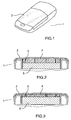
- Fig. 1 is a perspective view of a first example
- Fig. 2 is a cross-sectional elevation view of the first example, with a relatively thin battery
- Fig. 3 is a cross-sectional elevation view of the first example, with a somewhat thicker battery
- Fig. 4 is a perspective view of a second example, with a relatively thin battery
- Fig. 5 is another perspective view of the second example, with a somewhat thicker battery
- Fig. 6 is a cross-sectional elevation view of the second example, with a relatively thin battery
- Fig. 7 is a cross-sectional elevation view of the second example, with a somewhat thicker battery
- Fig. 8 is a perspective view of a third example, with a relatively thin battery
- Fig. 9 is another perspective view of the third example, with a somewhat thicker battery
- Fig. 10 is a cross-sectional elevation view of the third example, with a relatively thin battery
- Fig. 11 is a cross-sectional elevation view of the third example, with a somewhat thicker battery
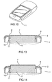
- Fig. 12 is a perspective view of a fourth example
- Fig. 13 is a cross-sectional elevation view of the fourth example, with a relatively thin battery
- Fig. 14 is a cross-sectional elevation view of the fourth example, with a somewhat thicker battery
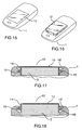
- Fig. 15 is a perspective view of a fifth example, with a relatively thin battery
- Fig. 16 is another perspective view of the fifth example, with a somewhat thicker battery
- Fig. 17 is a cross-sectional elevation view of the fifth example, with a relatively thin battery
- Fig. 18 is a cross-sectional elevation view of the fifth example, with a somewhat thicker battery
- Fig. 19 is a cross-sectional elevation view of a sixth example, similar to the fifth embodiment, with a relatively thin battery;
- Fig. 20 is a cross-sectional elevation view of the sixth example, with a somewhat thicker battery
- Fig. 21 is a perspective view of a seventh example
- Fig. 22 is a cross-sectional elevation view of a portion of the seventh example ;
- Fig. 23 is a cross-sectional elevation view of the seventh example, with a relatively thin battery
- Fig. 24 is a cross-sectional elevation view of the seventh example, with a somewhat thicker battery
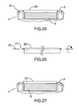
- Fig. 25 is a cross-sectional elevation view of an eighth example, with a relatively thin battery
- Fig. 26 is a cross-sectional elevation view of a portion of the cover of the eighth example.
- Fig. 27 is a cross-sectional elevation view of the eighth example, with a somewhat thicker battery
- Fig. 28 is a perspective view of the battery cover of an embodiment of the invention, in a position for a relatively thin battery;
- Fig. 29 is a cross-sectional elevation view the cover, corresponding to Fig. 28 ;
- Fig. 30 is a perspective view of the battery cover of the embodiment, in a position for a somewhat thicker battery.
- Fig. 31 is a cross-sectional elevation view the cover, corresponding to Fig. 30 .
- the handheld device 1 with a cover 2 secured to the device by any suitable conventional means, over a battery compartment 3.
- a battery compartment under the cover, are one or more elastomeric elements 4 which bear against an installed battery, 5 or 5'.
- Fig. 2 shows a relatively thin battery 5, such that the elastomeric elements are not compressed, or are compressed only sufficiently to keep the battery in position.
- Fig. 3 shows a somewhat thicker battery 5', such that the elastomeric elements are somewhat compressed, the compression creating more space to accommodate the larger battery.
- the handheld device 1 has a cover 2 secured to the device by any suitable conventional means, over the battery compartment 3.
- the cover has a generally rigid outer frame 6, for example of hard plastic or metal, and a generally rigid centre portion 7, again for example of hard plastic or metal.
- the outer frame and centre portion are connected by an elastomeric web portion 8, molded with or otherwise connected to both the outer frame and the centre portion.
- the centre portion 7 is in one position in Figs. 4 and 6 , relatively flat or generally co-planar with the outer frame 6 for example, to accommodate a relatively thin battery 5.
- the elastomeric web 8 is stretched, and the centre portion 7 is displaced outwardly, thereby accommodating a somewhat thicker battery 5'.
- FIG. 8-11 A third example, similar to the second example, is shown in Figs. 8-11 .
- this example there is no generally rigid centre portion. Instead, there is an elastomeric portion 9 secured to the outer frame 6, spanning across the battery compartment.
- the elastomeric portion 9 is in one position in Figs. 8 and 10 , relatively flat or generally co-planar with the outer frame 6 for example, to accommodate a relatively thin battery 5.
- the elastomeric portion 9 is stretched, particularly towards outer edges thereof, thereby accommodating a somewhat thicker battery 5'.
- FIG. 12-14 A fourth example, also similar to the second example, is shown in Figs. 12-14 .
- the cover again has a generally rigid outer frame 6 and a generally rigid centre portion 7, and the outer frame and centre portion are again connected by an elastomeric web portion.
- the elastomeric web portion 8' is in the form of a flexible membrane, molded with or otherwise connected to both the outer frame and the centre portion. The membrane tucks into a small gap 10 between the battery 5 or 5' and the side wall 11 of the battery compartment.
- Figs. 13 and 14 show the comparison between accommodating a relatively thin battery 5 and a somewhat thicker battery 5'.
- a battery cover 12 has an outer surface 13 and side walls 14 encompassing the battery 5 or 5'.
- the battery cover preferably is generally rigid, but could be somewhat flexible.
- Extending outwardly from the side walls 14 are flexible engagement means 15 such as elastomeric or otherwise flexible tabs or a flange, which can engage corresponding recesses 16 or 16' at two or more relative heights.
- the battery cover is installed by pressing it downwardly into the battery compartment, such that the flexible engagement means snap or pop into the relevant recess or recesses.
- One recess height, shown in Fig. 17 corresponds to a relatively thin battery 5, while the other recess height, shown in Fig.
- the flexible engagement means 15 could be tabs placed at several locations around the circumference of the battery cover, with recesses at corresponding locations, or could be in the form of a continuous flange extending all the way around the battery cover.
- the tabs or flange could be integral to the battery cover, or could be a separate piece.
- elastomeric tabs or an elastomeric flange are primarily contemplated, it should be appreciated that analogous means could be employed instead.
- the battery cover could be provided with a ball-spring arrangement, to engage detents at different heights in the battery compartment, or the reverse could be provided, i.e. ball-spring arrangements in the battery compartment, engaging detents in the side walls of the battery cover.
- Figs. 19 and 20 show a sixth example, very similar to the preceding example, in which the flexible engagement means 15 is in the form of elastomeric dimples engaging corresponding recesses.
- the ball-spring arrangement referred to above would be somewhat similar in concept and appearance.
- Figs. 21-24 show a seventh example, similar in concept to the second and fourth examples in particular.
- the cover has a generally rigid outer frame 6, for example of hard plastic or metal, and a generally rigid centre portion 7', again for example of hard plastic or metal.
- the outer frame and centre portion are connected by a web portion 8', molded with or otherwise connected to both the outer frame and the centre portion.
- This web portion 8' is of a springy material, biased to the position shown in Fig. 23 .
- the web portion 8' expands outwardly as shown in Fig. 24 .
- Figs. 25-27 show an eighth example, in which the battery cover 20 itself, or a portion thereof, is reversible and has tabs or flanges 21 displaced from the centreline 22. As can be seen from comparing Figs. 25 and 27 , flipping the cover or cover portion thus creates a smaller or larger space for the battery 5 or 5'.
- Figs. 28-31 show a exemplary embodiment of the invention, in which the battery cover 2 is in two pieces, namely an outer frame 24, and a central portion 25.
- the central portion can be installed in one of two positions, according to a principle somewhat similar to the preceding embodiment. Depending on which orientation is used, a smaller or larger space for the battery 5 or 5' is created.
- further aspects may include, for example, any other obvious variations as to how the battery cover may be configured or installed to provide varying battery compartment sizes; any obvious variations in choices of materials, degree of flexibility or resilience, if any, and any obvious variations in size, shape or other characteristics not relevant to the point of the invention. It should also be noted that although certain of the examples and embodiments above lend them selves to discrete battery sizes only, others (for example embodiments or examples with elastomeric elements) may lend themselves to a variety of battery sizes, along a continuum.
Landscapes
- Engineering & Computer Science (AREA)
- Theoretical Computer Science (AREA)
- Computer Hardware Design (AREA)
- Signal Processing (AREA)
- Human Computer Interaction (AREA)
- Physics & Mathematics (AREA)
- General Engineering & Computer Science (AREA)
- General Physics & Mathematics (AREA)
- Power Engineering (AREA)
- Computer Networks & Wireless Communication (AREA)
- Microelectronics & Electronic Packaging (AREA)
- Chemical & Material Sciences (AREA)
- Chemical Kinetics & Catalysis (AREA)
- Electrochemistry (AREA)
- General Chemical & Material Sciences (AREA)
- Battery Mounting, Suspending (AREA)
- Electric Clocks (AREA)
- Charge And Discharge Circuits For Batteries Or The Like (AREA)
- Hybrid Cells (AREA)
Abstract
Description
- This invention relates to generally portable electronic devices, including but not limited to handheld wireless communication devices. More particularly, this invention relates to means of accommodating batteries of different sizes in such devices.
- Certain portable electronic devices, handheld wireless communication devices in particular, are designed to provide various battery life options, depending on different capacity batteries being used. Batteries of different capacity tend to have different physical dimensions. These differences in dimension are typically compensated for by providing battery area access doors of varying dimension, i.e. a separate battery door for each possible battery. It would be preferable to avoid such separate battery doors.
-
US-A-6048642 discloses a portable electronic device having a battery compartment with a removable cover able to slide relative to the battery compartment to accommodate batteries of different thickness. -
EP-A-1603246 falling under the provisions of Article 54(3)EPC, discloses a portable electronic device having a battery compartment with a removable cover.US 2004/0233625 A1 also discloses. Such a device, said battery compartment and cover being configured to engage each other providing a battery compartment depth so accommodate batteries and further electronic components, wherein said batterycover comprises a central portion and an outer frame which has a shallow U-shape. - The invention therefore preferably provides various means for accommodating batteries of different dimensions, without requiring separate battery doors.
- Reference will be made to "relatively thin" batteries, and "somewhat thicker" batteries. It should be understood that "relatively thin" means relative to the thickness of the "somewhat thicker" batteries, and is not intended to indicate that the "relatively thin" battery is in fact thin compared to batteries in general.
- According to one exemplary embodiment there may be provided a portable electronic device comprising a battery compartment and a removable cover therefor, said battery compartment and cover being configured to engage each other in one of at least two discrete relative positions, each said position providing a different battery compartment depth to accommodate batteries of at least two different sizes; wherein said battery cover comprises an outer frame and a central portion which has a shallow U-shape with an outer flange of the central portion underlying an inwardly extending flange of the outer frame, such that rotation of said central portion between alternate orientations about an axis in the plane of the cover produces a smaller battery compartment in one orientation than in the other orientation.
- According to another exemplary embodiment, the central portion with its shallow U-shape is designed to engage the inwardly extending flange of the outer frame.
- According to another exemplary embodiment, the shallow U-shape is designed with a degree of flexibility that enables the outer flange of the central portion with its shallow U-shape to engage and disengage the inwardly extending flange of the outer frame.
- According to another exemplary embodiment, the central portion with its shallow U-shape comprises a base of generally rigid material and sides of a springy material.
- According to another exemplary embodiment, the at least two different sizes are discrete sizes.
- According to another exemplary embodiment, the at least two different sizes are various sizes along a continuum of sizes.
- Aspects of the invention will be described or will become apparent in the course of the following detailed description and drawings of specific embodiments of the invention, as examples only.
- Embodiments of the invention will now be described, by way of example only, with reference to the attached drawings, in which:
-
Fig. 1 is a perspective view of a first exemple, -
Fig. 2 is a cross-sectional elevation view of the first example, with a relatively thin battery; -
Fig. 3 is a cross-sectional elevation view of the first example, with a somewhat thicker battery; -
Fig. 4 is a perspective view of a second example, with a relatively thin battery; -
Fig. 5 is another perspective view of the second example, with a somewhat thicker battery; -
Fig. 6 is a cross-sectional elevation view of the second example, with a relatively thin battery; -
Fig. 7 is a cross-sectional elevation view of the second example, with a somewhat thicker battery; -
Fig. 8 is a perspective view of a third example, with a relatively thin battery; -
Fig. 9 is another perspective view of the third example, with a somewhat thicker battery; -
Fig. 10 is a cross-sectional elevation view of the third example, with a relatively thin battery; -
Fig. 11 is a cross-sectional elevation view of the third example, with a somewhat thicker battery; -
Fig. 12 is a perspective view of a fourth example; -
Fig. 13 is a cross-sectional elevation view of the fourth example, with a relatively thin battery; -
Fig. 14 is a cross-sectional elevation view of the fourth example, with a somewhat thicker battery; -
Fig. 15 is a perspective view of a fifth example, with a relatively thin battery; -
Fig. 16 is another perspective view of the fifth example, with a somewhat thicker battery; -
Fig. 17 is a cross-sectional elevation view of the fifth example, with a relatively thin battery; -
Fig. 18 is a cross-sectional elevation view of the fifth example, with a somewhat thicker battery; -
Fig. 19 is a cross-sectional elevation view of a sixth example, similar to the fifth embodiment, with a relatively thin battery; -
Fig. 20 is a cross-sectional elevation view of the sixth example, with a somewhat thicker battery; -
Fig. 21 is a perspective view of a seventh example; -
Fig. 22 is a cross-sectional elevation view of a portion of the seventh example ; -
Fig. 23 is a cross-sectional elevation view of the seventh example, with a relatively thin battery; -
Fig. 24 is a cross-sectional elevation view of the seventh example, with a somewhat thicker battery; -
Fig. 25 is a cross-sectional elevation view of an eighth example, with a relatively thin battery; -
Fig. 26 is a cross-sectional elevation view of a portion of the cover of the eighth example; -
Fig. 27 is a cross-sectional elevation view of the eighth example, with a somewhat thicker battery; -
Fig. 28 is a perspective view of the battery cover of an embodiment of the invention, in a position for a relatively thin battery; -
Fig. 29 is a cross-sectional elevation view the cover, corresponding toFig. 28 ; -
Fig. 30 is a perspective view of the battery cover of the embodiment, in a position for a somewhat thicker battery; and -
Fig. 31 is a cross-sectional elevation view the cover, corresponding toFig. 30 . - The accompanying drawings illustrate various aspects and exemples to accommodate batteries of different sizes.
- According to a first exemple, as shown in
Figs. 1-3 , thehandheld device 1 with acover 2 secured to the device by any suitable conventional means, over abattery compartment 3. Inside the battery compartment, under the cover, are one or moreelastomeric elements 4 which bear against an installed battery, 5 or 5'.Fig. 2 shows a relativelythin battery 5, such that the elastomeric elements are not compressed, or are compressed only sufficiently to keep the battery in position.Fig. 3 shows a somewhat thicker battery 5', such that the elastomeric elements are somewhat compressed, the compression creating more space to accommodate the larger battery. - According to a second exemple, as shown in
Figs. 4-7 , thehandheld device 1 has acover 2 secured to the device by any suitable conventional means, over thebattery compartment 3. The cover has a generally rigidouter frame 6, for example of hard plastic or metal, and a generallyrigid centre portion 7, again for example of hard plastic or metal. The outer frame and centre portion are connected by anelastomeric web portion 8, molded with or otherwise connected to both the outer frame and the centre portion. As can be seen from a comparison betweenFigs. 4 and 5 , or especially betweenFigs. 6 and 7 , thecentre portion 7 is in one position inFigs. 4 and 6 , relatively flat or generally co-planar with theouter frame 6 for example, to accommodate a relativelythin battery 5. InFigs. 5 and 7 , theelastomeric web 8 is stretched, and thecentre portion 7 is displaced outwardly, thereby accommodating a somewhat thicker battery 5'. - A third exemple, similar to the second example, is shown in
Figs. 8-11 . In this example, there is no generally rigid centre portion. Instead, there is anelastomeric portion 9 secured to theouter frame 6, spanning across the battery compartment. As can be seen from a comparison betweenFigs. 8 and 9 , or especially betweenFigs. 10 and 11 , theelastomeric portion 9 is in one position inFigs. 8 and 10 , relatively flat or generally co-planar with theouter frame 6 for example, to accommodate a relativelythin battery 5. InFigs. 9 and 11 , theelastomeric portion 9 is stretched, particularly towards outer edges thereof, thereby accommodating a somewhat thicker battery 5'. - A fourth exemple, also similar to the second example, is shown in
Figs. 12-14 . In this example, the cover again has a generally rigidouter frame 6 and a generallyrigid centre portion 7, and the outer frame and centre portion are again connected by an elastomeric web portion. However, the elastomeric web portion 8', is in the form of a flexible membrane, molded with or otherwise connected to both the outer frame and the centre portion. The membrane tucks into asmall gap 10 between thebattery 5 or 5' and theside wall 11 of the battery compartment. As with the previous examples,Figs. 13 and 14 show the comparison between accommodating a relativelythin battery 5 and a somewhat thicker battery 5'. - A fifth exemple is shown in
Figs. 15-18 . In this example, abattery cover 12 has anouter surface 13 andside walls 14 encompassing thebattery 5 or 5'. The battery cover preferably is generally rigid, but could be somewhat flexible. Extending outwardly from theside walls 14 are flexible engagement means 15 such as elastomeric or otherwise flexible tabs or a flange, which can engagecorresponding recesses 16 or 16' at two or more relative heights. The battery cover is installed by pressing it downwardly into the battery compartment, such that the flexible engagement means snap or pop into the relevant recess or recesses. One recess height, shown inFig. 17 , corresponds to a relativelythin battery 5, while the other recess height, shown inFig. 18 , corresponds to a somewhat thicker battery 5'. There could be additional recess heights if desired. The flexible engagement means 15 could be tabs placed at several locations around the circumference of the battery cover, with recesses at corresponding locations, or could be in the form of a continuous flange extending all the way around the battery cover. The tabs or flange could be integral to the battery cover, or could be a separate piece. Although elastomeric tabs or an elastomeric flange are primarily contemplated, it should be appreciated that analogous means could be employed instead. For example, the battery cover could be provided with a ball-spring arrangement, to engage detents at different heights in the battery compartment, or the reverse could be provided, i.e. ball-spring arrangements in the battery compartment, engaging detents in the side walls of the battery cover. -
Figs. 19 and 20 show a sixth exemple, very similar to the preceding example, in which the flexible engagement means 15 is in the form of elastomeric dimples engaging corresponding recesses. The ball-spring arrangement referred to above would be somewhat similar in concept and appearance. -
Figs. 21-24 show a seventh exemple, similar in concept to the second and fourth examples in particular. In this example, the cover has a generally rigidouter frame 6, for example of hard plastic or metal, and a generally rigid centre portion 7', again for example of hard plastic or metal. The outer frame and centre portion are connected by a web portion 8', molded with or otherwise connected to both the outer frame and the centre portion. This web portion 8' is of a springy material, biased to the position shown inFig. 23 . To accommodate a somewhat thicker battery 5', the web portion 8' expands outwardly as shown inFig. 24 . -
Figs. 25-27 show an eighth exemple, in which thebattery cover 20 itself, or a portion thereof, is reversible and has tabs orflanges 21 displaced from thecentreline 22. As can be seen from comparingFigs. 25 and 27 , flipping the cover or cover portion thus creates a smaller or larger space for thebattery 5 or 5'. -
Figs. 28-31 show a exemplary embodiment of the invention, in which thebattery cover 2 is in two pieces, namely anouter frame 24, and acentral portion 25. As can be readily seen from the drawings, the central portion can be installed in one of two positions, according to a principle somewhat similar to the preceding embodiment. Depending on which orientation is used, a smaller or larger space for thebattery 5 or 5' is created. - The preceding embodiment illustrates various aspects of the invention, but as example only. It will be appreciated that many additional variations and examples are possible, and will be apparent to those knowledgeable in the field of the invention. Thus the scope of the invention, as defined in the following claim, is not limited to these specific examples.
- Without limiting the generality of the foregoing, further aspects may include, for example, any other obvious variations as to how the battery cover may be configured or installed to provide varying battery compartment sizes; any obvious variations in choices of materials, degree of flexibility or resilience, if any, and any obvious variations in size, shape or other characteristics not relevant to the point of the invention. It should also be noted that although certain of the exemples and embodiments above lend them selves to discrete battery sizes only, others (for example embodiments or examples with elastomeric elements) may lend themselves to a variety of battery sizes, along a continuum.
- A portion of the disclosure of this document contains material which is subject to copyright protection. The copyright owner has no objection to the facsimile reproduction by anyone of the patent document or disclosure, as it appears in the Patent Office file or public records, but otherwise reserves all copyright protection whatsoever.
Claims (6)
- A portable electronic device (1) comprising a battery compartment (3) and a removable cover (2) therefor, said battery compartment (3) and cover (2) being configured to engage each other in one of at least two discrete relative positions, each said position providing a different battery compartment depth to accommodate batteries (5,5') of at least two different sizes,
wherein said battery cover (2) comprises an outer frame and a central portion which has a shallow U-shape with an outer flange (25) of the central portion underlying an inwardly extending flange (24) of the outer frame, such that rotation of said central portion between alternate orientations about an axis in the plane of the cover produces a smaller battery compartment in one orientation than in the other orientation. - The device of claim 1 wherein the central portion with its shallow U-shape is designed to engage the inwardly extending flange of the outer frame.
- The device of claim 1 wherein the shallow U-shape is designed with a degree of flexibility that enables the outer flange of the central portion with its shallow U-shape to engage and disengage the inwardly extending flange of the outer frame.
- The device of claim 1 wherein the central portion with its shallow U-shape comprises a base of generally rigid material and sides of a springy material.
- The device of claim 1 wherein the at least two different sizes are discrete sizes.
- The device of claim 1 wherein the at least two different sizes are various sizes along a continuum of sizes.
Applications Claiming Priority (3)
| Application Number | Priority Date | Filing Date | Title |
|---|---|---|---|
| EP05109309A EP1772797B1 (en) | 2005-10-07 | 2005-10-07 | Expandable battery compartment for handheld electronic devices |
| EP08166615A EP2012215B1 (en) | 2005-10-07 | 2005-10-07 | Portable Electronic Device with Versatile Battery Compartment |
| EP07104434A EP1881392B1 (en) | 2005-10-07 | 2005-10-07 | Versatile battery compartment for hand-held devices |
Related Parent Applications (3)
| Application Number | Title | Priority Date | Filing Date |
|---|---|---|---|
| EP05109309.4 Division | 2005-10-07 | ||
| EP07104434.1 Division | 2007-03-19 | ||
| EP08166615.8 Division | 2008-10-14 |
Publications (2)
| Publication Number | Publication Date |
|---|---|
| EP2241954A1 EP2241954A1 (en) | 2010-10-20 |
| EP2241954B1 true EP2241954B1 (en) | 2011-12-28 |
Family
ID=36021150
Family Applications (4)
| Application Number | Title | Priority Date | Filing Date |
|---|---|---|---|
| EP07104434A Expired - Lifetime EP1881392B1 (en) | 2005-10-07 | 2005-10-07 | Versatile battery compartment for hand-held devices |
| EP05109309A Expired - Lifetime EP1772797B1 (en) | 2005-10-07 | 2005-10-07 | Expandable battery compartment for handheld electronic devices |
| EP08166615A Expired - Lifetime EP2012215B1 (en) | 2005-10-07 | 2005-10-07 | Portable Electronic Device with Versatile Battery Compartment |
| EP10166947A Expired - Lifetime EP2241954B1 (en) | 2005-10-07 | 2005-10-07 | Portable Electronic Device with Versatile Battery Compartment |
Family Applications Before (3)
| Application Number | Title | Priority Date | Filing Date |
|---|---|---|---|
| EP07104434A Expired - Lifetime EP1881392B1 (en) | 2005-10-07 | 2005-10-07 | Versatile battery compartment for hand-held devices |
| EP05109309A Expired - Lifetime EP1772797B1 (en) | 2005-10-07 | 2005-10-07 | Expandable battery compartment for handheld electronic devices |
| EP08166615A Expired - Lifetime EP2012215B1 (en) | 2005-10-07 | 2005-10-07 | Portable Electronic Device with Versatile Battery Compartment |
Country Status (4)
| Country | Link |
|---|---|
| EP (4) | EP1881392B1 (en) |
| AT (4) | ATE364865T1 (en) |
| CA (3) | CA2557382C (en) |
| DE (3) | DE602005023917D1 (en) |
Families Citing this family (4)
| Publication number | Priority date | Publication date | Assignee | Title |
|---|---|---|---|---|
| JP5444741B2 (en) * | 2008-03-03 | 2014-03-19 | パナソニック株式会社 | Electronics |
| CN104244617B (en) * | 2013-06-09 | 2018-05-29 | 比亚迪股份有限公司 | A kind of housing and its preparation method and application |
| KR102296909B1 (en) * | 2015-01-09 | 2021-09-01 | 삼성전자주식회사 | Portable device comprising auxiliary battery and auxiliary battery charging method thereof |
| US11196119B2 (en) | 2018-09-26 | 2021-12-07 | Techtronic Cordless Gp | Collapsible cover for a battery pack |
Family Cites Families (11)
| Publication number | Priority date | Publication date | Assignee | Title |
|---|---|---|---|---|
| US4431717A (en) * | 1981-01-31 | 1984-02-14 | Sony Corporation | Battery case |
| US5015546A (en) * | 1989-06-12 | 1991-05-14 | Grid Systems Corporation | Battery compartment |
| US5744930A (en) * | 1997-02-06 | 1998-04-28 | Motorola, Inc. | Universal battery compartment |
| JPH113691A (en) * | 1997-06-09 | 1999-01-06 | Sony Corp | Electronics |
| US6048642A (en) | 1997-06-30 | 2000-04-11 | Lsi Logic Corporation | Adaptive clamping of an electrochemical cell within a replaceable container tray |
| US6228528B1 (en) * | 1998-12-21 | 2001-05-08 | Eveready Battery Company, Inc. | Protective electrochemical cell package |
| DE29916458U1 (en) * | 1999-09-18 | 2000-01-13 | Sennheiser electronic GmbH & Co. KG, 30900 Wedemark | Housing for a portable electrical device |
| JP3910507B2 (en) * | 2002-08-19 | 2007-04-25 | 富士フイルム株式会社 | Electronics |
| JP2004266407A (en) * | 2003-02-28 | 2004-09-24 | Hitachi Ltd | Mobile terminal adapter, mobile terminal, and method for selectively mounting mobile terminal adapter |
| US7299941B2 (en) * | 2003-04-15 | 2007-11-27 | Dart Industries Inc. | Container seal with flexible central panel |
| EP1603246B1 (en) | 2004-06-02 | 2007-03-21 | Research In Motion Limited | Slim line battery pack |
-
2005
- 2005-10-07 DE DE602005023917T patent/DE602005023917D1/en not_active Expired - Lifetime
- 2005-10-07 AT AT05109309T patent/ATE364865T1/en not_active IP Right Cessation
- 2005-10-07 AT AT08166615T patent/ATE483191T1/en not_active IP Right Cessation
- 2005-10-07 EP EP07104434A patent/EP1881392B1/en not_active Expired - Lifetime
- 2005-10-07 DE DE602005001403T patent/DE602005001403T2/en not_active Expired - Lifetime
- 2005-10-07 EP EP05109309A patent/EP1772797B1/en not_active Expired - Lifetime
- 2005-10-07 EP EP08166615A patent/EP2012215B1/en not_active Expired - Lifetime
- 2005-10-07 DE DE602005014285T patent/DE602005014285D1/en not_active Expired - Lifetime
- 2005-10-07 AT AT10166947T patent/ATE539398T1/en active
- 2005-10-07 EP EP10166947A patent/EP2241954B1/en not_active Expired - Lifetime
- 2005-10-07 AT AT07104434T patent/ATE430337T1/en not_active IP Right Cessation
-
2006
- 2006-08-25 CA CA002557382A patent/CA2557382C/en active Active
- 2006-08-25 CA CA2666328A patent/CA2666328C/en active Active
- 2006-08-25 CA CA2726141A patent/CA2726141C/en active Active
Also Published As
| Publication number | Publication date |
|---|---|
| EP2241954A1 (en) | 2010-10-20 |
| CA2666328A1 (en) | 2007-04-07 |
| EP2012215A3 (en) | 2009-04-15 |
| ATE430337T1 (en) | 2009-05-15 |
| EP1881392B1 (en) | 2009-04-29 |
| CA2666328C (en) | 2011-03-22 |
| CA2726141C (en) | 2016-03-15 |
| ATE483191T1 (en) | 2010-10-15 |
| DE602005023917D1 (en) | 2010-11-11 |
| DE602005001403D1 (en) | 2007-07-26 |
| ATE539398T1 (en) | 2012-01-15 |
| EP1881392A1 (en) | 2008-01-23 |
| CA2557382A1 (en) | 2007-04-07 |
| DE602005014285D1 (en) | 2009-06-10 |
| EP2012215A2 (en) | 2009-01-07 |
| EP1772797A1 (en) | 2007-04-11 |
| CA2557382C (en) | 2010-02-02 |
| ATE364865T1 (en) | 2007-07-15 |
| CA2726141A1 (en) | 2007-04-07 |
| EP1772797B1 (en) | 2007-06-13 |
| EP2012215B1 (en) | 2010-09-29 |
| DE602005001403T2 (en) | 2008-02-21 |
Similar Documents
| Publication | Publication Date | Title |
|---|---|---|
| US8142925B2 (en) | Expandable battery compartment for handheld electronic devices | |
| US6275002B1 (en) | Rotary charging plug structure of a charger | |
| US8409739B2 (en) | Battery latching mechanism having connecting block and receiving hole for portable electronic device | |
| JP4922444B2 (en) | Electronics | |
| JP5569275B2 (en) | Waterproof cover and electronic device | |
| US10773657B2 (en) | Removable electronic device holder | |
| US7002073B2 (en) | Latching assembly for a removable cover of a portable electronic device | |
| EP2241954B1 (en) | Portable Electronic Device with Versatile Battery Compartment | |
| EP1617446A1 (en) | Rotating input selection device | |
| US20080038050A1 (en) | Rotary mechanisms | |
| US20130286560A1 (en) | Battery cover assembly for portable electronic device | |
| US20050045522A1 (en) | Storage tray for thin dies | |
| US8076018B2 (en) | Battery cover assembly with a locking mechanism | |
| US20090223330A1 (en) | Adapter | |
| JPH07203527A (en) | Portable radio battery case | |
| JP3666101B2 (en) | Hinge device for refrigerator and method for processing hinge device | |
| JP4821317B2 (en) | Mounting structure of rotary knob | |
| US8343645B2 (en) | Battery cover assembly for portable electronic device | |
| JP2014012329A (en) | Puncher | |
| JP2004162734A (en) | Hinge construction | |
| JP2005310475A (en) | Switching device and electronic equipment | |
| JP2003013940A (en) | Bearing structure |
Legal Events
| Date | Code | Title | Description |
|---|---|---|---|
| PUAI | Public reference made under article 153(3) epc to a published international application that has entered the european phase |
Free format text: ORIGINAL CODE: 0009012 |
|
| 17P | Request for examination filed |
Effective date: 20100622 |
|
| AC | Divisional application: reference to earlier application |
Ref document number: 1772797 Country of ref document: EP Kind code of ref document: P Ref document number: 1881392 Country of ref document: EP Kind code of ref document: P Ref document number: 2012215 Country of ref document: EP Kind code of ref document: P |
|
| AK | Designated contracting states |
Kind code of ref document: A1 Designated state(s): AT BE BG CH CY CZ DE DK EE ES FI FR GB GR HU IE IS IT LI LT LU LV MC NL PL PT RO SE SI SK TR |
|
| AX | Request for extension of the european patent |
Extension state: AL BA HR MK YU |
|
| RIC1 | Information provided on ipc code assigned before grant |
Ipc: H01M 2/10 20060101ALI20110531BHEP Ipc: G06F 1/16 20060101AFI20110531BHEP Ipc: H04M 1/02 20060101ALI20110531BHEP Ipc: H05K 5/00 20060101ALI20110531BHEP Ipc: H04B 1/38 20060101ALI20110531BHEP |
|
| GRAP | Despatch of communication of intention to grant a patent |
Free format text: ORIGINAL CODE: EPIDOSNIGR1 |
|
| GRAS | Grant fee paid |
Free format text: ORIGINAL CODE: EPIDOSNIGR3 |
|
| GRAA | (expected) grant |
Free format text: ORIGINAL CODE: 0009210 |
|
| AC | Divisional application: reference to earlier application |
Ref document number: 2012215 Country of ref document: EP Kind code of ref document: P Ref document number: 1772797 Country of ref document: EP Kind code of ref document: P Ref document number: 1881392 Country of ref document: EP Kind code of ref document: P |
|
| AK | Designated contracting states |
Kind code of ref document: B1 Designated state(s): AT BE BG CH CY CZ DE DK EE ES FI FR GB GR HU IE IS IT LI LT LU LV MC NL PL PT RO SE SI SK TR |
|
| REG | Reference to a national code |
Ref country code: GB Ref legal event code: FG4D |
|
| REG | Reference to a national code |
Ref country code: CH Ref legal event code: EP |
|
| REG | Reference to a national code |
Ref country code: AT Ref legal event code: REF Ref document number: 539398 Country of ref document: AT Kind code of ref document: T Effective date: 20120115 |
|
| REG | Reference to a national code |
Ref country code: IE Ref legal event code: FG4D |
|
| REG | Reference to a national code |
Ref country code: DE Ref legal event code: R096 Ref document number: 602005031940 Country of ref document: DE Effective date: 20120308 |
|
| REG | Reference to a national code |
Ref country code: NL Ref legal event code: VDEP Effective date: 20111228 |
|
| PG25 | Lapsed in a contracting state [announced via postgrant information from national office to epo] |
Ref country code: LT Free format text: LAPSE BECAUSE OF FAILURE TO SUBMIT A TRANSLATION OF THE DESCRIPTION OR TO PAY THE FEE WITHIN THE PRESCRIBED TIME-LIMIT Effective date: 20111228 |
|
| LTIE | Lt: invalidation of european patent or patent extension |
Effective date: 20111228 |
|
| PG25 | Lapsed in a contracting state [announced via postgrant information from national office to epo] |
Ref country code: SE Free format text: LAPSE BECAUSE OF FAILURE TO SUBMIT A TRANSLATION OF THE DESCRIPTION OR TO PAY THE FEE WITHIN THE PRESCRIBED TIME-LIMIT Effective date: 20111228 Ref country code: SI Free format text: LAPSE BECAUSE OF FAILURE TO SUBMIT A TRANSLATION OF THE DESCRIPTION OR TO PAY THE FEE WITHIN THE PRESCRIBED TIME-LIMIT Effective date: 20111228 Ref country code: GR Free format text: LAPSE BECAUSE OF FAILURE TO SUBMIT A TRANSLATION OF THE DESCRIPTION OR TO PAY THE FEE WITHIN THE PRESCRIBED TIME-LIMIT Effective date: 20120329 Ref country code: LV Free format text: LAPSE BECAUSE OF FAILURE TO SUBMIT A TRANSLATION OF THE DESCRIPTION OR TO PAY THE FEE WITHIN THE PRESCRIBED TIME-LIMIT Effective date: 20111228 |
|
| PG25 | Lapsed in a contracting state [announced via postgrant information from national office to epo] |
Ref country code: BE Free format text: LAPSE BECAUSE OF FAILURE TO SUBMIT A TRANSLATION OF THE DESCRIPTION OR TO PAY THE FEE WITHIN THE PRESCRIBED TIME-LIMIT Effective date: 20111228 Ref country code: CY Free format text: LAPSE BECAUSE OF FAILURE TO SUBMIT A TRANSLATION OF THE DESCRIPTION OR TO PAY THE FEE WITHIN THE PRESCRIBED TIME-LIMIT Effective date: 20111228 |
|
| PG25 | Lapsed in a contracting state [announced via postgrant information from national office to epo] |
Ref country code: BG Free format text: LAPSE BECAUSE OF FAILURE TO SUBMIT A TRANSLATION OF THE DESCRIPTION OR TO PAY THE FEE WITHIN THE PRESCRIBED TIME-LIMIT Effective date: 20120328 Ref country code: CZ Free format text: LAPSE BECAUSE OF FAILURE TO SUBMIT A TRANSLATION OF THE DESCRIPTION OR TO PAY THE FEE WITHIN THE PRESCRIBED TIME-LIMIT Effective date: 20111228 Ref country code: EE Free format text: LAPSE BECAUSE OF FAILURE TO SUBMIT A TRANSLATION OF THE DESCRIPTION OR TO PAY THE FEE WITHIN THE PRESCRIBED TIME-LIMIT Effective date: 20111228 Ref country code: IS Free format text: LAPSE BECAUSE OF FAILURE TO SUBMIT A TRANSLATION OF THE DESCRIPTION OR TO PAY THE FEE WITHIN THE PRESCRIBED TIME-LIMIT Effective date: 20120428 Ref country code: NL Free format text: LAPSE BECAUSE OF FAILURE TO SUBMIT A TRANSLATION OF THE DESCRIPTION OR TO PAY THE FEE WITHIN THE PRESCRIBED TIME-LIMIT Effective date: 20111228 Ref country code: SK Free format text: LAPSE BECAUSE OF FAILURE TO SUBMIT A TRANSLATION OF THE DESCRIPTION OR TO PAY THE FEE WITHIN THE PRESCRIBED TIME-LIMIT Effective date: 20111228 |
|
| PG25 | Lapsed in a contracting state [announced via postgrant information from national office to epo] |
Ref country code: RO Free format text: LAPSE BECAUSE OF FAILURE TO SUBMIT A TRANSLATION OF THE DESCRIPTION OR TO PAY THE FEE WITHIN THE PRESCRIBED TIME-LIMIT Effective date: 20111228 Ref country code: PT Free format text: LAPSE BECAUSE OF FAILURE TO SUBMIT A TRANSLATION OF THE DESCRIPTION OR TO PAY THE FEE WITHIN THE PRESCRIBED TIME-LIMIT Effective date: 20120430 Ref country code: PL Free format text: LAPSE BECAUSE OF FAILURE TO SUBMIT A TRANSLATION OF THE DESCRIPTION OR TO PAY THE FEE WITHIN THE PRESCRIBED TIME-LIMIT Effective date: 20111228 |
|
| REG | Reference to a national code |
Ref country code: AT Ref legal event code: MK05 Ref document number: 539398 Country of ref document: AT Kind code of ref document: T Effective date: 20111228 |
|
| PG25 | Lapsed in a contracting state [announced via postgrant information from national office to epo] |
Ref country code: DK Free format text: LAPSE BECAUSE OF FAILURE TO SUBMIT A TRANSLATION OF THE DESCRIPTION OR TO PAY THE FEE WITHIN THE PRESCRIBED TIME-LIMIT Effective date: 20111228 |
|
| PLBE | No opposition filed within time limit |
Free format text: ORIGINAL CODE: 0009261 |
|
| STAA | Information on the status of an ep patent application or granted ep patent |
Free format text: STATUS: NO OPPOSITION FILED WITHIN TIME LIMIT |
|
| PG25 | Lapsed in a contracting state [announced via postgrant information from national office to epo] |
Ref country code: IT Free format text: LAPSE BECAUSE OF FAILURE TO SUBMIT A TRANSLATION OF THE DESCRIPTION OR TO PAY THE FEE WITHIN THE PRESCRIBED TIME-LIMIT Effective date: 20111228 |
|
| 26N | No opposition filed |
Effective date: 20121001 |
|
| REG | Reference to a national code |
Ref country code: DE Ref legal event code: R097 Ref document number: 602005031940 Country of ref document: DE Effective date: 20121001 |
|
| PG25 | Lapsed in a contracting state [announced via postgrant information from national office to epo] |
Ref country code: AT Free format text: LAPSE BECAUSE OF FAILURE TO SUBMIT A TRANSLATION OF THE DESCRIPTION OR TO PAY THE FEE WITHIN THE PRESCRIBED TIME-LIMIT Effective date: 20111228 |
|
| PG25 | Lapsed in a contracting state [announced via postgrant information from national office to epo] |
Ref country code: ES Free format text: LAPSE BECAUSE OF FAILURE TO SUBMIT A TRANSLATION OF THE DESCRIPTION OR TO PAY THE FEE WITHIN THE PRESCRIBED TIME-LIMIT Effective date: 20120408 |
|
| PG25 | Lapsed in a contracting state [announced via postgrant information from national office to epo] |
Ref country code: MC Free format text: LAPSE BECAUSE OF NON-PAYMENT OF DUE FEES Effective date: 20121031 |
|
| REG | Reference to a national code |
Ref country code: CH Ref legal event code: PL |
|
| PG25 | Lapsed in a contracting state [announced via postgrant information from national office to epo] |
Ref country code: FI Free format text: LAPSE BECAUSE OF FAILURE TO SUBMIT A TRANSLATION OF THE DESCRIPTION OR TO PAY THE FEE WITHIN THE PRESCRIBED TIME-LIMIT Effective date: 20111228 |
|
| REG | Reference to a national code |
Ref country code: IE Ref legal event code: MM4A |
|
| PG25 | Lapsed in a contracting state [announced via postgrant information from national office to epo] |
Ref country code: IE Free format text: LAPSE BECAUSE OF NON-PAYMENT OF DUE FEES Effective date: 20121007 Ref country code: LI Free format text: LAPSE BECAUSE OF NON-PAYMENT OF DUE FEES Effective date: 20121031 Ref country code: CH Free format text: LAPSE BECAUSE OF NON-PAYMENT OF DUE FEES Effective date: 20121031 |
|
| PG25 | Lapsed in a contracting state [announced via postgrant information from national office to epo] |
Ref country code: TR Free format text: LAPSE BECAUSE OF FAILURE TO SUBMIT A TRANSLATION OF THE DESCRIPTION OR TO PAY THE FEE WITHIN THE PRESCRIBED TIME-LIMIT Effective date: 20111228 |
|
| PG25 | Lapsed in a contracting state [announced via postgrant information from national office to epo] |
Ref country code: LU Free format text: LAPSE BECAUSE OF NON-PAYMENT OF DUE FEES Effective date: 20121007 |
|
| PG25 | Lapsed in a contracting state [announced via postgrant information from national office to epo] |
Ref country code: HU Free format text: LAPSE BECAUSE OF FAILURE TO SUBMIT A TRANSLATION OF THE DESCRIPTION OR TO PAY THE FEE WITHIN THE PRESCRIBED TIME-LIMIT Effective date: 20051007 |
|
| REG | Reference to a national code |
Ref country code: DE Ref legal event code: R082 Ref document number: 602005031940 Country of ref document: DE Representative=s name: MERH-IP MATIAS ERNY REICHL HOFFMANN, DE |
|
| REG | Reference to a national code |
Ref country code: DE Ref legal event code: R082 Ref document number: 602005031940 Country of ref document: DE Representative=s name: MERH-IP MATIAS ERNY REICHL HOFFMANN, DE Effective date: 20140925 Ref country code: DE Ref legal event code: R081 Ref document number: 602005031940 Country of ref document: DE Owner name: BLACKBERRY LIMITED, WATERLOO, CA Free format text: FORMER OWNER: RESEARCH IN MOTION LIMITED, WATERLOO, ONTARIO, CA Effective date: 20140925 Ref country code: DE Ref legal event code: R082 Ref document number: 602005031940 Country of ref document: DE Representative=s name: MERH-IP MATIAS ERNY REICHL HOFFMANN PATENTANWA, DE Effective date: 20140925 |
|
| REG | Reference to a national code |
Ref country code: FR Ref legal event code: PLFP Year of fee payment: 11 |
|
| REG | Reference to a national code |
Ref country code: FR Ref legal event code: PLFP Year of fee payment: 12 |
|
| REG | Reference to a national code |
Ref country code: FR Ref legal event code: PLFP Year of fee payment: 13 |
|
| REG | Reference to a national code |
Ref country code: FR Ref legal event code: PLFP Year of fee payment: 14 |
|
| REG | Reference to a national code |
Ref country code: DE Ref legal event code: R082 Ref document number: 602005031940 Country of ref document: DE Ref country code: DE Ref legal event code: R081 Ref document number: 602005031940 Country of ref document: DE Owner name: MALIKIE INNOVATIONS LTD., IE Free format text: FORMER OWNER: BLACKBERRY LIMITED, WATERLOO, ONTARIO, CA |
|
| PGFP | Annual fee paid to national office [announced via postgrant information from national office to epo] |
Ref country code: DE Payment date: 20241029 Year of fee payment: 20 |
|
| PGFP | Annual fee paid to national office [announced via postgrant information from national office to epo] |
Ref country code: GB Payment date: 20241022 Year of fee payment: 20 |
|
| PGFP | Annual fee paid to national office [announced via postgrant information from national office to epo] |
Ref country code: FR Payment date: 20241025 Year of fee payment: 20 |
|
| REG | Reference to a national code |
Ref country code: DE Ref legal event code: R071 Ref document number: 602005031940 Country of ref document: DE |
|
| REG | Reference to a national code |
Ref country code: GB Ref legal event code: PE20 Expiry date: 20251006 |