EP2241733A1 - Thermal control device for fluids circulating in a vehicle with heat engine and method implemented by this device - Google Patents
Thermal control device for fluids circulating in a vehicle with heat engine and method implemented by this device Download PDFInfo
- Publication number
- EP2241733A1 EP2241733A1 EP10168097A EP10168097A EP2241733A1 EP 2241733 A1 EP2241733 A1 EP 2241733A1 EP 10168097 A EP10168097 A EP 10168097A EP 10168097 A EP10168097 A EP 10168097A EP 2241733 A1 EP2241733 A1 EP 2241733A1
- Authority
- EP
- European Patent Office
- Prior art keywords
- coolant
- heat
- storage means
- engine
- thermal
- Prior art date
- Legal status (The legal status is an assumption and is not a legal conclusion. Google has not performed a legal analysis and makes no representation as to the accuracy of the status listed.)
- Withdrawn
Links
Images

Classifications
-
- F—MECHANICAL ENGINEERING; LIGHTING; HEATING; WEAPONS; BLASTING
- F02—COMBUSTION ENGINES; HOT-GAS OR COMBUSTION-PRODUCT ENGINE PLANTS
- F02N—STARTING OF COMBUSTION ENGINES; STARTING AIDS FOR SUCH ENGINES, NOT OTHERWISE PROVIDED FOR
- F02N19/00—Starting aids for combustion engines, not otherwise provided for
- F02N19/02—Aiding engine start by thermal means, e.g. using lighted wicks
- F02N19/04—Aiding engine start by thermal means, e.g. using lighted wicks by heating of fluids used in engines
- F02N19/10—Aiding engine start by thermal means, e.g. using lighted wicks by heating of fluids used in engines by heating of engine coolants
-
- B—PERFORMING OPERATIONS; TRANSPORTING
- B60—VEHICLES IN GENERAL
- B60H—ARRANGEMENTS OF HEATING, COOLING, VENTILATING OR OTHER AIR-TREATING DEVICES SPECIALLY ADAPTED FOR PASSENGER OR GOODS SPACES OF VEHICLES
- B60H1/00—Heating, cooling or ventilating [HVAC] devices
- B60H1/00314—Arrangements permitting a rapid heating of the heating liquid
-
- B—PERFORMING OPERATIONS; TRANSPORTING
- B60—VEHICLES IN GENERAL
- B60H—ARRANGEMENTS OF HEATING, COOLING, VENTILATING OR OTHER AIR-TREATING DEVICES SPECIALLY ADAPTED FOR PASSENGER OR GOODS SPACES OF VEHICLES
- B60H1/00—Heating, cooling or ventilating [HVAC] devices
- B60H1/00492—Heating, cooling or ventilating [HVAC] devices comprising regenerative heating or cooling means, e.g. heat accumulators
-
- F—MECHANICAL ENGINEERING; LIGHTING; HEATING; WEAPONS; BLASTING
- F01—MACHINES OR ENGINES IN GENERAL; ENGINE PLANTS IN GENERAL; STEAM ENGINES
- F01P—COOLING OF MACHINES OR ENGINES IN GENERAL; COOLING OF INTERNAL-COMBUSTION ENGINES
- F01P11/00—Component parts, details, or accessories not provided for in, or of interest apart from, groups F01P1/00 - F01P9/00
- F01P11/14—Indicating devices; Other safety devices
- F01P11/20—Indicating devices; Other safety devices concerning atmospheric freezing conditions, e.g. automatically draining or heating during frosty weather
-
- F—MECHANICAL ENGINEERING; LIGHTING; HEATING; WEAPONS; BLASTING
- F01—MACHINES OR ENGINES IN GENERAL; ENGINE PLANTS IN GENERAL; STEAM ENGINES
- F01P—COOLING OF MACHINES OR ENGINES IN GENERAL; COOLING OF INTERNAL-COMBUSTION ENGINES
- F01P3/00—Liquid cooling
- F01P3/20—Cooling circuits not specific to a single part of engine or machine
-
- F—MECHANICAL ENGINEERING; LIGHTING; HEATING; WEAPONS; BLASTING
- F01—MACHINES OR ENGINES IN GENERAL; ENGINE PLANTS IN GENERAL; STEAM ENGINES
- F01P—COOLING OF MACHINES OR ENGINES IN GENERAL; COOLING OF INTERNAL-COMBUSTION ENGINES
- F01P11/00—Component parts, details, or accessories not provided for in, or of interest apart from, groups F01P1/00 - F01P9/00
- F01P11/14—Indicating devices; Other safety devices
- F01P2011/205—Indicating devices; Other safety devices using heat-accumulators
-
- F—MECHANICAL ENGINEERING; LIGHTING; HEATING; WEAPONS; BLASTING
- F01—MACHINES OR ENGINES IN GENERAL; ENGINE PLANTS IN GENERAL; STEAM ENGINES
- F01P—COOLING OF MACHINES OR ENGINES IN GENERAL; COOLING OF INTERNAL-COMBUSTION ENGINES
- F01P2060/00—Cooling circuits using auxiliaries
- F01P2060/04—Lubricant cooler
-
- F—MECHANICAL ENGINEERING; LIGHTING; HEATING; WEAPONS; BLASTING
- F01—MACHINES OR ENGINES IN GENERAL; ENGINE PLANTS IN GENERAL; STEAM ENGINES
- F01P—COOLING OF MACHINES OR ENGINES IN GENERAL; COOLING OF INTERNAL-COMBUSTION ENGINES
- F01P2060/00—Cooling circuits using auxiliaries
- F01P2060/08—Cabin heater
-
- F—MECHANICAL ENGINEERING; LIGHTING; HEATING; WEAPONS; BLASTING
- F01—MACHINES OR ENGINES IN GENERAL; ENGINE PLANTS IN GENERAL; STEAM ENGINES
- F01P—COOLING OF MACHINES OR ENGINES IN GENERAL; COOLING OF INTERNAL-COMBUSTION ENGINES
- F01P2060/00—Cooling circuits using auxiliaries
- F01P2060/16—Outlet manifold
-
- F—MECHANICAL ENGINEERING; LIGHTING; HEATING; WEAPONS; BLASTING
- F01—MACHINES OR ENGINES IN GENERAL; ENGINE PLANTS IN GENERAL; STEAM ENGINES
- F01P—COOLING OF MACHINES OR ENGINES IN GENERAL; COOLING OF INTERNAL-COMBUSTION ENGINES
- F01P7/00—Controlling of coolant flow
- F01P7/14—Controlling of coolant flow the coolant being liquid
- F01P7/16—Controlling of coolant flow the coolant being liquid by thermostatic control
- F01P7/165—Controlling of coolant flow the coolant being liquid by thermostatic control characterised by systems with two or more loops
Definitions
- the present invention relates to a device for thermal regulation of fluids circulating in a vehicle with a heat engine and a method implemented by this device.
- the invention applies in particular to the thermal regulation of fluids circulating in a vehicle so as to participate in the operation of a diesel engine.
- This type of device can be used to heat the lubricating oil of an engine.
- the lubricating oil of the heat engine has a high viscosity which causes additional friction in the engine and therefore an overconsumption of fuel. This occurs especially when starting the vehicle when the engine and oil are cold.
- the type of device mentioned above can also be used to reduce the amount of nitrogen oxides emitted by a vehicle.
- the production of nitrogen oxides is related in particular to the temperature of the gas mixture introduced into the cylinders of the engine of the vehicle.
- the mixture of gases introduced into the cylinders comprises in particular intake air and, where appropriate, recirculated exhaust gas with intake air. These exhaust gases are commonly referred to as EGR (Exhaust Gas Recycling) recirculated exhaust gases.
- the temperature of the gas mixture introduced into the cylinders is lowered, which reduces the production of nitrogen oxides by the same amount.
- thermocontrol device comprising at least one coolant / fluid heat exchanger, in some vehicles for heating the lubricating oil and in other vehicles for cooling recirculated exhaust gas.
- Such a device can effectively reduce the overconsumption of fuel at the start of the vehicle, and also significantly reduces the production of nitrogen oxide. It is easy to set up since it uses the coolant coolant circuit of the engine, usually equipping the vehicle.
- the subject of the invention is also a process for the thermal regulation of fluids carried out by the device according to the invention, characterized in that the heat transfer liquid is circulated both in the liquid heat exchanger / gas heat exchanger. recirculated exhaust and the thermal storage means, this independently of the operation mode heating or regeneration of these storage means.
- the subject of the invention is also a method of thermal regulation of fluids implemented by the device according to the invention, characterized in that , the thermal storage means being in regeneration mode and the engine being running, the quantity of coolant circulating in the thermal storage means so as to avoid or minimize the heat exchange between the thermal storage means in regeneration mode and the heat transfer liquid.
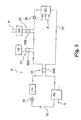
- FIG. 1 a device D according to a first embodiment of the invention for the thermal regulation of fluids flowing in a vehicle with a heat engine, for example of diesel type.
- the thermal control device D comprises a heat transfer liquid circuit 10 for cooling the heat engine 12 of the vehicle.
- the circuit 10 is connected to a portion of the engine 12 in which the heat transfer liquid circulates.
- the thermal control device D is intended to thermally regulate the lubricating oil of the heat engine 12, circulating in a circuit H, as well as recirculated exhaust gases flowing in a circuit G.
- the device D comprises a first exchanger 14 liquid coolant / lubricating oil and a second exchanger 16 coolant / recirculated exhaust gas connected to the circuit 10 of heat transfer liquid.
- the heat transfer liquid circuit 10 is further connected to a source or a heat sink providing a thermal energy that is usually not recovered (heat energy of the exhaust gas, residual heat, etc.).
- the source or the heat sink comprises, for example, thermal storage means 18 that can exchange heat with the coolant.
- the thermal storage means 18 comprise a chemical compound that stores or releases thermal energy by changing the phase and means for heat exchange between the coolant and the chemical compound.
- the storage means 18 can operate in at least two modes, namely a heating mode in which the heat of the storage means 18 is transferred to the heat transfer liquid of the circuit 10, and a regeneration mode in which the heat of the coolant is transferred to the storage means 18.
- the two heat exchangers 14 and 16 as well as the heat storage means 18 are connected in series in the heat transfer liquid circuit 10, in the order: thermal storage means 18, heat exchanger 14 coolant liquid / oil, exchanger 16 coolant liquid / recirculated exhaust gas, considering the direction of circulation of the coolant.
- the heat transfer liquid circuit 10 is connected to heat exchange means 20 between the coolant and air A intended to circulate in this passenger compartment.
- These heat exchange means 20 comprise for example a conventional air heater.
- the circuit 10 comprises multi-way valves which will be described below. Two channels are said to have the same signs if they form two inputs (or two outlets) of coolant. Two lanes are said to have opposite signs if they form one an inlet and the other a heat transfer fluid outlet.
- the heat transfer liquid circuit 10 comprises means 23 for bypassing the exchanger 14 heat transfer fluid / oil.
- the bypass means 23 comprise a bypass branch 24 of the liquid coolant / oil exchanger 14 and a three-way valve 26A.
- This valve 26A comprises two channels of the same signs forming a coolant outlet connected to the heat exchanger 14 and a heat transfer liquid outlet connected to the bypass branch 24, and a channel of opposite sign to the previous forming a heat transfer liquid inlet connected at the circuit 10, more particularly at the output of the thermal storage means 18.
- valve 26A may be placed at the outlet of the exchanger 14 and thus comprise two channels of the same signs forming a coolant inlet connected to the heat exchanger 14 and a coolant inlet connected to the branch branch 24, and a path of opposite sign to the previous' forming a heat transfer fluid outlet connected to the circuit 10, more particularly to the input of the heat exchange means 20.
- bypass branch 24 and the associated valve 26A can be replaced by a valve placed in the oil circuit H so as to isolate the heat exchanger 14 coolant / oil of this oil circuit H.
- the heat transfer liquid circuit 10 comprises means 27 for bypassing the thermal storage means 18.
- the bypass means 27 comprise a branch 28 of derivation of these thermal storage means 18 and a 30A three-way valve.
- This valve 30A comprises two channels of the same signs forming a heat transfer fluid outlet connected to the input of the thermal storage means 18 and a heat transfer fluid outlet connected to the branch branch 28, and a channel of opposite sign to the previous forming a heat transfer fluid inlet connected to the circuit 10, more particularly to the output of the motor 12.
- valve 30A may be placed at the outlet of the exchanger 18 and thus comprise two channels of the same signs forming a coolant inlet connected to the thermal storage means 18 and a coolant inlet connected to the bypass branch 28, and a channel of opposite sign to the previous forming a heat transfer liquid outlet connected to the circuit 10, more particularly to the inlet of the exchanger 14.
- the heat transfer liquid circuit 10 comprises means 33 for bypassing the engine 12.
- the bypass means 31 comprise a bypass branch 32 of this motor 12 and a three-way valve 34A.
- the valve 34A comprises two channels of the same signs forming a heat transfer liquid outlet connected to the inlet of the motor 12 (via the exchanger 16) and a heat transfer liquid outlet connected to the branch branch 32, and a opposite signal path to the previous forming a coolant inlet connected to the circuit 10, more particularly to the outlet of the exchanger 14 coolant / oil (through the heat exchange means 20).
- the valve 34A may comprise two tracks of the same signs forming a coolant outlet connected directly to the inlet of the engine 12 and a coolant outlet connected to the branch branch 32, and a channel of sign opposite to previous forming a coolant inlet connected to the outlet of the exchanger heat transfer liquid / recirculated exhaust gas.
- valve 34A can be placed at the output of the engine 12 and thus comprise two tracks of the same signs forming a coolant inlet connected to the output of the engine 12 and a coolant inlet connected to the branch branch 32 , and a path of opposite sign to the previous forming a coolant outlet connected to the circuit 10, more particularly to the inlet of the exchanger 18.
- the inlet of the valve 34A is connected to the outlet of the heat exchange means 20, that is to say at the outlet of the exchanger 14 via the heat exchange means 20.
- the coolant is circulated in the circuit 10 by means of a mechanical pump 36 driven by the engine 12.
- This mechanical pump 36 is connected to the circuit 10, for example upstream of the engine 12 .
- the heat-transfer liquid may, if appropriate, be circulated in the circuit 10 by means of an electric pump 38 connected to the circuit 10, for example between the liquid-coolant / oil-heat exchanger 14 and the heat exchange means 20.
- the electric pump 38 is able to circulate the coolant in the branch branch 32 of the motor 12.
- the mechanical pumps 36 and electrical 38 can operate simultaneously.
- the thermal control device D comprises a heat transfer fluid temperature sensor passing through the engine 12, an oil temperature sensor passing through the exchanger 14 and a temperature sensor. of the chemical compound of the storage means 18. These sensors are not shown.
- thermal control device D Some aspects of a possible operation of the thermal control device D according to the invention will be described below.
- This correlation is preferably achieved by driving, in accordance with the schematized method on the figure 2 , means for adjusting the amount of coolant or oil flowing in the exchanger 14, such as the valve 26A.
- the temperatures of the oil TH and the heat-transfer liquid TL are read and it is determined whether the temperature of the oil TH is lower than a predetermined temperature T, for example 110 ° C. (first condition 40).
- this first condition 40 is satisfied, that is to say if the temperature of the oil TH is lower than T, it is determined whether the temperature of the coolant TL is greater than the temperature of the oil TH (second condition 42), which occurs in particular when the thermal storage means 18 are in the heating mode. It will be noted that the thermal storage means 18 are in the heating mode, in particular during a period T1 of a few minutes following the start of the engine, for example 5 minutes.
- the amounts of heat transfer fluid and oil circulating in the exchanger 14 are adjusted so as to promote heating oil by heat exchange with the relatively hot heat transfer liquid (step 44).
- this adjustment is carried out by adjusting the valve 26A so as to circulate the coolant in the exchanger 14 heat transfer fluid / oil.
- This adjustment allows a rapid rise in temperature of the engine lubricating oil 12.
- the heat transmitted to the coolant by the thermal storage means 18 is transferred, at least in part, to the lubricating oil in the engine. exchanger 14 (which is disposed downstream of the storage means 18 in the circuit 10).
- the second condition 42 is not realized, that is to say if the temperature of the coolant TL is lower than TH (which can occur when the thermal storage means 18 are in regeneration mode), regulates the amounts of coolant and oil circulating in the exchanger 14 so as to avoid or minimize the heat exchange between the oil and the relatively cool heat transfer liquid and thus the cooling of this oil (step 48).
- this adjustment can be achieved by adjusting the valve 26A associated with the branch branch 24 of the exchanger 14 so as to circulate the coolant in this branch branch 24 or so as to distribute the coolant for the most part in branch branch 24 and for the smallest part in exchanger 14 to avoid any risk of boiling residual heat transfer fluid in exchanger 14.
- the amounts of coolant and oil circulating in the exchanger 14 are adjusted so to promote the cooling of the oil (up to for example the temperature T) by heat exchange with the coolant (step 44).
- this adjustment is made by adjusting the valve 26A so as to circulate the coolant 10 in the heat exchanger 14 coolant / oil.
- the coolant liquid is likely to circulate both in the recirculated coolant / exhaust gas heat exchanger 16 and the thermal storage means 18, independently of the operation in the heating or regeneration mode of these storage means 18.
- the exhaust gases can be recirculated when the motor 12 is running.
- the thermal storage means 18 are likely to be in heat exchange with the coolant liquid, on the one hand, when the thermal storage means 18 are in the heating mode, to transfer heat to the coolant (especially during the period T1 a few minutes after starting the engine) and, secondly, when the thermal storage means 18 are in regeneration mode, to take heat from the coolant (usually during a T2 period of ten minutes).
- the quantity of coolant circulating in the thermal storage means 18 is adjusted so as to avoid or minimize the heat exchange between the thermal storage means 18 in the regeneration mode and the relatively hot heat transfer liquid.
- this adjustment can be made by adjusting the valve 30A associated with the branch branch of the thermal storage means 18 so as to circulate the coolant in this branch branch 28.
- the heat of the coolant which comes in particular from the engine 12, is not transferred to the thermal storage means 18, so that the air of the passenger compartment can, by passing through the heat exchange means 20, collect a greater amount of heat to the coolant.
- the heating of the passenger compartment is generally desired in climatic conditions such as the temperature of the environment outside the vehicle is relatively low.
- climatic conditions such as the temperature of the environment outside the vehicle is relatively low.
- problems of emission of nitrogen oxides into the environment are much less exacerbated.
- This first category of condition (s) includes for example a voluntary command stopping the engine by the user.
- the amount of coolant circulating in the thermal storage means 18 is regulated so as to avoid or minimize the heat exchange between the heat storage means 18 in the heating mode and the heat transfer liquid in order to conserve the heat in stock until a next start of the motor 12.
- this adjustment can be made by adjusting the valve 30A associated with the bypass branch 28 of the thermal storage means 18 so as to circulate the heat transfer fluid in this diversion branch 28.
- the coolant liquid is circulated in the circuit 10 by means of the electric pump 38.
- the cabin air is heated by passing through the heat exchange means 20 so as to take heat from the heat transfer liquid, this heat coming from other members connected to the circuit 10 that the thermal storage means 18, in particular the engine 12 still relatively hot.
- This second category of condition (s) comprises, for example, an engine stop command by a vehicle computer (this type of stop is generally short-lived), a hazard warning light of the vehicle accompanying a stopping of the engine, a malfunction of the vehicle imposing a stopping of the engine or a heating control of the cabin air anticipating engine starting generally following a prolonged stop of the vehicle.
- the quantity of coolant circulating in the thermal storage means 18 is adjusted so as to promote the heating of the coolant by heat exchange with these storage means 18 and thus optimize the efficiency of the heating of the air the cockpit.
- this adjustment can be achieved by adjusting the valve 30A so as to circulate the coolant in the thermal storage means 18.
- the coolant liquid is circulated in the circuit 10 by means of the electric pump 38.
- the cabin air is heated by passing through the heat exchange means 20 so as to take heat from the heat transfer liquid, this heat coming, for a relatively large part, thermal storage means 18.
- a device D according to a second embodiment of the invention for the thermal regulation of fluids flowing in a vehicle with a heat engine, for example of diesel type.
- each branch branch 24, 28 and 32, and its associated valve 26A, 30A and 34A has been replaced by a four-way valve.
- the heat transfer liquid circuit 10 may further comprise a bypass branch of the recirculated liquid cooler / exhaust gas exchanger 16, driven by a valve, similarly to the bypass of the exchanger 14.
- the thermal storage means may be replaced by other means forming a source or a heat sink.
- Additional means for heating the heat transfer liquid such as electrical resistances or a burner (possibly programmable), may be provided on the circuit 10 between the output of the motor 12 and the heat exchange means 20.
- the invention can also be applied to vehicles operating with a gasoline engine.
Landscapes
- Engineering & Computer Science (AREA)
- Mechanical Engineering (AREA)
- Chemical & Material Sciences (AREA)
- Combustion & Propulsion (AREA)
- General Engineering & Computer Science (AREA)
- Thermal Sciences (AREA)
- Physics & Mathematics (AREA)
- Life Sciences & Earth Sciences (AREA)
- Atmospheric Sciences (AREA)
- Air-Conditioning For Vehicles (AREA)
- Output Control And Ontrol Of Special Type Engine (AREA)
- Exhaust-Gas Circulating Devices (AREA)
- Lubrication Of Internal Combustion Engines (AREA)
- Motor Or Generator Cooling System (AREA)
Abstract
Description
La présente invention concerne un dispositif de régulation thermique de fluides circulant dans un véhicule à moteur thermique et un procédé mis en oeuvre par ce dispositif.The present invention relates to a device for thermal regulation of fluids circulating in a vehicle with a heat engine and a method implemented by this device.
L'invention s'applique notamment à la régulation thermique de fluides circulant dans un véhicule de façon à participer au fonctionnement d'un moteur Diesel.The invention applies in particular to the thermal regulation of fluids circulating in a vehicle so as to participate in the operation of a diesel engine.
On connaît déjà dans l'état de la technique un dispositif de régulation thermique de fluides circulant dans un véhicule à moteur thermique, du type comprenant un circuit dans lequel circule un liquide caloporteur de refroidissement du moteur thermique et au moins un échangeur de chaleur liquide caloporteur / fluide à réguler.Already known in the state of the art a device for thermal regulation of fluids flowing in a heat engine vehicle, of the type comprising a circuit in which circulates a thermal coolant of the heat engine and at least one heat transfer liquid heat exchanger / fluid to be regulated.
Ce type de dispositif peut être utilisé pour réchauffer l'huile de lubrification d'un moteur.This type of device can be used to heat the lubricating oil of an engine.
En effet, à basse température, l'huile de lubrification du moteur thermique a une viscosité élevée ce qui entraîne des frottements supplémentaires dans le moteur et par conséquent une surconsommation de carburant. Celle-ci intervient notamment au démarrage du véhicule lorsque le moteur thermique et l'huile sont froids.In fact, at low temperature, the lubricating oil of the heat engine has a high viscosity which causes additional friction in the engine and therefore an overconsumption of fuel. This occurs especially when starting the vehicle when the engine and oil are cold.
Il est connu d'utiliser un échangeur de chaleur liquide caloporteur / huile de lubrification pour accélérer la montée en température de l'huile au démarrage.It is known to use a liquid heat exchanger heat / lubricating oil to accelerate the temperature rise of the oil at startup.
Le type de dispositif précité peut être également utilisé pour réduire la quantité d'oxydes d'azote émis par un véhicule.The type of device mentioned above can also be used to reduce the amount of nitrogen oxides emitted by a vehicle.
En effet, la production d'oxydes d'azote (NOx) est liée notamment à la température du mélange de gaz introduit dans les cylindres du moteur thermique du véhicule. Plus la température du mélange est élevée, plus la production d'oxydes d'azote est importante. Le mélange de gaz introduit dans les cylindres comprend notamment de l'air d'admission et, le cas échéant, des gaz d'échappement remis en circulation avec de l'air d'admission. Ces gaz d'échappement sont communément appelés gaz d'échappement recirculés EGR (Exhaust Gaz Recycling).Indeed, the production of nitrogen oxides (NO x ) is related in particular to the temperature of the gas mixture introduced into the cylinders of the engine of the vehicle. The higher the temperature of the mixture, the greater the production of nitrogen oxides. The mixture of gases introduced into the cylinders comprises in particular intake air and, where appropriate, recirculated exhaust gas with intake air. These exhaust gases are commonly referred to as EGR (Exhaust Gas Recycling) recirculated exhaust gases.
En abaissant la température des gaz recirculés, par exemple avec un échangeur de chaleur liquide caloporteur / gaz d'échappement recirculés, on abaisse la température du mélange de gaz introduit dans les cylindres ce qui réduit d'autant la production d'oxydes d'azote.By lowering the temperature of the recirculated gases, for example with a recirculated liquid heat exchanger / exhaust gas heat exchanger, the temperature of the gas mixture introduced into the cylinders is lowered, which reduces the production of nitrogen oxides by the same amount. .
Ainsi, il est connu d'utiliser un dispositif de régulation thermique comprenant au moins un échangeur de chaleur liquide caloporteur / fluide, dans certains véhicules pour réchauffer l'huile de lubrification et dans d'autres véhicules pour refroidir des gaz d'échappement recirculés.Thus, it is known to use a thermal control device comprising at least one coolant / fluid heat exchanger, in some vehicles for heating the lubricating oil and in other vehicles for cooling recirculated exhaust gas.
Afin de réduire les coûtes, il est souhaitable de disposer de moyens aussi simples et efficaces que possible pour réaliser les régulations thermiques des fluides cités précédemment.In order to reduce the costs, it is desirable to have means as simple and effective as possible to achieve the thermal regulations of the fluids mentioned above.
A cet effet, l'invention a pour objet un dispositif de régulation thermique de fluides circulant dans un véhicule à moteur thermique, du type précité, caractérisé en ce qu'il est destiné à réguler thermiquement des premier et deuxième fluides formés respectivement par de l'huile de lubrification du moteur thermique du véhicule et par des gaz d'échappement recirculés, et en ce qu'il comprend :
- un premier échangeur liquide caloporteur / huile de lubrification,
- un second échangeur liquide caloporteur / gaz d'échappement recirculés, les premier et second échangeurs étant raccordés à un même circuit de liquide caloporteur.
- a first liquid heat exchanger / lubricating oil,
- a second heat exchanger coolant / exhaust gas recirculated, the first and second exchangers being connected to the same coolant circuit.
Un tel dispositif permet de réduire efficacement la surconsommation de carburant au démarrage du véhicule, et permet également de réduire notablement la production d'oxyde d'azote. Il est simple à mettre en place puisqu'il utilise le circuit de liquide caloporteur de refroidissement du moteur, équipant habituellement le véhicule.Such a device can effectively reduce the overconsumption of fuel at the start of the vehicle, and also significantly reduces the production of nitrogen oxide. It is easy to set up since it uses the coolant coolant circuit of the engine, usually equipping the vehicle.
Un dispositif de régulation thermique selon l'invention peut en outre comporter l'une ou plusieurs des caractéristiques suivantes :
- le circuit de liquide caloporteur est raccordé à une source ou à un puits de chaleur ;
- la source ou le puits de chaleur comprend des moyens de stockage thermique pouvant échanger de la chaleur avec le liquide caloporteur, notamment pendant un mode de chauffage, dans lequel la chaleur des moyens de stockage est transférée au liquide caloporteur, et pendant un mode de régénération, dans lequel la chaleur du liquide caloporteur est transférée aux moyens de stockage ;
- les moyens de stockage thermiques comprennent un composé chimique stockant ou libérant de l'énergie thermique en changeant de phase;
- les deux échangeurs et la source ou le puits de chaleur sont raccordés en série dans le circuit de liquide caloporteur, dans l'ordre : source ou puits de chaleur, échangeur liquide caloporteur / huile, échangeur liquide caloporteur / gaz d'échappement recirculés, en considérant le sens de circulation du liquide caloporteur dans le circuit ;
- le circuit de liquide caloporteur comprend des moyens de dérivation de l'échangeur liquide caloporteur / huile ;
- les moyens de dérivation de l'échangeur liquide caloporteur / huile comprennent une branche de dérivation de l'échangeur liquide caloporteur / huile et une vanne à trois voies comprenant des première et seconde voies de mêmes signes, raccordées l'une à l'échangeur et l'autre à la branche de dérivation de l'échangeur liquide caloporteur / huile, et une troisième voie de signe opposé aux précédentes raccordée au circuit ;
- les moyens de dérivation de l'échangeur liquide caloporteur / huile comprennent une vanne à quatre voies comprenant deux voies de signes opposés raccordées à l'échangeur liquide caloporteur / huile et deux voies de signes opposés raccordées au circuit de liquide caloporteur;
- dans lequel le circuit dé liquide caloporteur comprend des moyens de dérivation de la source ou du puits de chaleur ;
- les moyens de dérivation de la source ou du puits de chaleur comprennent une branche de dérivation de la source ou du puits de chaleur et une vanne à trois voies comprenant des première et seconde voies de mêmes signes, raccordées l'une à la source ou au puits de chaleur et l'autre à la branche de dérivation de la source ou du puits de chaleur, et une troisième voie de signe opposé aux précédentes raccordée au circuit ;
- les moyens de dérivation de la source ou du puits de chaleur comprennent une vanne à quatre voies comprenant deux voies de signes opposés raccordées à la source ou au puits de chaleur et deux voies de signes opposés raccordées au circuit de liquide caloporteur ;
- le circuit de liquide caloporteur comprend des moyens de dérivation du moteur ;
- les moyens de dérivation du moteur comprennent une branche de dérivation de ce moteur et une vanne à trois voies comprenant des première et seconde voies de mêmes signes, raccordées l'une au moteur et l'autre à la branche de dérivation de ce moteur, et une troisième voie de signe opposé aux précédentes raccordée au circuit ;
- les moyens de dérivation du moteur comprennent une vanne à quatre voies comprenant deux voies de signes opposés raccordées au moteur et deux voies de signes opposés raccordées au circuit ;
- le circuit de liquide caloporteur est raccordé de plus à des moyens d'échange thermique entre le liquide caloporteur et l'air d'un habitacle du véhicule ;
- le circuit de liquide caloporteur est raccordé en outre à une pompe électrique permettant de faire circuler le liquide caloporteur dans au moins une partie du circuit notamment lorsque le moteur est à l'arrêt.
- the coolant circuit is connected to a source or a heat sink;
- the source or the heat sink comprises thermal storage means that can exchange heat with the coolant, in particular during a heating mode, in which the heat of the storage means is transferred to the coolant, and during a regeneration mode wherein the heat of the coolant is transferred to the storage means;
- the thermal storage means comprise a chemical compound storing or releasing thermal energy by changing phase;
- the two heat exchangers and the heat source or heat sink are connected in series in the heat transfer liquid circuit, in the order: heat source or heat sink, heat transfer fluid / oil exchanger, heat exchanger / recirculated exhaust gas exchanger, considering the direction of circulation of the coolant in the circuit;
- the coolant circuit comprises means for bypassing the liquid / heat exchanger;
- the heat transfer fluid / oil exchanger bypass means comprise a bypass branch of the heat / coolant liquid exchanger and a three-way valve comprising first and second channels of the same signs, connected to the exchanger and the other to the bypass branch of the liquid / heat exchanger / oil, and a third channel of opposite sign to the previous connected to the circuit;
- the brine / oil cooler heat exchanger means comprise a four-way valve comprising two opposite lanes connected to the liquid / heat exchanger / oil and two lanes of opposite signs connected to the coolant circuit;
- wherein the coolant circuit comprises means for diverting the source or the heat sink;
- the means for diverting the source or the heat sink comprise a bypass branch of the source or heat sink and a three-way valve comprising first and second tracks of the same signs, connected one to the source or to the other; heat sink and the other to the bypass branch of the source or heat sink, and a third opposite sign to the previous connected to the circuit;
- the means for diverting the source or the heat sink comprise a four-way valve comprising two opposite sign channels connected to the source or the heat sink and two opposite sign channels connected to the coolant circuit;
- the coolant circuit comprises motor bypass means;
- the engine bypass means comprise a bypass branch of this engine and a three-way valve comprising first and second tracks of the same signs, connected to the engine and the other to the bypass branch of this engine, and a third channel of opposite sign to the preceding connected to the circuit;
- the engine bypass means comprise a four-way valve comprising two opposite sign tracks connected to the engine and two opposite sign channels connected to the circuit;
- the coolant circuit is further connected to heat exchange means between the coolant and the air of a passenger compartment of the vehicle;
- the coolant circuit is further connected to an electric pump for circulating the coolant in at least a portion of the circuit including when the engine is stopped.
L'invention a également pour objet un procédé de régulation thermique de fluides mis en oeuvre par le dispositif selon l'invention, caractérisé en ce qu'il comprend les étapes suivantes :
- on relève les températures de l'huile et du liquide caloporteur et on détermine si la température de l'huile est inférieure à une température prédéterminée (première condition),
- si cette première condition est vérifiée, on détermine si la température du liquide caloporteur est supérieure à la température de l'huile (seconde condition),
- ■ si la seconde condition est réalisée, on règle les quantités de liquide caloporteur et d'huile circulant dans l'échangeur de façon à favoriser le chauffage de l'huile par échange thermique avec le liquide caloporteur relativement chaud,
- ■ si la seconde condition n'est pas réalisée, on règle les quantités de liquide caloporteur et d'huile circulant dans l'échangeur de façon à éviter ou minimiser l'échange thermique entre l'huile et le liquide caloporteur relativement froid,
- si la première condition n'est pas réalisée, on règle les quantités de liquide caloporteur et d'huile circulant dans l'échangeur de façon à favoriser le refroidissement de l'huile.
- the temperatures of the oil and of the coolant are read and it is determined whether the temperature of the oil is below a predetermined temperature (first condition),
- if this first condition is satisfied, it is determined whether the temperature of the coolant liquid is higher than the temperature of the oil (second condition),
- If the second condition is fulfilled, the quantities of coolant and oil circulating in the exchanger are adjusted so as to promote heating of the oil by heat exchange with the relatively hot heat transfer liquid,
- If the second condition is not fulfilled, the quantities of coolant and oil circulating in the exchanger are adjusted in such a way as to avoid or minimize the heat exchange between the oil and the relatively cold heat transfer liquid,
- if the first condition is not met, the amounts of coolant and oil circulating in the exchanger are adjusted so as to promote the cooling of the oil.
L'invention a également pour objet un procédé de régulation thermique de fluides mis en oeuvre par le dispositif selon l'invention, caractérisé en ce que l'on fait circuler le liquide caloporteur à la fois dans l'échangeur liquide caloporteur / gaz d'échappement recirculés et les moyens de stockage thermique, ceci indépendamment du fonctionnement en mode de chauffage ou de régénération de ces moyens de stockage.The subject of the invention is also a process for the thermal regulation of fluids carried out by the device according to the invention, characterized in that the heat transfer liquid is circulated both in the liquid heat exchanger / gas heat exchanger. recirculated exhaust and the thermal storage means, this independently of the operation mode heating or regeneration of these storage means.
L'invention a encore pour objet un procédé de régulation thermique de fluides mis en oeuvre par le dispositif selon l'invention, caractérisé en ce que, les moyens de stockage thermique étant en mode de régénération et le moteur étant en marche, on règle la quantité de liquide caloporteur circulant dans les moyens de stockage thermique de façon à éviter ou minimiser l'échange thermique entre les moyens de stockage thermique en mode de régénération et le liquide caloporteur.The subject of the invention is also a method of thermal regulation of fluids implemented by the device according to the invention, characterized in that , the thermal storage means being in regeneration mode and the engine being running, the quantity of coolant circulating in the thermal storage means so as to avoid or minimize the heat exchange between the thermal storage means in regeneration mode and the heat transfer liquid.
L'invention a encore pour objet un procédé de régulation thermique de fluides mis en oeuvre par le dispositif selon l'invention, caractérisé en ce que, les moyens de stockage thermique étant en mode de chauffage et le moteur étant arrêté ou fonctionnant à un régime de ralenti après une période de régime plus élevé :
- si au moins une condition parmi une première catégorie de condition(s) est vérifiée, on règle la quantité de liquide caloporteur circulant dans les moyens de stockage thermique de façon à éviter ou minimiser l'échange thermique entre les moyens de stockage thermique en mode de chauffage et le liquide caloporteur,
- si au moins une condition parmi une seconde catégorie de condition(s) est vérifiée, on règle la quantité de liquide caloporteur circulant dans les moyens de stockage thermique de façon à favoriser le chauffage du liquide caloporteur par échange thermique avec ces moyens de stockage.
- if at least one condition of a first category of condition (s) is satisfied, the amount of coolant circulating in the thermal storage means is regulated so as to avoid or minimize the heat exchange between the thermal storage means in the cooling mode. heating and coolant,
- if at least one condition out of a second category of condition (s) is satisfied, the amount of coolant circulating in the thermal storage means is adjusted so as to promote the heating of the heat transfer liquid by heat exchange with these storage means.
Le procédé ci-dessus de régulation thermique selon l'invention peut en outre comporter l'une ou plusieurs des caractéristiques suivantes :
- la première catégorie de condition(s) comprend une commande volontaire d'arrêt du moteur par un utilisateur ;
- la seconde catégorie de condition(s) comprend une commande d'arrêt du moteur par un calculateur du véhicule, un déclenchement de feux de détresse du véhicule accompagnant un arrêt du moteur, un dysfonctionnement du véhicule imposant un arrêt du moteur et une commande de chauffage de l'air de l'habitacle anticipant un démarrage du moteur.
- the first category of condition (s) includes a voluntary command to stop the engine by a user;
- the second category of condition (s) includes an engine stop command by a vehicle computer, a hazard warning of the vehicle accompanying a stopping of the engine, a malfunction of the vehicle imposing a stopping of the engine and a heating control cabin air anticipating a start of the engine.
L'invention sera mieux comprise à la lecture de la description qui va suivre, donnée uniquement à titre d'exemple et faite en se référant aux dessins dans lesquels :
- la
figure 1 est un schéma d'un dispositif selon un premier mode de réalisation de l'invention pour la régulation thermique de fluides circulant dans un véhicule à moteur thermique ; - la
figure 2 est un diagramme fonctionnel d'un procédé mis en oeuvre par le dispositif représenté sur lafigure 1 ; - la
figure 3 est un schéma d'un dispositif selon un second mode de réalisation de l'invention pour la régulation thermique de fluides circulant dans un véhicule à moteur thermique.
- the
figure 1 is a diagram of a device according to a first embodiment of the invention for the thermal regulation of fluids flowing in a heat engine vehicle; - the
figure 2 is a functional diagram of a method implemented by the device represented on thefigure 1 ; - the
figure 3 is a diagram of a device according to a second embodiment of the invention for the thermal regulation of fluids flowing in a vehicle with a heat engine.
On a représenté sur la
Le dispositif de régulation thermique D comprend un circuit 10 de liquide caloporteur, destiné au refroidissement du moteur thermique 12 du véhicule. Le circuit 10 est donc raccordé à une partie du moteur 12 dans laquelle circule le liquide caloporteur.The thermal control device D comprises a heat
Le dispositif de régulation thermique D est destiné à réguler thermiquement de l'huile de lubrification du moteur thermique 12, circulant dans un circuit H, ainsi que des gaz d'échappement recirculés, circulant dans un circuit G.The thermal control device D is intended to thermally regulate the lubricating oil of the
A cet effet le dispositif D comprend un premier échangeur 14 liquide caloporteur / huile de lubrification et un second échangeur 16 liquide caloporteur / gaz d'échappement recirculés raccordés au circuit 10 de liquide caloporteur.For this purpose the device D comprises a
Le circuit 10 de liquide caloporteur est en outre raccordé à une source ou à un puits de chaleur fournissant une énergie thermique habituellement non valorisée (énergie thermique des gaz d'échappement, chaleur résiduelle...). La source ou le puits de chaleur comprend, par exemple, des moyens de stockage thermique 18 pouvant échanger de la chaleur avec le liquide caloporteur. De préférence, les moyens de stockage thermique 18 comprennent un composé chimique stockant ou libérant de l'énergie thermique en changeant de phase et des moyens d'échange thermique entre le liquide caloporteur et le composé chimique.The heat
Les moyens de stockage 18 peuvent fonctionner suivant au moins deux modes, à savoir un mode de chauffage dans lequel la chaleur des moyens de stockage 18 est transférée au liquide caloporteur du circuit 10, et un mode de régénération dans lequel la chaleur du liquide caloporteur est transféré aux moyens de stockage 18.The storage means 18 can operate in at least two modes, namely a heating mode in which the heat of the storage means 18 is transferred to the heat transfer liquid of the
Dans l'exemple de la
Pour permettre le chauffage d'un habitacle du véhicule, le circuit 10 de liquide caloporteur est raccordé à des moyens d'échange thermique 20 entre le liquide caloporteur et de l'air A destiné à circuler dans cet habitacle. Ces moyens d'échange thermique 20 comprennent par exemple un aérotherme classique.To allow the heating of a passenger compartment of the vehicle, the heat
Le circuit 10 comprend des vannes à plusieurs voies qui seront décrites ci-dessous. Deux voies sont dites de mêmes signes si elles forment deux entrées (ou deux sorties) de liquide caloporteur. Deux voies sont dites de signes opposés si elles forment l'une une entrée et l'autre une sortie de liquide caloporteur.The
Pour pouvoir le cas échéant limiter ou empêcher les échanges thermiques entre le liquide caloporteur et l'huile, le circuit 10 de liquide caloporteur comprend des moyens 23 de dérivation de l'échangeur 14 liquide caloporteur / huile.In order to be able, if necessary, to limit or prevent the heat exchange between the coolant and the oil, the heat
Dans le premier mode de réalisation de l'invention, les moyens de dérivation 23 comprennent une branche 24 de dérivation de l'échangeur 14 liquide caloporteur / huile et une vanne 26A à trois voies. Cette vanne 26A comprend deux voies de mêmes signes formant une sortie de liquide caloporteur raccordée à l'échangeur 14 et une sortie de liquide caloporteur raccordée à la branche de dérivation 24, et une voie de signe opposé aux précédentes formant une entrée de liquide caloporteur raccordée au circuit 10, plus particulièrement à la sortie des moyens de stockage thermique 18.In the first embodiment of the invention, the bypass means 23 comprise a
Dans une première variante, la vanne 26A peut être placée en sortie de l'échangeur 14 et ainsi comprendre deux voies de mêmes signes formant une entrée de liquide caloporteur raccordée à l'échangeur 14 et une entrée de liquide caloporteur raccordée à la branche de dérivation 24, et une voie de signe opposé aux précédentes' formant une sortie de liquide caloporteur raccordée au circuit 10, plus particulièrement a l'entrée des moyens d'échange thermique 20.In a first variant, the
Dans une seconde variante, la branche de dérivation 24 et la vanne associée 26A peuvent être remplacées par une vanne placée dans le circuit d'huile H de façon à pouvoir isoler l'échangeur 14 liquide caloporteur / huile de ce circuit d'huile H.In a second variant, the
Pour pouvoir le cas échéant limiter ou empêcher les échanges thermiques entre le liquide caloporteur et les moyens de stockage thermique 18, le circuit 10 de liquide caloporteur comprend des moyens 27 de dérivation des moyens de stockage thermique 18.In order to be able, if necessary, to limit or prevent thermal exchanges between the heat transfer fluid and the thermal storage means 18, the heat
Dans le premier mode de réalisation de l'invention, les moyens de dérivation 27 comprennent une branche 28 de dérivation de ces moyens de stockage thermique 18 et une vanne 30A à trois voies. Cette vanne 30A comprend deux voies de mêmes signes formant une sortie de liquide caloporteur raccordée à l'entrée des moyens de stockage thermique 18 et une sortie de liquide caloporteur raccordée à la branche de dérivation 28, et une voie de signe opposé aux précédentes formant une entrée de liquide caloporteur raccordée au circuit 10, plus particulièrement à la sortie du moteur 12.En variante, la vanne 30A peut être placée en sortie de l'échangeur 18 et ainsi comprendre deux voies de mêmes signes formant une entrée de liquide caloporteur raccordée aux moyens de stockage thermique 18 et une entrée de liquide caloporteur raccordée à la branche de dérivation 28, et une voie de signe opposé aux précédentes formant une sortie de liquide caloporteur raccordée au circuit 10, plus particulièrement à l'entrée de l'échangeur 14.In the first embodiment of the invention, the bypass means 27 comprise a
Pour pouvoir le cas échéant limiter ou empêcher les échanges thermiques entre le liquide caloporteur et au moins le moteur 12, le circuit 10 de liquide caloporteur comprend des moyens 31 de dérivation du moteur 12.In order to be able, if necessary, to limit or prevent thermal exchanges between the heat transfer liquid and at least the
Dans le premier mode de réalisation de l'invention, les moyens de dérivation 31 comprennent une branche 32 de dérivation de ce moteur 12 et une vanne 34A à trois voies. La vanne 34A comprend deux voies de mêmes signes formant une sortie de liquide caloporteur raccordée à l'entrée du moteur 12 (par l'intermédiaire de l'échangeur 16) et une sortie de liquide caloporteur raccordée à la branche de dérivation 32, et une voie de signe opposé aux précédentes formant une entrée de liquide caloporteur raccordée au circuit 10, plus particulièrement à la sortie de l'échangeur 14 liquide caloporteur / huile (par l'intermédiaire des moyens d'échange thermique 20).In the first embodiment of the invention, the bypass means 31 comprise a
Selon une première variante la vanne 34A peut comprendre deux voies de mêmes signes formant une sortie de liquide caloporteur raccordée directement à l'entrée du moteur 12 et une sortie de liquide caloporteur raccordée à la branche de dérivation 32, et une voie de signe opposé aux précédentes formant une entrée de liquide caloporteur raccordée à la sortie de l'échangeur 16 liquide caloporteur / gaz d'échappement recirculés.According to a first variant, the
Selon une seconde variante, la vanne 34A peut être placée en sortie du moteur 12 et ainsi comprendre deux voies de mêmes signes formant une entrée de liquide caloporteur raccordée à la sortie du moteur 12 et une entrée de liquide caloporteur raccordée à la branche de dérivation 32, et une voie de signe opposé aux précédentes formant une sortie de liquide caloporteur raccordée au circuit 10, plus particulièrement à l'entrée de l'échangeur 18.According to a second variant, the
Dans l'exemple représenté sur la
Lorsque le moteur 12 est en marche, le liquide caloporteur est mis en circulation dans le circuit 10 au moyen d'une pompe mécanique 36 entraînée par ce moteur 12. Cette pompe mécanique 36 est raccordée au circuit 10, par exemple en amont du moteur 12.When the
Lorsque le moteur 12 est à l'arrêt, le liquide caloporteur peut les cas échéant être mis en circulation dans le circuit 10 au moyen d'une pompe électrique 38 raccordée au circuit 10, par exemple entre l'échangeur 14 liquide caloporteur / huile et les moyens d'échange thermique 20.When the
On notera que la pompe électrique 38 est susceptible de faire circuler le liquide caloporteur dans la branche 32 de dérivation du moteur 12.Note that the
Le cas échéant, le moteur 12 étant en marche, les pompes mécanique 36 et électrique 38 peuvent fonctionner simultanément.If necessary, the
De préférence, le dispositif de régulation thermique D selon ce premier mode de réalisation de l'invention comprend un capteur de température du liquide caloporteur traversant le moteur 12, un capteur de température de l'huile traversant l'échangeur 14 et un capteur de température du composé chimique des moyens de stockage 18. Ces capteurs ne sont pas représentés.Preferably, the thermal control device D according to this first embodiment of the invention comprises a heat transfer fluid temperature sensor passing through the
On décrira ci-dessous certains aspects d'un fonctionnement possible du dispositif de régulation thermique D selon l'invention.Some aspects of a possible operation of the thermal control device D according to the invention will be described below.
Cette corrélation est réalisée de préférence en pilotant, conformément au procédé schématisé sur la
Selon ce procédé on relève les températures de l'huile TH et du liquide caloporteur TL et on détermine si la température de l'huile TH est inférieure à une température prédéterminée T, par exemple 110°C (première condition 40).According to this method, the temperatures of the oil TH and the heat-transfer liquid TL are read and it is determined whether the temperature of the oil TH is lower than a predetermined temperature T, for example 110 ° C. (first condition 40).
Si cette première condition 40 est vérifiée, c'est-à-dire si la température de l'huile TH est inférieure à T, on détermine si la température du liquide caloporteur TL est supérieure à la température de l'huile TH (seconde condition 42), ce qui a lieu notamment lorsque les moyens de stockage thermique 18 sont en mode de chauffage. On notera que les moyens de stockage thermique 18 sont en mode de chauffage en particulier pendant une période T1 de quelques minutes suivant le démarrage du moteur, par exemple 5 minutes.If this
Si la seconde condition 42 est réalisée, c'est-à-dire si la température du liquide caloporteur TL est supérieure à TH, on règle les quantités de liquide caloporteur et d'huile circulant dans l'échangeur 14 de façon à favoriser le chauffage de l'huile par échange thermique avec le liquide caloporteur relativement chaud (étape 44). Dans l'exemple illustré, ce réglage est réalisé en réglant la vanne 26A de façon à faire circuler le liquide caloporteur dans l'échangeur 14 liquide caloporteur / huile. Ce réglage permet une montée en température rapide de l'huile de lubrification du moteur 12. En effet, la chaleur transmise au liquide caloporteur par les moyens de stockage thermique 18 est transférée, au moins en partie, à l'huile de lubrification dans l'échangeur 14 (qui est disposé en aval des moyens de stockage 18 dans le circuit 10).If the
Si la seconde condition 42 n'est pas réalisée, c'est-à-dire si la température du liquide caloporteur TL est inférieure à TH (ce qui peut avoir lieu lorsque les moyens de stockage thermique 18 sont en mode de régénération), on règle les quantités de liquide caloporteur et d'huile circulant dans l'échangeur 14 de façon à éviter ou minimiser l'échange thermique entre l'huile et le liquide caloporteur relativement froid et donc le refroidissement de cette huile (étape 48). Dans l'exemple illustré, ce réglage peut être réalisé en réglant la vanne 26A associée à la branche de dérivation 24 de l'échangeur 14 de façon à faire circuler le liquide caloporteur dans cette branche de dérivation 24 ou de façon à répartir le liquide caloporteur pour la plus grande part dans la branche de dérivation 24 et pour la plus petite part dans l'échangeur 14 afin d'éviter tout risque d'ébullition de liquide caloporteur résiduel dans l'échangeur 14.If the
Si la première condition 40 n'est pas réalisée, c'est-à-dire si la température de l'huile TH est supérieure à T, on règle les quantités de liquide caloporteur et d'huile circulant dans l'échangeur 14 de façon à favoriser le refroidissement de l'huile (jusqu`à par exemple la température T) par échange thermique avec le liquide caloporteur (étape 44). Dans l'exemple illustré, ce réglage est réalisé en réglant la vanne 26A de façon à faire circuler le liquide caloporteur 10 dans l'échangeur 14 liquide caloporteur / huile.If the
Le liquide caloporteur est susceptible de circuler à la fois dans l'échangeur 16 liquide caloporteur / gaz d'échappement recirculés et les moyens de stockage thermique 18, ceci indépendamment du fonctionnement en mode de chauffage ou de régénération de ces moyens de stockage 18.The coolant liquid is likely to circulate both in the recirculated coolant / exhaust
En effet, les gaz d'échappement ne peuvent être recirculés que lorsque le moteur 12 est en marche. Ce moteur 12 étant en marche, les moyens de stockage thermique 18 sont susceptibles d'être en échange thermique avec le liquide caloporteur, d'une part, lorsque les moyens de stockage thermique 18 sont en mode de chauffage, pour céder de la chaleur au liquide caloporteur (en particulier pendant la période T1 de quelques minutes suivant le démarrage du moteur) et, d'autre part, lorsque les moyens de stockage thermique 18 sont en mode de régénération, pour prélever de la chaleur du liquide caloporteur (habituellement pendant une période T2 d'une dizaine de minutes).Indeed, the exhaust gases can be recirculated when the
Pendant la période T1 suivant le démarrage du moteur, la quantité d'oxydes d'azote produite est habituellement relativement faible, si bien que le chauffage du liquide caloporteur par les moyens de stockage thermique 18 a :
- un effet souhaitable sur la montée en température du moteur 12 qui permet de limiter efficacement la consommation de ce moteur pendant la période T1, et
- un effet indésirable mais limité sur la production d'oxydes d'azote. Pendant la période T2 de régénération des moyens de stockage thermique 18 le refroidissement du liquide caloporteur par ces moyens de stockage 18 a un effet souhaitable d'abaissement des températures du moteur 12 et des gaz recirculés qui permet dé limiter efficacement la production d'oxydes d'azote.
- a desirable effect on the rise in temperature of the
engine 12 which effectively limits the consumption of this engine during the period T1, and - an undesirable but limited effect on the production of nitrogen oxides. During the regeneration period T2 of the thermal storage means 18, the cooling of the heat-transfer liquid by these storage means 18 has a desirable effect of lowering the temperatures of the
engine 12 and the recirculated gases, which makes it possible to effectively limit the production of oxidation oxides. 'nitrogen.
Dans ce paragraphe 3), on propose des fonctionnements possibles du dispositif de régulation thermique D alors que l'on chauffe l'air de l'habitacle à l'aide des moyens 20 réalisant un échange thermique entre cet air et le liquide caloporteur.In this paragraph 3), it is proposed possible operations of the thermal control device D while the cabin air is heated using the
Dans ce cas, on règle la quantité de liquide caloporteur circulant dans les moyens de stockage thermique 18 de façon à éviter ou minimiser l'échange thermique entre les moyens de stockage thermique 18 en mode de régénération et le liquide caloporteur relativement chaud. Dans l'exemple illustré, ce réglage peut être réalisé en réglant la vanne 30A associée à la branche de dérivation 28 des moyens de stockage thermique 18 de façon à faire circuler le liquide caloporteur dans cette branche de dérivation 28.In this case, the quantity of coolant circulating in the thermal storage means 18 is adjusted so as to avoid or minimize the heat exchange between the thermal storage means 18 in the regeneration mode and the relatively hot heat transfer liquid. In the illustrated example, this adjustment can be made by adjusting the
Ainsi, la chaleur du liquide caloporteur, qui provient notamment du moteur 12, n'est pas cédée aux moyens de stockage thermique 18, si bien que l'air de l'habitacle peut, en traversant les moyens d'échange thermique 20, prélever une quantité plus importante de chaleur au liquide caloporteur.Thus, the heat of the coolant, which comes in particular from the
Du fait que l'on évite ou minimise l'échange thermique entre les moyens de stockage thermique 18 (en mode de régénération) et le liquide caloporteur relativement chaud, on ne bénéficie a priori pas de l'effet souhaitable de limitation de la production d'oxydes d'azote obtenu pendant la période T2 décrite ci-dessus au paragraphe 2).Since the heat exchange between the thermal storage means 18 (in the regeneration mode) and the relatively hot heat transfer liquid is avoided or minimized, the desired effect of limiting the production of the heat is not a priori expected. oxides of nitrogen obtained during the period T2 described above in paragraph 2).
Toutefois, le chauffage de l'habitacle est souhaité généralement dans des conditions climatiques telles que la température de l'environnement extérieur au véhicule est relativement basse. Or dans de telles conditions climatiques, les problèmes d'émission d'oxydes d'azote dans l'environnement sont beaucoup moins exacerbés.However, the heating of the passenger compartment is generally desired in climatic conditions such as the temperature of the environment outside the vehicle is relatively low. However, in such climatic conditions, the problems of emission of nitrogen oxides into the environment are much less exacerbated.
Cette première catégorie de condition(s) comprend par exemple une commande volontaire d'arrêt du moteur par l'utilisateur.This first category of condition (s) includes for example a voluntary command stopping the engine by the user.
Dans ce cas, on règle la quantité de liquide caloporteur circulant dans les moyens de stockage thermique 18 de façon à éviter ou minimiser l'échange thermique entre les moyens de stockage thermique 18 en mode de chauffage et le liquide caloporteur afin de conserver la chaleur encore en stock jusqu'à un prochain démarrage du moteur 12. Dans l'exemple illustré, ce réglage peut être réalisé en réglant la vanne 30A associée à la branche de dérivation 28 des moyens de stockage thermique 18 de façon à faire circuler le liquide caloporteur dans cette branche de dérivation 28.In this case, the amount of coolant circulating in the thermal storage means 18 is regulated so as to avoid or minimize the heat exchange between the heat storage means 18 in the heating mode and the heat transfer liquid in order to conserve the heat in stock until a next start of the
Le liquide caloporteur est mis en circulation dans le circuit 10 au moyen de la pompe électrique 38.The coolant liquid is circulated in the
L'air de l'habitacle est réchauffé en traversant les moyens d'échange thermique 20 de façon à prélever de la chaleur au liquide caloporteur, cette chaleur provenant d'autres organes raccordés au circuit 10 que les moyens de stockage thermique 18, en particulier le moteur 12 encore relativement chaud.The cabin air is heated by passing through the heat exchange means 20 so as to take heat from the heat transfer liquid, this heat coming from other members connected to the
Dans ce cas, de façon similaire au paragraphe b) ci-dessus, on évite ou minimise l'échange thermique entre les moyens de stockage thermique 18 en mode de chauffage et le liquide caloporteur afin de conserver la chaleur encore en stock jusqu'à un prochain retour à un régime plus élevé du moteur 12.In this case, similarly to paragraph b) above, the heat exchange between the heat storage means 18 in the heating mode and the heat transfer liquid is avoided or minimized in order to keep the heat still in stock up to a maximum of next return to a
Cette seconde catégorie de condition(s) comprend par exemple une commande d'arrêt du moteur par un calculateur du véhicule (ce type d'arrêt est généralement de courte durée), un déclenchement de feux de détresse du véhicule accompagnant un arrêt du moteur, un dysfonctionnement du véhicule imposant un arrêt du moteur ou encore une commande de chauffage de l'air de l'habitacle anticipant un démarrage du moteur suivant généralement un arrêt prolongé du véhicule.This second category of condition (s) comprises, for example, an engine stop command by a vehicle computer (this type of stop is generally short-lived), a hazard warning light of the vehicle accompanying a stopping of the engine, a malfunction of the vehicle imposing a stopping of the engine or a heating control of the cabin air anticipating engine starting generally following a prolonged stop of the vehicle.
Dans ce cas, on règle la quantité de liquide caloporteur circulant dans les moyens de stockage thermique 18 de façon à favoriser le chauffage du liquide caloporteur par échange thermique avec ces moyens de stockage 18 et ainsi optimiser l'efficacité du chauffage de l'air de l'habitacle. Dans l'exemple illustré, ce réglage peut être réalisé en réglant la vanne 30A de façon à faire circuler le liquide caloporteur dans les moyens de stockage thermique 18.In this case, the quantity of coolant circulating in the thermal storage means 18 is adjusted so as to promote the heating of the coolant by heat exchange with these storage means 18 and thus optimize the efficiency of the heating of the air the cockpit. In the example illustrated, this adjustment can be achieved by adjusting the
Le liquide caloporteur est mis en circulation dans le circuit 10 au moyen de la pompe électrique 38.The coolant liquid is circulated in the
L'air de l'habitacle est réchauffé en traversant les moyens d'échange thermique 20 de façon à prélever de la chaleur au liquide caloporteur, cette chaleur provenant, pour une partie relativement importante, des moyens de stockage thermique 18.The cabin air is heated by passing through the heat exchange means 20 so as to take heat from the heat transfer liquid, this heat coming, for a relatively large part, thermal storage means 18.
On a représenté sur la
Sur cette
Ce mode de réalisation diffère du précédent en ce que chaque branche de dérivation 24, 28 et 32, ainsi que sa vanne associée 26A, 30A et 34A a été remplacée par une vanne à quatre voies.This embodiment differs from the previous one in that each
Plus précisément, dans le dispositif D selon le second mode de réalisation, les moyens 23 de dérivation de l'échangeur 14 liquide caloporteur / huile comprennent une vanne à quatre voies 26B munie de :
- deux voies de signes opposés raccordées à l'échangeur 14,
- deux voies de signes opposés raccordées au
circuit 10 de liquide caloporteur, plus précisément une voie raccordée à l'entrée des moyens d'échange thermique 20 et une voie raccordée à la sortie du moteur 12.
- two opposite sign tracks connected to the
exchanger 14, - two opposite sign channels connected to the heat
transfer liquid circuit 10, more specifically a channel connected to the input of the heat exchange means 20 and a channel connected to the output of themotor 12.
De plus, dans le dispositif D selon le second mode de réalisation, les moyens 27 de dérivation des moyens de stockage thermique 18 comprennent une vanne à quatre voies 30B munie de :
- deux voies de signes opposés raccordées aux moyens de stockage thermique 18,
- deux voies de signes opposés raccordées au
circuit 10 de liquide caloporteur, plus précisément, une voie raccordée à la sortie du moteur 12 et une voie raccordée à l'entrée de l'échangeur 14.
- two opposite sign paths connected to the thermal storage means 18,
- two opposite sign channels connected to the heat
transfer liquid circuit 10, more specifically, a channel connected to the output of themotor 12 and a channel connected to the input of theexchanger 14.
Enfin, dans le dispositif D selon le second mode de réalisation, les moyens 31 de dérivation du moteur 12 comprennent une vanne à quatre voies 34B munie de :
- deux voies de signes opposés raccordées au moteur 12, plus particulièrement à la sortie du moteur 12 et à l'entrée de ce moteur 12 par l'intermédiaire de l'échangeur 16,
- deux voies de signes opposés raccordées au
circuit 10, plus particulièrement à la sortie des moyens d'échange thermique 20 et à l'entrée des moyens de stockage thermique 18.
- two opposite sign tracks connected to the
motor 12, more particularly to the output of themotor 12 and to the input of thismotor 12 via theexchanger 16, - two opposite sign channels connected to the
circuit 10, more particularly to the output of the heat exchange means 20 and to the input of the thermal storage means 18.
L'invention ne se limite pas aux modes de réalisation décrits.The invention is not limited to the embodiments described.
En particulier, le circuit 10 de liquide caloporteur peut en outre comprendre une branche de dérivation de l'échangeur 16 liquide caloporteur / gaz d'échappement recirculés, pilotée par une vanne, de façon similaire à la dérivation de l'échangeur 14.In particular, the heat
Les moyens de stockage thermique peuvent être remplacés par d'autres moyens formant une source ou un puits de chaleur.The thermal storage means may be replaced by other means forming a source or a heat sink.
Des moyens additionnels de chauffage du liquide caloporteur, tels que des résistances électriques ou un brûleur (éventuellement programmable), peuvent être prévus sur le circuit 10 entre la sortie du moteur 12 et les moyens d'échange thermique 20.Additional means for heating the heat transfer liquid, such as electrical resistances or a burner (possibly programmable), may be provided on the
L'invention peut s'appliquer également aux véhicules fonctionnant avec un moteur à essence.The invention can also be applied to vehicles operating with a gasoline engine.
Claims (4)
caractérisé en ce que, les moyens d'échange thermique entre le liquide caloporteur et l'air de l'habitacle étant en fonctionnement, les moyens de stockage thermique (18) étant en mode de régénération et le moteur (12) étant en marche, on règle la quantité de liquide caloporteur circulant dans les moyens de stockage thermique (18) de façon à éviter ou minimiser l'échange thermique entre les moyens de stockage thermique (18) en mode de régénération et le liquide caloporteur.Process for the thermal regulation of fluids implemented by a device for the thermal regulation of fluids circulating in a heat engine vehicle (12), of the type comprising a circuit (10) in which circulates a thermal coolant of the heat engine (12) , and comprising:
characterized in that , the heat exchange means between the heat transfer liquid and the air of the passenger compartment being in operation, the thermal storage means (18) being in regeneration mode and the engine (12) being in operation, the quantity of coolant circulating in the thermal storage means (18) is regulated so as to avoid or minimize the heat exchange between the thermal storage means (18) in the regeneration mode and the heat transfer liquid.
les premier et second échangeurs (14,16) étant raccordés à un même circuit (10) de liquide caloporteur, et dans lequel le circuit (10) de liquide caloporteur est raccordé à une source ou à un puits de chaleur (18) comprenant des moyens de stockage thermique (18) pouvant échanger de la chaleur avec le liquide caloporteur, notamment pendant un mode de chauffage dans lequel la chaleur des moyens de stockage (18) est transférée au liquide caloporteur, et pendant un mode de régénération dans lequel la chaleur du liquide caloporteur est transférée aux moyens de stockage (18), et dans lequel le circuit (10) de liquide caloporteur est raccordé de plus à des moyens (20) d'échange thermique entre le liquide caloporteur et l'air d'un habitacle du véhicule,
caractérisé en ce que, les moyens d'échange thermique entre le liquide caloporteur et l'air de l'habitacle étant en fonctionnement, les moyens de stockage thermique (18) étant en mode de chauffage et le moteur (12) étant arrêté ou fonctionnant à un régime de ralenti après une période de régime plus élevé :
the first and second heat exchangers (14, 16) being connected to the same coolant circuit (10), and wherein the coolant circuit (10) is connected to a source or heat sink (18) comprising storage means heat exchanger (18) capable of exchanging heat with the coolant, in particular during a heating mode in which the heat of the storage means (18) is transferred to the coolant, and during a regeneration mode in which the heat of the coolant is transferred to the storage means (18), and wherein the coolant circuit (10) is further connected to means (20) for heat exchange between the coolant and the air of a passenger compartment of the vehicle,
characterized in that , the heat exchange means between the heat transfer liquid and the air of the passenger compartment being in operation, the thermal storage means (18) being in heating mode and the engine (12) being stopped or operating idling after a longer period of time:
Applications Claiming Priority (2)
| Application Number | Priority Date | Filing Date | Title |
|---|---|---|---|
| FR0315272A FR2864148B1 (en) | 2003-12-23 | 2003-12-23 | DEVICE FOR THERMALLY REGULATING FLUIDS CIRCULATING IN A MOTOR VEHICLE AND METHOD THEREFOR |
| EP04816474A EP1706610B1 (en) | 2003-12-23 | 2004-12-22 | Device for controlling the temperature of fluids circulating in a heat engine vehicle and method used by said device |
Related Parent Applications (2)
| Application Number | Title | Priority Date | Filing Date |
|---|---|---|---|
| EP04816474 Previously-Filed-Application | 2004-12-22 | ||
| EP04816474.3 Division | 2004-12-22 |
Publications (1)
| Publication Number | Publication Date |
|---|---|
| EP2241733A1 true EP2241733A1 (en) | 2010-10-20 |
Family
ID=34630517
Family Applications (2)
| Application Number | Title | Priority Date | Filing Date |
|---|---|---|---|
| EP10168097A Withdrawn EP2241733A1 (en) | 2003-12-23 | 2004-12-22 | Thermal control device for fluids circulating in a vehicle with heat engine and method implemented by this device |
| EP04816474A Not-in-force EP1706610B1 (en) | 2003-12-23 | 2004-12-22 | Device for controlling the temperature of fluids circulating in a heat engine vehicle and method used by said device |
Family Applications After (1)
| Application Number | Title | Priority Date | Filing Date |
|---|---|---|---|
| EP04816474A Not-in-force EP1706610B1 (en) | 2003-12-23 | 2004-12-22 | Device for controlling the temperature of fluids circulating in a heat engine vehicle and method used by said device |
Country Status (7)
| Country | Link |
|---|---|
| US (1) | US7634978B2 (en) |
| EP (2) | EP2241733A1 (en) |
| JP (1) | JP4558744B2 (en) |
| AT (1) | ATE498058T1 (en) |
| DE (1) | DE602004031377D1 (en) |
| FR (1) | FR2864148B1 (en) |
| WO (1) | WO2005064133A1 (en) |
Cited By (1)
| Publication number | Priority date | Publication date | Assignee | Title |
|---|---|---|---|---|
| FR3107209A1 (en) * | 2020-02-18 | 2021-08-20 | Psa Automobiles Sa | DEVICE FOR THERMAL MANAGEMENT OF THE COMBUSTION ENGINE AND THE INTERIOR OF MOTOR VEHICLES AND PROCESS FOR IMPLEMENTING THE SAID DEVICE |
Families Citing this family (22)
| Publication number | Priority date | Publication date | Assignee | Title |
|---|---|---|---|---|
| FR2890606B1 (en) * | 2005-09-13 | 2008-11-07 | Renault Sas | METHOD FOR CONTROLLING A MOTOR POWERTRAIN COMPRISING TWO COOLING CIRCUITS |
| US7441453B2 (en) * | 2006-03-31 | 2008-10-28 | Caterpillar Inc. | System for virtual frost sensor |
| GB0618867D0 (en) * | 2006-09-25 | 2006-11-01 | Univ Sussex The | Vehicle power supply system |
| DE102008013657A1 (en) * | 2008-03-11 | 2009-09-17 | Daimler Ag | Internal combustion engine with heat accumulator |
| DE102008038629B4 (en) * | 2008-08-12 | 2019-12-05 | Mahle International Gmbh | Exhaust gas cooler for a motor vehicle |
| US8353265B2 (en) * | 2008-09-12 | 2013-01-15 | Ford Global Technologies, Llc | Efficient vehicle component heating |
| US9404402B2 (en) | 2008-09-12 | 2016-08-02 | Ford Global Technologies, Llc | Efficient vehicle component heating |
| DE102009017748A1 (en) * | 2009-04-17 | 2010-10-21 | Volkswagen Ag | Method for regulating the heat balance of an internal combustion engine |
| FR2946415B1 (en) * | 2009-06-05 | 2013-12-27 | Valeo Systemes Thermiques | THERMAL MANAGEMENT SYSTEM COMPRISING AN AIR CONDITIONING LOOP AND A COOLANT FLUID CIRCUIT |
| GB2472228B (en) * | 2009-07-29 | 2016-01-27 | Ford Global Tech Llc | A method for reducing the fuel consumption of an engine |
| US8413434B2 (en) * | 2009-10-21 | 2013-04-09 | GM Global Technology Operations LLC | Exhaust heat recovery for transmission warm-up |
| DE102010010624A1 (en) * | 2010-03-09 | 2011-09-15 | GM Global Technology Operations LLC , (n. d. Ges. d. Staates Delaware) | Coaxial heat exchanger for a motor vehicle exhaust system |
| US8463495B2 (en) * | 2010-12-01 | 2013-06-11 | GM Global Technology Operations LLC | Method for controlling exhaust gas heat recovery systems in vehicles |
| GB2492769A (en) * | 2011-07-11 | 2013-01-16 | Gm Global Tech Operations Inc | Engine system with an additional circuit collecting heat |
| CN103016124A (en) * | 2012-12-13 | 2013-04-03 | 中国北车集团大连机车车辆有限公司 | High-low temperature automatic distributing and cooling system for diesel engine |
| DE102013213317A1 (en) * | 2013-07-08 | 2015-01-08 | Volkswagen Aktiengesellschaft | Method and system for heat transfer for a vehicle |
| FR3014138B1 (en) * | 2013-12-02 | 2016-01-01 | Renault Sas | VEHICLE COMPRISING A COOLING CIRCUIT EQUIPPED WITH A THERMAL EXCHANGER WITH AN EXHAUST GAS RECIRCULATION TUBE AND CONTROL MEANS FOR HEATING THE FLUID HEAT PUMP |
| US9759114B2 (en) * | 2014-06-17 | 2017-09-12 | Ford Global Technologies, Llc | Selective powertrain heating system |
| US9964022B2 (en) * | 2015-03-26 | 2018-05-08 | GM Global Technology Operations LLC | Engine off cooling strategy |
| FR3038657A1 (en) * | 2015-07-07 | 2017-01-13 | Peugeot Citroen Automobiles Sa | POWERTRAIN COMPRISING TWO DISTINCT OR COMMUNICATING HEATER CIRCUITS |
| US10408333B2 (en) * | 2015-12-09 | 2019-09-10 | Ford Global Technologies, Llc | Rear axle lubrication oil temperature control using exhaust heat recovery and a thermal battery |
| US10428713B2 (en) | 2017-09-07 | 2019-10-01 | Denso International America, Inc. | Systems and methods for exhaust heat recovery and heat storage |
Citations (3)
| Publication number | Priority date | Publication date | Assignee | Title |
|---|---|---|---|---|
| EP0593942A1 (en) * | 1992-10-23 | 1994-04-27 | Mercedes-Benz Ag | Heat accumulator for the cooling circuit of liquid cooled internal combustion engines |
| DE19521292A1 (en) * | 1995-06-10 | 1996-12-12 | Opel Adam Ag | Heat-transmission fluid circulation system for IC engine with heat storage |
| US5730089A (en) * | 1995-03-08 | 1998-03-24 | Nippondenso Co., Ltd. | Cooling water circulating system for internal combustion engine of vehicle |
Family Cites Families (9)
| Publication number | Priority date | Publication date | Assignee | Title |
|---|---|---|---|---|
| DE2927680A1 (en) * | 1979-07-09 | 1981-01-29 | Heinz Sause | Heat store chemical cpd. used in heat engine, e.g. of vehicle - pref. is sodium sulphate deca:hydrate taking heat from cooling water, exhaust gas and lubricant |
| DE4032701A1 (en) * | 1990-10-15 | 1992-06-25 | Schatz Oskar | Piston IC engine cooling system - has switchable coolant pump in cooling circuit, and second pump for selective temp. control |
| DE4104093A1 (en) * | 1991-02-11 | 1992-08-13 | Behr Gmbh & Co | COOLING SYSTEM FOR A COMBUSTION ENGINE VEHICLE |
| DE19750721A1 (en) | 1997-11-15 | 1999-05-20 | Volkswagen Ag | Engine coolant circuit for IC engine |
| JP2000240510A (en) * | 1999-02-19 | 2000-09-05 | Toyota Motor Corp | Heater device for cooling water of internal combustion engine |
| JP2002030961A (en) * | 2000-07-19 | 2002-01-31 | Nissan Motor Co Ltd | Combustion control device for diesel engine |
| JP2002227646A (en) * | 2001-01-30 | 2002-08-14 | Isuzu Motors Ltd | Engine with egr cooler |
| DE10155339A1 (en) * | 2001-11-10 | 2003-05-22 | Daimler Chrysler Ag | Method for operating an internal combustion engine and motor vehicle |
| DE10161851A1 (en) * | 2001-12-15 | 2003-06-26 | Daimler Chrysler Ag | Cooling circuit of a liquid-cooled internal combustion engine |
-
2003
- 2003-12-23 FR FR0315272A patent/FR2864148B1/en not_active Expired - Fee Related
-
2004
- 2004-12-22 EP EP10168097A patent/EP2241733A1/en not_active Withdrawn
- 2004-12-22 US US10/596,775 patent/US7634978B2/en not_active Expired - Fee Related
- 2004-12-22 EP EP04816474A patent/EP1706610B1/en not_active Not-in-force
- 2004-12-22 JP JP2006546249A patent/JP4558744B2/en not_active Expired - Fee Related
- 2004-12-22 AT AT04816474T patent/ATE498058T1/en not_active IP Right Cessation
- 2004-12-22 DE DE602004031377T patent/DE602004031377D1/en active Active
- 2004-12-22 WO PCT/FR2004/003347 patent/WO2005064133A1/en active Application Filing
Patent Citations (3)
| Publication number | Priority date | Publication date | Assignee | Title |
|---|---|---|---|---|
| EP0593942A1 (en) * | 1992-10-23 | 1994-04-27 | Mercedes-Benz Ag | Heat accumulator for the cooling circuit of liquid cooled internal combustion engines |
| US5730089A (en) * | 1995-03-08 | 1998-03-24 | Nippondenso Co., Ltd. | Cooling water circulating system for internal combustion engine of vehicle |
| DE19521292A1 (en) * | 1995-06-10 | 1996-12-12 | Opel Adam Ag | Heat-transmission fluid circulation system for IC engine with heat storage |
Cited By (1)
| Publication number | Priority date | Publication date | Assignee | Title |
|---|---|---|---|---|
| FR3107209A1 (en) * | 2020-02-18 | 2021-08-20 | Psa Automobiles Sa | DEVICE FOR THERMAL MANAGEMENT OF THE COMBUSTION ENGINE AND THE INTERIOR OF MOTOR VEHICLES AND PROCESS FOR IMPLEMENTING THE SAID DEVICE |
Also Published As
| Publication number | Publication date |
|---|---|
| EP1706610A1 (en) | 2006-10-04 |
| WO2005064133A1 (en) | 2005-07-14 |
| US7634978B2 (en) | 2009-12-22 |
| DE602004031377D1 (en) | 2011-03-24 |
| FR2864148A1 (en) | 2005-06-24 |
| ATE498058T1 (en) | 2011-02-15 |
| FR2864148B1 (en) | 2006-06-09 |
| US20070137594A1 (en) | 2007-06-21 |
| EP1706610B1 (en) | 2011-02-09 |
| JP2007515594A (en) | 2007-06-14 |
| JP4558744B2 (en) | 2010-10-06 |
Similar Documents
| Publication | Publication Date | Title |
|---|---|---|
| EP1706610B1 (en) | Device for controlling the temperature of fluids circulating in a heat engine vehicle and method used by said device | |
| EP1561021B1 (en) | Device for the thermal regulation of the intake air for an engine and the recirculated exhaust gas emitted by said engine. | |
| EP1567754B1 (en) | Device for the thermal regulation of the intake air for an engine and the recirculated exhaust gas emitted by said engine | |
| EP2106999B2 (en) | Ship equipped with thermal energy recovery means | |
| EP2329120A2 (en) | Cooling circuit for the thermal regulation of an engine independent from other consumers | |
| EP2665900B1 (en) | Device and method for lubricant feeding | |
| EP1740803B1 (en) | Improved system for regulating the temperature of intake gas in an engine | |
| EP1848887A1 (en) | Device for thermal control of recirculated gases in an internal combustion engine | |
| FR2908458A1 (en) | Heat engine e.g. spark-ignition piston engine, cooling system for motor vehicle, has main and secondary circuits including pump driven by motor, and blocking units reducing/blocking circulation of heat transfer liquid in main circuit | |
| EP1636479B1 (en) | Method for regulating the temperature of admitted gases in a thermal engine of an automobile and system for carrying out this method | |
| FR2883807A1 (en) | Unit e.g. exhaust gas partial recycling device, and internal combustion engine cooling device for motor vehicle, has auxiliary coolant circuit incorporating radiator of main coolant circuit when thermostatic valve is closed | |
| EP1267050B1 (en) | Heat control device for thermal energy storage for motor cars | |
| EP1681456A1 (en) | Installation for engine admitted gas controlling | |
| FR2991394A1 (en) | DEVICE AND METHOD FOR THERMALLY CONDITIONING, IN PARTICULAR COOLING, OF THE HEATER AIR OF A MOTOR VEHICLE THERMAL MOTOR | |
| EP3141733B1 (en) | Powertrain comprising a non-cooled exhaust-gas recirculation line and associated method | |
| EP1892389A1 (en) | Device making it possible to control a circuit for circulation of a coolant liquid and a circuit for circulation of lubrication oil of a heat engine of a vehicle | |
| EP1375894A1 (en) | Module for the fuel temperature control in an internal combustion engine and fuel feeding system equipped with said module | |
| EP2061959B1 (en) | System for cooling the propulsion unit of a motor vehicle and method for controlling such a system | |
| EP3250810B1 (en) | Air intake system and intake-air thermal management method | |
| FR3066151B1 (en) | METHOD FOR CONTROLLING A TEMPERATURE OF GEARBOX OIL BY SQUADING ON A RADIATOR DRIVE | |
| FR3066537B1 (en) | METHOD FOR CONTROLLING A LUBRICATING OIL TEMPERATURE OF A THERMAL MOTOR AT TWO OUTPUT FLOWS | |
| FR2861811A1 (en) | DEVICE AND METHOD FOR THERMAL REGULATION OF RECIRCULATED EXHAUST GASES OF A MOTOR VEHICLE | |
| EP3914817A1 (en) | Combustion engine cooling circuit equipped with a heat recovery circuit | |
| FR2865004A1 (en) | Intake air temperature control device for motor vehicle`s internal combustion engine, has secondary circuit connected to main circuit such that liquid flow in secondary circuit is independent of liquid flow in main circuit | |
| FR2867813A1 (en) | Re-circulated exhaust gas heat controlling device for internal combustion engine, has coolant/re-circulated exhaust gas exchanger arranged in downstream of radiator so that exchanger is supplied with cool liquid coming from radiator |
Legal Events
| Date | Code | Title | Description |
|---|---|---|---|
| PUAI | Public reference made under article 153(3) epc to a published international application that has entered the european phase |
Free format text: ORIGINAL CODE: 0009012 |
|
| AC | Divisional application: reference to earlier application |
Ref document number: 1706610 Country of ref document: EP Kind code of ref document: P |
|
| AK | Designated contracting states |
Kind code of ref document: A1 Designated state(s): AT BE BG CH CY CZ DE DK EE ES FI FR GB GR HU IE IS IT LI LT LU MC NL PL PT RO SE SI SK TR |
|
| RIN1 | Information on inventor provided before grant (corrected) |
Inventor name: BARTOLETTI, MATHIEU Inventor name: LE LIEVRE, ARMEL Inventor name: BOUDARD, EMMANUEL |
|
| STAA | Information on the status of an ep patent application or granted ep patent |
Free format text: STATUS: THE APPLICATION IS DEEMED TO BE WITHDRAWN |
|
| 18D | Application deemed to be withdrawn |
Effective date: 20110421 |