EP2241728A2 - Apparatus and method for cooling a turbine using heat pipes - Google Patents
Apparatus and method for cooling a turbine using heat pipes Download PDFInfo
- Publication number
- EP2241728A2 EP2241728A2 EP10160136A EP10160136A EP2241728A2 EP 2241728 A2 EP2241728 A2 EP 2241728A2 EP 10160136 A EP10160136 A EP 10160136A EP 10160136 A EP10160136 A EP 10160136A EP 2241728 A2 EP2241728 A2 EP 2241728A2
- Authority
- EP
- European Patent Office
- Prior art keywords
- heat
- flow
- turbine
- heat pipes
- air
- Prior art date
- Legal status (The legal status is an assumption and is not a legal conclusion. Google has not performed a legal analysis and makes no representation as to the accuracy of the status listed.)
- Granted
Links
- 238000001816 cooling Methods 0.000 title claims abstract description 70
- 238000000034 method Methods 0.000 title claims description 14
- 239000002826 coolant Substances 0.000 claims description 8
- 239000003570 air Substances 0.000 description 77
- 239000000567 combustion gas Substances 0.000 description 8
- 239000012530 fluid Substances 0.000 description 6
- 239000012080 ambient air Substances 0.000 description 5
- 229910010272 inorganic material Inorganic materials 0.000 description 5
- 239000011147 inorganic material Substances 0.000 description 5
- 239000004020 conductor Substances 0.000 description 4
- 239000007789 gas Substances 0.000 description 4
- 239000000446 fuel Substances 0.000 description 3
- 239000007787 solid Substances 0.000 description 3
- 230000009286 beneficial effect Effects 0.000 description 2
- 239000007788 liquid Substances 0.000 description 2
- 239000000463 material Substances 0.000 description 2
- 238000010521 absorption reaction Methods 0.000 description 1
- 238000009833 condensation Methods 0.000 description 1
- 230000005494 condensation Effects 0.000 description 1
- 239000000498 cooling water Substances 0.000 description 1
- 230000006866 deterioration Effects 0.000 description 1
- 238000010586 diagram Methods 0.000 description 1
- 230000000694 effects Effects 0.000 description 1
- 239000002737 fuel gas Substances 0.000 description 1
- 238000004519 manufacturing process Methods 0.000 description 1
- 239000000203 mixture Substances 0.000 description 1
- 238000012986 modification Methods 0.000 description 1
- 230000004048 modification Effects 0.000 description 1
- 239000011343 solid material Substances 0.000 description 1
- 238000009834 vaporization Methods 0.000 description 1
- 230000008016 vaporization Effects 0.000 description 1
Images

Classifications
-
- F—MECHANICAL ENGINEERING; LIGHTING; HEATING; WEAPONS; BLASTING
- F02—COMBUSTION ENGINES; HOT-GAS OR COMBUSTION-PRODUCT ENGINE PLANTS
- F02C—GAS-TURBINE PLANTS; AIR INTAKES FOR JET-PROPULSION PLANTS; CONTROLLING FUEL SUPPLY IN AIR-BREATHING JET-PROPULSION PLANTS
- F02C7/00—Features, components parts, details or accessories, not provided for in, or of interest apart form groups F02C1/00 - F02C6/00; Air intakes for jet-propulsion plants
- F02C7/12—Cooling of plants
- F02C7/16—Cooling of plants characterised by cooling medium
- F02C7/18—Cooling of plants characterised by cooling medium the medium being gaseous, e.g. air
- F02C7/185—Cooling means for reducing the temperature of the cooling air or gas
-
- F—MECHANICAL ENGINEERING; LIGHTING; HEATING; WEAPONS; BLASTING
- F05—INDEXING SCHEMES RELATING TO ENGINES OR PUMPS IN VARIOUS SUBCLASSES OF CLASSES F01-F04
- F05D—INDEXING SCHEME FOR ASPECTS RELATING TO NON-POSITIVE-DISPLACEMENT MACHINES OR ENGINES, GAS-TURBINES OR JET-PROPULSION PLANTS
- F05D2260/00—Function
- F05D2260/20—Heat transfer, e.g. cooling
- F05D2260/208—Heat transfer, e.g. cooling using heat pipes
-
- Y—GENERAL TAGGING OF NEW TECHNOLOGICAL DEVELOPMENTS; GENERAL TAGGING OF CROSS-SECTIONAL TECHNOLOGIES SPANNING OVER SEVERAL SECTIONS OF THE IPC; TECHNICAL SUBJECTS COVERED BY FORMER USPC CROSS-REFERENCE ART COLLECTIONS [XRACs] AND DIGESTS
- Y02—TECHNOLOGIES OR APPLICATIONS FOR MITIGATION OR ADAPTATION AGAINST CLIMATE CHANGE
- Y02T—CLIMATE CHANGE MITIGATION TECHNOLOGIES RELATED TO TRANSPORTATION
- Y02T50/00—Aeronautics or air transport
- Y02T50/60—Efficient propulsion technologies, e.g. for aircraft
Definitions
- the invention is related to systems and methods for cooling the turbine section of a turbine engine.
- the turbine section of a turbine engine receives extremely hot combustion gases which have been generated in one or more combustors. To help the various components located in the turbine withstand the extremely high temperatures of the combustion gases, it is common to cool various elements within the turbine using cooling air. In some turbine engines, the cooling air used to cool the turbine is taken from the compressor section of the turbine engine.
- the invention may be embodied in a heat transfer system for a turbine engine that includes a cooling air duct connected between a compressor and at least one turbine stage of the turbine engine, and a plurality of heat pipes having first ends mounted in the cooling air duct, wherein the heat pipes conduct heat away from a flow of air passing through the cooling air duct.
- the invention may be embodied in a heat transfer system for a turbine engine that includes a cooling air duct connected between a compressor and at least one turbine stage of the turbine engine, a first heat transfer unit coupled to the cooling air duct, and a plurality of heat pipes having first ends coupled to the first heat transfer unit, wherein the first heat transfer unit transfers heat from a flow of air passing through the cooling air duct into the first ends of the heat pipes.
- the invention may be embodied in a method that includes removing a flow of air from a compressor of a turbine engine, removing heat from the flow of air with a plurality of heat pipes to create a flow of cooled air, and cooling the turbine of the turbine engine with the flow of cooled air.
- FIGURE 1 A diagram of the major elements of a turbine engine are illustrated in FIGURE 1 .
- the turbine engine includes a compressor section 20 and a turbine section 40. Rotating elements within the compressor 20 and the turbine 40 are connected to a rotating shaft 32.
- Compressed air received from the compressor 20 is combined with fuel in the combustors 30a, 30b and the air fuel mixture is ignited within the combustors.
- the hot combustion gas created in the combustors 30a, 30b is then provided to the turbine 40.
- the hot combustion gases provided to the turbine section 40 flow across nozzles and other hot path components within the turbine.
- the nozzles direct the hot combustion gases toward the turbine blades at an optimum angle, and the combustion gases cause the turbine blades to rotate the shaft 32 of the turbine engine.
- the hot combustion gases are at extremely high temperatures, and the high temperature gases tend to cause deterioration of the hot path components within the turbine.
- cooling air is provided to the turbine 40.
- a cooling air duct 50 takes air from the compressor section 20 and passes it to the turbine section 40.
- One or more valves 52 may be located in the cooling air duct 50 to control the flow of cooling air from the compressor 20 to the turbine 40.
- FIGURE 2 illustrates an embodiment where a plurality of heat pipes 62a, 62b, 62c, 62d, 62e transfer heat from the flow of air passing through the cooling air duct.
- first ends of the heat pipes receive or remove heat from the flow of air passing through the cooling air duct 50.
- the heat is then transferred to second ends of the heat pipes.
- the heat absorbed from the flow of air passing through the cooling duct 50 can then be removed from the second ends of the heat pipes.
- the heat can be rejected to ambient air.
- the heat removed from the heat pipes could be used for another secondary purpose. For example, it is known to use the heat removed from a flow of cooling air to heat fuel which is burned in the turbine engine, to reheat steam used as part of a power production process, or for other beneficial purposes.
- the cooling air delivered to the turbine is at a lower temperature, which enhances the cooling effect. This allows the same volume of cooling air to better cool the elements in the turbine. Alternatively, the same degree of cooling of the turbine could be achieved with a lesser volume of air from the compressor if the heat pipes are used to cool the air before it is delivered to the turbine.
- a heat pipe typically includes a sealed pipe with a fluid inside.
- fluid at the first end evaporates and the vapor flows to the second end of the heat pipe.
- the vapor flows to the second end of the heat pipe it condenses, which releases the heat which originally caused the fluid to vaporize. This vaporization and condensation process tends to create a continuous flow of the material within the heat pipe, which efficiently transfers heat from the first end of the pipe to the second end of the pipe.
- An alternative type of heat pipe known as an inorganic material coated heat pipe (IMCHP) does not use a fluid/vapor material to transfer heat from one end of the pipe to the other.
- IMCHP inorganic material coated heat pipe
- the inner surfaces of the pipe are coated with a special heat conducting material. Vapor is removed from within the pipe to create a vacuum inside the pipe. The pipe is then permanently sealed. The special heat conducting inorganic material located on the inner surfaces of the heat pipe transfers heat from one end of the pipe to the other.
- An inorganic material coated heat pipe can provide faster transfer of heat from one end to the other than more traditional heat pipes.
- FIGURE 3 illustrates one embodiment of a system that removes heat from a flow of air that is to be provided to the turbine of an engine.
- a flow of cooling air received from a compressor would be communicated through a cooling air duct 50.
- First ends of the plurality of heat pipes 62a, 62b, 62c, 62d, 62e would be mounted so that the flow of air passing through the cooling air duct 50 flows over the first ends of the heat pipes. This would allow the first ends of the heat pipes to absorb heat from the flow of air passing through the cooling air duct 50.
- the second ends of the heat pipes are located in a heat exchanger 70, and a flow of ambient air or some other cooling media passes across the second ends of the heat pipes to remove heat from the second ends of the heat pipes.
- the flow of coolant passing through the heat exchanger 70 could be ambient air, fuel gas, cooling water, or some other type of media.
- heat could be removed from the second ends of the heat pipes using a different type of heat exchanger 70.
- a flow of a liquid or a gas through the heat exchanger 70 could also be used to remove heat from the second ends of the heat pipes.
- the second ends of the heat pipes could be embedded in a solid heat conducting material, and the solid heat conducting material could be placed in a liquid or gas flow that serves to remove heat from the second ends of the heat pipes.
- the heat removed from the second ends of the heat pipes could be used for a beneficial purpose.
- the way in which heat is removed from the second ends of the heat pipes could depend on the purpose to which the heat energy is being put.
- the thermal energy could be used to power an absorption chiller to provide cooling to a building.
- the first ends of the heat pipes are simply shown as being located in the flow of air passing through the cooling air duct 50.
- a heat exchanger unit 60 could be used to transfer heat from the flow of air passing through the cooling air duct 50 into the first ends of the heat pipes.
- This heat exchanger unit 60 could include a secondary fluid or a secondary gas to facilitate the transfer of heat from the flow of air passing through the cooling duct to the first ends of the heat pipes.
- the first ends of the heat pipes could be mounted in a solid heat conducting material, and the solid material could then be placed in the flow of air passing through the cooling air duct 50.
- cooling fins could be arranged on either or both ends of the heat pipes. Cooling fins on the first ends of the heat pipes would facilitate the transfer of heat from the air passing through the cooling air duct into the heat pipes. Likewise, fins on the second ends of the heat pipes would facilitate the transfer of heat out of the heat pipes and into ambient air or some other medium.
Landscapes
- Engineering & Computer Science (AREA)
- Chemical & Material Sciences (AREA)
- Combustion & Propulsion (AREA)
- Mechanical Engineering (AREA)
- General Engineering & Computer Science (AREA)
- Turbine Rotor Nozzle Sealing (AREA)
- Heat-Exchange Devices With Radiators And Conduit Assemblies (AREA)
- Supercharger (AREA)
Abstract
Description
- The invention is related to systems and methods for cooling the turbine section of a turbine engine. The turbine section of a turbine engine receives extremely hot combustion gases which have been generated in one or more combustors. To help the various components located in the turbine withstand the extremely high temperatures of the combustion gases, it is common to cool various elements within the turbine using cooling air. In some turbine engines, the cooling air used to cool the turbine is taken from the compressor section of the turbine engine.
- In one aspect, the invention may be embodied in a heat transfer system for a turbine engine that includes a cooling air duct connected between a compressor and at least one turbine stage of the turbine engine, and a plurality of heat pipes having first ends mounted in the cooling air duct, wherein the heat pipes conduct heat away from a flow of air passing through the cooling air duct.
- In another aspect, the invention may be embodied in a heat transfer system for a turbine engine that includes a cooling air duct connected between a compressor and at least one turbine stage of the turbine engine, a first heat transfer unit coupled to the cooling air duct, and a plurality of heat pipes having first ends coupled to the first heat transfer unit, wherein the first heat transfer unit transfers heat from a flow of air passing through the cooling air duct into the first ends of the heat pipes.
- In yet another aspect, the invention may be embodied in a method that includes removing a flow of air from a compressor of a turbine engine, removing heat from the flow of air with a plurality of heat pipes to create a flow of cooled air, and cooling the turbine of the turbine engine with the flow of cooled air.
- There follows a detailed description of embodiments of the invention by way of example only with reference to the accompanying drawings, in which:
-
FIGURE 1 illustrates the major elements of a turbine engine; -
FIGURE 2 illustrates a turbine engine with a cooling system utilizing heat pipes; and -
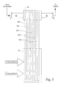
FIGURE 3 illustrates key elements of a system used to remove heat from cooling air that is used to cool a turbine engine. - A diagram of the major elements of a turbine engine are illustrated in
FIGURE 1 . The turbine engine includes acompressor section 20 and aturbine section 40. Rotating elements within thecompressor 20 and theturbine 40 are connected to a rotatingshaft 32. - Compressed air received from the
compressor 20 is combined with fuel in thecombustors combustors turbine 40. - The hot combustion gases provided to the
turbine section 40 flow across nozzles and other hot path components within the turbine. The nozzles direct the hot combustion gases toward the turbine blades at an optimum angle, and the combustion gases cause the turbine blades to rotate theshaft 32 of the turbine engine. The hot combustion gases are at extremely high temperatures, and the high temperature gases tend to cause deterioration of the hot path components within the turbine. - To help the components within the
turbine 40 withstand the extremely high temperatures of the hot combustion gases, cooling air is provided to theturbine 40. As shown inFIGURE 1 , acooling air duct 50 takes air from thecompressor section 20 and passes it to theturbine section 40. One ormore valves 52 may be located in thecooling air duct 50 to control the flow of cooling air from thecompressor 20 to theturbine 40. -
FIGURE 2 illustrates an embodiment where a plurality ofheat pipes FIGURE 2 , first ends of the heat pipes receive or remove heat from the flow of air passing through thecooling air duct 50. The heat is then transferred to second ends of the heat pipes. The heat absorbed from the flow of air passing through thecooling duct 50 can then be removed from the second ends of the heat pipes. In some embodiments, the heat can be rejected to ambient air. In other embodiments, the heat removed from the heat pipes could be used for another secondary purpose. For example, it is known to use the heat removed from a flow of cooling air to heat fuel which is burned in the turbine engine, to reheat steam used as part of a power production process, or for other beneficial purposes. - When heat is removed from the flow of air passing through the cooling air duct, the cooling air delivered to the turbine is at a lower temperature, which enhances the cooling effect. This allows the same volume of cooling air to better cool the elements in the turbine. Alternatively, the same degree of cooling of the turbine could be achieved with a lesser volume of air from the compressor if the heat pipes are used to cool the air before it is delivered to the turbine.
- As known to those of ordinary skill in the art, a heat pipe typically includes a sealed pipe with a fluid inside. When a first end of the heat pipe is heated, fluid at the first end evaporates and the vapor flows to the second end of the heat pipe. When the vapor flows to the second end of the heat pipe it condenses, which releases the heat which originally caused the fluid to vaporize. This vaporization and condensation process tends to create a continuous flow of the material within the heat pipe, which efficiently transfers heat from the first end of the pipe to the second end of the pipe.
- An alternative type of heat pipe, known as an inorganic material coated heat pipe (IMCHP), does not use a fluid/vapor material to transfer heat from one end of the pipe to the other. In an inorganic material coated heat pipe, the inner surfaces of the pipe are coated with a special heat conducting material. Vapor is removed from within the pipe to create a vacuum inside the pipe. The pipe is then permanently sealed. The special heat conducting inorganic material located on the inner surfaces of the heat pipe transfers heat from one end of the pipe to the other. An inorganic material coated heat pipe can provide faster transfer of heat from one end to the other than more traditional heat pipes.
- Individual embodiments of the invention could make use of a heat pipe containing a fluid, an inorganic material coated heat pipe, or any other type of thermal management device.
-
FIGURE 3 illustrates one embodiment of a system that removes heat from a flow of air that is to be provided to the turbine of an engine. As shown inFIGURE 3 , a flow of cooling air received from a compressor would be communicated through acooling air duct 50. First ends of the plurality ofheat pipes cooling air duct 50 flows over the first ends of the heat pipes. This would allow the first ends of the heat pipes to absorb heat from the flow of air passing through thecooling air duct 50. - In the embodiment shown in
FIGURE 3 , the second ends of the heat pipes are located in aheat exchanger 70, and a flow of ambient air or some other cooling media passes across the second ends of the heat pipes to remove heat from the second ends of the heat pipes. The flow of coolant passing through theheat exchanger 70 could be ambient air, fuel gas, cooling water, or some other type of media. - In alternate embodiments of the invention, heat could be removed from the second ends of the heat pipes using a different type of
heat exchanger 70. For instance a flow of a liquid or a gas through theheat exchanger 70 could also be used to remove heat from the second ends of the heat pipes. In still other embodiments, the second ends of the heat pipes could be embedded in a solid heat conducting material, and the solid heat conducting material could be placed in a liquid or gas flow that serves to remove heat from the second ends of the heat pipes. - Also, as described above, the heat removed from the second ends of the heat pipes could be used for a beneficial purpose. In that instance, the way in which heat is removed from the second ends of the heat pipes could depend on the purpose to which the heat energy is being put. For example, the thermal energy could be used to power an absorption chiller to provide cooling to a building.
- In the embodiment illustrated in
FIGURE 3 , the first ends of the heat pipes are simply shown as being located in the flow of air passing through thecooling air duct 50. In some embodiments, aheat exchanger unit 60 could be used to transfer heat from the flow of air passing through thecooling air duct 50 into the first ends of the heat pipes. Thisheat exchanger unit 60 could include a secondary fluid or a secondary gas to facilitate the transfer of heat from the flow of air passing through the cooling duct to the first ends of the heat pipes. In still other embodiments, the first ends of the heat pipes could be mounted in a solid heat conducting material, and the solid material could then be placed in the flow of air passing through thecooling air duct 50. - In still other alternate embodiments, cooling fins could be arranged on either or both ends of the heat pipes. Cooling fins on the first ends of the heat pipes would facilitate the transfer of heat from the air passing through the cooling air duct into the heat pipes. Likewise, fins on the second ends of the heat pipes would facilitate the transfer of heat out of the heat pipes and into ambient air or some other medium.
- While the invention has been described in connection with what is presently considered to be the most practical and preferred embodiment, it is to be understood that the invention is not to be limited to the disclosed embodiment, but on the contrary, is intended to cover various modifications and equivalent arrangements included within the scope of the appended claims.
- For completeness, various aspects of the invention are now set out in the following numbered clauses:
- 1. A heat transfer system for a turbine engine, comprising:
- a cooling air duct connected between a compressor and at least one turbine stage of the turbine engine; and
- a plurality of heat pipes having first ends mounted in the cooling air duct, wherein the heat pipes conduct heat away from a flow of air passing through the cooling air duct.
- 2. The heat transfer system of clause 1, wherein the cooling air duct receives a flow of air from the compressor and delivers the flow of air to the at least one turbine stage of the turbine engine to cool the at least one turbine stage.
- 3. The heat transfer system of clause 1, wherein second ends of the heat pipes are located at a position that allows heat to be removed from the second ends of the heat pipes.
- 4. The heat transfer system of clause 1, further comprising a heat transfer unit coupled to second ends of the heat pipes, wherein heat from the flow of air passing through the cooling air duct which is transferred into the first ends of the heat pipes is removed from the second ends of the heat pipes by the heat transfer unit.
- 5. The heat transfer system of clause 4, wherein a flow of coolant passes through the heat transfer unit, and wherein heat is removed from the second ends of the heat pipes by the flow of coolant passing through the heat transfer unit.
- 6. The heat transfer system of clause 1, wherein the cooling air duct delivers cooling air to at least one of a second and a third wheelspace of the turbine of the turbine engine.
- 7. A heat transfer system for a turbine engine, comprising:
- a cooling air duct connected between a compressor and at least one turbine stage of the turbine engine;
- a first heat transfer unit coupled to the cooling air duct; and
- a plurality of heat pipes having first ends coupled to the first heat transfer unit,
- wherein the first heat transfer unit transfers heat from a flow of air passing through the cooling air duct into the first ends of the heat pipes.
- 8. The heat transfer system of clause 7, wherein the cooling air duct receives a flow of air from the compressor and delivers the flow of air to the at least one turbine stage of the turbine engine to cool the at least one turbine stage.
- 9. The heat transfer system of clause 7, wherein second ends of the heat pipes are located at a position that allows heat to be removed from the second ends of the heat pipes.
- 10. The heat transfer system of clause 7, further comprising a second heat transfer unit coupled to second ends of the heat pipes, wherein heat from the flow of air passing through the cooling air duct which is transferred into the first ends of the heat pipes is removed from the second ends of the heat pipes by the second heat transfer unit.
- 11. The heat transfer system of
clause 10, wherein a flow of coolant passes through the second heat transfer unit, and wherein heat is removed from the second ends of the heat pipes by the flow of ambient air passing through the second heat transfer unit. - 12. A method of cooling a turbine of a turbine engine, comprising:
- removing a flow of air from a compressor of the turbine engine;
- removing heat from the flow of air with a plurality of heat pipes to create a flow of cooled air; and
- cooling the turbine of the turbine engine with the flow of cooled air.
- 13. The method of clause 12, wherein the step of removing heat from the flow of air comprises passing the flow of air across first ends of the plurality of heat pipes.
- 14. The method of clause 13, further comprising removing heat from second ends of the plurality of heat pipes.
- 15. The method of clause 14, wherein the step of removing heat from the second ends of the plurality of heat pipes comprises transferring heat from the second ends of the plurality of heat pipes to a coolant.
- 16. The method of clause 12, wherein the cooling step comprises delivering the flow of cooled air to at least one of the second and third wheelspaces of the turbine engine.
Claims (15)
- A heat transfer system for a turbine engine, comprising:a cooling air duct connected between a compressor and at least one turbine stage of the turbine engine; anda plurality of heat pipes having first ends mounted in the cooling air duct, wherein the heat pipes conduct heat away from a flow of air passing through the cooling air duct.
- The heat transfer system of claim 1, wherein the cooling air duct receives a flow of air from the compressor and delivers the flow of air to the at least one turbine stage of the turbine engine to cool the at least one turbine stage.
- The heat transfer system of claim 1 or 2, wherein second ends of the heat pipes are located at a position that allows heat to be removed from the second ends of the heat pipes.
- The heat transfer system of any of the preceding claims, further comprising a heat transfer unit coupled to second ends of the heat pipes, wherein heat from the flow of air passing through the cooling air duct which is transferred into the first ends of the heat pipes is removed from the second ends of the heat pipes by the heat transfer unit.
- The heat transfer system of claim 4, wherein a flow of coolant passes through the heat transfer unit, and wherein heat is removed from the second ends of the heat pipes by the flow of coolant passing through the heat transfer unit.
- The heat transfer system of any of the preceding claims, wherein the cooling air duct delivers cooling air to at least one of a second and a third wheelspace of the turbine of the turbine engine.
- A method of cooling a turbine of a turbine engine, comprising:removing a flow of air from a compressor of the turbine engine;removing heat from the flow of air with a plurality of heat pipes to create a flow of cooled air; andcooling the turbine of the turbine engine with the flow of cooled air.
- The method of claim 7, wherein the step of removing heat from the flow of air comprises passing the flow of air across first ends of the plurality of heat pipes.
- The method of claim 8, further comprising removing heat from second ends of the plurality of heat pipes.
- The method of claim 9, wherein the step of removing heat from the second ends of the plurality of heat pipes comprises transferring heat from the second ends of the plurality of heat pipes to a coolant.
- The method of any of claims 7 to 10, wherein the cooling step comprises delivering the flow of cooled air to at least one of the second and third wheelspaces of the turbine engine.
- A heat transfer system for a turbine engine, comprising:a cooling air duct connected between a compressor and at least one turbine stage of the turbine engine;a first heat transfer unit coupled to the cooling air duct; anda plurality of heat pipes having first ends coupled to the first heat transfer unit,wherein the first heat transfer unit transfers heat from a flow of air passing through the cooling air duct into the first ends of the heat pipes.
- The heat transfer system of claim 12, wherein the cooling air duct receives a flow of air from the compressor and delivers the flow of air to the at least one turbine stage of the turbine engine to cool the at least one turbine stage.
- The heat transfer system of claim 12 or 13, wherein second ends of the heat pipes are located at a position that allows heat to be removed from the second ends of the heat pipes.
- The heat transfer system of any of claims 12 to 14, further comprising a second heat transfer unit coupled to second ends of the heat pipes, wherein heat from the flow of air passing through the cooling air duct which is transferred into the first ends of the heat pipes is removed from the second ends of the heat pipes by the second heat transfer unit.
Applications Claiming Priority (1)
| Application Number | Priority Date | Filing Date | Title |
|---|---|---|---|
| US12/425,416 US8112998B2 (en) | 2009-04-17 | 2009-04-17 | Apparatus and method for cooling a turbine using heat pipes |
Publications (3)
| Publication Number | Publication Date |
|---|---|
| EP2241728A2 true EP2241728A2 (en) | 2010-10-20 |
| EP2241728A3 EP2241728A3 (en) | 2012-08-08 |
| EP2241728B1 EP2241728B1 (en) | 2015-03-25 |
Family
ID=42214341
Family Applications (1)
| Application Number | Title | Priority Date | Filing Date |
|---|---|---|---|
| EP10160136.7A Not-in-force EP2241728B1 (en) | 2009-04-17 | 2010-04-16 | Apparatus and method for cooling a turbine using heat pipes |
Country Status (4)
| Country | Link |
|---|---|
| US (1) | US8112998B2 (en) |
| EP (1) | EP2241728B1 (en) |
| JP (1) | JP5825759B2 (en) |
| CN (1) | CN101929389B (en) |
Cited By (3)
| Publication number | Priority date | Publication date | Assignee | Title |
|---|---|---|---|---|
| WO2016160023A1 (en) * | 2015-04-02 | 2016-10-06 | General Electric Company | Heat pipe temperature management system for wheels and buckets in a turbomachine |
| US9797310B2 (en) | 2015-04-02 | 2017-10-24 | General Electric Company | Heat pipe temperature management system for a turbomachine |
| EP3872304A1 (en) | 2020-02-27 | 2021-09-01 | Airbus Operations | Regulation system comprising a valve, a regulator, an actuator and a cooling system using heat pipes |
Families Citing this family (9)
| Publication number | Priority date | Publication date | Assignee | Title |
|---|---|---|---|---|
| US9541008B2 (en) | 2012-02-06 | 2017-01-10 | General Electric Company | Method and apparatus to control part-load performance of a turbine |
| US8725384B2 (en) | 2012-02-10 | 2014-05-13 | General Electic Company | Detection system and method to detect flame holding event |
| KR101427924B1 (en) | 2012-11-21 | 2014-08-11 | 현대자동차 주식회사 | Cooling device of compressed air in fuel cell system |
| US20160290174A1 (en) * | 2015-04-02 | 2016-10-06 | General Electric Company | Heat pipe aftercooling system for a turbomachine |
| US20160290235A1 (en) * | 2015-04-02 | 2016-10-06 | General Electric Company | Heat pipe temperature management system for a turbomachine |
| US20160290232A1 (en) * | 2015-04-02 | 2016-10-06 | General Electric Company | Heat pipe cooling system for a turbomachine |
| US20160290231A1 (en) * | 2015-04-02 | 2016-10-06 | General Electric Company | Heat pipe intercooling system for a turbomachine |
| US20160353613A1 (en) * | 2015-05-27 | 2016-12-01 | Quanta Computer Inc. | Hybrid cooling for computer systems |
| US11168583B2 (en) | 2016-07-22 | 2021-11-09 | General Electric Company | Systems and methods for cooling components within a gas turbine engine |
Family Cites Families (19)
| Publication number | Priority date | Publication date | Assignee | Title |
|---|---|---|---|---|
| US3429122A (en) * | 1966-11-07 | 1969-02-25 | Martin Marietta Corp | Heat pipe regenerator for gas turbine engines |
| DE1951356C3 (en) * | 1969-10-11 | 1980-08-28 | Mtu Motoren- Und Turbinen-Union Muenchen Gmbh, 8000 Muenchen | Gas turbine engine for aircraft |
| US4045197A (en) * | 1976-09-08 | 1977-08-30 | Ppg Industries, Inc. | Glassmaking furnace employing heat pipes for preheating glass batch |
| US4313795A (en) * | 1980-03-10 | 1982-02-02 | Dauvergne Hector A | Nuclear power plant with on-site storage capabilities |
| US4315893A (en) * | 1980-12-17 | 1982-02-16 | Foster Wheeler Energy Corporation | Reformer employing finned heat pipes |
| US5255505A (en) * | 1992-02-21 | 1993-10-26 | Westinghouse Electric Corp. | System for capturing heat transferred from compressed cooling air in a gas turbine |
| US5267608A (en) * | 1992-07-27 | 1993-12-07 | General Electric Company | Heat exchanger and reactor for aircraft and propulsion systems |
| US6098395A (en) * | 1996-04-04 | 2000-08-08 | Siemens Westinghouse Power Corporation | Closed-loop air cooling system for a turbine engine |
| JPH1193694A (en) * | 1997-09-18 | 1999-04-06 | Toshiba Corp | Gas turbine plant |
| JP2000328962A (en) * | 1999-05-19 | 2000-11-28 | Mitsubishi Heavy Ind Ltd | Turbine system |
| JP3652962B2 (en) * | 1999-11-25 | 2005-05-25 | 三菱重工業株式会社 | Gas turbine combined cycle |
| GB2389174B (en) * | 2002-05-01 | 2005-10-26 | Rolls Royce Plc | Cooling systems |
| US20070022732A1 (en) * | 2005-06-22 | 2007-02-01 | General Electric Company | Methods and apparatus for operating gas turbine engines |
| US7581401B2 (en) * | 2005-09-15 | 2009-09-01 | General Electric Company | Methods and apparatus for cooling gas turbine engine components |
| IL177383A (en) * | 2006-08-09 | 2016-02-29 | Hirshberg Israel | Device for cooling air |
| US7845159B2 (en) * | 2006-08-31 | 2010-12-07 | General Electric Company | Heat pipe-based cooling apparatus and method for turbine engine |
| US7823374B2 (en) * | 2006-08-31 | 2010-11-02 | General Electric Company | Heat transfer system and method for turbine engine using heat pipes |
| US8127547B2 (en) * | 2007-06-07 | 2012-03-06 | United Technologies Corporation | Gas turbine engine with air and fuel cooling system |
| US8056345B2 (en) * | 2007-06-13 | 2011-11-15 | United Technologies Corporation | Hybrid cooling of a gas turbine engine |
-
2009
- 2009-04-17 US US12/425,416 patent/US8112998B2/en not_active Expired - Fee Related
-
2010
- 2010-04-13 JP JP2010091881A patent/JP5825759B2/en not_active Expired - Fee Related
- 2010-04-15 CN CN201010167508.2A patent/CN101929389B/en not_active Expired - Fee Related
- 2010-04-16 EP EP10160136.7A patent/EP2241728B1/en not_active Not-in-force
Non-Patent Citations (1)
| Title |
|---|
| None |
Cited By (6)
| Publication number | Priority date | Publication date | Assignee | Title |
|---|---|---|---|---|
| WO2016160023A1 (en) * | 2015-04-02 | 2016-10-06 | General Electric Company | Heat pipe temperature management system for wheels and buckets in a turbomachine |
| US9797310B2 (en) | 2015-04-02 | 2017-10-24 | General Electric Company | Heat pipe temperature management system for a turbomachine |
| US10598094B2 (en) | 2015-04-02 | 2020-03-24 | General Electric Company | Heat pipe temperature management system for wheels and buckets in a turbomachine |
| EP3872304A1 (en) | 2020-02-27 | 2021-09-01 | Airbus Operations | Regulation system comprising a valve, a regulator, an actuator and a cooling system using heat pipes |
| FR3107732A1 (en) * | 2020-02-27 | 2021-09-03 | Airbus Operations | REGULATION SYSTEM INCLUDING A VALVE, A REGULATOR, AN ACTUATOR AND A COOLING SYSTEM USING HEAT PIPE TUBES |
| US11391220B2 (en) | 2020-02-27 | 2022-07-19 | Airbus Operations Sas | Regulation system comprising a valve, a regulator, an actuator and a cooling system using heat pipes |
Also Published As
| Publication number | Publication date |
|---|---|
| CN101929389B (en) | 2015-12-02 |
| JP5825759B2 (en) | 2015-12-02 |
| EP2241728A3 (en) | 2012-08-08 |
| JP2010249137A (en) | 2010-11-04 |
| US8112998B2 (en) | 2012-02-14 |
| EP2241728B1 (en) | 2015-03-25 |
| CN101929389A (en) | 2010-12-29 |
| US20100263350A1 (en) | 2010-10-21 |
Similar Documents
| Publication | Publication Date | Title |
|---|---|---|
| EP2241728A2 (en) | Apparatus and method for cooling a turbine using heat pipes | |
| US9797310B2 (en) | Heat pipe temperature management system for a turbomachine | |
| CN101629516B (en) | For removing the heat pipe of heat energy from waste gas | |
| US8127547B2 (en) | Gas turbine engine with air and fuel cooling system | |
| EP3075985A1 (en) | Heat pipe cooled turbine casing system for clearance management | |
| US20080053099A1 (en) | Heat pipe-based cooling apparatus and method for turbine engine | |
| US20160290235A1 (en) | Heat pipe temperature management system for a turbomachine | |
| RU2613100C2 (en) | Gas turbine (versions) and method of gas turbine operation | |
| JP2007064228A (en) | Device for operating a gas turbine engine | |
| US20100054926A1 (en) | System and method for thermal management of a gas turbine inlet | |
| SI24856A (en) | Method and device for using low-temperature sources of cogeneration systems with high-temperature heat pump according to the water / water concept | |
| CN102536464A (en) | Heat exchanger for a combined cycle power plant | |
| RU2011152029A (en) | HEAT RECOVERY DEVICE | |
| JP6074504B2 (en) | Intercooler heat exchanger and water extraction device | |
| TR201901543T4 (en) | Gas turbine exhaust gas cooling system. | |
| CN106761950A (en) | A kind of hot plate samming is without blending turbine blade cooling device and method | |
| RU121562U1 (en) | ABC GI AIR CONDENSER START-UP SYSTEM WITH NEGATIVE AIR TEMPERATURES | |
| CN107289665A (en) | Regional Energy supply system | |
| KR101854341B1 (en) | Burn-Off Unit with Emitting Combusted Oil Vapor, Debris and Thinner by Jet Fan During Heat Treatment | |
| CN220451997U (en) | Energy recovery system applied to direct air cooling unit | |
| CN207350743U (en) | A kind of turbulent flow cold and heat recovery device | |
| RU2472020C2 (en) | Regenerative heat exchanger built into gas-turbine plant | |
| RU2362890C2 (en) | Steam-and-gas turbo-installation | |
| CN108826339A (en) | It is a kind of white plume administer and energy recycling system and its method | |
| RU141859U1 (en) | HEAT EXCHANGE BLOCK |
Legal Events
| Date | Code | Title | Description |
|---|---|---|---|
| PUAI | Public reference made under article 153(3) epc to a published international application that has entered the european phase |
Free format text: ORIGINAL CODE: 0009012 |
|
| AK | Designated contracting states |
Kind code of ref document: A2 Designated state(s): AT BE BG CH CY CZ DE DK EE ES FI FR GB GR HR HU IE IS IT LI LT LU LV MC MK MT NL NO PL PT RO SE SI SK SM TR |
|
| AX | Request for extension of the european patent |
Extension state: AL BA ME RS |
|
| PUAL | Search report despatched |
Free format text: ORIGINAL CODE: 0009013 |
|
| AK | Designated contracting states |
Kind code of ref document: A3 Designated state(s): AT BE BG CH CY CZ DE DK EE ES FI FR GB GR HR HU IE IS IT LI LT LU LV MC MK MT NL NO PL PT RO SE SI SK SM TR |
|
| AX | Request for extension of the european patent |
Extension state: AL BA ME RS |
|
| RIC1 | Information provided on ipc code assigned before grant |
Ipc: F01D 25/12 20060101AFI20120629BHEP Ipc: F02C 7/18 20060101ALI20120629BHEP Ipc: F02C 7/12 20060101ALI20120629BHEP |
|
| 17P | Request for examination filed |
Effective date: 20130208 |
|
| 17Q | First examination report despatched |
Effective date: 20130523 |
|
| GRAP | Despatch of communication of intention to grant a patent |
Free format text: ORIGINAL CODE: EPIDOSNIGR1 |
|
| INTG | Intention to grant announced |
Effective date: 20141024 |
|
| GRAS | Grant fee paid |
Free format text: ORIGINAL CODE: EPIDOSNIGR3 |
|
| GRAA | (expected) grant |
Free format text: ORIGINAL CODE: 0009210 |
|
| AK | Designated contracting states |
Kind code of ref document: B1 Designated state(s): AT BE BG CH CY CZ DE DK EE ES FI FR GB GR HR HU IE IS IT LI LT LU LV MC MK MT NL NO PL PT RO SE SI SK SM TR |
|
| REG | Reference to a national code |
Ref country code: GB Ref legal event code: FG4D |
|
| REG | Reference to a national code |
Ref country code: CH Ref legal event code: EP |
|
| REG | Reference to a national code |
Ref country code: IE Ref legal event code: FG4D |
|
| REG | Reference to a national code |
Ref country code: DE Ref legal event code: R096 Ref document number: 602010023328 Country of ref document: DE Effective date: 20150507 |
|
| REG | Reference to a national code |
Ref country code: AT Ref legal event code: REF Ref document number: 718014 Country of ref document: AT Kind code of ref document: T Effective date: 20150515 |
|
| PG25 | Lapsed in a contracting state [announced via postgrant information from national office to epo] |
Ref country code: SE Free format text: LAPSE BECAUSE OF FAILURE TO SUBMIT A TRANSLATION OF THE DESCRIPTION OR TO PAY THE FEE WITHIN THE PRESCRIBED TIME-LIMIT Effective date: 20150325 Ref country code: NO Free format text: LAPSE BECAUSE OF FAILURE TO SUBMIT A TRANSLATION OF THE DESCRIPTION OR TO PAY THE FEE WITHIN THE PRESCRIBED TIME-LIMIT Effective date: 20150625 Ref country code: HR Free format text: LAPSE BECAUSE OF FAILURE TO SUBMIT A TRANSLATION OF THE DESCRIPTION OR TO PAY THE FEE WITHIN THE PRESCRIBED TIME-LIMIT Effective date: 20150325 Ref country code: FI Free format text: LAPSE BECAUSE OF FAILURE TO SUBMIT A TRANSLATION OF THE DESCRIPTION OR TO PAY THE FEE WITHIN THE PRESCRIBED TIME-LIMIT Effective date: 20150325 Ref country code: LT Free format text: LAPSE BECAUSE OF FAILURE TO SUBMIT A TRANSLATION OF THE DESCRIPTION OR TO PAY THE FEE WITHIN THE PRESCRIBED TIME-LIMIT Effective date: 20150325 |
|
| REG | Reference to a national code |
Ref country code: AT Ref legal event code: MK05 Ref document number: 718014 Country of ref document: AT Kind code of ref document: T Effective date: 20150325 |
|
| REG | Reference to a national code |
Ref country code: LT Ref legal event code: MG4D |
|
| PG25 | Lapsed in a contracting state [announced via postgrant information from national office to epo] |
Ref country code: GR Free format text: LAPSE BECAUSE OF FAILURE TO SUBMIT A TRANSLATION OF THE DESCRIPTION OR TO PAY THE FEE WITHIN THE PRESCRIBED TIME-LIMIT Effective date: 20150626 Ref country code: LV Free format text: LAPSE BECAUSE OF FAILURE TO SUBMIT A TRANSLATION OF THE DESCRIPTION OR TO PAY THE FEE WITHIN THE PRESCRIBED TIME-LIMIT Effective date: 20150325 |
|
| PG25 | Lapsed in a contracting state [announced via postgrant information from national office to epo] |
Ref country code: NL Free format text: LAPSE BECAUSE OF FAILURE TO SUBMIT A TRANSLATION OF THE DESCRIPTION OR TO PAY THE FEE WITHIN THE PRESCRIBED TIME-LIMIT Effective date: 20150325 |
|
| PG25 | Lapsed in a contracting state [announced via postgrant information from national office to epo] |
Ref country code: RO Free format text: LAPSE BECAUSE OF FAILURE TO SUBMIT A TRANSLATION OF THE DESCRIPTION OR TO PAY THE FEE WITHIN THE PRESCRIBED TIME-LIMIT Effective date: 20150325 Ref country code: PT Free format text: LAPSE BECAUSE OF FAILURE TO SUBMIT A TRANSLATION OF THE DESCRIPTION OR TO PAY THE FEE WITHIN THE PRESCRIBED TIME-LIMIT Effective date: 20150727 Ref country code: EE Free format text: LAPSE BECAUSE OF FAILURE TO SUBMIT A TRANSLATION OF THE DESCRIPTION OR TO PAY THE FEE WITHIN THE PRESCRIBED TIME-LIMIT Effective date: 20150325 Ref country code: ES Free format text: LAPSE BECAUSE OF FAILURE TO SUBMIT A TRANSLATION OF THE DESCRIPTION OR TO PAY THE FEE WITHIN THE PRESCRIBED TIME-LIMIT Effective date: 20150325 Ref country code: CZ Free format text: LAPSE BECAUSE OF FAILURE TO SUBMIT A TRANSLATION OF THE DESCRIPTION OR TO PAY THE FEE WITHIN THE PRESCRIBED TIME-LIMIT Effective date: 20150325 Ref country code: SK Free format text: LAPSE BECAUSE OF FAILURE TO SUBMIT A TRANSLATION OF THE DESCRIPTION OR TO PAY THE FEE WITHIN THE PRESCRIBED TIME-LIMIT Effective date: 20150325 |
|
| PG25 | Lapsed in a contracting state [announced via postgrant information from national office to epo] |
Ref country code: IS Free format text: LAPSE BECAUSE OF FAILURE TO SUBMIT A TRANSLATION OF THE DESCRIPTION OR TO PAY THE FEE WITHIN THE PRESCRIBED TIME-LIMIT Effective date: 20150725 Ref country code: MC Free format text: LAPSE BECAUSE OF FAILURE TO SUBMIT A TRANSLATION OF THE DESCRIPTION OR TO PAY THE FEE WITHIN THE PRESCRIBED TIME-LIMIT Effective date: 20150325 Ref country code: AT Free format text: LAPSE BECAUSE OF FAILURE TO SUBMIT A TRANSLATION OF THE DESCRIPTION OR TO PAY THE FEE WITHIN THE PRESCRIBED TIME-LIMIT Effective date: 20150325 Ref country code: PL Free format text: LAPSE BECAUSE OF FAILURE TO SUBMIT A TRANSLATION OF THE DESCRIPTION OR TO PAY THE FEE WITHIN THE PRESCRIBED TIME-LIMIT Effective date: 20150325 |
|
| REG | Reference to a national code |
Ref country code: DE Ref legal event code: R097 Ref document number: 602010023328 Country of ref document: DE |
|
| REG | Reference to a national code |
Ref country code: IE Ref legal event code: MM4A |
|
| PG25 | Lapsed in a contracting state [announced via postgrant information from national office to epo] |
Ref country code: IT Free format text: LAPSE BECAUSE OF FAILURE TO SUBMIT A TRANSLATION OF THE DESCRIPTION OR TO PAY THE FEE WITHIN THE PRESCRIBED TIME-LIMIT Effective date: 20150325 Ref country code: DK Free format text: LAPSE BECAUSE OF FAILURE TO SUBMIT A TRANSLATION OF THE DESCRIPTION OR TO PAY THE FEE WITHIN THE PRESCRIBED TIME-LIMIT Effective date: 20150325 |
|
| PLBE | No opposition filed within time limit |
Free format text: ORIGINAL CODE: 0009261 |
|
| REG | Reference to a national code |
Ref country code: FR Ref legal event code: ST Effective date: 20151231 |
|
| STAA | Information on the status of an ep patent application or granted ep patent |
Free format text: STATUS: NO OPPOSITION FILED WITHIN TIME LIMIT |
|
| GBPC | Gb: european patent ceased through non-payment of renewal fee |
Effective date: 20150625 |
|
| PG25 | Lapsed in a contracting state [announced via postgrant information from national office to epo] |
Ref country code: FR Free format text: LAPSE BECAUSE OF NON-PAYMENT OF DUE FEES Effective date: 20150526 |
|
| 26N | No opposition filed |
Effective date: 20160105 |
|
| PG25 | Lapsed in a contracting state [announced via postgrant information from national office to epo] |
Ref country code: GB Free format text: LAPSE BECAUSE OF NON-PAYMENT OF DUE FEES Effective date: 20150625 Ref country code: IE Free format text: LAPSE BECAUSE OF NON-PAYMENT OF DUE FEES Effective date: 20150416 |
|
| PG25 | Lapsed in a contracting state [announced via postgrant information from national office to epo] |
Ref country code: SI Free format text: LAPSE BECAUSE OF FAILURE TO SUBMIT A TRANSLATION OF THE DESCRIPTION OR TO PAY THE FEE WITHIN THE PRESCRIBED TIME-LIMIT Effective date: 20150325 |
|
| PG25 | Lapsed in a contracting state [announced via postgrant information from national office to epo] |
Ref country code: BE Free format text: LAPSE BECAUSE OF FAILURE TO SUBMIT A TRANSLATION OF THE DESCRIPTION OR TO PAY THE FEE WITHIN THE PRESCRIBED TIME-LIMIT Effective date: 20150325 |
|
| PG25 | Lapsed in a contracting state [announced via postgrant information from national office to epo] |
Ref country code: MT Free format text: LAPSE BECAUSE OF FAILURE TO SUBMIT A TRANSLATION OF THE DESCRIPTION OR TO PAY THE FEE WITHIN THE PRESCRIBED TIME-LIMIT Effective date: 20150325 |
|
| PG25 | Lapsed in a contracting state [announced via postgrant information from national office to epo] |
Ref country code: SM Free format text: LAPSE BECAUSE OF FAILURE TO SUBMIT A TRANSLATION OF THE DESCRIPTION OR TO PAY THE FEE WITHIN THE PRESCRIBED TIME-LIMIT Effective date: 20150325 Ref country code: HU Free format text: LAPSE BECAUSE OF FAILURE TO SUBMIT A TRANSLATION OF THE DESCRIPTION OR TO PAY THE FEE WITHIN THE PRESCRIBED TIME-LIMIT; INVALID AB INITIO Effective date: 20100416 Ref country code: BG Free format text: LAPSE BECAUSE OF FAILURE TO SUBMIT A TRANSLATION OF THE DESCRIPTION OR TO PAY THE FEE WITHIN THE PRESCRIBED TIME-LIMIT Effective date: 20150325 |
|
| PG25 | Lapsed in a contracting state [announced via postgrant information from national office to epo] |
Ref country code: CY Free format text: LAPSE BECAUSE OF FAILURE TO SUBMIT A TRANSLATION OF THE DESCRIPTION OR TO PAY THE FEE WITHIN THE PRESCRIBED TIME-LIMIT Effective date: 20150325 |
|
| PG25 | Lapsed in a contracting state [announced via postgrant information from national office to epo] |
Ref country code: TR Free format text: LAPSE BECAUSE OF FAILURE TO SUBMIT A TRANSLATION OF THE DESCRIPTION OR TO PAY THE FEE WITHIN THE PRESCRIBED TIME-LIMIT Effective date: 20150325 |
|
| PG25 | Lapsed in a contracting state [announced via postgrant information from national office to epo] |
Ref country code: LU Free format text: LAPSE BECAUSE OF NON-PAYMENT OF DUE FEES Effective date: 20150416 |
|
| PG25 | Lapsed in a contracting state [announced via postgrant information from national office to epo] |
Ref country code: MK Free format text: LAPSE BECAUSE OF FAILURE TO SUBMIT A TRANSLATION OF THE DESCRIPTION OR TO PAY THE FEE WITHIN THE PRESCRIBED TIME-LIMIT Effective date: 20150325 |
|
| PGFP | Annual fee paid to national office [announced via postgrant information from national office to epo] |
Ref country code: CH Payment date: 20180502 Year of fee payment: 9 Ref country code: DE Payment date: 20180427 Year of fee payment: 9 |
|
| REG | Reference to a national code |
Ref country code: DE Ref legal event code: R119 Ref document number: 602010023328 Country of ref document: DE |
|
| REG | Reference to a national code |
Ref country code: CH Ref legal event code: PL |
|
| PG25 | Lapsed in a contracting state [announced via postgrant information from national office to epo] |
Ref country code: CH Free format text: LAPSE BECAUSE OF NON-PAYMENT OF DUE FEES Effective date: 20190430 Ref country code: LI Free format text: LAPSE BECAUSE OF NON-PAYMENT OF DUE FEES Effective date: 20190430 Ref country code: DE Free format text: LAPSE BECAUSE OF NON-PAYMENT OF DUE FEES Effective date: 20191101 |