EP2241723A1 - Turbine blade-cascade end wall - Google Patents
Turbine blade-cascade end wall Download PDFInfo
- Publication number
- EP2241723A1 EP2241723A1 EP08872470A EP08872470A EP2241723A1 EP 2241723 A1 EP2241723 A1 EP 2241723A1 EP 08872470 A EP08872470 A EP 08872470A EP 08872470 A EP08872470 A EP 08872470A EP 2241723 A1 EP2241723 A1 EP 2241723A1
- Authority
- EP
- European Patent Office
- Prior art keywords
- turbine
- blade
- blades
- stationary blade
- stationary
- Prior art date
- Legal status (The legal status is an assumption and is not a legal conclusion. Google has not performed a legal analysis and makes no representation as to the accuracy of the status listed.)
- Granted
Links
Images


Classifications
-
- F—MECHANICAL ENGINEERING; LIGHTING; HEATING; WEAPONS; BLASTING
- F01—MACHINES OR ENGINES IN GENERAL; ENGINE PLANTS IN GENERAL; STEAM ENGINES
- F01D—NON-POSITIVE DISPLACEMENT MACHINES OR ENGINES, e.g. STEAM TURBINES
- F01D9/00—Stators
- F01D9/02—Nozzles; Nozzle boxes; Stator blades; Guide conduits, e.g. individual nozzles
- F01D9/04—Nozzles; Nozzle boxes; Stator blades; Guide conduits, e.g. individual nozzles forming ring or sector
- F01D9/041—Nozzles; Nozzle boxes; Stator blades; Guide conduits, e.g. individual nozzles forming ring or sector using blades
-
- F—MECHANICAL ENGINEERING; LIGHTING; HEATING; WEAPONS; BLASTING
- F01—MACHINES OR ENGINES IN GENERAL; ENGINE PLANTS IN GENERAL; STEAM ENGINES
- F01D—NON-POSITIVE DISPLACEMENT MACHINES OR ENGINES, e.g. STEAM TURBINES
- F01D5/00—Blades; Blade-carrying members; Heating, heat-insulating, cooling or antivibration means on the blades or the members
- F01D5/12—Blades
- F01D5/14—Form or construction
- F01D5/141—Shape, i.e. outer, aerodynamic form
-
- F—MECHANICAL ENGINEERING; LIGHTING; HEATING; WEAPONS; BLASTING
- F01—MACHINES OR ENGINES IN GENERAL; ENGINE PLANTS IN GENERAL; STEAM ENGINES
- F01D—NON-POSITIVE DISPLACEMENT MACHINES OR ENGINES, e.g. STEAM TURBINES
- F01D5/00—Blades; Blade-carrying members; Heating, heat-insulating, cooling or antivibration means on the blades or the members
- F01D5/12—Blades
- F01D5/14—Form or construction
- F01D5/141—Shape, i.e. outer, aerodynamic form
- F01D5/142—Shape, i.e. outer, aerodynamic form of the blades of successive rotor or stator blade-rows
- F01D5/143—Contour of the outer or inner working fluid flow path wall, i.e. shroud or hub contour
-
- F—MECHANICAL ENGINEERING; LIGHTING; HEATING; WEAPONS; BLASTING
- F01—MACHINES OR ENGINES IN GENERAL; ENGINE PLANTS IN GENERAL; STEAM ENGINES
- F01D—NON-POSITIVE DISPLACEMENT MACHINES OR ENGINES, e.g. STEAM TURBINES
- F01D5/00—Blades; Blade-carrying members; Heating, heat-insulating, cooling or antivibration means on the blades or the members
- F01D5/12—Blades
- F01D5/14—Form or construction
- F01D5/141—Shape, i.e. outer, aerodynamic form
- F01D5/145—Means for influencing boundary layers or secondary circulations
-
- F—MECHANICAL ENGINEERING; LIGHTING; HEATING; WEAPONS; BLASTING
- F05—INDEXING SCHEMES RELATING TO ENGINES OR PUMPS IN VARIOUS SUBCLASSES OF CLASSES F01-F04
- F05D—INDEXING SCHEME FOR ASPECTS RELATING TO NON-POSITIVE-DISPLACEMENT MACHINES OR ENGINES, GAS-TURBINES OR JET-PROPULSION PLANTS
- F05D2250/00—Geometry
- F05D2250/70—Shape
-
- F—MECHANICAL ENGINEERING; LIGHTING; HEATING; WEAPONS; BLASTING
- F05—INDEXING SCHEMES RELATING TO ENGINES OR PUMPS IN VARIOUS SUBCLASSES OF CLASSES F01-F04
- F05D—INDEXING SCHEME FOR ASPECTS RELATING TO NON-POSITIVE-DISPLACEMENT MACHINES OR ENGINES, GAS-TURBINES OR JET-PROPULSION PLANTS
- F05D2250/00—Geometry
- F05D2250/70—Shape
- F05D2250/71—Shape curved
- F05D2250/711—Shape curved convex
Definitions
- the present invention employs the following solutions. defining 0% Cax as a leading edge position of the turbine stationary blades or the turbine moving blades in an axial direction and 100% Cax as a trailing edge position of the turbine stationary blades or the turbine moving blades in the axial direction, and defining 0% pitch as a position on a pressure side surface of the turbine stationary blades or the turbine moving blades, and 100% pitch as a position on a suction side surface of a turbine stationary blade or a turbine moving blade facing the pressure side surface of the turbine stationary blade or the turbine moving blade, a convex portion, which is gently swollen as a whole, which has an apex at a position of 0 to 20 % pitch at a position of 5 to 25 % Cax, which gently slopes from this apex toward a downstream side and the suction side surface of the adjacently disposed turbine stationary blade or turbine moving blade, and which slopes slightly steeply from the apex toward an upstream side, is
- the depth (degree of concavity) of the bottom point P5 of this second concave portion 41 is set at 5 % to 15 % (about 9.4 % in this embodiment) of the axial chord length of the fourth-stage stationary blade B2 (length of the fourth-stage stationary blade B2 in the axial direction).
- a turbine blade cascade endwall has been described as exemplified in the third-stage stationary-blade tip endwall, the third-stage stationary-blade hub endwall, the fourth-stage stationary-blade tip endwall, and the fourth-stage stationary-blade hub endwall; however, the present invention is not limited thereto, and it can be applied to a hub endwall of turbine moving blades, a tip endwall of turbine moving blades, a stationary-blade tip endwall of other stages, or a stationary-blade tip endwall of other stages.
Landscapes
- Engineering & Computer Science (AREA)
- Physics & Mathematics (AREA)
- Fluid Mechanics (AREA)
- Mechanical Engineering (AREA)
- General Engineering & Computer Science (AREA)
- Turbine Rotor Nozzle Sealing (AREA)
- Hydraulic Turbines (AREA)
Abstract
Description
- The present invention relates to a turbine blade cascade endwall.
- On a turbine blade cascade endwall in a turbine serving as a motive power generator that obtains motive power by converting kinetic energy of a fluid to rotational motion, a so-called "crossflow (secondary flow)" occurs from the pressure side of one turbine blade to the suction side of an adjacent turbine blade.
In order to enhance the turbine performance, it is necessary to reduce this crossflow and to reduce secondary-flow loss that occurs in association with the crossflow. - Therefore, as a turbine blade cascade endwall that reduces such secondary-flow loss associated with crossflow to improve turbine performance, one having non-axisymmetric irregularities formed thereon has been known (for example, see Patent Citation 1).
- Patent Citation 1:
U.S. Patent No. 6,283,713 , Specification. - In a turbine blade cascade endwall disclosed in the above-described Patent Citation, a concave portion is formed on a suction-side trailing edge of one turbine blade and a convex portion is formed on a pressure-side trailing edge of an adjacent turbine blade.
However, in the convex portion formed on the pressure-side trailing edge, static pressure declines thereat, and a discharge angle of a blade outlet ends up increasing, which deteriorates the performance of a blade cascade located downstream of a blade cascade having irregularities, thereby posing the risk of decreasing the overall performance of a turbine having a plurality of blade cascades. - The present invention has been conceived in light of above-described circumstances, and an object thereof is to provide a turbine blade cascade endwall that is capable of reducing a crossflow and that is also capable of reducing secondary-flow loss that occurs in association with the crossflow, thus being capable of achieving enhanced turbine performance.
- In order to solve the above-described problems, the present invention employs the following solutions.
defining 0% Cax as a leading edge position of the turbine stationary blades or the turbine moving blades in an axial direction and 100% Cax as a trailing edge position of the turbine stationary blades or the turbine moving blades in the axial direction, and defining 0% pitch as a position on a pressure side surface of the turbine stationary blades or the turbine moving blades, and 100% pitch as a position on a suction side surface of a turbine stationary blade or a turbine moving blade facing the pressure side surface of the turbine stationary blade or the turbine moving blade, a convex portion, which is gently swollen as a whole, which has an apex at a position of 0 to 20 % pitch at a position of 5 to 25 % Cax, which gently slopes from this apex toward a downstream side and the suction side surface of the adjacently disposed turbine stationary blade or turbine moving blade, and which slopes slightly steeply from the apex toward an upstream side, is provided between one turbine stationary blade or turbine moving blade and another turbine stationary blade or turbine moving blade disposed adjacent to one turbine stationary blade or turbine moving blade. - With the turbine blade cascade endwall according to the first aspect of the present invention, because the static pressure near the convex portion can be reduced and the flow of working fluid in the axial direction can be increased, it is possible to reduce the crossflow and to reduce secondary-flow loss that occurs in association with the crossflow; therefore, enhanced turbine performance can be achieved.
- A turbine blade cascade endwall according to a first aspect of the present invention is a turbine blade cascade endwall that is positioned on a tip side or a hub side of a plurality of turbine stationary blades or turbine moving blades arranged in the form of a ring, wherein, defining 0% Cax as a leading edge position of the turbine stationary blades or the turbine moving blades in an axial direction and 100% Cax as a trailing edge position of the turbine stationary blades or the turbine moving blades in the axial direction, and defining 0% pitch as a position on a pressure side surface of the turbine stationary blades or the turbine moving blades and 100% pitch as a position on a suction side surface of a turbine stationary blade or a turbine moving blade facing the pressure side surface of the turbine stationary blade or the turbine moving blade, a concave portion, which is gently depressed as a whole, which has a bottom point at a position of 70 to 90 % pitch in a position of 5 to 25 % Cax, which gently slopes from this bottom point toward a downstream side and the pressure side surface of the adjacently disposed turbine stationary blade or turbine moving blade, and which slopes slightly steeply from the bottom point toward an upstream side, is provided between one turbine stationary blade or turbine moving blade and another turbine stationary blade or turbine moving blade disposed adjacent to one turbine stationary blade or turbine moving blade.
- With the turbine blade cascade endwall according to the second aspect of the present invention, because the static pressure near the concave portion can be increased and the flow of working fluid in the axial direction can be increased, it is possible to reduce the crossflow and to reduce secondary-flow loss that occurs in association with the crossflow; therefore, enhanced turbine performance can be achieved.
- It is further preferable that a second convex portion that is gently swollen as a whole or a convex portion be provided near a throat of the turbine blade cascade endwall according to the first aspect or the second aspect described above.
- According to the turbine blade cascade endwall as described above, because the flow rate of the working fluid passing near the throat increases, thereby reducing the static pressure thereof and alleviating a pressure gradient generated at the suction side surface of the turbine stationary blade or the turbine moving blade in a blade-height direction, vortices generated at the suction side surface of the turbine stationary blade or the turbine moving blade can be suppressed, and therefore, it is possible to reduce secondary-flow loss associated with these vortices.
- A turbine according to a third aspect of the present invention is provided with the turbine blade cascade endwall according to the first aspect or the second aspect described above.
With the turbine according the third aspect of the present invention, because it is equipped with a turbine blade cascade endwall that is capable of reducing the crossflow and is capable of reducing secondary-flow loss that occurs in association with the crossflow, it is possible to achieve enhanced overall turbine performance. - With the present invention, an advantage is afforded in that it is possible to reduce the crossflow and to reduce secondary-flow loss that occurs in association with the crossflow, and therefore, enhanced turbine performance can be achieved.
-
- [
Fig. 1] Fig. 1 is a plan view of relevant portions of a turbine blade cascade endwall according to a first embodiment of the present invention. - [
Fig. 2] Fig. 2 is a plan view of relevant portions of a turbine blade cascade endwall according to a second embodiment of the present invention. - [
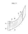
Fig. 3] Fig. 3 is a plan view of relevant portions of a turbine blade cascade endwall according to a third embodiment of the present invention. - [
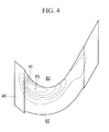
Fig. 4] Fig. 4 is a plan view of relevant portions of a turbine blade cascade endwall according to a fourth embodiment of the present invention. - [
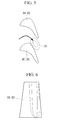
Fig. 5] Fig. 5 is a plan view of relevant portions of a turbine blade cascade endwall according to another embodiment of the present invention. - [
Fig. 6] Fig. 6 is a diagram showing isobaric lines at a suction side surface of a turbine stationary blade shown inFig. 5 . - A first embodiment of a turbine blade cascade endwall according to the present invention will be described below, with reference to
Fig. 1 .
As shown inFig. 1 , each turbine blade cascade endwall (hereinafter, referred to as "third-stage stationary-blade tip endwall) 10 according to this embodiment has afirst convex portion 11 between one turbine third-stage stationary blade (hereinafter, referred to as "third-stage stationary blade") B1 and another third-stage stationary blade B1 disposed adjacent to this third-stage stationary blade B1.
Note that, solid lines drawn on the third-stage stationary-blade tip endwall 10 inFig. 1 indicate contour lines of thefirst convex portion 11, contour lines of asecond convex portion 12, to be described later, and contour lines of athird convex portion 13, to be described later. - The
first convex portion 11 has an apex (peak) P1 at a position of 0 to 20 % pitch (substantially 7 % pitch in this embodiment) at a position of 5 to 25 % Cax (substantially 14 % Cax in this embodiment) and is, as a whole, a gently (smoothly) swollen portion which moderately slopes, from the apex P1, toward the downstream side and the suction side surface of the adjacently disposed third-stage stationary blade B1, and which slopes slightly steeply (slopes at a sloping angle that is larger (steeper) than a sloping angle toward the downstream side and the suction side surface of the adjacently disposed third-stage stationary blade B1 from the apex P1) toward the upstream side from the apex P1.
Here, 0 % Cax indicates a leading edge position of the third-stage stationary blade B1 in the axial direction, and 100 % Cax indicates a trailing edge position of the third-stage stationary blade B1 in the axial direction. - (minus) indicates a position on the upstream side going up from the leading edge position of the third-stage stationary blade B1 in the axial direction, and + (plus) indicates a position on the downstream side going down from the leading edge position of the third-stage stationary blade B1 in the axial direction. Furthermore, 0 % pitch indicates a position on the pressure side surface of the third-stage stationary blade B1, and 100 % pitch indicates a position on the suction side surface of the third-stage stationary blade B1.
The height (degree of convexity) of the apex P1 of thisfirst convex portion 11 is set at 5 % to 20 % (about 13 % in this embodiment) of the axial chord length of the third-stage stationary blade B1 (length of the third-stage stationary blade B1 in the axial direction). - Note that, as shown in
Fig. 1 , the third-stage stationary-blade tip endwall 10 according to this embodiment has, in addition to thefirst convex portion 11, asecond convex portion 12 that moderately slopes toward a base of thefirst convex portion 11 from a position of substantially 100 % pitch at a position of substantially 0 % Cax, and athird convex portion 13 that moderately slopes toward the base of thefirst convex portion 11 from a position of substantially 100 % pitch at a position of substantially 90 % Cax. - With the third-stage stationary-
blade tip endwall 10 according to this embodiment, because the static pressure near thefirst convex portion 11 can be reduced and the flow of working fluid in the axial direction can be increased, it is possible to reduce cross flow and to reduce secondary-flow loss that occurs in association with the crossflow; therefore, enhanced turbine performance can be achieved. - A second embodiment of a turbine blade cascade endwall according to the present invention will be described with reference to
Fig. 2 .
As shown inFig. 2 , each turbine blade cascade endwall (hereinafter, referred to as "third-stage stationary-blade hub endwall) 20 according to this embodiment has afourth convex portion 21 between one turbine third-stage stationary blade (hereinafter, referred to as "third-stage stationary blade") B1 and another third-stage stationary blade B1 disposed adjacent to this third-stage stationary blade B1. Note that, solid lines drawn on the third-stage stationary-blade hub endwall 20 inFig. 2 indicate contour lines of thefourth convex portion 21 and contour lines of afifth convex portion 22, to be described later. - The
fourth convex portion 21 has an apex (peak) P2 at a position of 0 to 20 % pitch (substantially 3 % pitch in this embodiment) at a position of 5 to 25 % Cax (substantially 14 % Cax in this embodiment) and is, as a whole, a gently (smoothly) swollen portion which moderately slopes from the apex P2 toward the downstream side and the suction side surface of the adjacently disposed third-stage stationary blade B1, and which slopes slightly steeply (slopes at a sloping angle that is larger (steeper) than a sloping angle toward the downstream side and the suction side surface of the adjacently disposed third-stage stationary blade B1 from the apex P2) toward the upstream side from the apex P2.
The height (degree of convexity) of the apex P2 of thisfourth convex portion 21 is set at 5 % to 20 % (about 12.5 % in this embodiment) of the axial chord length of the third-stage stationary blade B1 (length of the third-stage stationary blade B1 in the axial direction). - Note that, as shown in
Fig. 2 , the third-stage stationary-blade hub endwall 20 according to this embodiment has thefifth convex portion 22 that moderately slopes toward a base of thefourth convex portion 21 from a suction side surface located between substantially -10 % Cax and substantially 85 % Cax of the adjacently disposed third-stage stationary blade B1. - With the third-stage stationary-
blade hub endwall 20 according to this embodiment, because the static pressure near thefourth convex portion 21 can be reduced and the flow of working fluid in the axial direction can be increased, it is possible to reduce crossflow and to reduce secondary-flow loss that occurs in association with the crossflow; therefore, enhanced turbine performance can be achieved. - A third embodiment of a turbine blade cascade endwall according to the present invention will be described with reference to
Fig. 3 .
As shown inFig. 3 , each turbine blade cascade endwall (hereinafter, referred to as "fourth-stage stationary-blade tip endwall) 30 according to this embodiment has a firstconcave portion 31 between one turbine fourth-stage turbine stationary blade (hereinafter, referred to as "fourth-stage stationary blade") B2 and another fourth-stage stationary blade B2 disposed adjacent to this fourth-stage stationary blade B2. Note that, solid lines drawn on the fourth-stage stationary-blade tip endwall 30 inFig. 3 indicate isobathic lines of the firstconcave portion 31 and isobathic lines of asixth convex portion 32, to be described later. - The first
concave portion 31 has a bottom point (depression peak) P3 at a position of 70 to 90 % pitch (substantially 83 % pitch in this embodiment) at a position of 5 to 25 % Cax (substantially 17 % Cax in this embodiment) and is, as a whole, a gently (smoothly) depressed portion which moderately slopes from the bottom point P3 toward the downstream side and the pressure side surface of the adjacently disposed fourth-stage stationary blade B2, and which slopes slightly steeply (slopes at a sloping angle that is larger (steeper) than a sloping angle toward the downstream side and the pressure side surface of the adjacently disposed fourth-stage stationary blade B2 from the bottom point P3) toward the upstream side from the bottom point P3.
The depth (degree of concavity) of the bottom point P3 of this firstconcave portion 31 is set at 5 % to 15 % (about 6 % in this embodiment) of the axial chord length of the fourth-stage stationary blade B2 (length of the fourth-stage stationary blade B2 in the axial direction). - Note that, as shown in
Fig. 3 , the fourth-stage stationary-blade tip endwall 30 according to this embodiment has asixth convex portion 32 that has an apex (peak) P4 at a position of substantially 90 % pitch at a position of substantially 90 % Cax and that moderately slopes toward the bottom point P3 and a pressure side surface of the adjacently disposed fourth-stage stationary blade B2. - With the fourth-stage stationary-
blade tip endwall 30 according to this embodiment, because the static pressure near the firstconcave portion 31 can be increased and the flow of working fluid in the axial direction can be increased, it is possible to reduce crossflow and to reduce secondary-flow loss that occurs in association with the crossflow; therefore, enhanced turbine performance can be achieved. - A fourth embodiment of a turbine blade cascade endwall according to the present invention will be described with reference to
Fig. 4 .
As shown inFig. 4 , each turbine blade cascade endwall (hereinafter, referred to as "fourth-stage stationary-blade hub endwall) 40 according to this embodiment has a secondconcave portion 41 between one turbine fourth-stage stationary blade (hereinafter, referred to as "fourth-stage stationary blade") B2 and another fourth-stage stationary blade B2 disposed adjacent to this fourth-stage stationary blade B2. Note that, solid lines drawn on the fourth-stage stationary-blade hub endwall 40 inFig. 4 indicate isobathic lines of the secondconcave portion 41. - The second
concave portion 41 has a bottom point (depression peak) P5 at a position of 70 to 90 % pitch (substantially 81 % pitch in this embodiment) at a position of 5 to 25 % Cax (substantially 18 % Cax in this embodiment) and is, as a whole, a gently (smoothly) depressed portion which moderately slopes from the bottom point P5 toward the downstream side and the pressure side surface of the adjacently disposed fourth-stage stationary blade B2, and which slopes slightly steeply (slopes at a sloping angle that is larger (steeper) than a sloping angle toward the downstream side and the pressure side surface of the adjacently disposed fourth-stage stationary blade B2 from the bottom point P5) toward the upstream side from the bottom point P5.
The depth (degree of concavity) of the bottom point P5 of this secondconcave portion 41 is set at 5 % to 15 % (about 9.4 % in this embodiment) of the axial chord length of the fourth-stage stationary blade B2 (length of the fourth-stage stationary blade B2 in the axial direction). - With the fourth-stage stationary-
blade hub endwall 40 according to this embodiment, because the static pressure near the secondconcave portion 41 can be increased and the flow of working fluid in the axial direction can be increased, it is possible to reduce crossflow and to reduce secondary-flow loss that occurs in association with the crossflow; therefore, enhanced turbine performance can be achieved. - With a turbine equipped with the turbine
blade cascade endwall blade cascade endwall - As shown in
Fig. 5 , in the above-described embodiments, it is further preferable that a seventh convex portion 51 (not shown) be provided (formed) on the turbineblade cascade endwall
By providing such aseventh convex portion 51 on the turbineblade cascade endwall Fig. 6 ), as in the contour lines shown by the solid lines in the blade surface inFig. 6 , vortices generated at the suction side surfaces of the third-stage stationary blade B1 and the fourth-stage stationary blade B2 can be suppressed, and therefore, it is possible to reduce secondary-flow loss associated with these vortices. - The present invention is not limited to the above-described embodiments, and appropriate modifications, alterations, and combinations thereof that do not depart from the gist of the present invention are possible.
- In the above-described embodiments, a turbine blade cascade endwall has been described as exemplified in the third-stage stationary-blade tip endwall, the third-stage stationary-blade hub endwall, the fourth-stage stationary-blade tip endwall, and the fourth-stage stationary-blade hub endwall; however, the present invention is not limited thereto, and it can be applied to a hub endwall of turbine moving blades, a tip endwall of turbine moving blades, a stationary-blade tip endwall of other stages, or a stationary-blade tip endwall of other stages.
- Furthermore, the turbine blade cascade endwall according to the present invention can be applied to both a gas turbine and a steam turbine.
Claims (4)
- A turbine blade cascade endwall that is positioned on a tip side or a hub side of a plurality of turbine stationary blades or turbine moving blades arranged in the form of a ring, wherein,
defining 0% Cax as a leading edge position of the turbine stationary blades or the turbine moving blades in an axial direction and 100% Cax as a trailing edge position of the turbine stationary blades or the turbine moving blades in the axial direction, and defining 0% pitch as a position on a pressure side surface of the turbine stationary blades or the turbine moving blades and 100% pitch as a position on a suction side surface of a turbine stationary blade or a turbine moving blade facing the pressure side surface of the turbine stationary blade or the turbine moving blade,
a convex portion that is gently swollen as a whole, that has an apex at a position of 0 to 20 % pitch at a position of 5 to 25 % Cax, that gently slopes from this apex toward a downstream side and the suction side surface of the adjacently disposed turbine stationary blade or turbine moving blade, and that slopes slightly steeply from the apex toward an upstream side is provided between one turbine stationary blade or turbine moving blade and another turbine stationary blade or turbine moving blade disposed adjacent to one turbine stationary blade or turbine moving blade. - A turbine blade cascade endwall that is positioned on a tip side or a hub side of a plurality of turbine stationary blades or turbine moving blades arranged in the form of a ring, wherein,
defining 0% Cax as a leading edge position of the turbine stationary blades or the turbine moving blades in an axial direction and 100% Cax as a trailing edge position of the turbine stationary blades or the turbine moving blades in the axial direction, and defining 0% pitch as a position on a pressure side surface of the turbine stationary blades or the turbine moving blades and 100% pitch as a position on a suction side surface of a turbine stationary blade or a turbine moving blade facing the pressure side surface of the turbine stationary blade or the turbine moving blade,
a concave portion that is gently depressed as a whole, that has a bottom point at a position of 70 to 90 % pitch in a position of 5 to 25 % Cax, that gently slopes from this bottom point toward a downstream side and the pressure side surface of the adjacently disposed turbine stationary blade or turbine moving blade, and that slopes slightly steeply from the bottom point toward an upstream side is provided between one turbine stationary blade or turbine moving blade and another turbine stationary blade or turbine moving blade disposed adjacent to one turbine stationary blade or turbine moving blade. - A turbine blade cascade endwall according to Claim 1 or 2, wherein a second convex portion that is gently swollen as a whole or a convex portion is provided near a throat.
- A turbine provided with a turbine blade cascade endwall according to any one of Claims 1 to 3.
Applications Claiming Priority (2)
| Application Number | Priority Date | Filing Date | Title |
|---|---|---|---|
| JP2008030937A JP5291355B2 (en) | 2008-02-12 | 2008-02-12 | Turbine cascade endwall |
| PCT/JP2008/067231 WO2009101722A1 (en) | 2008-02-12 | 2008-09-25 | Turbine blade-cascade end wall |
Publications (3)
| Publication Number | Publication Date |
|---|---|
| EP2241723A1 true EP2241723A1 (en) | 2010-10-20 |
| EP2241723A4 EP2241723A4 (en) | 2013-03-06 |
| EP2241723B1 EP2241723B1 (en) | 2014-08-13 |
Family
ID=40956766
Family Applications (1)
| Application Number | Title | Priority Date | Filing Date |
|---|---|---|---|
| EP08872470.3A Active EP2241723B1 (en) | 2008-02-12 | 2008-09-25 | Turbine blade-cascade end wall |
Country Status (6)
| Country | Link |
|---|---|
| US (1) | US20100284818A1 (en) |
| EP (1) | EP2241723B1 (en) |
| JP (1) | JP5291355B2 (en) |
| KR (1) | KR20100097757A (en) |
| CN (1) | CN101925723B (en) |
| WO (1) | WO2009101722A1 (en) |
Cited By (2)
| Publication number | Priority date | Publication date | Assignee | Title |
|---|---|---|---|---|
| EP3404210A1 (en) * | 2017-05-15 | 2018-11-21 | MTU Aero Engines GmbH | Blade cascade segment for a turbomachine with non-axisymmetric platform surface, corresponding blade cascade, blade channel, platform, and turbomachine |
| EP3404211A1 (en) * | 2017-05-15 | 2018-11-21 | MTU Aero Engines GmbH | Blade cascade segment for a turbine with contoured platform surface, corresponding blade cascade, blade channel, platform, turbine and aircraft engine |
Families Citing this family (23)
| Publication number | Priority date | Publication date | Assignee | Title |
|---|---|---|---|---|
| US8403645B2 (en) | 2009-09-16 | 2013-03-26 | United Technologies Corporation | Turbofan flow path trenches |
| FR2950942B1 (en) * | 2009-10-02 | 2013-08-02 | Snecma | ROTOR OF A TURBOMACHINE COMPRESSOR WITH OPTIMIZED INTERNAL END WALL |
| JP2012233406A (en) * | 2011-04-28 | 2012-11-29 | Hitachi Ltd | Gas turbine stator vane |
| JP5842382B2 (en) | 2011-05-13 | 2016-01-13 | 株式会社Ihi | Gas turbine engine |
| US8915706B2 (en) | 2011-10-18 | 2014-12-23 | General Electric Company | Transition nozzle |
| US9051843B2 (en) | 2011-10-28 | 2015-06-09 | General Electric Company | Turbomachine blade including a squeeler pocket |
| US8992179B2 (en) * | 2011-10-28 | 2015-03-31 | General Electric Company | Turbine of a turbomachine |
| US8967959B2 (en) | 2011-10-28 | 2015-03-03 | General Electric Company | Turbine of a turbomachine |
| US9255480B2 (en) | 2011-10-28 | 2016-02-09 | General Electric Company | Turbine of a turbomachine |
| CN102536329B (en) * | 2011-12-31 | 2014-04-02 | 西北工业大学 | Modeling method for axis-asymmetric end wall of annular blade grid of air compressor or turbine |
| US9103213B2 (en) | 2012-02-29 | 2015-08-11 | General Electric Company | Scalloped surface turbine stage with purge trough |
| US9085985B2 (en) | 2012-03-23 | 2015-07-21 | General Electric Company | Scalloped surface turbine stage |
| US9267386B2 (en) | 2012-06-29 | 2016-02-23 | United Technologies Corporation | Fairing assembly |
| EP2696029B1 (en) * | 2012-08-09 | 2015-10-07 | MTU Aero Engines AG | Blade row with side wall contours and fluid flow engine |
| EP2885506B8 (en) | 2012-08-17 | 2021-03-31 | Raytheon Technologies Corporation | Contoured flowpath surface |
| CN106089806A (en) * | 2016-05-30 | 2016-11-09 | 西北工业大学 | A kind of diffuser that reduces separates the end wall processing method of loss |
| DE102016211315A1 (en) | 2016-06-23 | 2017-12-28 | MTU Aero Engines AG | Runner or vane with raised areas |
| EP3369892B1 (en) * | 2017-03-03 | 2020-08-19 | MTU Aero Engines GmbH | Contouring of a blade row platform |
| CN111919013B (en) * | 2018-03-30 | 2022-11-15 | 西门子能源全球两合公司 | Turbine stage platform with end wall contouring incorporating wave-shaped mating surfaces |
| US11415012B1 (en) * | 2021-09-03 | 2022-08-16 | Pratt & Whitney Canada Corp. | Tandem stator with depressions in gaspath wall |
| US11639666B2 (en) | 2021-09-03 | 2023-05-02 | Pratt & Whitney Canada Corp. | Stator with depressions in gaspath wall adjacent leading edges |
| CN114542502B (en) * | 2022-01-26 | 2023-05-26 | 西北工业大学 | Adjustable compressor/turbine blade cascade experimental device of blade cascade front end wall vortex generator |
| DE102022113750A1 (en) | 2022-05-31 | 2023-11-30 | MTU Aero Engines AG | Annulus contouring |
Family Cites Families (16)
| Publication number | Priority date | Publication date | Assignee | Title |
|---|---|---|---|---|
| GB944166A (en) * | 1960-03-02 | 1963-12-11 | Werner Hausammann | Rotor for turbines or compressors |
| GB9417406D0 (en) * | 1994-08-30 | 1994-10-19 | Gec Alsthom Ltd | Turbine blade |
| DE19650656C1 (en) * | 1996-12-06 | 1998-06-10 | Mtu Muenchen Gmbh | Turbo machine with transonic compressor stage |
| CN2288271Y (en) * | 1997-05-13 | 1998-08-19 | 北京全三维动力工程有限公司 | Cambered stator blade grid for tangential turbine |
| GB9823840D0 (en) * | 1998-10-30 | 1998-12-23 | Rolls Royce Plc | Bladed ducting for turbomachinery |
| US6419446B1 (en) * | 1999-08-05 | 2002-07-16 | United Technologies Corporation | Apparatus and method for inhibiting radial transfer of core gas flow within a core gas flow path of a gas turbine engine |
| US6669445B2 (en) * | 2002-03-07 | 2003-12-30 | United Technologies Corporation | Endwall shape for use in turbomachinery |
| US6969232B2 (en) * | 2002-10-23 | 2005-11-29 | United Technologies Corporation | Flow directing device |
| JP4346412B2 (en) * | 2003-10-31 | 2009-10-21 | 株式会社東芝 | Turbine cascade |
| WO2006033407A1 (en) * | 2004-09-24 | 2006-03-30 | Ishikawajima-Harima Heavy Industries Co., Ltd. | Wall shape of axial flow machine and gas turbine engine |
| EP1828543B1 (en) * | 2004-12-21 | 2016-03-16 | Honeywell International Inc. | Turbine wheel with backswept inducer |
| US7134842B2 (en) * | 2004-12-24 | 2006-11-14 | General Electric Company | Scalloped surface turbine stage |
| US7220100B2 (en) * | 2005-04-14 | 2007-05-22 | General Electric Company | Crescentic ramp turbine stage |
| GB0518628D0 (en) * | 2005-09-13 | 2005-10-19 | Rolls Royce Plc | Axial compressor blading |
| JP4616781B2 (en) * | 2006-03-16 | 2011-01-19 | 三菱重工業株式会社 | Turbine cascade endwall |
| US7887297B2 (en) * | 2006-05-02 | 2011-02-15 | United Technologies Corporation | Airfoil array with an endwall protrusion and components of the array |
-
2008
- 2008-02-12 JP JP2008030937A patent/JP5291355B2/en active Active
- 2008-09-25 US US12/812,115 patent/US20100284818A1/en not_active Abandoned
- 2008-09-25 CN CN200880125635.7A patent/CN101925723B/en active Active
- 2008-09-25 EP EP08872470.3A patent/EP2241723B1/en active Active
- 2008-09-25 KR KR1020107016954A patent/KR20100097757A/en not_active Ceased
- 2008-09-25 WO PCT/JP2008/067231 patent/WO2009101722A1/en not_active Ceased
Cited By (3)
| Publication number | Priority date | Publication date | Assignee | Title |
|---|---|---|---|---|
| EP3404210A1 (en) * | 2017-05-15 | 2018-11-21 | MTU Aero Engines GmbH | Blade cascade segment for a turbomachine with non-axisymmetric platform surface, corresponding blade cascade, blade channel, platform, and turbomachine |
| EP3404211A1 (en) * | 2017-05-15 | 2018-11-21 | MTU Aero Engines GmbH | Blade cascade segment for a turbine with contoured platform surface, corresponding blade cascade, blade channel, platform, turbine and aircraft engine |
| US10934849B2 (en) | 2017-05-15 | 2021-03-02 | MTU Aero Engines AG | Endwall contouring for a turbomachine |
Also Published As
| Publication number | Publication date |
|---|---|
| KR20100097757A (en) | 2010-09-03 |
| CN101925723B (en) | 2016-06-01 |
| CN101925723A (en) | 2010-12-22 |
| EP2241723B1 (en) | 2014-08-13 |
| WO2009101722A1 (en) | 2009-08-20 |
| JP2009191656A (en) | 2009-08-27 |
| EP2241723A4 (en) | 2013-03-06 |
| JP5291355B2 (en) | 2013-09-18 |
| US20100284818A1 (en) | 2010-11-11 |
| CN104165070A (en) | 2014-11-26 |
Similar Documents
| Publication | Publication Date | Title |
|---|---|---|
| EP2241723B1 (en) | Turbine blade-cascade end wall | |
| EP2187000B1 (en) | Turbine blade-cascade end wall | |
| CN101371007B (en) | Turbine cascade end wall | |
| CN104005991B (en) | Impeller | |
| JP5554542B2 (en) | System and method for reducing bucket tip loss | |
| CN102483072B (en) | Compressor rotor blades for axial compressors | |
| CN101775999B (en) | Methods and apparatus relating to improved turbine blade platform contours | |
| EP2476862B1 (en) | Vane for an axial flow turbomachine and corresponding turbomachine | |
| US9453415B2 (en) | Blade cascade with side wall contours and continuous-flow machine | |
| EP2441964A3 (en) | Axial compressor | |
| US20180298912A1 (en) | Compressor blades and/or vanes | |
| US9863251B2 (en) | Turbomachine and turbomachine stage | |
| US8777564B2 (en) | Hybrid flow blade design | |
| US20170204878A1 (en) | Controlled convergence compressor flowpath for a gas turbine engine | |
| CN106574508A (en) | The fluted top of a turbine turbine blade | |
| US9896940B2 (en) | Blade for a gas turbomachine | |
| EP2586973B1 (en) | Blade for a gas turbine engine | |
| JP5490178B2 (en) | Turbine cascade endwall | |
| JP5721760B2 (en) | Turbine cascade endwall | |
| US8137062B2 (en) | Turbomachine nozzle |
Legal Events
| Date | Code | Title | Description |
|---|---|---|---|
| PUAI | Public reference made under article 153(3) epc to a published international application that has entered the european phase |
Free format text: ORIGINAL CODE: 0009012 |
|
| 17P | Request for examination filed |
Effective date: 20100713 |
|
| AK | Designated contracting states |
Kind code of ref document: A1 Designated state(s): AT BE BG CH CY CZ DE DK EE ES FI FR GB GR HR HU IE IS IT LI LT LU LV MC MT NL NO PL PT RO SE SI SK TR |
|
| AX | Request for extension of the european patent |
Extension state: AL BA MK RS |
|
| DAX | Request for extension of the european patent (deleted) | ||
| A4 | Supplementary search report drawn up and despatched |
Effective date: 20130201 |
|
| RIC1 | Information provided on ipc code assigned before grant |
Ipc: F01D 9/04 20060101ALI20130128BHEP Ipc: F01D 5/14 20060101ALI20130128BHEP Ipc: F01D 9/02 20060101AFI20130128BHEP |
|
| GRAP | Despatch of communication of intention to grant a patent |
Free format text: ORIGINAL CODE: EPIDOSNIGR1 |
|
| INTG | Intention to grant announced |
Effective date: 20131029 |
|
| RIN1 | Information on inventor provided before grant (corrected) |
Inventor name: WAKAZONO, SUSUMU Inventor name: SAKAMOTO, YASURO Inventor name: ITO, EISAKU Inventor name: HIYAMA, TAKASHI |
|
| GRAS | Grant fee paid |
Free format text: ORIGINAL CODE: EPIDOSNIGR3 |
|
| GRAA | (expected) grant |
Free format text: ORIGINAL CODE: 0009210 |
|
| RAP1 | Party data changed (applicant data changed or rights of an application transferred) |
Owner name: MITSUBISHI HITACHI POWER SYSTEMS, LTD. |
|
| AK | Designated contracting states |
Kind code of ref document: B1 Designated state(s): AT BE BG CH CY CZ DE DK EE ES FI FR GB GR HR HU IE IS IT LI LT LU LV MC MT NL NO PL PT RO SE SI SK TR |
|
| REG | Reference to a national code |
Ref country code: GB Ref legal event code: FG4D |
|
| REG | Reference to a national code |
Ref country code: AT Ref legal event code: REF Ref document number: 682397 Country of ref document: AT Kind code of ref document: T Effective date: 20140815 Ref country code: CH Ref legal event code: EP |
|
| REG | Reference to a national code |
Ref country code: IE Ref legal event code: FG4D |
|
| REG | Reference to a national code |
Ref country code: DE Ref legal event code: R096 Ref document number: 602008033895 Country of ref document: DE Effective date: 20140925 |
|
| REG | Reference to a national code |
Ref country code: NL Ref legal event code: VDEP Effective date: 20140813 |
|
| REG | Reference to a national code |
Ref country code: AT Ref legal event code: MK05 Ref document number: 682397 Country of ref document: AT Kind code of ref document: T Effective date: 20140813 |
|
| REG | Reference to a national code |
Ref country code: LT Ref legal event code: MG4D |
|
| PG25 | Lapsed in a contracting state [announced via postgrant information from national office to epo] |
Ref country code: ES Free format text: LAPSE BECAUSE OF FAILURE TO SUBMIT A TRANSLATION OF THE DESCRIPTION OR TO PAY THE FEE WITHIN THE PRESCRIBED TIME-LIMIT Effective date: 20140813 Ref country code: LT Free format text: LAPSE BECAUSE OF FAILURE TO SUBMIT A TRANSLATION OF THE DESCRIPTION OR TO PAY THE FEE WITHIN THE PRESCRIBED TIME-LIMIT Effective date: 20140813 Ref country code: NO Free format text: LAPSE BECAUSE OF FAILURE TO SUBMIT A TRANSLATION OF THE DESCRIPTION OR TO PAY THE FEE WITHIN THE PRESCRIBED TIME-LIMIT Effective date: 20141113 Ref country code: PT Free format text: LAPSE BECAUSE OF FAILURE TO SUBMIT A TRANSLATION OF THE DESCRIPTION OR TO PAY THE FEE WITHIN THE PRESCRIBED TIME-LIMIT Effective date: 20141215 Ref country code: SE Free format text: LAPSE BECAUSE OF FAILURE TO SUBMIT A TRANSLATION OF THE DESCRIPTION OR TO PAY THE FEE WITHIN THE PRESCRIBED TIME-LIMIT Effective date: 20140813 Ref country code: BG Free format text: LAPSE BECAUSE OF FAILURE TO SUBMIT A TRANSLATION OF THE DESCRIPTION OR TO PAY THE FEE WITHIN THE PRESCRIBED TIME-LIMIT Effective date: 20141113 Ref country code: FI Free format text: LAPSE BECAUSE OF FAILURE TO SUBMIT A TRANSLATION OF THE DESCRIPTION OR TO PAY THE FEE WITHIN THE PRESCRIBED TIME-LIMIT Effective date: 20140813 Ref country code: GR Free format text: LAPSE BECAUSE OF FAILURE TO SUBMIT A TRANSLATION OF THE DESCRIPTION OR TO PAY THE FEE WITHIN THE PRESCRIBED TIME-LIMIT Effective date: 20141114 |
|
| PG25 | Lapsed in a contracting state [announced via postgrant information from national office to epo] |
Ref country code: IS Free format text: LAPSE BECAUSE OF FAILURE TO SUBMIT A TRANSLATION OF THE DESCRIPTION OR TO PAY THE FEE WITHIN THE PRESCRIBED TIME-LIMIT Effective date: 20141213 Ref country code: CY Free format text: LAPSE BECAUSE OF FAILURE TO SUBMIT A TRANSLATION OF THE DESCRIPTION OR TO PAY THE FEE WITHIN THE PRESCRIBED TIME-LIMIT Effective date: 20140813 Ref country code: LV Free format text: LAPSE BECAUSE OF FAILURE TO SUBMIT A TRANSLATION OF THE DESCRIPTION OR TO PAY THE FEE WITHIN THE PRESCRIBED TIME-LIMIT Effective date: 20140813 Ref country code: AT Free format text: LAPSE BECAUSE OF FAILURE TO SUBMIT A TRANSLATION OF THE DESCRIPTION OR TO PAY THE FEE WITHIN THE PRESCRIBED TIME-LIMIT Effective date: 20140813 Ref country code: HR Free format text: LAPSE BECAUSE OF FAILURE TO SUBMIT A TRANSLATION OF THE DESCRIPTION OR TO PAY THE FEE WITHIN THE PRESCRIBED TIME-LIMIT Effective date: 20140813 |
|
| PG25 | Lapsed in a contracting state [announced via postgrant information from national office to epo] |
Ref country code: NL Free format text: LAPSE BECAUSE OF FAILURE TO SUBMIT A TRANSLATION OF THE DESCRIPTION OR TO PAY THE FEE WITHIN THE PRESCRIBED TIME-LIMIT Effective date: 20140813 |
|
| RAP2 | Party data changed (patent owner data changed or rights of a patent transferred) |
Owner name: MITSUBISHI HITACHI POWER SYSTEMS, LTD. |
|
| PG25 | Lapsed in a contracting state [announced via postgrant information from national office to epo] |
Ref country code: SK Free format text: LAPSE BECAUSE OF FAILURE TO SUBMIT A TRANSLATION OF THE DESCRIPTION OR TO PAY THE FEE WITHIN THE PRESCRIBED TIME-LIMIT Effective date: 20140813 Ref country code: DK Free format text: LAPSE BECAUSE OF FAILURE TO SUBMIT A TRANSLATION OF THE DESCRIPTION OR TO PAY THE FEE WITHIN THE PRESCRIBED TIME-LIMIT Effective date: 20140813 Ref country code: RO Free format text: LAPSE BECAUSE OF FAILURE TO SUBMIT A TRANSLATION OF THE DESCRIPTION OR TO PAY THE FEE WITHIN THE PRESCRIBED TIME-LIMIT Effective date: 20140813 Ref country code: EE Free format text: LAPSE BECAUSE OF FAILURE TO SUBMIT A TRANSLATION OF THE DESCRIPTION OR TO PAY THE FEE WITHIN THE PRESCRIBED TIME-LIMIT Effective date: 20140813 Ref country code: CZ Free format text: LAPSE BECAUSE OF FAILURE TO SUBMIT A TRANSLATION OF THE DESCRIPTION OR TO PAY THE FEE WITHIN THE PRESCRIBED TIME-LIMIT Effective date: 20140813 Ref country code: IT Free format text: LAPSE BECAUSE OF FAILURE TO SUBMIT A TRANSLATION OF THE DESCRIPTION OR TO PAY THE FEE WITHIN THE PRESCRIBED TIME-LIMIT Effective date: 20140813 |
|
| REG | Reference to a national code |
Ref country code: CH Ref legal event code: PL |
|
| REG | Reference to a national code |
Ref country code: DE Ref legal event code: R097 Ref document number: 602008033895 Country of ref document: DE |
|
| PG25 | Lapsed in a contracting state [announced via postgrant information from national office to epo] |
Ref country code: PL Free format text: LAPSE BECAUSE OF FAILURE TO SUBMIT A TRANSLATION OF THE DESCRIPTION OR TO PAY THE FEE WITHIN THE PRESCRIBED TIME-LIMIT Effective date: 20140813 Ref country code: MC Free format text: LAPSE BECAUSE OF FAILURE TO SUBMIT A TRANSLATION OF THE DESCRIPTION OR TO PAY THE FEE WITHIN THE PRESCRIBED TIME-LIMIT Effective date: 20140813 |
|
| REG | Reference to a national code |
Ref country code: IE Ref legal event code: MM4A |
|
| PLBE | No opposition filed within time limit |
Free format text: ORIGINAL CODE: 0009261 |
|
| STAA | Information on the status of an ep patent application or granted ep patent |
Free format text: STATUS: NO OPPOSITION FILED WITHIN TIME LIMIT |
|
| REG | Reference to a national code |
Ref country code: FR Ref legal event code: ST Effective date: 20150529 |
|
| PG25 | Lapsed in a contracting state [announced via postgrant information from national office to epo] |
Ref country code: BE Free format text: LAPSE BECAUSE OF NON-PAYMENT OF DUE FEES Effective date: 20140930 |
|
| 26N | No opposition filed |
Effective date: 20150515 |
|
| GBPC | Gb: european patent ceased through non-payment of renewal fee |
Effective date: 20141113 |
|
| PG25 | Lapsed in a contracting state [announced via postgrant information from national office to epo] |
Ref country code: LI Free format text: LAPSE BECAUSE OF NON-PAYMENT OF DUE FEES Effective date: 20140930 Ref country code: CH Free format text: LAPSE BECAUSE OF NON-PAYMENT OF DUE FEES Effective date: 20140930 |
|
| PG25 | Lapsed in a contracting state [announced via postgrant information from national office to epo] |
Ref country code: IE Free format text: LAPSE BECAUSE OF NON-PAYMENT OF DUE FEES Effective date: 20140925 Ref country code: FR Free format text: LAPSE BECAUSE OF NON-PAYMENT OF DUE FEES Effective date: 20141013 |
|
| PG25 | Lapsed in a contracting state [announced via postgrant information from national office to epo] |
Ref country code: GB Free format text: LAPSE BECAUSE OF NON-PAYMENT OF DUE FEES Effective date: 20141113 |
|
| PG25 | Lapsed in a contracting state [announced via postgrant information from national office to epo] |
Ref country code: SI Free format text: LAPSE BECAUSE OF FAILURE TO SUBMIT A TRANSLATION OF THE DESCRIPTION OR TO PAY THE FEE WITHIN THE PRESCRIBED TIME-LIMIT Effective date: 20140813 |
|
| PG25 | Lapsed in a contracting state [announced via postgrant information from national office to epo] |
Ref country code: MT Free format text: LAPSE BECAUSE OF FAILURE TO SUBMIT A TRANSLATION OF THE DESCRIPTION OR TO PAY THE FEE WITHIN THE PRESCRIBED TIME-LIMIT Effective date: 20140813 |
|
| PG25 | Lapsed in a contracting state [announced via postgrant information from national office to epo] |
Ref country code: TR Free format text: LAPSE BECAUSE OF FAILURE TO SUBMIT A TRANSLATION OF THE DESCRIPTION OR TO PAY THE FEE WITHIN THE PRESCRIBED TIME-LIMIT Effective date: 20140813 Ref country code: LU Free format text: LAPSE BECAUSE OF NON-PAYMENT OF DUE FEES Effective date: 20140925 Ref country code: HU Free format text: LAPSE BECAUSE OF FAILURE TO SUBMIT A TRANSLATION OF THE DESCRIPTION OR TO PAY THE FEE WITHIN THE PRESCRIBED TIME-LIMIT; INVALID AB INITIO Effective date: 20080925 Ref country code: BE Free format text: LAPSE BECAUSE OF FAILURE TO SUBMIT A TRANSLATION OF THE DESCRIPTION OR TO PAY THE FEE WITHIN THE PRESCRIBED TIME-LIMIT Effective date: 20140813 |
|
| REG | Reference to a national code |
Ref country code: DE Ref legal event code: R082 Ref document number: 602008033895 Country of ref document: DE Representative=s name: HENKEL & PARTNER MBB PATENTANWALTSKANZLEI, REC, DE Ref country code: DE Ref legal event code: R081 Ref document number: 602008033895 Country of ref document: DE Owner name: MITSUBISHI POWER, LTD., JP Free format text: FORMER OWNER: MITSUBISHI HITACHI POWER SYSTEMS, LTD., YOKOHAMA-SHI, KANAGAWA, JP |
|
| PGFP | Annual fee paid to national office [announced via postgrant information from national office to epo] |
Ref country code: DE Payment date: 20250730 Year of fee payment: 18 |