EP2241721A2 - Airfoil with feature against flow separation, corresponding gas turbine engine and operating method - Google Patents
Airfoil with feature against flow separation, corresponding gas turbine engine and operating method Download PDFInfo
- Publication number
- EP2241721A2 EP2241721A2 EP10250340A EP10250340A EP2241721A2 EP 2241721 A2 EP2241721 A2 EP 2241721A2 EP 10250340 A EP10250340 A EP 10250340A EP 10250340 A EP10250340 A EP 10250340A EP 2241721 A2 EP2241721 A2 EP 2241721A2
- Authority
- EP
- European Patent Office
- Prior art keywords
- airfoil
- airfoils
- assembly
- gas turbine
- leading edge
- Prior art date
- Legal status (The legal status is an assumption and is not a legal conclusion. Google has not performed a legal analysis and makes no representation as to the accuracy of the status listed.)
- Granted
Links
Images

Classifications
-
- F—MECHANICAL ENGINEERING; LIGHTING; HEATING; WEAPONS; BLASTING
- F01—MACHINES OR ENGINES IN GENERAL; ENGINE PLANTS IN GENERAL; STEAM ENGINES
- F01D—NON-POSITIVE DISPLACEMENT MACHINES OR ENGINES, e.g. STEAM TURBINES
- F01D5/00—Blades; Blade-carrying members; Heating, heat-insulating, cooling or antivibration means on the blades or the members
- F01D5/12—Blades
- F01D5/14—Form or construction
- F01D5/141—Shape, i.e. outer, aerodynamic form
- F01D5/142—Shape, i.e. outer, aerodynamic form of the blades of successive rotor or stator blade-rows
- F01D5/143—Contour of the outer or inner working fluid flow path wall, i.e. shroud or hub contour
-
- F—MECHANICAL ENGINEERING; LIGHTING; HEATING; WEAPONS; BLASTING
- F05—INDEXING SCHEMES RELATING TO ENGINES OR PUMPS IN VARIOUS SUBCLASSES OF CLASSES F01-F04
- F05D—INDEXING SCHEME FOR ASPECTS RELATING TO NON-POSITIVE-DISPLACEMENT MACHINES OR ENGINES, GAS-TURBINES OR JET-PROPULSION PLANTS
- F05D2240/00—Components
- F05D2240/10—Stators
- F05D2240/12—Fluid guiding means, e.g. vanes
- F05D2240/121—Fluid guiding means, e.g. vanes related to the leading edge of a stator vane
-
- F—MECHANICAL ENGINEERING; LIGHTING; HEATING; WEAPONS; BLASTING
- F05—INDEXING SCHEMES RELATING TO ENGINES OR PUMPS IN VARIOUS SUBCLASSES OF CLASSES F01-F04
- F05D—INDEXING SCHEME FOR ASPECTS RELATING TO NON-POSITIVE-DISPLACEMENT MACHINES OR ENGINES, GAS-TURBINES OR JET-PROPULSION PLANTS
- F05D2240/00—Components
- F05D2240/20—Rotors
- F05D2240/30—Characteristics of rotor blades, i.e. of any element transforming dynamic fluid energy to or from rotational energy and being attached to a rotor
- F05D2240/303—Characteristics of rotor blades, i.e. of any element transforming dynamic fluid energy to or from rotational energy and being attached to a rotor related to the leading edge of a rotor blade
-
- F—MECHANICAL ENGINEERING; LIGHTING; HEATING; WEAPONS; BLASTING
- F05—INDEXING SCHEMES RELATING TO ENGINES OR PUMPS IN VARIOUS SUBCLASSES OF CLASSES F01-F04
- F05D—INDEXING SCHEME FOR ASPECTS RELATING TO NON-POSITIVE-DISPLACEMENT MACHINES OR ENGINES, GAS-TURBINES OR JET-PROPULSION PLANTS
- F05D2250/00—Geometry
- F05D2250/70—Shape
- F05D2250/71—Shape curved
- F05D2250/711—Shape curved convex
Definitions
- This application relates generally to gas turbine engine airfoil arrays. More particularly, this application relates to influencing fluid flow near the leading edge portions of the airfoils within the airfoil array.
- Gas turbine engines are known and typically include multiple sections, such as a fan section, a compression section, a combustor section, a turbine section, and an exhaust nozzle section.
- the fan section moves air into the engine.
- the air is compressed in the compression section.
- the compressed air is mixed with fuel and is combusted in the combustor section. Products of the combustion expand to rotatably drive the engine.
- Some sections of the engine include vane arrays, blade arrays, or both. Air within the engine moves through fluid flow passages in the arrays.
- the fluid flow passages are established by adjacent airfoils projecting from laterally extending endwalls.
- air approaching the fluid flow passages can separate from portions of the arrays.
- the separation within the engine can disadvantageously increase aerodynamic losses and can contribute to locally increased convective heat loads.
- the separation often occurs in vane arrays or blade arrays having airfoils with low camber angles, such as some of the airfoils within the turbine section of the engine.
- An example airfoil assembly includes a base having an airfoil projecting radially therefrom.
- the base extends laterally away from the airfoil.
- the airfoil extends axially from an airfoil leading edge portion to an airfoil trailing edge portion.
- the base has a humped area forward the airfoil leading edge portion.
- An example gas turbine engine assembly includes an endwall and an array of airfoils circumferentially distributed about an axis.
- the endwall and the airfoils establish a plurality of fluid flow passages.
- a plurality of convex features is circumferentially distributed about the axis. At least a portion of the convex features are positioned axially forward the fluid flow passages and is configured to influence flow through the fluid flow passages.
- An example method of influencing flow within a gas turbine engine includes moving a fluid axially toward a fluid flow passage established between adjacent airfoils in a gas turbine engine.
- the airfoils project radially from an endwall.
- the method also includes limiting flow separation of the fluid near at least one of the airfoils using a hump projecting from the endwall.
- Figure 1 schematically illustrates an example gas turbine engine 10 including (in serial flow communication) a fan section 14, a low-pressure compressor 18, a high-pressure compressor 22, a combustor 26, a high-pressure turbine 30, and a low-pressure turbine 34.
- the gas turbine engine 10 is circumferentially disposed about an engine centerline X.
- air is pulled into the gas turbine engine 10 by the fan section 14, pressurized by the compressors 18 and 22, mixed with fuel, and burned in the combustor 26.
- the turbines 30 and 34 extract energy from the hot combustion gases flowing from the combustor 26.
- the high-pressure turbine 30 utilizes the extracted energy from the hot combustion gases to power the high-pressure compressor 22 through a high speed shaft 38.
- the low-pressure turbine 34 utilizes the extracted energy from the hot combustion gases to power the low-pressure compressor 18 and the fan section 14 through a low speed shaft 42.
- the examples described in this disclosure are not limited to the two-spool architecture described and may be used in other architectures, such as a single-spool axial design, a three-spool axial design, and still other architectures. That is, there are various types of engines that could benefit from the examples disclosed herein, which are not limited to the design shown.
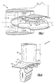
- an example airfoil array 50 includes a plurality of airfoils 54 circumferentially arranged about the engine centerline X.
- the airfoils 54 project radially from an endwall 58 comprised of a plurality of airfoil bases 60.
- the airfoil array 50 is mounted for rotation within the engine 10 about the engine centerline X.
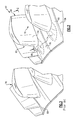
- an airfoil assembly 61 includes one of the airfoils 54 and one of the bases 60.
- the airfoils span between two bases and are not mounted for rotation within the engine 10.
- the airfoils 54 extend axially from an airfoil leading edge portion 62 to an airfoil trailing edge portion 66. Adjacent ones of the airfoils 54 establish a flow passage 70 with the endwall 58. As known, fluid flow, such as airflow, moves toward the flow passage 70 from a position forward the leading edge portion 62 of the airfoils 54 as the engine 10 operates.
- the endwall 58 includes a hump 74 extending axially forward the leading edge portions 62 of the airfoils 54 within the airfoil array 50.
- the example hump 74 extends radially away from the engine centerline X relative to a surface 76 of the endwall 58 adjacent the hump 74.
- the example airfoils 54 project radially outward from the endwall 58 having the hump 74.
- the airfoils 54 project radially inward from an endwall having the hump 74, and the hump 74 extends radially inward toward the engine centerline X.
- An endwall 80 in a prior art airfoil array 78 ( Figure 3 ) lacks the hump 74.
- a surface 72 of the hump 74 is convex (forming a convex feature) in this example relative to a surface 76 of the endwall adjacent the hump 74. That is, the concavity of the surface 72 of the hump 74 projects radially inward. At least a portion of the example hump 74 is axially forward the leading edge portion 62 of the airfoil 54, which enables the hump 74 to influence flow prior to the flow entering the flow passage 70.
- the example hump 74 has a radial peak 82 at an interface 86 of the hump 74 and the airfoil 54.
- the radial peak 82 of the hump 74 is axially forward the interface 86.
- some portions of the hump 74 extend rearward into the flow passage 70, the radial peak 82 of the hump 74 is forward the leading edge portion 62 and thus forward the flow passage 70.
- the radial peak 82 of the hump 74 is axially rearward the interface 86.
- a radial height h1 of the hump 74 corresponds to the distance between the surface 76 of the endwall 58 and the radial peak 82.
- the radial height h1 of the hump 74 is between 5% and 25% the radial height h2, or span, of the airfoil 54.
- the example airfoil 54 is a low camber airfoil, which typically corresponds to airfoil 54 having a camber angle ⁇ of less than 60°. In this example, the camber angle ⁇ of the airfoil 54 is about 30°. As known, low camber airfoils, such as the airfoil 54, are particularly prone to separation of flow near the leading edge portions 62. Higher camber airfoils, however, could also benefit from the hump 74.
- the example airfoil array 50 the airfoil array 50 is a turbine exit guide vane assembly.
- the airfoil array 50 is a mid-turbine frame component that is positioned axially between the high-pressure turbine 30 and the low-pressure turbine 34 of the engine 10 ( Figure 1 ).
- mid-turbine frame components may include airfoils having 0 camber angle.
- the airfoil array 50 is a counter rotating vane assembly.
- Features of the disclosed embodiments include reducing convective heat loads and improving aerodynamic performance of airfoil arrays by positioning a hump near the leading edges of airfoils within the airfoil array, and particularly the leading edges of low camber airfoils.
- the hump is configured to influence the flow through the flow passages defined between the airfoils and in particular to limit separation of the flow adjacent the flow passages.
Abstract
Description
- This application relates generally to gas turbine engine airfoil arrays. More particularly, this application relates to influencing fluid flow near the leading edge portions of the airfoils within the airfoil array.
- Gas turbine engines are known and typically include multiple sections, such as a fan section, a compression section, a combustor section, a turbine section, and an exhaust nozzle section. The fan section moves air into the engine. The air is compressed in the compression section. The compressed air is mixed with fuel and is combusted in the combustor section. Products of the combustion expand to rotatably drive the engine.
- Some sections of the engine include vane arrays, blade arrays, or both. Air within the engine moves through fluid flow passages in the arrays. The fluid flow passages are established by adjacent airfoils projecting from laterally extending endwalls. As known, air approaching the fluid flow passages can separate from portions of the arrays. The separation within the engine can disadvantageously increase aerodynamic losses and can contribute to locally increased convective heat loads. The separation often occurs in vane arrays or blade arrays having airfoils with low camber angles, such as some of the airfoils within the turbine section of the engine.
- An example airfoil assembly includes a base having an airfoil projecting radially therefrom. The base extends laterally away from the airfoil. The airfoil extends axially from an airfoil leading edge portion to an airfoil trailing edge portion. The base has a humped area forward the airfoil leading edge portion.
- An example gas turbine engine assembly includes an endwall and an array of airfoils circumferentially distributed about an axis. The endwall and the airfoils establish a plurality of fluid flow passages. A plurality of convex features is circumferentially distributed about the axis. At least a portion of the convex features are positioned axially forward the fluid flow passages and is configured to influence flow through the fluid flow passages.
- An example method of influencing flow within a gas turbine engine includes moving a fluid axially toward a fluid flow passage established between adjacent airfoils in a gas turbine engine. The airfoils project radially from an endwall. The method also includes limiting flow separation of the fluid near at least one of the airfoils using a hump projecting from the endwall.
- These and other features of the example disclosure can be best understood from the following specification and drawings, the following of which is a brief description:
-
-
Figure 1 shows a schematic view of an example gas turbine engine. -
Figure 2 shows a perspective view of an example airfoil array within theFigure 1 engine. -
Figure 3 shows a prior art airfoil array. -
Figure 4 shows a perspective view of an example airfoil assembly from theFigure 2 airfoil array. -
Figure 5 shows a sectional view taken at line 5-5 ofFigure 2 . -
Figure 6 shows a sectional view taken at line 6-6 ofFigure 5 . -
Figure 1 schematically illustrates an examplegas turbine engine 10 including (in serial flow communication) afan section 14, a low-pressure compressor 18, a high-pressure compressor 22, acombustor 26, a high-pressure turbine 30, and a low-pressure turbine 34. Thegas turbine engine 10 is circumferentially disposed about an engine centerline X. During operation, air is pulled into thegas turbine engine 10 by thefan section 14, pressurized by thecompressors combustor 26. Theturbines combustor 26. - In a two-spool design, the high-
pressure turbine 30 utilizes the extracted energy from the hot combustion gases to power the high-pressure compressor 22 through ahigh speed shaft 38. The low-pressure turbine 34 utilizes the extracted energy from the hot combustion gases to power the low-pressure compressor 18 and thefan section 14 through alow speed shaft 42. The examples described in this disclosure are not limited to the two-spool architecture described and may be used in other architectures, such as a single-spool axial design, a three-spool axial design, and still other architectures. That is, there are various types of engines that could benefit from the examples disclosed herein, which are not limited to the design shown. - Referring to
Figures 2 and4 with continuing reference toFigure 1 , anexample airfoil array 50 includes a plurality ofairfoils 54 circumferentially arranged about the engine centerline X. Theairfoils 54 project radially from anendwall 58 comprised of a plurality ofairfoil bases 60. Theairfoil array 50 is mounted for rotation within theengine 10 about the engine centerline X. In this example, anairfoil assembly 61 includes one of theairfoils 54 and one of thebases 60. In another example, such as when theairfoils 54 are vanes, the airfoils span between two bases and are not mounted for rotation within theengine 10. - The
airfoils 54 extend axially from an airfoil leadingedge portion 62 to an airfoil trailingedge portion 66. Adjacent ones of theairfoils 54 establish aflow passage 70 with theendwall 58. As known, fluid flow, such as airflow, moves toward theflow passage 70 from a position forward the leadingedge portion 62 of theairfoils 54 as theengine 10 operates. - In this example, the
endwall 58 includes ahump 74 extending axially forward the leadingedge portions 62 of theairfoils 54 within theairfoil array 50. Theexample hump 74 extends radially away from the engine centerline X relative to asurface 76 of theendwall 58 adjacent thehump 74. The example airfoils 54 project radially outward from theendwall 58 having thehump 74. In another example, such as when theairfoils 54 comprise vanes, theairfoils 54 project radially inward from an endwall having thehump 74, and thehump 74 extends radially inward toward the engine centerline X. Anendwall 80 in a prior art airfoil array 78 (Figure 3 ) lacks thehump 74. - Referring now to
Figures 5 and 6 with continued reference toFigures 2 and4 , asurface 72 of thehump 74 is convex (forming a convex feature) in this example relative to asurface 76 of the endwall adjacent thehump 74. That is, the concavity of thesurface 72 of thehump 74 projects radially inward. At least a portion of theexample hump 74 is axially forward the leadingedge portion 62 of theairfoil 54, which enables thehump 74 to influence flow prior to the flow entering theflow passage 70. - The
example hump 74 has aradial peak 82 at aninterface 86 of thehump 74 and theairfoil 54. In another example, theradial peak 82 of thehump 74 is axially forward theinterface 86. Although some portions of thehump 74 extend rearward into theflow passage 70, theradial peak 82 of thehump 74 is forward the leadingedge portion 62 and thus forward theflow passage 70. In yet another example, theradial peak 82 of thehump 74 is axially rearward theinterface 86. - A radial height h1 of the
hump 74 corresponds to the distance between thesurface 76 of theendwall 58 and theradial peak 82. In this example, the radial height h1 of thehump 74 is between 5% and 25% the radial height h2, or span, of theairfoil 54. - The
example airfoil 54 is a low camber airfoil, which typically corresponds to airfoil 54 having a camber angle θ of less than 60°. In this example, the camber angle θ of theairfoil 54 is about 30°. As known, low camber airfoils, such as theairfoil 54, are particularly prone to separation of flow near theleading edge portions 62. Higher camber airfoils, however, could also benefit from thehump 74. - The
example airfoil array 50 theairfoil array 50 is a turbine exit guide vane assembly. In another example, theairfoil array 50 is a mid-turbine frame component that is positioned axially between the high-pressure turbine 30 and the low-pressure turbine 34 of the engine 10 (Figure 1 ). As known, mid-turbine frame components may include airfoils having 0 camber angle. In yet another example, theairfoil array 50 is a counter rotating vane assembly. - Features of the disclosed embodiments include reducing convective heat loads and improving aerodynamic performance of airfoil arrays by positioning a hump near the leading edges of airfoils within the airfoil array, and particularly the leading edges of low camber airfoils. The hump is configured to influence the flow through the flow passages defined between the airfoils and in particular to limit separation of the flow adjacent the flow passages.
- Although a preferred embodiment has been disclosed, a worker of ordinary skill in this art would recognize that certain modifications would come within the scope of this invention. For that reason, the following claims should be studied to determine the true scope and content of this invention.
Claims (15)
- An airfoil assembly (61) comprising a laterally extending base (60) having an airfoil (54) projecting radially therefrom, the base (60) extending laterally away from the airfoil (54), the airfoil (54) extending axially from an airfoil leading edge portion (62) to an airfoil trailing edge portion (66), the base (60) having a humped area (74) axially forward the airfoil leading edge portion (62).
- The airfoil assembly of claim 1 wherein the humped area (74) has a concavity that projects radially inward.
- The airfoil assembly of claim 1 or 2 wherein the humped area has a hump surface (72) that is convex relative to a surface of the base (60) adjacent the humped area (74).
- The airfoil assembly of any preceding claim wherein the humped area (74) has a radial peak (82) at an interface (86) with the airfoil leading edge portion (66).
- The airfoil assembly of any preceding claim wherein a radial height (h1) of the humped area (74) decreases as the humped area (74) extends axially forward from the leading edge portion (74).
- The airfoil assembly of any preceding claim wherein the airfoil (54) extends radially a first distance and the humped area extends radially a second distance that is between 5% and 25% of the first distance.
- The airfoil assembly of any preceding claim wherein a portion of the humped area (74) extends axially rearward the airfoil leading edge portion (62).
- A gas turbine engine assembly comprising
an endwall (58);
an array of airfoils (54) circumferentially distributed about an axis (X), the endwall (58) and the airfoils (54) establishing a plurality of fluid flow passages (70); and
a plurality of convex features (74) circumferentially distributed about the axis (X), wherein at least a portion of the convex features (74) is positioned axially forward the fluid flow passages (70) and is configured to influence flow through the fluid flow passages (70). - The gas turbine engine assembly of claim 8 wherein the airfoils (54) extend axially between leading edge portions (62) and trailing edge portions (66), and the convex features (74) contact the leading edge portions (62).
- The gas turbine engine assembly of claim 8 or 9 wherein the endwall (58) comprises the convex features (74).
- The gas turbine engine assembly of claim 8, 9 or 10 wherein the plurality of convex features (74) are circumferentially aligned with the array of airfoils (54).
- The assembly of any preceding claim wherein the airfoil or airfoils (54) is or are a low camber airfoil, for example wherein the airfoil (54) has a camber angle θ that is less than 60°.
- A method of influencing flow within a gas turbine engine comprising
moving a fluid axially toward a fluid flow passage (70) established between adjacent airfoils (54) in a gas turbine engine, the airfoils (54) projecting radially from an endwall (58); and
limiting flow separation of the fluid near at least one of the airfoils (54) using a hump (74) projecting from the endwall (58). - The method of claim 13 wherein a peak (82) of the hump (74) is positioned axially in front of the fluid flow passage (70).
- The method of claim 13 or 14 wherein the adjacent airfoils (54) are low camber airfoils.
Applications Claiming Priority (1)
| Application Number | Priority Date | Filing Date | Title |
|---|---|---|---|
| US12/418,647 US8105037B2 (en) | 2009-04-06 | 2009-04-06 | Endwall with leading-edge hump |
Publications (3)
| Publication Number | Publication Date |
|---|---|
| EP2241721A2 true EP2241721A2 (en) | 2010-10-20 |
| EP2241721A3 EP2241721A3 (en) | 2014-06-18 |
| EP2241721B1 EP2241721B1 (en) | 2019-07-03 |
Family
ID=42115620
Family Applications (1)
| Application Number | Title | Priority Date | Filing Date |
|---|---|---|---|
| EP10250340.6A Active EP2241721B1 (en) | 2009-04-06 | 2010-02-25 | Airfoil assembly, corresponding gas turbine engine assembly and method of influencing flow in a gas turbine engine |
Country Status (2)
| Country | Link |
|---|---|
| US (1) | US8105037B2 (en) |
| EP (1) | EP2241721B1 (en) |
Cited By (6)
| Publication number | Priority date | Publication date | Assignee | Title |
|---|---|---|---|---|
| WO2013115871A1 (en) | 2012-01-31 | 2013-08-08 | United Technologies Corporation | Gas turbine engine mid turbine frame with flow turning features |
| EP2631429A1 (en) * | 2012-02-27 | 2013-08-28 | MTU Aero Engines GmbH | Blades |
| US9194235B2 (en) | 2011-11-25 | 2015-11-24 | Mtu Aero Engines Gmbh | Blading |
| WO2015195112A1 (en) * | 2014-06-18 | 2015-12-23 | Siemens Energy, Inc. | End wall configuration for gas turbine engine |
| FR3098244A1 (en) * | 2019-07-04 | 2021-01-08 | Safran Aircraft Engines | TURBOMACHINE BLADE |
| EP3032033B1 (en) | 2014-12-08 | 2021-01-27 | United Technologies Corporation | A vane assembly of a gas turbine engine |
Families Citing this family (59)
| Publication number | Priority date | Publication date | Assignee | Title |
|---|---|---|---|---|
| DE102008060424A1 (en) * | 2008-12-04 | 2010-06-10 | Rolls-Royce Deutschland Ltd & Co Kg | Turbomachine with sidewall boundary layer barrier |
| EP2248996B1 (en) * | 2009-05-04 | 2014-01-01 | Alstom Technology Ltd | Gas turbine |
| US9255480B2 (en) | 2011-10-28 | 2016-02-09 | General Electric Company | Turbine of a turbomachine |
| US9051843B2 (en) | 2011-10-28 | 2015-06-09 | General Electric Company | Turbomachine blade including a squeeler pocket |
| US8967959B2 (en) | 2011-10-28 | 2015-03-03 | General Electric Company | Turbine of a turbomachine |
| US8992179B2 (en) | 2011-10-28 | 2015-03-31 | General Electric Company | Turbine of a turbomachine |
| US9267386B2 (en) | 2012-06-29 | 2016-02-23 | United Technologies Corporation | Fairing assembly |
| JP6035946B2 (en) * | 2012-07-26 | 2016-11-30 | 株式会社Ihi | Engine duct and aircraft engine |
| US10344601B2 (en) | 2012-08-17 | 2019-07-09 | United Technologies Corporation | Contoured flowpath surface |
| US9212558B2 (en) | 2012-09-28 | 2015-12-15 | United Technologies Corporation | Endwall contouring |
| US9140128B2 (en) | 2012-09-28 | 2015-09-22 | United Technologes Corporation | Endwall contouring |
| US9188017B2 (en) * | 2012-12-18 | 2015-11-17 | United Technologies Corporation | Airfoil assembly with paired endwall contouring |
| US9297257B2 (en) | 2013-01-31 | 2016-03-29 | General Electric Company | Spinner assembly with removable fan blade leading edge fairings |
| US9644483B2 (en) * | 2013-03-01 | 2017-05-09 | General Electric Company | Turbomachine bucket having flow interrupter and related turbomachine |
| US10196897B2 (en) | 2013-03-15 | 2019-02-05 | United Technologies Corporation | Fan exit guide vane platform contouring |
| GB201315078D0 (en) * | 2013-08-23 | 2013-10-02 | Siemens Ag | Blade or vane arrangement for a gas turbine engine |
| US9670784B2 (en) | 2013-10-23 | 2017-06-06 | General Electric Company | Turbine bucket base having serpentine cooling passage with leading edge cooling |
| US9528379B2 (en) | 2013-10-23 | 2016-12-27 | General Electric Company | Turbine bucket having serpentine core |
| US9376927B2 (en) | 2013-10-23 | 2016-06-28 | General Electric Company | Turbine nozzle having non-axisymmetric endwall contour (EWC) |
| US9797258B2 (en) | 2013-10-23 | 2017-10-24 | General Electric Company | Turbine bucket including cooling passage with turn |
| US9347320B2 (en) | 2013-10-23 | 2016-05-24 | General Electric Company | Turbine bucket profile yielding improved throat |
| US9551226B2 (en) * | 2013-10-23 | 2017-01-24 | General Electric Company | Turbine bucket with endwall contour and airfoil profile |
| US9638041B2 (en) | 2013-10-23 | 2017-05-02 | General Electric Company | Turbine bucket having non-axisymmetric base contour |
| US9638212B2 (en) | 2013-12-19 | 2017-05-02 | Pratt & Whitney Canada Corp. | Compressor variable vane assembly |
| WO2015126454A1 (en) | 2014-02-19 | 2015-08-27 | United Technologies Corporation | Gas turbine engine airfoil |
| US10605259B2 (en) | 2014-02-19 | 2020-03-31 | United Technologies Corporation | Gas turbine engine airfoil |
| WO2015175073A2 (en) | 2014-02-19 | 2015-11-19 | United Technologies Corporation | Gas turbine engine airfoil |
| US10557477B2 (en) | 2014-02-19 | 2020-02-11 | United Technologies Corporation | Gas turbine engine airfoil |
| US10385866B2 (en) | 2014-02-19 | 2019-08-20 | United Technologies Corporation | Gas turbine engine airfoil |
| WO2015126837A1 (en) | 2014-02-19 | 2015-08-27 | United Technologies Corporation | Gas turbine engine airfoil |
| WO2015175043A2 (en) | 2014-02-19 | 2015-11-19 | United Technologies Corporation | Gas turbine engine airfoil |
| EP3108107B1 (en) | 2014-02-19 | 2023-10-11 | Raytheon Technologies Corporation | Turbofan engine with geared architecture and lpc airfoils |
| WO2015126774A1 (en) * | 2014-02-19 | 2015-08-27 | United Technologies Corporation | Gas turbine engine airfoil |
| WO2015126449A1 (en) | 2014-02-19 | 2015-08-27 | United Technologies Corporation | Gas turbine engine airfoil |
| EP3108121B1 (en) | 2014-02-19 | 2023-09-06 | Raytheon Technologies Corporation | Turbofan engine with geared architecture and lpc airfoils |
| US10422226B2 (en) | 2014-02-19 | 2019-09-24 | United Technologies Corporation | Gas turbine engine airfoil |
| WO2015126941A1 (en) | 2014-02-19 | 2015-08-27 | United Technologies Corporation | Gas turbine engine airfoil |
| US10570916B2 (en) | 2014-02-19 | 2020-02-25 | United Technologies Corporation | Gas turbine engine airfoil |
| US10465702B2 (en) | 2014-02-19 | 2019-11-05 | United Technologies Corporation | Gas turbine engine airfoil |
| US10590775B2 (en) | 2014-02-19 | 2020-03-17 | United Technologies Corporation | Gas turbine engine airfoil |
| EP3985226A1 (en) | 2014-02-19 | 2022-04-20 | Raytheon Technologies Corporation | Gas turbine engine airfoil |
| US10519971B2 (en) | 2014-02-19 | 2019-12-31 | United Technologies Corporation | Gas turbine engine airfoil |
| US9567858B2 (en) | 2014-02-19 | 2017-02-14 | United Technologies Corporation | Gas turbine engine airfoil |
| US10393139B2 (en) | 2014-02-19 | 2019-08-27 | United Technologies Corporation | Gas turbine engine airfoil |
| WO2015127032A1 (en) | 2014-02-19 | 2015-08-27 | United Technologies Corporation | Gas turbine engine airfoil |
| EP3108116B1 (en) * | 2014-02-19 | 2024-01-17 | RTX Corporation | Gas turbine engine |
| US10060263B2 (en) * | 2014-09-15 | 2018-08-28 | United Technologies Corporation | Incidence-tolerant, high-turning fan exit stator |
| US10107108B2 (en) | 2015-04-29 | 2018-10-23 | General Electric Company | Rotor blade having a flared tip |
| US10240462B2 (en) | 2016-01-29 | 2019-03-26 | General Electric Company | End wall contour for an axial flow turbine stage |
| US10001014B2 (en) * | 2016-02-09 | 2018-06-19 | General Electric Company | Turbine bucket profile |
| US10161255B2 (en) * | 2016-02-09 | 2018-12-25 | General Electric Company | Turbine nozzle having non-axisymmetric endwall contour (EWC) |
| US10190417B2 (en) | 2016-02-09 | 2019-01-29 | General Electric Company | Turbine bucket having non-axisymmetric endwall contour and profile |
| US10190421B2 (en) | 2016-02-09 | 2019-01-29 | General Electric Company | Turbine bucket having tip shroud fillet, tip shroud cross-drilled apertures and profile |
| US10221710B2 (en) * | 2016-02-09 | 2019-03-05 | General Electric Company | Turbine nozzle having non-axisymmetric endwall contour (EWC) and profile |
| US10156149B2 (en) | 2016-02-09 | 2018-12-18 | General Electric Company | Turbine nozzle having fillet, pinbank, throat region and profile |
| US10196908B2 (en) | 2016-02-09 | 2019-02-05 | General Electric Company | Turbine bucket having part-span connector and profile |
| US10125623B2 (en) | 2016-02-09 | 2018-11-13 | General Electric Company | Turbine nozzle profile |
| CN110608068B (en) * | 2019-09-10 | 2022-03-29 | 中国科学院工程热物理研究所 | Radial flow turbine guide vane structure coupled with non-axisymmetric end wall |
| US11939880B1 (en) | 2022-11-03 | 2024-03-26 | General Electric Company | Airfoil assembly with flow surface |
Family Cites Families (18)
| Publication number | Priority date | Publication date | Assignee | Title |
|---|---|---|---|---|
| US2198254A (en) | 1936-08-07 | 1940-04-23 | Gen Motors Corp | Method of making composite metal structures |
| JPS5447907A (en) | 1977-09-26 | 1979-04-16 | Hitachi Ltd | Blading structure for axial-flow fluid machine |
| DE19612396C2 (en) * | 1996-03-28 | 1998-02-05 | Univ Dresden Tech | Blade with differently designed profile cross sections |
| GB9823840D0 (en) | 1998-10-30 | 1998-12-23 | Rolls Royce Plc | Bladed ducting for turbomachinery |
| US6561761B1 (en) | 2000-02-18 | 2003-05-13 | General Electric Company | Fluted compressor flowpath |
| US6669445B2 (en) | 2002-03-07 | 2003-12-30 | United Technologies Corporation | Endwall shape for use in turbomachinery |
| US6884029B2 (en) | 2002-09-26 | 2005-04-26 | Siemens Westinghouse Power Corporation | Heat-tolerated vortex-disrupting fluid guide component |
| US6969232B2 (en) | 2002-10-23 | 2005-11-29 | United Technologies Corporation | Flow directing device |
| US7150427B1 (en) | 2003-08-18 | 2006-12-19 | United Technologies Corporation | Boundary layer transition model |
| JP4346412B2 (en) * | 2003-10-31 | 2009-10-21 | 株式会社東芝 | Turbine cascade |
| US7134842B2 (en) | 2004-12-24 | 2006-11-14 | General Electric Company | Scalloped surface turbine stage |
| US7220100B2 (en) * | 2005-04-14 | 2007-05-22 | General Electric Company | Crescentic ramp turbine stage |
| US7484935B2 (en) * | 2005-06-02 | 2009-02-03 | Honeywell International Inc. | Turbine rotor hub contour |
| US7371046B2 (en) | 2005-06-06 | 2008-05-13 | General Electric Company | Turbine airfoil with variable and compound fillet |
| US8511978B2 (en) | 2006-05-02 | 2013-08-20 | United Technologies Corporation | Airfoil array with an endwall depression and components of the array |
| US8366399B2 (en) | 2006-05-02 | 2013-02-05 | United Technologies Corporation | Blade or vane with a laterally enlarged base |
| US7887297B2 (en) | 2006-05-02 | 2011-02-15 | United Technologies Corporation | Airfoil array with an endwall protrusion and components of the array |
| US8096771B2 (en) * | 2008-09-25 | 2012-01-17 | Siemens Energy, Inc. | Trailing edge cooling slot configuration for a turbine airfoil |
-
2009
- 2009-04-06 US US12/418,647 patent/US8105037B2/en active Active
-
2010
- 2010-02-25 EP EP10250340.6A patent/EP2241721B1/en active Active
Non-Patent Citations (1)
| Title |
|---|
| None |
Cited By (11)
| Publication number | Priority date | Publication date | Assignee | Title |
|---|---|---|---|---|
| US9194235B2 (en) | 2011-11-25 | 2015-11-24 | Mtu Aero Engines Gmbh | Blading |
| US9963973B2 (en) | 2011-11-25 | 2018-05-08 | Mtu Aero Engines Gmbh | Blading |
| WO2013115871A1 (en) | 2012-01-31 | 2013-08-08 | United Technologies Corporation | Gas turbine engine mid turbine frame with flow turning features |
| EP2809886A4 (en) * | 2012-01-31 | 2015-10-07 | United Technologies Corp | Gas turbine engine mid turbine frame with flow turning features |
| EP2631429A1 (en) * | 2012-02-27 | 2013-08-28 | MTU Aero Engines GmbH | Blades |
| WO2015195112A1 (en) * | 2014-06-18 | 2015-12-23 | Siemens Energy, Inc. | End wall configuration for gas turbine engine |
| CN106661944A (en) * | 2014-06-18 | 2017-05-10 | 西门子能源公司 | End wall configuration for gas turbine engine |
| CN106661944B (en) * | 2014-06-18 | 2019-03-19 | 西门子能源公司 | End wall for gas-turbine unit constructs |
| US10415392B2 (en) | 2014-06-18 | 2019-09-17 | Siemens Energy, Inc. | End wall configuration for gas turbine engine |
| EP3032033B1 (en) | 2014-12-08 | 2021-01-27 | United Technologies Corporation | A vane assembly of a gas turbine engine |
| FR3098244A1 (en) * | 2019-07-04 | 2021-01-08 | Safran Aircraft Engines | TURBOMACHINE BLADE |
Also Published As
| Publication number | Publication date |
|---|---|
| US8105037B2 (en) | 2012-01-31 |
| US20100254797A1 (en) | 2010-10-07 |
| EP2241721B1 (en) | 2019-07-03 |
| EP2241721A3 (en) | 2014-06-18 |
Similar Documents
| Publication | Publication Date | Title |
|---|---|---|
| EP2241721B1 (en) | Airfoil assembly, corresponding gas turbine engine assembly and method of influencing flow in a gas turbine engine | |
| CN109209511B (en) | Airfoil assembly with scalloped flow surfaces | |
| US20100166558A1 (en) | Methods and apparatus relating to improved turbine blade platform contours | |
| EP3032033B1 (en) | A vane assembly of a gas turbine engine | |
| US7874794B2 (en) | Blade row for a rotary machine and method of fabricating same | |
| US11015453B2 (en) | Engine component with non-diffusing section | |
| US11125089B2 (en) | Turbine incorporating endwall fences | |
| US9546556B2 (en) | Turbine blade root profile | |
| US11549377B2 (en) | Airfoil with cooling hole | |
| US20170306768A1 (en) | Turbine engine shroud assembly | |
| EP3276129A1 (en) | Rotor blade for a gas turbine engine including a contoured tip | |
| EP3118414A1 (en) | Gas turbine engine airfoil | |
| US10450874B2 (en) | Airfoil for a gas turbine engine | |
| CN109891055B (en) | Airfoil for a turbine engine and corresponding method of cooling | |
| US20210372288A1 (en) | Compressor stator with leading edge fillet | |
| US20160003055A1 (en) | Gas turbine engine component cooling with interleaved facing trip strips | |
| EP3722555B1 (en) | Turbine section having non-axisymmetric endwall contouring with forward mid-passage peak | |
| US10502068B2 (en) | Engine with chevron pin bank | |
| US11959393B2 (en) | Turbine engine with reduced cross flow airfoils | |
| EP3255244B1 (en) | Tandem blade and corresponding gas turbine engine | |
| US11939880B1 (en) | Airfoil assembly with flow surface | |
| US20240011407A1 (en) | Turbine engine with a rotating blade having a fin |
Legal Events
| Date | Code | Title | Description |
|---|---|---|---|
| PUAI | Public reference made under article 153(3) epc to a published international application that has entered the european phase |
Free format text: ORIGINAL CODE: 0009012 |
|
| AK | Designated contracting states |
Kind code of ref document: A2 Designated state(s): AT BE BG CH CY CZ DE DK EE ES FI FR GB GR HR HU IE IS IT LI LT LU LV MC MK MT NL NO PL PT RO SE SI SK SM TR |
|
| AX | Request for extension of the european patent |
Extension state: AL BA RS |
|
| PUAL | Search report despatched |
Free format text: ORIGINAL CODE: 0009013 |
|
| AK | Designated contracting states |
Kind code of ref document: A3 Designated state(s): AT BE BG CH CY CZ DE DK EE ES FI FR GB GR HR HU IE IS IT LI LT LU LV MC MK MT NL NO PL PT RO SE SI SK SM TR |
|
| AX | Request for extension of the european patent |
Extension state: AL BA RS |
|
| RIC1 | Information provided on ipc code assigned before grant |
Ipc: F01D 5/14 20060101AFI20140512BHEP |
|
| 17P | Request for examination filed |
Effective date: 20141217 |
|
| RBV | Designated contracting states (corrected) |
Designated state(s): AT BE BG CH CY CZ DE DK EE ES FI FR GB GR HR HU IE IS IT LI LT LU LV MC MK MT NL NO PL PT RO SE SI SK SM TR |
|
| RAP1 | Party data changed (applicant data changed or rights of an application transferred) |
Owner name: UNITED TECHNOLOGIES CORPORATION |
|
| GRAP | Despatch of communication of intention to grant a patent |
Free format text: ORIGINAL CODE: EPIDOSNIGR1 |
|
| STAA | Information on the status of an ep patent application or granted ep patent |
Free format text: STATUS: GRANT OF PATENT IS INTENDED |
|
| INTG | Intention to grant announced |
Effective date: 20190115 |
|
| GRAS | Grant fee paid |
Free format text: ORIGINAL CODE: EPIDOSNIGR3 |
|
| GRAA | (expected) grant |
Free format text: ORIGINAL CODE: 0009210 |
|
| STAA | Information on the status of an ep patent application or granted ep patent |
Free format text: STATUS: THE PATENT HAS BEEN GRANTED |
|
| AK | Designated contracting states |
Kind code of ref document: B1 Designated state(s): AT BE BG CH CY CZ DE DK EE ES FI FR GB GR HR HU IE IS IT LI LT LU LV MC MK MT NL NO PL PT RO SE SI SK SM TR |
|
| REG | Reference to a national code |
Ref country code: GB Ref legal event code: FG4D |
|
| REG | Reference to a national code |
Ref country code: CH Ref legal event code: EP Ref country code: AT Ref legal event code: REF Ref document number: 1151225 Country of ref document: AT Kind code of ref document: T Effective date: 20190715 |
|
| REG | Reference to a national code |
Ref country code: DE Ref legal event code: R096 Ref document number: 602010059804 Country of ref document: DE |
|
| REG | Reference to a national code |
Ref country code: IE Ref legal event code: FG4D |
|
| REG | Reference to a national code |
Ref country code: NL Ref legal event code: MP Effective date: 20190703 |
|
| REG | Reference to a national code |
Ref country code: LT Ref legal event code: MG4D |
|
| REG | Reference to a national code |
Ref country code: AT Ref legal event code: MK05 Ref document number: 1151225 Country of ref document: AT Kind code of ref document: T Effective date: 20190703 |
|
| PG25 | Lapsed in a contracting state [announced via postgrant information from national office to epo] |
Ref country code: NO Free format text: LAPSE BECAUSE OF FAILURE TO SUBMIT A TRANSLATION OF THE DESCRIPTION OR TO PAY THE FEE WITHIN THE PRESCRIBED TIME-LIMIT Effective date: 20191003 Ref country code: BG Free format text: LAPSE BECAUSE OF FAILURE TO SUBMIT A TRANSLATION OF THE DESCRIPTION OR TO PAY THE FEE WITHIN THE PRESCRIBED TIME-LIMIT Effective date: 20191003 Ref country code: SE Free format text: LAPSE BECAUSE OF FAILURE TO SUBMIT A TRANSLATION OF THE DESCRIPTION OR TO PAY THE FEE WITHIN THE PRESCRIBED TIME-LIMIT Effective date: 20190703 Ref country code: AT Free format text: LAPSE BECAUSE OF FAILURE TO SUBMIT A TRANSLATION OF THE DESCRIPTION OR TO PAY THE FEE WITHIN THE PRESCRIBED TIME-LIMIT Effective date: 20190703 Ref country code: LT Free format text: LAPSE BECAUSE OF FAILURE TO SUBMIT A TRANSLATION OF THE DESCRIPTION OR TO PAY THE FEE WITHIN THE PRESCRIBED TIME-LIMIT Effective date: 20190703 Ref country code: HR Free format text: LAPSE BECAUSE OF FAILURE TO SUBMIT A TRANSLATION OF THE DESCRIPTION OR TO PAY THE FEE WITHIN THE PRESCRIBED TIME-LIMIT Effective date: 20190703 Ref country code: PT Free format text: LAPSE BECAUSE OF FAILURE TO SUBMIT A TRANSLATION OF THE DESCRIPTION OR TO PAY THE FEE WITHIN THE PRESCRIBED TIME-LIMIT Effective date: 20191104 Ref country code: CZ Free format text: LAPSE BECAUSE OF FAILURE TO SUBMIT A TRANSLATION OF THE DESCRIPTION OR TO PAY THE FEE WITHIN THE PRESCRIBED TIME-LIMIT Effective date: 20190703 Ref country code: NL Free format text: LAPSE BECAUSE OF FAILURE TO SUBMIT A TRANSLATION OF THE DESCRIPTION OR TO PAY THE FEE WITHIN THE PRESCRIBED TIME-LIMIT Effective date: 20190703 Ref country code: FI Free format text: LAPSE BECAUSE OF FAILURE TO SUBMIT A TRANSLATION OF THE DESCRIPTION OR TO PAY THE FEE WITHIN THE PRESCRIBED TIME-LIMIT Effective date: 20190703 |
|
| PG25 | Lapsed in a contracting state [announced via postgrant information from national office to epo] |
Ref country code: ES Free format text: LAPSE BECAUSE OF FAILURE TO SUBMIT A TRANSLATION OF THE DESCRIPTION OR TO PAY THE FEE WITHIN THE PRESCRIBED TIME-LIMIT Effective date: 20190703 Ref country code: GR Free format text: LAPSE BECAUSE OF FAILURE TO SUBMIT A TRANSLATION OF THE DESCRIPTION OR TO PAY THE FEE WITHIN THE PRESCRIBED TIME-LIMIT Effective date: 20191004 Ref country code: IS Free format text: LAPSE BECAUSE OF FAILURE TO SUBMIT A TRANSLATION OF THE DESCRIPTION OR TO PAY THE FEE WITHIN THE PRESCRIBED TIME-LIMIT Effective date: 20191103 Ref country code: LV Free format text: LAPSE BECAUSE OF FAILURE TO SUBMIT A TRANSLATION OF THE DESCRIPTION OR TO PAY THE FEE WITHIN THE PRESCRIBED TIME-LIMIT Effective date: 20190703 |
|
| PG25 | Lapsed in a contracting state [announced via postgrant information from national office to epo] |
Ref country code: TR Free format text: LAPSE BECAUSE OF FAILURE TO SUBMIT A TRANSLATION OF THE DESCRIPTION OR TO PAY THE FEE WITHIN THE PRESCRIBED TIME-LIMIT Effective date: 20190703 |
|
| PG25 | Lapsed in a contracting state [announced via postgrant information from national office to epo] |
Ref country code: IT Free format text: LAPSE BECAUSE OF FAILURE TO SUBMIT A TRANSLATION OF THE DESCRIPTION OR TO PAY THE FEE WITHIN THE PRESCRIBED TIME-LIMIT Effective date: 20190703 Ref country code: RO Free format text: LAPSE BECAUSE OF FAILURE TO SUBMIT A TRANSLATION OF THE DESCRIPTION OR TO PAY THE FEE WITHIN THE PRESCRIBED TIME-LIMIT Effective date: 20190703 Ref country code: DK Free format text: LAPSE BECAUSE OF FAILURE TO SUBMIT A TRANSLATION OF THE DESCRIPTION OR TO PAY THE FEE WITHIN THE PRESCRIBED TIME-LIMIT Effective date: 20190703 Ref country code: EE Free format text: LAPSE BECAUSE OF FAILURE TO SUBMIT A TRANSLATION OF THE DESCRIPTION OR TO PAY THE FEE WITHIN THE PRESCRIBED TIME-LIMIT Effective date: 20190703 Ref country code: PL Free format text: LAPSE BECAUSE OF FAILURE TO SUBMIT A TRANSLATION OF THE DESCRIPTION OR TO PAY THE FEE WITHIN THE PRESCRIBED TIME-LIMIT Effective date: 20190703 |
|
| PG25 | Lapsed in a contracting state [announced via postgrant information from national office to epo] |
Ref country code: SK Free format text: LAPSE BECAUSE OF FAILURE TO SUBMIT A TRANSLATION OF THE DESCRIPTION OR TO PAY THE FEE WITHIN THE PRESCRIBED TIME-LIMIT Effective date: 20190703 Ref country code: SM Free format text: LAPSE BECAUSE OF FAILURE TO SUBMIT A TRANSLATION OF THE DESCRIPTION OR TO PAY THE FEE WITHIN THE PRESCRIBED TIME-LIMIT Effective date: 20190703 Ref country code: IS Free format text: LAPSE BECAUSE OF FAILURE TO SUBMIT A TRANSLATION OF THE DESCRIPTION OR TO PAY THE FEE WITHIN THE PRESCRIBED TIME-LIMIT Effective date: 20200224 |
|
| REG | Reference to a national code |
Ref country code: DE Ref legal event code: R097 Ref document number: 602010059804 Country of ref document: DE |
|
| PLBE | No opposition filed within time limit |
Free format text: ORIGINAL CODE: 0009261 |
|
| STAA | Information on the status of an ep patent application or granted ep patent |
Free format text: STATUS: NO OPPOSITION FILED WITHIN TIME LIMIT |
|
| PG2D | Information on lapse in contracting state deleted |
Ref country code: IS |
|
| 26N | No opposition filed |
Effective date: 20200603 |
|
| PG25 | Lapsed in a contracting state [announced via postgrant information from national office to epo] |
Ref country code: SI Free format text: LAPSE BECAUSE OF FAILURE TO SUBMIT A TRANSLATION OF THE DESCRIPTION OR TO PAY THE FEE WITHIN THE PRESCRIBED TIME-LIMIT Effective date: 20190703 |
|
| REG | Reference to a national code |
Ref country code: CH Ref legal event code: PL |
|
| REG | Reference to a national code |
Ref country code: BE Ref legal event code: MM Effective date: 20200229 |
|
| PG25 | Lapsed in a contracting state [announced via postgrant information from national office to epo] |
Ref country code: LU Free format text: LAPSE BECAUSE OF NON-PAYMENT OF DUE FEES Effective date: 20200225 Ref country code: MC Free format text: LAPSE BECAUSE OF FAILURE TO SUBMIT A TRANSLATION OF THE DESCRIPTION OR TO PAY THE FEE WITHIN THE PRESCRIBED TIME-LIMIT Effective date: 20190703 |
|
| PG25 | Lapsed in a contracting state [announced via postgrant information from national office to epo] |
Ref country code: LI Free format text: LAPSE BECAUSE OF NON-PAYMENT OF DUE FEES Effective date: 20200229 Ref country code: CH Free format text: LAPSE BECAUSE OF NON-PAYMENT OF DUE FEES Effective date: 20200229 |
|
| PG25 | Lapsed in a contracting state [announced via postgrant information from national office to epo] |
Ref country code: IE Free format text: LAPSE BECAUSE OF NON-PAYMENT OF DUE FEES Effective date: 20200225 |
|
| PG25 | Lapsed in a contracting state [announced via postgrant information from national office to epo] |
Ref country code: BE Free format text: LAPSE BECAUSE OF NON-PAYMENT OF DUE FEES Effective date: 20200229 |
|
| PG25 | Lapsed in a contracting state [announced via postgrant information from national office to epo] |
Ref country code: MT Free format text: LAPSE BECAUSE OF FAILURE TO SUBMIT A TRANSLATION OF THE DESCRIPTION OR TO PAY THE FEE WITHIN THE PRESCRIBED TIME-LIMIT Effective date: 20190703 Ref country code: CY Free format text: LAPSE BECAUSE OF FAILURE TO SUBMIT A TRANSLATION OF THE DESCRIPTION OR TO PAY THE FEE WITHIN THE PRESCRIBED TIME-LIMIT Effective date: 20190703 |
|
| PG25 | Lapsed in a contracting state [announced via postgrant information from national office to epo] |
Ref country code: MK Free format text: LAPSE BECAUSE OF FAILURE TO SUBMIT A TRANSLATION OF THE DESCRIPTION OR TO PAY THE FEE WITHIN THE PRESCRIBED TIME-LIMIT Effective date: 20190703 |
|
| REG | Reference to a national code |
Ref country code: DE Ref legal event code: R081 Ref document number: 602010059804 Country of ref document: DE Owner name: RAYTHEON TECHNOLOGIES CORPORATION (N.D.GES.D.S, US Free format text: FORMER OWNER: UNITED TECHNOLOGIES CORPORATION, FARMINGTON, CONN., US |
|
| PGFP | Annual fee paid to national office [announced via postgrant information from national office to epo] |
Ref country code: FR Payment date: 20230119 Year of fee payment: 14 |
|
| PGFP | Annual fee paid to national office [announced via postgrant information from national office to epo] |
Ref country code: GB Payment date: 20230120 Year of fee payment: 14 Ref country code: DE Payment date: 20230119 Year of fee payment: 14 |
|
| P01 | Opt-out of the competence of the unified patent court (upc) registered |
Effective date: 20230519 |