EP2241687B1 - Toilet with a sterilizing water dispensing apparatus - Google Patents
Toilet with a sterilizing water dispensing apparatus Download PDFInfo
- Publication number
- EP2241687B1 EP2241687B1 EP09171575.5A EP09171575A EP2241687B1 EP 2241687 B1 EP2241687 B1 EP 2241687B1 EP 09171575 A EP09171575 A EP 09171575A EP 2241687 B1 EP2241687 B1 EP 2241687B1
- Authority
- EP
- European Patent Office
- Prior art keywords
- toilet
- sterilizing water
- dispensing
- water
- sterilizing
- Prior art date
- Legal status (The legal status is an assumption and is not a legal conclusion. Google has not performed a legal analysis and makes no representation as to the accuracy of the status listed.)
- Active
Links
Images



Classifications
-
- E—FIXED CONSTRUCTIONS
- E03—WATER SUPPLY; SEWERAGE
- E03D—WATER-CLOSETS OR URINALS WITH FLUSHING DEVICES; FLUSHING VALVES THEREFOR
- E03D11/00—Other component parts of water-closets, e.g. noise-reducing means in the flushing system, flushing pipes mounted in the bowl, seals for the bowl outlet, devices preventing overflow of the bowl contents; devices forming a water seal in the bowl after flushing, devices eliminating obstructions in the bowl outlet or preventing backflow of water and excrements from the waterpipe
- E03D11/02—Water-closet bowls ; Bowls with a double odour seal optionally with provisions for a good siphonic action; siphons as part of the bowl
- E03D11/08—Bowls with means producing a flushing water swirl
-
- B—PERFORMING OPERATIONS; TRANSPORTING
- B05—SPRAYING OR ATOMISING IN GENERAL; APPLYING FLUENT MATERIALS TO SURFACES, IN GENERAL
- B05B—SPRAYING APPARATUS; ATOMISING APPARATUS; NOZZLES
- B05B1/00—Nozzles, spray heads or other outlets, with or without auxiliary devices such as valves, heating means
- B05B1/34—Nozzles, spray heads or other outlets, with or without auxiliary devices such as valves, heating means designed to influence the nature of flow of the liquid or other fluent material, e.g. to produce swirl
- B05B1/3405—Nozzles, spray heads or other outlets, with or without auxiliary devices such as valves, heating means designed to influence the nature of flow of the liquid or other fluent material, e.g. to produce swirl to produce swirl
- B05B1/341—Nozzles, spray heads or other outlets, with or without auxiliary devices such as valves, heating means designed to influence the nature of flow of the liquid or other fluent material, e.g. to produce swirl to produce swirl before discharging the liquid or other fluent material, e.g. in a swirl chamber upstream the spray outlet
- B05B1/3421—Nozzles, spray heads or other outlets, with or without auxiliary devices such as valves, heating means designed to influence the nature of flow of the liquid or other fluent material, e.g. to produce swirl to produce swirl before discharging the liquid or other fluent material, e.g. in a swirl chamber upstream the spray outlet with channels emerging substantially tangentially in the swirl chamber
- B05B1/3431—Nozzles, spray heads or other outlets, with or without auxiliary devices such as valves, heating means designed to influence the nature of flow of the liquid or other fluent material, e.g. to produce swirl to produce swirl before discharging the liquid or other fluent material, e.g. in a swirl chamber upstream the spray outlet with channels emerging substantially tangentially in the swirl chamber the channels being formed at the interface of cooperating elements, e.g. by means of grooves
- B05B1/3436—Nozzles, spray heads or other outlets, with or without auxiliary devices such as valves, heating means designed to influence the nature of flow of the liquid or other fluent material, e.g. to produce swirl to produce swirl before discharging the liquid or other fluent material, e.g. in a swirl chamber upstream the spray outlet with channels emerging substantially tangentially in the swirl chamber the channels being formed at the interface of cooperating elements, e.g. by means of grooves the interface being a plane perpendicular to the outlet axis
-
- E—FIXED CONSTRUCTIONS
- E03—WATER SUPPLY; SEWERAGE
- E03D—WATER-CLOSETS OR URINALS WITH FLUSHING DEVICES; FLUSHING VALVES THEREFOR
- E03D2201/00—Details and methods of use for water closets and urinals not otherwise provided for
- E03D2201/40—Devices for distribution of flush water inside the bowl
Definitions
- the present invention relates to a toilet comprising a bidet that comprises a nozzle assembly that dispenses water to the private parts of a user and a cleaning water dispensing apparatus for dispensing cleaning water to an inner wall of the toilet.
- a toilet i.e., a toilet bowel, a chamber pot, etc.
- a bidet-equipped toilet has been widely used for a sanitary purpose.
- a bidet is a device for dispensing water to cleanse the private parts of the user after the user relieves himself, having the advantage of keeping the private parts of the user clean through washing without the use of paper.
- a water tank, a bidet, and a control panel are mounted on the toilet.
- a bowel movement when the user presses a lever, water within the toilet is flushed out, along with feces, and the toilet is refilled with water from that contained within the water tank.
- a nozzle installed within a main body of the bidet apparatus moves to a front side of the main body of the bidet apparatus to dispense cleansing water to the private parts of the user.
- the feces within the toilet may be fixedly attached to an inner wall of the toilet.
- various microorganisms may inhabit it and multiply, which is undesirable in terms of sanitation.
- the user must periodically wash the toilet by applying a sterilization solution or cleaning solution to the interior of the toilet.
- WO 03/102315 discloses a toilet having a bidet comprising a cleaning water dispensing apparatus for cleaning an inner wall of a toilet and a nozzle assembly for dispensing water to the private parts of a user.
- a cleaning water dispensing apparatus for cleaning an inner wall of a toilet
- a nozzle assembly for dispensing water to the private parts of a user.
- not all contaminants, such as feces, are generally removed from the inner wall of the toilet by the dispensing apparatus disclosed, which may cause microorganisms to inhabit the toilet and to multiply.
- the water dispensed from the cleaning water dispensing apparatus disclosed may further not reach all parts of the inner wall of the toilet so that not all parts can be cleaned.
- US 2001/022006 A1 discloses a bidet and toilet seat comprising a nozzle pipe washer, and a water tank and changeover valve for supplying water to the nozzle pipe washer, which has an inlet for the water. Both spiral and straight bores are provided in the nozzle pipe washer to provide the water discharged from an ejecting outlet with a spiral component.
- the nozzle pipe washer of US 2001/022006 A1 is configured and arranged for cleaning one or more nozzle pipes of the bidet or toilet seat, which nozzle pipes are provided for cleaning private parts of a user. Some of the water may come into contact with the inner wall of a toilet, but the nozzle pipe washer is not intended for cleaning of an inner wall of a toilet onto which the bidet or toilet seat is provided. The water discharged from the ejecting outlet will predominantly be forwardly directed along the nozzle pipe washer towards the nozzle pipes to be cleaned.
- GB 1 562 052 discloses a toilet provided with a rotor assembly forming a washing impeller.
- the impeller is fed with water, which is optionally provided with a disinfectant, and discharges radially-directed jets of water which wash the bowl.
- the water fed to the impeller also causes rotation of the impeller by virtue of a thrust imposed by a tangential component of the force of one or more of the jets.
- the impeller of GB 1 562 052 is rather complicated to allow rotation and to provide multiple jet outlets, and will therefore be large in size and bulky. It further will use a large amount of water to wash the toilet bowl.
- EP 0 000 688 A2 discloses a nozzle for dispensing a fluid under pressure, such as hair spray, deodorant and odour remover. However, the nozzle receives water from the outlet in lengthwise direction such that it is not discharged in radial direction towards the wall of the surrounding nozzle wall forming the vortex production chamber.
- the present invention provides a toilet comprising a sterilizing water dispensing apparatus capable of sterilizing the entire inner wall of a toilet with a small quantity of sterilizing water.
- a toilet according to claim 1 there is provided a toilet according to claim 1.
- the fine particles of sterilizing water do effectively reach all areas of the inner wall of the toilet for disinfecting purposes.
- the sterilizing water in the vortex production chamber may be sprayed in the form of fine particles through the dispensing hole.
- the guide groove is formed such that its width narrows toward the interior from the side wall.
- a plurality of guide grooves may be formed to be symmetrical about the center of the vortex production chamber.
- Sterilizing water may be dispensed through the dispensing hole at a dispensing angle of 100 degrees or greater.
- the vortex production chamber may have a height (A) ranging from 0.1 mm to 0.3mm.
- the dispensing hole may have a length (B) ranging from 0.1 mm to 0.3 mm.
- the dispensing hole may have a diameter (C) ranging from 0.1 mm to 1.5 mm.
- the guide groove may have a width (D) ranging from 0.1 mm to 0.7 mm.
- the dispensing hole may be smaller than the inlet.
- the pressure of sterilizing water within the vortex production chamber may range 1.2 kg/cm 2 to 5 kg/cm 2 .
- the sterilizing water generating apparatus may generate sterilizing water by an electrode method.
- the toilet may further include a nozzle tip cleaning part that cleans a nozzle tip of the nozzle assembly, wherein the sterilizing water generating apparatus is connected to the sterilizing water dispensing apparatus and the nozzle tip cleaning part, and sterilizing water generated by the sterilizing water generating apparatus is supplied to the sterilizing water dispensing apparatus or to the nozzle tip cleaning part.
- the sterilizing water dispensing apparatus may be connected to a pump, and sterilizing water may be supplied by the pump.
- the pump may include an electric motor, a decelerating gear part connected with the electric motor and having a plurality of gears to decelerate a rotational speed, a plurality of link members having one side coupled with the decelerating gear part and making a joint movement, and a pumping unit connected with another side of the link members and reciprocally moving according to the joint movement of the link member, wherein the pumping unit may supply sterilizing water of the sterilizing water generating apparatus to the sterilizing water dispensing apparatus while making a reciprocal movement.
- a dispensing hole of the sterilizing water dispensing apparatus may be installed to be sloped from a directly downward side to a front side.
- the toilet may be provided with a toilet seat including the sterilizing water dispensing apparatus, and the sterilizing water generating apparatus that supplies sterilizing water to the sterilizing water dispensing apparatus.
- the sterilizing water generating apparatus may generate sterilizing water by a solution method.
- the sterilizing water dispensing apparatus may be installed at a rear side of the toilet seat, and a dispensing hole may be installed to be sloped from a directly downward side to a front side.
- FIG. 1 is a perspective view of a toilet including a sterilizing water dispensing apparatus according to an exemplary embodiment of the present invention
- FIG. 2 is an exploded perspective view of the sterilizing water dispensing apparatus according to an exemplary embodiment of the present invention
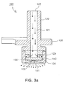
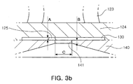
- FIGs. 3a and 3b are side sectional views of the sterilizing water dispensing apparatus according to an exemplary embodiment of the present invention.
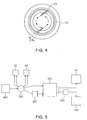
- FIG. 4 is a bottom view of a body part of the sterilizing water dispensing apparatus according to an exemplary embodiment of the present invention.
- FIG. 5 illustrates the configuration of a water supply system of the sterilizing water dispensing apparatus according to an exemplary embodiment of the present invention
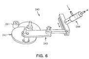
- FIG. 6 illustrates a different type of pump according to an exemplary embodiment of the present invention.
- FIG. 7 illustrates dispensing of sterilizing water to an inner wall of a toilet by the sterilizing water dispensing apparatus according to an exemplary embodiment of the present invention.
- FIG. 1 is a perspective view of a toilet 10 including a sterilizing water dispensing apparatus 100 according to an exemplary embodiment of the present invention.
- a bidet 20 is installed at an upper portion of the toilet 10.
- the bidet 20 includes a main body 30 of the bidet apparatus, and a toilet seat 40 and a toilet cover 50 are hinge-coupled to the main body 30 of the bidet apparatus such that they are rotatable.
- the toilet seat 40 has an annular shape to allow a user to be seated to have a bowel movement, and a heater may be disposed within the toilet seat 40 to heat the toilet seat 40 to have a temperature comfortable for a user.
- the toilet cover 50 is formed to have a shape corresponding to the toilet seat 40 in order to close the exposed portion of the annular toilet seat 40 when the toilet 10 is not in use.
- a nozzle assembly 60 and a drying apparatus 70 are installed at an inner side of the main body 30 of the bidet apparatus.
- the nozzle assembly 60 includes an anus cleaning nozzle and a for-women bidet nozzle.
- the cleaning nozzle and the bidet nozzle are installed to be movable in a forward direction from the main body 30 of the bidet apparatus.
- a nozzle tip having a discharge hole is mounted at a front end portion of each of the cleaning nozzle and the bidet nozzle to dispense flushing water.
- the drying apparatus 70 includes a blow fan, a blow duct, and a heating unit, and discharges heated air in a forward direction from the main body 30 of the bidet apparatus.
- a control panel 80 is installed at one side of the main body 30 of the bidet apparatus, so the user can control the operation of the bidet 20 by using the control panel 80. Namely, after having a bowel movement, the user may press a cleaning button or a bidet button. The cleaning nozzle or the bidet nozzle then moves forward to dispense water to the private parts of the user, and after cleaning, the user may press a drying button to dispense heated air to remove moisture from the private parts of the user.
- the sterilizing water dispensing apparatus 100 is installed at a front portion of the main body 30 of the bidet apparatus.
- the sterilizing water dispensing apparatus 100 receives sterilizing water from a sterilizing water generating apparatus, and dispenses the sterilizing water to an inner wall of the toilet 10 to sterilize the inner wall of the toilet 10.
- the sterilizing water dispensing apparatus 100 is preferably mounted at the main body 30 of the bidet apparatus such that a dispensing hole is sloped from a direct downward direction toward a front side of the toilet 10. By making the dispensing hole positioned at a rear side of the toilet 10 point towards the front side, sterilizing water can be dispensed evenly on the entire inner wall of the toilet 10.
- the dispensing hole is preferably installed to be sloped at more than 20 degrees in a forward direction.
- the sterilizing water dispensing apparatus 100 may be installed to be movable in a forward direction from the main body 30 of the bidet apparatus like the bidet nozzle, and in this case, the dispensing hole may not need to be installed to be sloped toward the front side.
- the sterilizing water dispensing apparatus 100 may execute a dispensing operation by means of the control panel 80. Namely, a toilet sterilization button may be provided to the control panel 80, so that when the user presses the toilet sterilization button, the sterilizing water dispensing apparatus 100 can dispense sterilizing water.
- FIG. 2 is an exploded perspective view of the sterilizing water dispensing apparatus 100 according to an exemplary embodiment of the present invention
- FIGs. 3a and 3b are side sectional views of the sterilizing water dispensing apparatus 100 according to an exemplary embodiment of the present invention
- FIG. 4 is a bottom view of a body part of the sterilizing water dispensing apparatus 100 according to an exemplary embodiment of the present invention.
- the sterilizing water dispensing apparatus 100 includes a body part 120 and a nozzle part 140.
- the body part 120 includes a hollow part 121 through which sterilizing water can flow, an inlet 122 formed at an upper end thereof, and an outlet 123 formed at a lower portion thereof. Sterilizing water which has introduced through the inlet 122 formed at the upper end of the body part 120 flows along the hollow part 121 and then is discharged through the outlet 123.
- the hollow part 121 extends in a lengthwise direction from the upper portion of the body part 120 to the lower portion of the body part 120, and the outlet 123 extends in a radial direction from the lower portion of the body part 120 so as to be fluid-connected with the hollow part 121. Accordingly, the sterilizing water flows from the upper portion to the lower portion of the hollow part 121 and then is discharged in the radial direction.
- a plurality of outlets 123 may be formed along the lower circumference of the body part 120, and in the present exemplary embodiment illustrated in the drawings, two outlets 123 are disposed in a facing manner.
- a protruding part 124 is formed at a lower side of the outlet 123, namely, at the lowermost portion of the body part 120.
- the protruding part 124 has a diameter larger than the part the outlet 123 is formed on.
- the protruding part 124 in a cylindrical shape has a recessed bottom surface to form a vortex production chamber 130 together with the nozzle part 140.
- a guide groove 125 is formed at a side wall of the protruding part 124 to allow sterilizing water which has been discharged through the outlet 123 to be introduced therein.
- the guide groove 125 starting from the side wall of the protruding part 124, extends to the interior of the protruding part 124, and is formed to point toward a position deviating from the center of the protruding part 124.
- This configuration aims to providing a rotational force to the sterilizing water introduced along the guide groove 125 to thus produce a vortex.
- the guide groove 125 is formed such that its width narrows toward the interior from the side wall. Accordingly, the sterilizing water introduced into the vortex production chamber 130 along the guide groove 125 can flow at a high pressure and at high speed to produce a strong vortex.
- a plurality of guide grooves 125 may be formed, and in the present exemplary embodiment illustrated in the drawings, two guide grooves 125 are formed in a facing manner.
- a bracket 126 is installed on the body part 120 and coupled to a front portion of the main body 30 of the bidet apparatus with a screw or the like.
- the nozzle part 140 having a cylindrical shape, is a member coupled to the lower portion of the body part 120.
- a dispensing hole 141 is formed at the center of the bottom of the nozzle part 140.
- An inner side of the bottom of the nozzle part 140 forms the vortex production chamber 130 together with the recessed portion of the protruding part 124.
- An outer portion of the bottom of the nozzle part 140 may be formed to be tapered such that the thickness increases as it goes away from the dispensing hole 141.
- the reason for forming the tapered outer portion of bottom of the nozzle part 140 is due to the fact that the length (B) of the dispensing hole 141 needs to be short in order to increase a dispensing angle for dispensing sterilizing water (to be described) and, in this case, if the thickness of the entire bottom of the nozzle part 140 is as small as to be equal to the length (B) of the dispensing hole 141, the rigidity of the bottom of the nozzle part 140 weakens, so the length (B) of the dispensing hole 141 remains short while the thickness of the outer portion of the bottom of the nozzle part 140 increases toward the outer side.
- Sterilizing water introduced through the inlet 122 at the upper end of the body part 120 passes along the hollow part 121 and is then discharged in the radial direction of the body part 120 through the outlet 123 provided at the lower portion of the body part 120.
- the sterilizing water which has been discharged through the outlet 123 is introduced into the vortex production chamber 130 along the guide grooves 125 of the protruding part 124 formed at the lowermost portion of the body part 120.
- the guide groove 125 is formed to extend in a direction other than towards the center of the vortex production chamber 130 from the side wall of the vortex production chamber 130, so the sterilizing water introduced along the guide groove 125 forms a rotating vortex centered on the center of the vortex production chamber 130.
- the sterilizing water flowing along the guide grooves 125 can flow at a high pressure and at a high speed to form a strong vortex.
- the plurality of guide grooves 125 are disposed to face each other, vortexes are produced from two places, complementing each other.
- the sterilizing water with the vortexes produced in the vortex production chamber 130 is externally discharged through the dispensing hole 141 disposed at the center of the bottom of the nozzle part 140. At this time, the externally discharged sterilizing water, namely, the vortex-formed sterilizing water, passes through the dispensing hole 141 at a high pressure, to become fine particles being sprayed to the outer side.
- the sterilizing water when the sterilizing water is sprayed in the form of fine particles with a large surface area, the sterilizing water can be brought into contact with a larger area of the inner wall of the toilet, having the advantage of enhancing the sterilizing effect even with the small quantity of sterilizing water.
- the single sterilizing water dispensing apparatus 100 in order to spray the sterilizing water to the entire surface of the inner wall of the toilet 10 by using the single sterilizing water dispensing apparatus 100, it is required to properly set a dispensing angle and a dispensing speed of the sterilizing water dispensed from the dispensing hole 141. Namely, as the dispensing angle widens and the dispensing speed becomes high, sterilizing water can be dispensed widely, and if the dispensing angle is small, the dispensing range is reduced to perform partial dispensing, while if the dispensing speed is low, the dispensed sterilizing water could not extend for a desirable distance (i.e., it could not reach sufficiently far).
- the dispensing angle and dispensing speed of sterilizing water needs to be increased so that the sterilizing water can be dispensed to the entire surface of the inner wall of the toilet 10, for which the sterilizing water dispensing apparatus 100 must be thus optimally designed.
- the inventors of the present invention found through an experimentation that the height (A) of the vortex production chamber 130, the length (B) of the dispensing hole 141, the diameter (C) of the dispensing hole 141, and the width (D) of the guide groove 125 are parameters affecting the dispensing angle and the dispensing speed.
- the first case shows the largest dispensing angle and the highest dispensing speed.
- the second case when the diameter (C) of the dispensing hole 141 was increased, the dispensing angle was reduced and the dispensing speed was lowered.
- the third case when the height (A) of the vortex production chamber 130 was increased, the dispensing angle was reduced and the dispensing speed was lowered.
- the fourth to sixth cases when the length (B) of the dispensing hole 141 was increased, the dispensing angle was further reduced and the dispensing speed was further lowered. Consequently, it should be noted that as the parameters A, B, and C are reduced, the dispensing angle and the dispensing speed are increased, establishing inverse proportional relationships.
- the dispensing angle is 100 degrees or greater and the dispensing range is 90% or greater of the inner wall of the toilet, until when A is 0.3 mm or smaller, while if A is 0.5 mm, the dispensing angle is 20 degrees or lower and the dispensing range is smaller than 10%.
- A in order to make the dispensing angle 100 degrees or greater and the dispensing range 90% or greater, A must be 0.3 mm or smaller.
- the dispensing angle is 100 degrees or greater and the dispensing range is 90% or greater of the inner wall of the toilet until when B is 0.3 mm or smaller, while if B is 0.5 mm or greater, the dispensing angle is 20 degrees or lower and the dispensing range is smaller than 10%.
- B in order to make the dispensing angle 100 degrees or greater and the dispensing range 90% or greater, B must be 0.3 mm or smaller.
- the dispensing angle is 100 degrees or greater and the dispensing range is 90% or greater of the inner wall of the toilet until when C is 1.5 mm or smaller, while if C is 1.7 mm, the dispensing angle is 20 degrees or lower and the dispensing range is smaller than 10%.
- C in order to make the dispensing angle 100 degrees or greater and the dispensing range 90% or greater, C must be 1.5 mm or smaller.
- the dispensing angle is 100 degrees or greater and the dispensing range is 90% or greater of the inner wall of the toilet until when D is 0.7 mm or smaller, while if D is 1 mm, the dispensing angle is 20 degrees or lower and the dispensing range is smaller than 10%.
- D in order to make the dispensing angle 100 degrees or greater and the dispensing range 90% or greater, D must be 0.7 mm or smaller.
- the dispensing angle is 140 degrees or greater and the dispensing range is 99% of the inner wall of the toilet.
- the dispensing angle is 20 degrees or smaller and the dispensing range is smaller than 10% of the inner wall of the toilet.
- the denotation of an abnormal water stream refers to a case that water is twisted to be dispensed, having a very small dispensing range.
- the height (A) of the vortex production chamber 130 must be 0.3 mm or smaller
- the length (B) of the dispensing hole 141 must be 0.3 mm or smaller
- the diameter (C) of the dispensing hole 141 must be 1.5 mm or smaller
- the width (D) of the guide groove 125 must be 0.7 mm or smaller.
- the dispensing angle can be increased by reducing the parameters, but in consideration of molding limitations and costs, the fabrication of a dispensing hole with the parameters A, B, C, and D of 0.1 mm or smaller is not easy, and if realized, there is not a great deal of difference in its effects.
- the above experimental results can be obtained when the pressure of sterilizing water within the vortex production chamber 130 is 1.2 kg/cm 2 or greater. That is, such large dispensing angle and dispensing range as in the experimental results cannot be obtained at a lower pressure.
- the size of the dispensing hole 141 is designed to be smaller than the inlet 122. In this case, however, sterilizing water having an excessively high pressure would lead to damage to the components, so the pressure of the sterilizing water preferably does not exceed 5 kg/cm 2 .
- FIG. 5 illustrates the configuration of a water supply system of the sterilizing water dispensing apparatus 100 according to an exemplary embodiment of the present invention.
- the water supply system is configured to distribute source water to each element through a flow path control apparatus 300.
- the source water may be supplied by a water pipe or a water supply tank 400.
- the source water is supplied to the cleaning nozzle 62 or the bidet nozzle 64, and flush water is dispensed through the nozzle.
- the source water is supplied to the sterilizing water generating apparatus 200, in which the source water becomes sterilizing water.
- the sterilizing water is supplied to a nozzle tip cleaning part 66.
- the sterilizing water of the nozzle tip cleaning part 66 is applied to the nozzle tip, and the nozzle tip is sterilized.
- the source water is supplied to the sterilizing water generating apparatus 200, in which the source water becomes sterilizing water.
- a pump 240 connected with the sterilizing water generating apparatus 200 operates to allow the sterilizing water to be introduced into the sterilizing water dispensing apparatus 100.
- the sterilizing water introduced into the sterilizing water dispensing apparatus 100 is dispensed to the inner wall of the toilet 10, sterilizing the toilet 10.
- the process of dispensing the sterilizing water in the spray form by the sterilizing water dispensing apparatus 100 is as described above.
- the sterilizing water dispensing apparatus 100 sprays the sterilizing water in the form of fine particles, only a small quantity of sterilizing water (e.g. , about 50 ml of sterilizing water) is required to sterilize the entire inner wall of the toilet.
- a small quantity of sterilizing water e.g. , about 50 ml of sterilizing water
- the use of a low capacity pump is sufficient and, for example, a low-noise high-lift diaphragm type pump may be employed.
- FIG. 6 illustrates a different type of pump 240 according to an exemplary embodiment of the present invention.
- the pump 240 includes a deceleration gear part 242 coupled to an electric motor 241 and having a plurality of gears to decelerate a rotational speed of the electric motor 241, and a plurality of link members 243 having one side coupled to the deceleration gear part 242 and make a joint movement.
- the pump 240 further includes a pumping unit 244 provided at the other side of the link member 243 and making a reciprocal movement according to the joint movement of the link member 243.
- the pumping unit 244 instantly pumps sterilizing water from the sterilizing water generating apparatus 200 while making the reciprocal movement, and supplies it to the sterilizing water dispensing apparatus 100. In this manner, when the sterilizing water is supplied by instantly applying pressure to the sterilizing water dispensing apparatus 100, the sterilizing water which has passed through the sterilizing water dispensing apparatus 100 can be sprayed as particles in a fine size through the dispensing hole 141.
- the sterilizing water generating apparatus 200 may use an electrode-type module that generates a sterilization material (mixed oxide: MO) from water itself by using an electric force and a ruthenium oxide catalyst electrode.
- a sterilization material mixed oxide: MO
- MO mixed oxide
- a reactive material adding unit 220 may be connected to an inflow side of the sterilizing water generating apparatus 200.
- the reactive material adding unit 220 may add a reactive material to water introduced into the sterilizing water generating apparatus 200 to increase the amount of a sterilizing material generated in the sterilizing water generating apparatus 200.
- Solid NaCl may be used as the reactive material.
- the reactive material is accommodated within the reactive material adding unit 220, mixed with water introduced to the interior of the reactive material adding unit 220, and then introduced to the sterilizing water generating apparatus 200.
- the sterilizing water generating apparatus 200 applies electricity to the NaCl-mixed water to generate HOCL - or OCL - ions, a sterilizing material.
- NaCl NaCl
- chlorine-based material silver oxide
- iodine-based material and the like, may be introduced into the sterilizing water generating apparatus 200.
- FIG. 7 illustrates the dispensing of sterilizing water to the inner wall of the toilet by the sterilizing water dispensing apparatus 100 according to an exemplary embodiment of the present invention.
- the sterilizing water dispensing apparatus 100 attached to the front portion of the main body 30 of the bidet apparatus sprays sterilizing water at a wide dispensing angle to apply the sterilizing water to the entire surface of the inner wall of the toilet 10.
- the sterilizing water dispensing apparatus 100 and the sterilizing water generating apparatus 200 are installed at the bidet 20, but without being limited thereto, they may be installed at the toilet seat 40 and used. That is, the sterilizing water dispensing apparatus 100 and the sterilizing water generating apparatus 200 may be installed at a rear portion of the toilet seat 40, and likewise as in the case where they are installed at the bidet 20, preferably, the dispensing hole 141 is installed to be sloped forwardly at 20 degrees or greater from the direct downward direction. In addition, because electricity is not generally supplied to toilet seat 40, the sterilizing water generating apparatus 200 that generates sterilizing water according to a solution method.
- a product manufactured by combining the sterilizing water dispensing apparatus to a toilet seat can be advantageously used for those users who want a toilet sterilization function although they do not use a bidet.
- sterilizing water is dispensed in the form of fine particles with a relatively large surface area, the sterilizing water is brought into contact with a larger area of an inner wall of a toilet, so a sterilizing effect can be enhanced with a small quantity of sterilizing water.
- sterilizing water can be dispensed to the entire surface of the inner wall of the toilet with a single sterilizing water dispensing apparatus by increasing a dispensing angle and dispensing speed of sterilizing water, the configuration can be simple and the cost can be reduced.
Landscapes
- Health & Medical Sciences (AREA)
- Life Sciences & Earth Sciences (AREA)
- Engineering & Computer Science (AREA)
- Hydrology & Water Resources (AREA)
- Public Health (AREA)
- Water Supply & Treatment (AREA)
- Bidet-Like Cleaning Device And Other Flush Toilet Accessories (AREA)
- Apparatus For Disinfection Or Sterilisation (AREA)
- Toilet Supplies (AREA)
Description
- The present invention relates to a toilet comprising a bidet that comprises a nozzle assembly that dispenses water to the private parts of a user and a cleaning water dispensing apparatus for dispensing cleaning water to an inner wall of the toilet.
- A toilet (i.e., a toilet bowel, a chamber pot, etc.) is equipment allowing a user to be seated to have a bowel movement, and recently, a bidet-equipped toilet has been widely used for a sanitary purpose. A bidet is a device for dispensing water to cleanse the private parts of the user after the user relieves himself, having the advantage of keeping the private parts of the user clean through washing without the use of paper.
- Commonly, a water tank, a bidet, and a control panel are mounted on the toilet. Upon completion of a bowel movement, when the user presses a lever, water within the toilet is flushed out, along with feces, and the toilet is refilled with water from that contained within the water tank. In addition, when the user operates the bidet by manipulating the control panel, a nozzle installed within a main body of the bidet apparatus moves to a front side of the main body of the bidet apparatus to dispense cleansing water to the private parts of the user.
- With the toilet operating in this manner, if the feces within the toilet are not entirely flushed out, the feces may be fixedly attached to an inner wall of the toilet. In addition, because water is always present within the toilet, various microorganisms may inhabit it and multiply, which is undesirable in terms of sanitation. Thus, the user must periodically wash the toilet by applying a sterilization solution or cleaning solution to the interior of the toilet.
-
WO 03/102315 -
US 2001/022006 A1 discloses a bidet and toilet seat comprising a nozzle pipe washer, and a water tank and changeover valve for supplying water to the nozzle pipe washer, which has an inlet for the water. Both spiral and straight bores are provided in the nozzle pipe washer to provide the water discharged from an ejecting outlet with a spiral component. However, the nozzle pipe washer ofUS 2001/022006 A1 is configured and arranged for cleaning one or more nozzle pipes of the bidet or toilet seat, which nozzle pipes are provided for cleaning private parts of a user. Some of the water may come into contact with the inner wall of a toilet, but the nozzle pipe washer is not intended for cleaning of an inner wall of a toilet onto which the bidet or toilet seat is provided. The water discharged from the ejecting outlet will predominantly be forwardly directed along the nozzle pipe washer towards the nozzle pipes to be cleaned. -
GB 1 562 052 GB 1 562 052 -
EP 0 000 688 A2 discloses a nozzle for dispensing a fluid under pressure, such as hair spray, deodorant and odour remover. However, the nozzle receives water from the outlet in lengthwise direction such that it is not discharged in radial direction towards the wall of the surrounding nozzle wall forming the vortex production chamber. - The present invention provides a toilet comprising a sterilizing water dispensing apparatus capable of sterilizing the entire inner wall of a toilet with a small quantity of sterilizing water.
- According to the invention, there is provided a toilet according to claim 1. The fine particles of sterilizing water do effectively reach all areas of the inner wall of the toilet for disinfecting purposes.
- The sterilizing water in the vortex production chamber may be sprayed in the form of fine particles through the dispensing hole.
- The guide groove is formed such that its width narrows toward the interior from the side wall.
- A plurality of guide grooves may be formed to be symmetrical about the center of the vortex production chamber.
- Sterilizing water may be dispensed through the dispensing hole at a dispensing angle of 100 degrees or greater.
- The vortex production chamber may have a height (A) ranging from 0.1 mm to 0.3mm.
- The dispensing hole may have a length (B) ranging from 0.1 mm to 0.3 mm.
- The dispensing hole may have a diameter (C) ranging from 0.1 mm to 1.5 mm.
- The guide groove may have a width (D) ranging from 0.1 mm to 0.7 mm.
- The dispensing hole may be smaller than the inlet.
- The pressure of sterilizing water within the vortex production chamber may range 1.2 kg/cm2 to 5 kg/cm2.
- The sterilizing water generating apparatus may generate sterilizing water by an electrode method.
- The toilet may further include a nozzle tip cleaning part that cleans a nozzle tip of the nozzle assembly, wherein the sterilizing water generating apparatus is connected to the sterilizing water dispensing apparatus and the nozzle tip cleaning part, and sterilizing water generated by the sterilizing water generating apparatus is supplied to the sterilizing water dispensing apparatus or to the nozzle tip cleaning part.
- The sterilizing water dispensing apparatus may be connected to a pump, and sterilizing water may be supplied by the pump.
- The pump may include an electric motor, a decelerating gear part connected with the electric motor and having a plurality of gears to decelerate a rotational speed, a plurality of link members having one side coupled with the decelerating gear part and making a joint movement, and a pumping unit connected with another side of the link members and reciprocally moving according to the joint movement of the link member, wherein the pumping unit may supply sterilizing water of the sterilizing water generating apparatus to the sterilizing water dispensing apparatus while making a reciprocal movement.
- A dispensing hole of the sterilizing water dispensing apparatus may be installed to be sloped from a directly downward side to a front side.
- The toilet may be provided with a toilet seat including the sterilizing water dispensing apparatus, and the sterilizing water generating apparatus that supplies sterilizing water to the sterilizing water dispensing apparatus.
- The sterilizing water generating apparatus may generate sterilizing water by a solution method.
- The sterilizing water dispensing apparatus may be installed at a rear side of the toilet seat, and a dispensing hole may be installed to be sloped from a directly downward side to a front side.
- The above and other aspects, features and other advantages of the present invention will be more clearly understood from the following detailed description taken in conjunction with the accompanying drawings, in which:
-
FIG. 1 is a perspective view of a toilet including a sterilizing water dispensing apparatus according to an exemplary embodiment of the present invention; -
FIG. 2 is an exploded perspective view of the sterilizing water dispensing apparatus according to an exemplary embodiment of the present invention; -
FIGs. 3a and3b are side sectional views of the sterilizing water dispensing apparatus according to an exemplary embodiment of the present invention; -
FIG. 4 is a bottom view of a body part of the sterilizing water dispensing apparatus according to an exemplary embodiment of the present invention; -
FIG. 5 illustrates the configuration of a water supply system of the sterilizing water dispensing apparatus according to an exemplary embodiment of the present invention; -
FIG. 6 illustrates a different type of pump according to an exemplary embodiment of the present invention; and -
FIG. 7 illustrates dispensing of sterilizing water to an inner wall of a toilet by the sterilizing water dispensing apparatus according to an exemplary embodiment of the present invention. - Exemplary embodiments of the present invention will now be described in detail with reference to the accompanying drawings. The invention may, however, be embodied in many different forms and should not be construed as limited to the embodiments set forth herein. Rather, these embodiments are provided so that this disclosure will be thorough and complete, and will fully convey the scope of the invention to those skilled in the art. In the drawings, the shapes and dimensions may be exaggerated for clarity, and the same reference numerals will be used throughout to designate the same or like components.
-
FIG. 1 is a perspective view of atoilet 10 including a sterilizingwater dispensing apparatus 100 according to an exemplary embodiment of the present invention. - With reference to
FIG. 1 , abidet 20 is installed at an upper portion of thetoilet 10. Thebidet 20 includes amain body 30 of the bidet apparatus, and atoilet seat 40 and atoilet cover 50 are hinge-coupled to themain body 30 of the bidet apparatus such that they are rotatable. Thetoilet seat 40 has an annular shape to allow a user to be seated to have a bowel movement, and a heater may be disposed within thetoilet seat 40 to heat thetoilet seat 40 to have a temperature comfortable for a user. Thetoilet cover 50 is formed to have a shape corresponding to thetoilet seat 40 in order to close the exposed portion of theannular toilet seat 40 when thetoilet 10 is not in use. - A
nozzle assembly 60 and a dryingapparatus 70 are installed at an inner side of themain body 30 of the bidet apparatus. Thenozzle assembly 60 includes an anus cleaning nozzle and a for-women bidet nozzle. The cleaning nozzle and the bidet nozzle are installed to be movable in a forward direction from themain body 30 of the bidet apparatus. A nozzle tip having a discharge hole is mounted at a front end portion of each of the cleaning nozzle and the bidet nozzle to dispense flushing water. - The drying
apparatus 70 includes a blow fan, a blow duct, and a heating unit, and discharges heated air in a forward direction from themain body 30 of the bidet apparatus. - A
control panel 80 is installed at one side of themain body 30 of the bidet apparatus, so the user can control the operation of thebidet 20 by using thecontrol panel 80. Namely, after having a bowel movement, the user may press a cleaning button or a bidet button. The cleaning nozzle or the bidet nozzle then moves forward to dispense water to the private parts of the user, and after cleaning, the user may press a drying button to dispense heated air to remove moisture from the private parts of the user. - The sterilizing
water dispensing apparatus 100 is installed at a front portion of themain body 30 of the bidet apparatus. The sterilizingwater dispensing apparatus 100 receives sterilizing water from a sterilizing water generating apparatus, and dispenses the sterilizing water to an inner wall of thetoilet 10 to sterilize the inner wall of thetoilet 10. The sterilizingwater dispensing apparatus 100 is preferably mounted at themain body 30 of the bidet apparatus such that a dispensing hole is sloped from a direct downward direction toward a front side of thetoilet 10. By making the dispensing hole positioned at a rear side of thetoilet 10 point towards the front side, sterilizing water can be dispensed evenly on the entire inner wall of thetoilet 10. In this respect, in consideration of the general size of thetoilet 10 and mounting position of the sterilizingwater dispensing apparatus 100, the dispensing hole is preferably installed to be sloped at more than 20 degrees in a forward direction. Alternatively, the sterilizingwater dispensing apparatus 100 may be installed to be movable in a forward direction from themain body 30 of the bidet apparatus like the bidet nozzle, and in this case, the dispensing hole may not need to be installed to be sloped toward the front side. Meanwhile, the sterilizingwater dispensing apparatus 100 may execute a dispensing operation by means of thecontrol panel 80. Namely, a toilet sterilization button may be provided to thecontrol panel 80, so that when the user presses the toilet sterilization button, the sterilizingwater dispensing apparatus 100 can dispense sterilizing water. -
FIG. 2 is an exploded perspective view of the sterilizingwater dispensing apparatus 100 according to an exemplary embodiment of the present invention,FIGs. 3a and3b are side sectional views of the sterilizingwater dispensing apparatus 100 according to an exemplary embodiment of the present invention, andFIG. 4 is a bottom view of a body part of the sterilizingwater dispensing apparatus 100 according to an exemplary embodiment of the present invention. - With reference to
FIGs. 2 to 4 , the sterilizingwater dispensing apparatus 100 includes abody part 120 and anozzle part 140. - The
body part 120 includes ahollow part 121 through which sterilizing water can flow, aninlet 122 formed at an upper end thereof, and anoutlet 123 formed at a lower portion thereof. Sterilizing water which has introduced through theinlet 122 formed at the upper end of thebody part 120 flows along thehollow part 121 and then is discharged through theoutlet 123. - The
hollow part 121 extends in a lengthwise direction from the upper portion of thebody part 120 to the lower portion of thebody part 120, and theoutlet 123 extends in a radial direction from the lower portion of thebody part 120 so as to be fluid-connected with thehollow part 121. Accordingly, the sterilizing water flows from the upper portion to the lower portion of thehollow part 121 and then is discharged in the radial direction. A plurality ofoutlets 123 may be formed along the lower circumference of thebody part 120, and in the present exemplary embodiment illustrated in the drawings, twooutlets 123 are disposed in a facing manner. - A
protruding part 124 is formed at a lower side of theoutlet 123, namely, at the lowermost portion of thebody part 120. The protrudingpart 124 has a diameter larger than the part theoutlet 123 is formed on. The protrudingpart 124 in a cylindrical shape has a recessed bottom surface to form avortex production chamber 130 together with thenozzle part 140. Aguide groove 125 is formed at a side wall of theprotruding part 124 to allow sterilizing water which has been discharged through theoutlet 123 to be introduced therein. Theguide groove 125, starting from the side wall of theprotruding part 124, extends to the interior of theprotruding part 124, and is formed to point toward a position deviating from the center of theprotruding part 124. This configuration aims to providing a rotational force to the sterilizing water introduced along theguide groove 125 to thus produce a vortex. Theguide groove 125 is formed such that its width narrows toward the interior from the side wall. Accordingly, the sterilizing water introduced into thevortex production chamber 130 along theguide groove 125 can flow at a high pressure and at high speed to produce a strong vortex. A plurality ofguide grooves 125 may be formed, and in the present exemplary embodiment illustrated in the drawings, twoguide grooves 125 are formed in a facing manner. - A
bracket 126 is installed on thebody part 120 and coupled to a front portion of themain body 30 of the bidet apparatus with a screw or the like. - The
nozzle part 140, having a cylindrical shape, is a member coupled to the lower portion of thebody part 120. A dispensinghole 141 is formed at the center of the bottom of thenozzle part 140. An inner side of the bottom of thenozzle part 140 forms thevortex production chamber 130 together with the recessed portion of theprotruding part 124. An outer portion of the bottom of thenozzle part 140 may be formed to be tapered such that the thickness increases as it goes away from the dispensinghole 141. The reason for forming the tapered outer portion of bottom of thenozzle part 140 is due to the fact that the length (B) of the dispensinghole 141 needs to be short in order to increase a dispensing angle for dispensing sterilizing water (to be described) and, in this case, if the thickness of the entire bottom of thenozzle part 140 is as small as to be equal to the length (B) of the dispensinghole 141, the rigidity of the bottom of thenozzle part 140 weakens, so the length (B) of the dispensinghole 141 remains short while the thickness of the outer portion of the bottom of thenozzle part 140 increases toward the outer side. - The operation method of the sterilizing
water dispensing apparatus 100 configured thusly will now be described. - Sterilizing water introduced through the
inlet 122 at the upper end of thebody part 120 passes along thehollow part 121 and is then discharged in the radial direction of thebody part 120 through theoutlet 123 provided at the lower portion of thebody part 120. The sterilizing water which has been discharged through theoutlet 123 is introduced into thevortex production chamber 130 along theguide grooves 125 of theprotruding part 124 formed at the lowermost portion of thebody part 120. Theguide groove 125 is formed to extend in a direction other than towards the center of thevortex production chamber 130 from the side wall of thevortex production chamber 130, so the sterilizing water introduced along theguide groove 125 forms a rotating vortex centered on the center of thevortex production chamber 130. In particular, because the width of theguide groove 125 is reduced toward the inner side, the sterilizing water flowing along theguide grooves 125 can flow at a high pressure and at a high speed to form a strong vortex. In addition, because the plurality ofguide grooves 125 are disposed to face each other, vortexes are produced from two places, complementing each other. The sterilizing water with the vortexes produced in thevortex production chamber 130 is externally discharged through the dispensinghole 141 disposed at the center of the bottom of thenozzle part 140. At this time, the externally discharged sterilizing water, namely, the vortex-formed sterilizing water, passes through the dispensinghole 141 at a high pressure, to become fine particles being sprayed to the outer side. - In this manner, when the sterilizing water is sprayed in the form of fine particles with a large surface area, the sterilizing water can be brought into contact with a larger area of the inner wall of the toilet, having the advantage of enhancing the sterilizing effect even with the small quantity of sterilizing water.
- Meanwhile, in order to spray the sterilizing water to the entire surface of the inner wall of the
toilet 10 by using the single sterilizingwater dispensing apparatus 100, it is required to properly set a dispensing angle and a dispensing speed of the sterilizing water dispensed from the dispensinghole 141. Namely, as the dispensing angle widens and the dispensing speed becomes high, sterilizing water can be dispensed widely, and if the dispensing angle is small, the dispensing range is reduced to perform partial dispensing, while if the dispensing speed is low, the dispensed sterilizing water could not extend for a desirable distance (i.e., it could not reach sufficiently far). - Thus, the dispensing angle and dispensing speed of sterilizing water needs to be increased so that the sterilizing water can be dispensed to the entire surface of the inner wall of the
toilet 10, for which the sterilizingwater dispensing apparatus 100 must be thus optimally designed. The inventors of the present invention found through an experimentation that the height (A) of thevortex production chamber 130, the length (B) of the dispensinghole 141, the diameter (C) of the dispensinghole 141, and the width (D) of theguide groove 125 are parameters affecting the dispensing angle and the dispensing speed. - In order to discover the influence of these parameters on the dispensing angle and the dispensing speed, the inventors conducted CFD (Computational Fluid Dynamics) research with respect to diverse parameter values, the results of which are as follows.
Table Case A (mm) B (mm) C (mm) D (mm) Dispensing angle (degree) Dispensing speed (m/s) 1 0.2 0.2 1 0.5 140 5.562 2 0.2 0.2 1.2 0.5 120 5.128 3 0.3 0.2 1 0.5 100 4.483 4 0.3 0.6 1 0.5 90 4.163 5 0.2 0.6 1.2 0.5 70 3.213 6 0.2 0.6 1 0.5 - 2.110 - With reference to the above table, the first case shows the largest dispensing angle and the highest dispensing speed. In the second case, when the diameter (C) of the dispensing
hole 141 was increased, the dispensing angle was reduced and the dispensing speed was lowered. In the third case, when the height (A) of thevortex production chamber 130 was increased, the dispensing angle was reduced and the dispensing speed was lowered. In the fourth to sixth cases, when the length (B) of the dispensinghole 141 was increased, the dispensing angle was further reduced and the dispensing speed was further lowered. Consequently, it should be noted that as the parameters A, B, and C are reduced, the dispensing angle and the dispensing speed are increased, establishing inverse proportional relationships. - Based on the results that the dispensing angle and the dispensing speed are inverse-proportional to the parameter values, in order to determine the upper limits of the parameters with which the dispensing angle and the dispensing speed can be larger than a certain value (e.g., the dispensing angle of at least 100 degrees), the inventor of the present invention conducted actual experimentation, the results of which are shown in the table below:
Table A (mm) B (mm) C (mm) D (mm) Dispensing angle Dispensing range 1 0.1 0.1 1 0.5 140 degrees or greater 99% or greater 2 0.2 0.2 1 0.5 100 degrees or greater 90% or greater 3 0.3 0.2 1 0.5 100 degrees or greater 90% or greater 4 0.5 0.2 1 0.5 20 degrees or smaller Smaller than 10% 5 0.5 0.1 1.2 0.5 20 degrees or smaller Smaller than 10% 6 0.2 0.3 1 0.5 100 degrees or greater 90% or greater 7 0.2 0.5 1 0.5 20 degrees of smaller Smaller than 10% 8 0.2 1 1 0.5 Abnormal water stream Smaller than 10% 9 0.5 1 1 0.5 Abnormal water stream Smaller than 10% 10 0.2 1 1.2 0.5 Abnormal water stream Smaller than 10% 11 0.5 1 1.2 0.5 20 degrees or smaller Smaller than 10% 12 0.2 0.2 1.2 0.5 100 degrees or greater 90% or greater 13 0.2 0.2 1.5 0.5 100 degrees or greater 90% or greater 14 0.2 0.2 1.7 0.5 20 degrees or smaller Smaller than 10% 15 0.2 0.2 1 0.7 100 degrees or greater 90% or greater 16 0.2 0.2 1 1 20 degrees or smaller 0% 17 0.2 0.2 1.2 1 20 degrees or smaller Smaller than 10% 18 0.5 0.2 1 1 20 degrees or smaller 0% 19 0.5 0.1 1.2 1 20 degrees or smaller Smaller than 10% 20 0.2 1 1.2 1 20 degrees or smaller Smaller than 10% - With reference to the second to fourth cases in the above table, it is noted that, when B, C, and D are the same, the dispensing angle is 100 degrees or greater and the dispensing range is 90% or greater of the inner wall of the toilet, until when A is 0.3 mm or smaller, while if A is 0.5 mm, the dispensing angle is 20 degrees or lower and the dispensing range is smaller than 10%. Thus, in order to make the dispensing
angle 100 degrees or greater and the dispensing range 90% or greater, A must be 0.3 mm or smaller. - With reference to the second, sixth to eighth cases in the above table, it is noted that, when A, C, and D are the same, the dispensing angle is 100 degrees or greater and the dispensing range is 90% or greater of the inner wall of the toilet until when B is 0.3 mm or smaller, while if B is 0.5 mm or greater, the dispensing angle is 20 degrees or lower and the dispensing range is smaller than 10%. Thus, in order to make the dispensing
angle 100 degrees or greater and the dispensing range 90% or greater, B must be 0.3 mm or smaller. - With reference to the second and 12th to 14th cases in the above table, it is noted that, when A, B, and D are the same, the dispensing angle is 100 degrees or greater and the dispensing range is 90% or greater of the inner wall of the toilet until when C is 1.5 mm or smaller, while if C is 1.7 mm, the dispensing angle is 20 degrees or lower and the dispensing range is smaller than 10%. Thus, in order to make the dispensing
angle 100 degrees or greater and the dispensing range 90% or greater, C must be 1.5 mm or smaller. - With reference to the second, 15th and 16th cases in the above Table, it is noted that, when A, B, and C are the same, the dispensing angle is 100 degrees or greater and the dispensing range is 90% or greater of the inner wall of the toilet until when D is 0.7 mm or smaller, while if D is 1 mm, the dispensing angle is 20 degrees or lower and the dispensing range is smaller than 10%. Thus, in order to make the dispensing
angle 100 degrees or greater and the dispensing range 90% or greater, D must be 0.7 mm or smaller. - With reference to the first case in the above table, it is noted that, when the parameters of A, B, C, and D are in the smallest range, the dispensing angle is 140 degrees or greater and the dispensing range is 99% of the inner wall of the toilet. However, in the fifth, ninth to 11th, and 17th to 20th cases, in which at least one of the parameters of A, B, C, and D exceeds the range, the dispensing angle is 20 degrees or smaller and the dispensing range is smaller than 10% of the inner wall of the toilet. For reference, the denotation of an abnormal water stream refers to a case that water is twisted to be dispensed, having a very small dispensing range.
- When the above results are put together, in order to obtain the dispensing angle of 100 degrees or greater and the dispensing range of 90% or greater, the height (A) of the
vortex production chamber 130 must be 0.3 mm or smaller, the length (B) of the dispensinghole 141 must be 0.3 mm or smaller, the diameter (C) of the dispensinghole 141 must be 1.5 mm or smaller, and the width (D) of theguide groove 125 must be 0.7 mm or smaller. - Meanwhile, the dispensing angle can be increased by reducing the parameters, but in consideration of molding limitations and costs, the fabrication of a dispensing hole with the parameters A, B, C, and D of 0.1 mm or smaller is not easy, and if realized, there is not a great deal of difference in its effects.
- In addition, the above experimental results can be obtained when the pressure of sterilizing water within the
vortex production chamber 130 is 1.2 kg/cm2 or greater. That is, such large dispensing angle and dispensing range as in the experimental results cannot be obtained at a lower pressure. In order to maintain the pressure of the sterilizing water within thevortex production chamber 130 at a certain level or greater, preferably, the size of the dispensinghole 141 is designed to be smaller than theinlet 122. In this case, however, sterilizing water having an excessively high pressure would lead to damage to the components, so the pressure of the sterilizing water preferably does not exceed 5 kg/cm2. -
FIG. 5 illustrates the configuration of a water supply system of the sterilizingwater dispensing apparatus 100 according to an exemplary embodiment of the present invention. - With reference to
FIG. 5 , the water supply system is configured to distribute source water to each element through a flow path controlapparatus 300. The source water may be supplied by a water pipe or awater supply tank 400. - When the user executes cleaning or the bidet function, the source water is supplied to the cleaning
nozzle 62 or thebidet nozzle 64, and flush water is dispensed through the nozzle. - When the user executes a nozzle tip cleaning function, the source water is supplied to the sterilizing
water generating apparatus 200, in which the source water becomes sterilizing water. The sterilizing water is supplied to a nozzletip cleaning part 66. The sterilizing water of the nozzletip cleaning part 66 is applied to the nozzle tip, and the nozzle tip is sterilized. - When the user executes a toilet cleaning function, the source water is supplied to the sterilizing
water generating apparatus 200, in which the source water becomes sterilizing water. When a desired quantity of sterilized water is generated with the lapse of a certain period of time, apump 240 connected with the sterilizingwater generating apparatus 200 operates to allow the sterilizing water to be introduced into the sterilizingwater dispensing apparatus 100. The sterilizing water introduced into the sterilizingwater dispensing apparatus 100 is dispensed to the inner wall of thetoilet 10, sterilizing thetoilet 10. The process of dispensing the sterilizing water in the spray form by the sterilizingwater dispensing apparatus 100 is as described above. - When the nozzle tip is to be cleaned, a small quantity of sterilizing water is simply allowed to flow to the nozzle tip under the pressure of the source water without using a pump, but when the toilet is to be sterilized, the sterilizing water must be sprayed across the entire inner wall of the toilet, so a pump is driven to spray the sterilizing water. In this case, however, as stated above, the sterilizing
water dispensing apparatus 100 according to an exemplary embodiment of the present invention sprays the sterilizing water in the form of fine particles, only a small quantity of sterilizing water (e.g. , about 50 ml of sterilizing water) is required to sterilize the entire inner wall of the toilet. Thus, the use of a low capacity pump is sufficient and, for example, a low-noise high-lift diaphragm type pump may be employed. -
FIG. 6 illustrates a different type ofpump 240 according to an exemplary embodiment of the present invention. With reference toFIG. 6 , thepump 240 includes adeceleration gear part 242 coupled to anelectric motor 241 and having a plurality of gears to decelerate a rotational speed of theelectric motor 241, and a plurality oflink members 243 having one side coupled to thedeceleration gear part 242 and make a joint movement. Thepump 240 further includes apumping unit 244 provided at the other side of thelink member 243 and making a reciprocal movement according to the joint movement of thelink member 243. Thepumping unit 244 instantly pumps sterilizing water from the sterilizingwater generating apparatus 200 while making the reciprocal movement, and supplies it to the sterilizingwater dispensing apparatus 100. In this manner, when the sterilizing water is supplied by instantly applying pressure to the sterilizingwater dispensing apparatus 100, the sterilizing water which has passed through the sterilizingwater dispensing apparatus 100 can be sprayed as particles in a fine size through the dispensinghole 141. - The sterilizing
water generating apparatus 200 may use an electrode-type module that generates a sterilization material (mixed oxide: MO) from water itself by using an electric force and a ruthenium oxide catalyst electrode. The generation of sterilizing water according to the electrode method is a known art, so a detailed description thereof will be omitted. - A reactive
material adding unit 220 may be connected to an inflow side of the sterilizingwater generating apparatus 200. The reactivematerial adding unit 220 may add a reactive material to water introduced into the sterilizingwater generating apparatus 200 to increase the amount of a sterilizing material generated in the sterilizingwater generating apparatus 200. Solid NaCl may be used as the reactive material. - The reactive material is accommodated within the reactive
material adding unit 220, mixed with water introduced to the interior of the reactivematerial adding unit 220, and then introduced to the sterilizingwater generating apparatus 200. The sterilizingwater generating apparatus 200 applies electricity to the NaCl-mixed water to generate HOCL- or OCL- ions, a sterilizing material. Besides NaCl, chlorine-based material, silver oxide, iodine-based material, and the like, may be introduced into the sterilizingwater generating apparatus 200. -
FIG. 7 illustrates the dispensing of sterilizing water to the inner wall of the toilet by the sterilizingwater dispensing apparatus 100 according to an exemplary embodiment of the present invention. As shown inFIG. 7 , the sterilizingwater dispensing apparatus 100 attached to the front portion of themain body 30 of the bidet apparatus sprays sterilizing water at a wide dispensing angle to apply the sterilizing water to the entire surface of the inner wall of thetoilet 10. - Meanwhile, in the exemplary embodiment as described above, the sterilizing
water dispensing apparatus 100 and the sterilizingwater generating apparatus 200 are installed at thebidet 20, but without being limited thereto, they may be installed at thetoilet seat 40 and used. That is, the sterilizingwater dispensing apparatus 100 and the sterilizingwater generating apparatus 200 may be installed at a rear portion of thetoilet seat 40, and likewise as in the case where they are installed at thebidet 20, preferably, the dispensinghole 141 is installed to be sloped forwardly at 20 degrees or greater from the direct downward direction. In addition, because electricity is not generally supplied totoilet seat 40, the sterilizingwater generating apparatus 200 that generates sterilizing water according to a solution method. - A product manufactured by combining the sterilizing water dispensing apparatus to a toilet seat can be advantageously used for those users who want a toilet sterilization function although they do not use a bidet.
- As set forth above, according to exemplary embodiments of the invention, because sterilizing water is dispensed in the form of fine particles with a relatively large surface area, the sterilizing water is brought into contact with a larger area of an inner wall of a toilet, so a sterilizing effect can be enhanced with a small quantity of sterilizing water.
- In addition, because sterilizing water can be dispensed to the entire surface of the inner wall of the toilet with a single sterilizing water dispensing apparatus by increasing a dispensing angle and dispensing speed of sterilizing water, the configuration can be simple and the cost can be reduced.
Claims (16)
- A toilet (10) comprising a bidet (20) that comprises- a cleaning water generating apparatus (200);- a nozzle assembly (60) that dispenses water to the private parts of the user; and- a cleaning water dispensing apparatus (100) for receiving cleaning water from the cleaning water generating apparatus (200), and for dispensing the cleaning water to an inner wall of the toilet (10) to clean the inner wall of the toilet (10), the cleaning water dispensing apparatus (100) comprising:- an inlet (122) through which cleaning water is introduced, the inlet being formed at an upper portion of a body part (120);- a hollow part (121) through which cleaning water can flow, the hollow part extending in a lengthwise direction from the upper portion to a lower portion of the body part (120);- an outlet (123) in fluid connection with the hollow part (121) at the lower portion and extending in a radial direction so as to discharge cleaning water in the radial direction;characterized in that the cleaning water dispensing apparatus (100) further comprises:- a nozzle part (140) having a cylindrical shape and coupled to a lowermost portion of the body part (120), the outlet (123) being arranged to discharge towards an inner cylindrical wall of the nozzle part;- a protruding part (124) being formed at a lower side of the outlet (123) within the nozzle part (140), the protruding part (124) having a cylindrical shape with a diameter smaller than an internal diameter of the nozzle part (140);- a cylindrical vortex production chamber (130) formed by a recessed bottom surface of the protruding part (124) together with an inner side of a bottom of the nozzle part (140);- a guide groove (125) extending from a side wall of the vortex production chamber (130) to an interior of the vortex production chamber (130) toward a position deviating from a center of the vortex production chamber (130) to provide a rotational force to the cleaning water introduced from the outlet (123) in between the nozzle part (140) and the protruding part (124) and into and along the guide groove (125) into the vortex production chamber (130) to produce a vortex rotating about the center of the vortex production chamber (130), wherein the guide groove (125) is formed such that its width narrows from the side wall toward the interior to have the cleaning water flowing along the guide grooves (125) at a high pressure and a high speed to form a strong vortex ; and- a dispensing hole (141) disposed at the center of the bottom of the vortex production chamber (130) for dispensing vortex-produced cleaning water of the vortex production chamber to an inner wall of the toilet (10), the cleaning water in the vortex production chamber being sprayed in the form of fine particles through the dispensing hole,in that the cleaning water is sterilizing water so that the cleaning water generating apparatus forms a sterilizing water generating apparatus (200) and the cleaning water dispensing apparatus forms a sterilizing water dispensing apparatus (100), and
in that the bidet (20) further comprises a nozzle tip cleaning part (66) that cleans a nozzle tip of the nozzle assembly (60), wherein the sterilizing water generating apparatus (200) is connected to the sterilizing water dispensing apparatus (100) and the nozzle tip cleaning part (66), and sterilizing water generated by the sterilizing water generating apparatus is supplied to the sterilizing water dispensing apparatus (100) for to the nozzle tip cleaning part (66). - The toilet of claim 1, wherein a plurality of guide grooves (125) are formed to be symmetrical about the center of the vortex production chamber (130).
- The toilet of claim 1, wherein sterilizing water is dispensed through the dispensing hole (141) at a dispensing angle of 100 degrees or greater.
- The toilet of claim 1, wherein the vortex production chamber (130) has a height ranging from 0.1 mm to 0.3mm.
- The toilet of claim 1, wherein the dispensing hole (141) has a length ranging from 0.1 mm to 0.3 mm.
- The toilet of claim 1, wherein the dispensing hole (141) has a diameter ranging from 0.1 mm to 1.5 mm.
- The toilet of claim 1, wherein the guide groove (125) has a width ranging from 0.1 mm to 0.7 mm.
- The toilet of claim 1, wherein the dispensing hole (141) is smaller than the inlet (122)
- The toilet of claim 8, wherein the pressure of sterilizing water within the vortex production chamber ranges 1.2 kg/cm2 to 5 kg/cm2.
- The toilet of claim 1, wherein the sterilizing water generating apparatus (200) generates sterilizing water by an electrode method.
- The toilet of claim 1, wherein the sterilizing water dispensing apparatus (100) is connected to a pump (240), and sterilizing water is supplied by the pump.
- The toilet of claim 11, wherein the pump (240) comprises:- an electric motor (241);- a decelerating gear part (242) connected with the electric motor (241) and having a plurality of gears to decelerate a rotational speed;- a plurality of link members (243) having one side coupled with the decelerating gear part (242) and making a joint movement; and- a pumping unit (242) connected with another side of the link members (243) and reciprocally moving according to the joint movement of the link member (243),wherein the pumping unit (244) supplies sterilizing water of the sterilizing water generating apparatus (200) to the sterilizing water dispensing apparatus (100) while making a reciprocal movement.
- The toilet of claim 1, wherein the dispensing hole (141) of the sterilizing water dispensing apparatus (100) is installed to be sloped from a directly downward side to a front side.
- The toilet of claim 1, wherein the toilet comprises a toilet seat comprising:- the sterilizing water dispensing apparatus (100); and- the sterilizing water generating apparatus (200) that supplies sterilizing water to the sterilizing water dispensing apparatus.
- The toilet of claim 14, wherein the sterilizing water generating apparatus (200) generates sterilizing water by a solution method.
- The toilet of claim 14, wherein the sterilizing water dispensing apparatus (100) is installed at a rear side of the toilet seat, and the dispensing hole (141) is installed to be sloped from a directly downward side to a front side.
Applications Claiming Priority (2)
| Application Number | Priority Date | Filing Date | Title |
|---|---|---|---|
| KR20090027612 | 2009-03-31 | ||
| KR1020090083472A KR101222604B1 (en) | 2009-03-31 | 2009-09-04 | Sterilizing water dispense apparatus, and bidet having the same |
Publications (2)
| Publication Number | Publication Date |
|---|---|
| EP2241687A1 EP2241687A1 (en) | 2010-10-20 |
| EP2241687B1 true EP2241687B1 (en) | 2015-01-28 |
Family
ID=42271996
Family Applications (1)
| Application Number | Title | Priority Date | Filing Date |
|---|---|---|---|
| EP09171575.5A Active EP2241687B1 (en) | 2009-03-31 | 2009-09-29 | Toilet with a sterilizing water dispensing apparatus |
Country Status (5)
| Country | Link |
|---|---|
| US (1) | US20100242164A1 (en) |
| EP (1) | EP2241687B1 (en) |
| JP (1) | JP2010242486A (en) |
| CN (1) | CN101851949A (en) |
| AU (1) | AU2009222540B2 (en) |
Cited By (1)
| Publication number | Priority date | Publication date | Assignee | Title |
|---|---|---|---|---|
| CN106460379A (en) * | 2014-06-25 | 2017-02-22 | 豪威株式会社 | Bidet apparatus |
Families Citing this family (17)
| Publication number | Priority date | Publication date | Assignee | Title |
|---|---|---|---|---|
| KR100734063B1 (en) * | 2005-06-30 | 2007-07-02 | 오영국 | Toilet seat bidet |
| CN101982621B (en) * | 2010-10-27 | 2013-04-17 | 江苏白雪电器股份有限公司 | Automatic washing toilet |
| JP5029930B1 (en) * | 2011-03-30 | 2012-09-19 | Toto株式会社 | Toilet equipment |
| JP4968635B1 (en) * | 2012-01-30 | 2012-07-04 | Toto株式会社 | Toilet equipment |
| JP5327727B2 (en) | 2012-02-14 | 2013-10-30 | Toto株式会社 | Toilet equipment |
| CN105040789A (en) * | 2015-06-29 | 2015-11-11 | 广西鹿寨县华顺贸易有限责任公司 | Sanitary toilet |
| US10415222B2 (en) * | 2015-09-09 | 2019-09-17 | Gabor Puskas | Hygienic toilet with washing and drying means |
| CN108354500B (en) * | 2015-12-14 | 2020-04-10 | 陆可 | Folding toilet stool for public places |
| CN107217719A (en) * | 2017-06-05 | 2017-09-29 | 厦门建霖工业有限公司 | One kind station closet cleaning structure |
| JP7015479B2 (en) * | 2018-03-26 | 2022-02-03 | Toto株式会社 | Toilet seat device and toilet device |
| JP6459157B2 (en) * | 2018-03-26 | 2019-01-30 | Toto株式会社 | Toilet equipment |
| JP7153214B2 (en) * | 2018-03-27 | 2022-10-14 | Toto株式会社 | toilet equipment |
| CN108457354B (en) * | 2018-04-23 | 2020-02-18 | 科堡科技(江苏)有限公司 | Pre-wetting nozzle and pre-wetting method for intelligent closestool |
| JP7346896B2 (en) * | 2019-04-25 | 2023-09-20 | Toto株式会社 | Toilet seat devices and toilet devices |
| JP7390901B2 (en) * | 2020-01-16 | 2023-12-04 | 株式会社Lixil | toilet seat device |
| JP7373131B2 (en) * | 2020-03-02 | 2023-11-02 | Toto株式会社 | toilet seat device |
| CN114753462B (en) * | 2022-04-11 | 2023-09-01 | 九牧厨卫股份有限公司 | Toilet bowl cleaning device and toilet bowl |
Family Cites Families (19)
| Publication number | Priority date | Publication date | Assignee | Title |
|---|---|---|---|---|
| DE815628C (en) * | 1949-01-08 | 1951-10-04 | Hans-Ulrich Klein | Rotary jet liquid atomizer |
| US4260110A (en) * | 1977-02-18 | 1981-04-07 | Winfried Werding | Spray nozzle, devices containing the same and apparatus for making such devices |
| US4227417A (en) * | 1977-06-13 | 1980-10-14 | New York Institute Of Technology | Dynamic focusing apparatus and method |
| IT1094411B (en) | 1977-08-02 | 1985-08-02 | Werding Winfried J | SPRAY NOZZLE, DEVICES INCLUDING SUCH NOZZLE AND PROCEDURE FOR THEIR PRODUCTION |
| IT1089913B (en) | 1977-12-06 | 1985-06-18 | Boschi Aldo | HYDRAULIC CLOSING VASE WITH WASHING MACHINES IMPELLING THE CUP |
| JPH0346852Y2 (en) * | 1986-04-11 | 1991-10-03 | ||
| US5611088A (en) * | 1992-02-28 | 1997-03-18 | Almon; Amy C. | Method and device for disinfecting a toilet bowl |
| US5570479A (en) * | 1994-11-09 | 1996-11-05 | Sydson & Cavaliers, Inc. | Toilet seat-bidet assembly |
| JPH10309242A (en) * | 1997-05-12 | 1998-11-24 | Matsushita Electric Ind Co Ltd | Shower bath equipment |
| JP2001254425A (en) * | 2000-03-14 | 2001-09-21 | Aisin Seiki Co Ltd | Sanitary washing equipment |
| JP2003096882A (en) * | 2001-09-26 | 2003-04-03 | Matsushita Electric Ind Co Ltd | Cleaning nozzle and sanitary cleaning equipment |
| US6793156B2 (en) * | 2002-02-28 | 2004-09-21 | Saint-Gobain Calmar Inc. | Orifice cup for manually actuated sprayer |
| DE50304146D1 (en) * | 2002-05-30 | 2006-08-17 | Geberit Technik Ag | DISHWASHER OF A TOILET SYSTEM WITH DISHWASHER TO RINSE A TOILET BOWL |
| JP3097269U (en) * | 2003-04-18 | 2004-01-22 | ワン,シン−ファ | Fountain |
| WO2004097125A1 (en) * | 2003-04-28 | 2004-11-11 | Matsushita Electric Industrial Co., Ltd. | Nozzle device and hygienic washing device |
| JP2005052754A (en) * | 2003-08-05 | 2005-03-03 | Matsushita Electric Ind Co Ltd | Spray nozzle |
| US7076812B2 (en) * | 2003-09-03 | 2006-07-18 | Wilhelm Andreas Haberkorn | Sanitary cleansing apparatus and process |
| KR100585485B1 (en) * | 2003-12-26 | 2006-06-07 | 주식회사 엔씨엠 | Bidet toilet seat and toilet bowl sterilizer |
| JP2008232616A (en) * | 2008-04-16 | 2008-10-02 | Matsushita Electric Ind Co Ltd | Heat exchanger and sanitary washing apparatus provided with the same |
-
2009
- 2009-09-28 US US12/568,208 patent/US20100242164A1/en not_active Abandoned
- 2009-09-29 EP EP09171575.5A patent/EP2241687B1/en active Active
- 2009-09-30 JP JP2009228346A patent/JP2010242486A/en active Pending
- 2009-09-30 CN CN200910204042A patent/CN101851949A/en active Pending
- 2009-09-30 AU AU2009222540A patent/AU2009222540B2/en active Active
Cited By (2)
| Publication number | Priority date | Publication date | Assignee | Title |
|---|---|---|---|---|
| CN106460379A (en) * | 2014-06-25 | 2017-02-22 | 豪威株式会社 | Bidet apparatus |
| CN106460379B (en) * | 2014-06-25 | 2020-06-12 | 豪威株式会社 | Bidet apparatus |
Also Published As
| Publication number | Publication date |
|---|---|
| JP2010242486A (en) | 2010-10-28 |
| AU2009222540A1 (en) | 2010-10-14 |
| US20100242164A1 (en) | 2010-09-30 |
| CN101851949A (en) | 2010-10-06 |
| AU2009222540B2 (en) | 2012-08-23 |
| EP2241687A1 (en) | 2010-10-20 |
Similar Documents
| Publication | Publication Date | Title |
|---|---|---|
| EP2241687A1 (en) | Sterilizing water dispensing apparatus, and bidet and toilet seat having the same | |
| KR101518864B1 (en) | Toilet seat having a sterilizing water dispense apparatus | |
| CN102016192B (en) | Flow system for bidets | |
| CN102076918B (en) | Sanitary cleaning device | |
| JP2011530662A (en) | Fluid dispenser | |
| WO2005057090A1 (en) | Heat exchanger and cleaning device with the same | |
| US4998300A (en) | Bidet and toilet bowl cleaner device | |
| KR20180076103A (en) | Dish Washer | |
| KR101518863B1 (en) | Toilet seat having sterilizing water dispense apparatus | |
| CN101597915B (en) | Nozzle device and sanitary flushing device equipped with the same | |
| EP3660235B1 (en) | Sterilized water spray device and bidet seat having same | |
| GB2470633A (en) | A toilet unit with flushing, washing and drying functions | |
| KR101980535B1 (en) | Microbubble sterilization water preparation device with added scent | |
| KR20110044404A (en) | Bidet device | |
| CN219931152U (en) | Multifunctional body cleaner | |
| JP5505344B2 (en) | Sanitary washing device | |
| KR101081020B1 (en) | Nozzle assembly of bidet and sterilizing method using this | |
| CN114753462A (en) | Closestool cleaning device and closestool | |
| JP5617311B2 (en) | Cleaning toilet seat device | |
| CN219732193U (en) | Closestool with stubborn stain flushing device | |
| CN223183369U (en) | Lid assembly and pot | |
| CN220371839U (en) | Sewage tank of base station and base station | |
| KR20100062299A (en) | Nozzle sterilizing module of toilet bidet | |
| JP7530729B2 (en) | Sanitary cleaning device and modification cartridge | |
| CN116695840A (en) | Multifunctional body cleaner |
Legal Events
| Date | Code | Title | Description |
|---|---|---|---|
| PUAI | Public reference made under article 153(3) epc to a published international application that has entered the european phase |
Free format text: ORIGINAL CODE: 0009012 |
|
| 17P | Request for examination filed |
Effective date: 20090929 |
|
| AK | Designated contracting states |
Kind code of ref document: A1 Designated state(s): AT BE BG CH CY CZ DE DK EE ES FI FR GB GR HR HU IE IS IT LI LT LU LV MC MK MT NL NO PL PT RO SE SI SK SM TR |
|
| 17Q | First examination report despatched |
Effective date: 20110421 |
|
| GRAP | Despatch of communication of intention to grant a patent |
Free format text: ORIGINAL CODE: EPIDOSNIGR1 |
|
| INTG | Intention to grant announced |
Effective date: 20140825 |
|
| GRAS | Grant fee paid |
Free format text: ORIGINAL CODE: EPIDOSNIGR3 |
|
| GRAA | (expected) grant |
Free format text: ORIGINAL CODE: 0009210 |
|
| AK | Designated contracting states |
Kind code of ref document: B1 Designated state(s): AT BE BG CH CY CZ DE DK EE ES FI FR GB GR HR HU IE IS IT LI LT LU LV MC MK MT NL NO PL PT RO SE SI SK SM TR |
|
| REG | Reference to a national code |
Ref country code: GB Ref legal event code: FG4D |
|
| REG | Reference to a national code |
Ref country code: CH Ref legal event code: EP |
|
| REG | Reference to a national code |
Ref country code: IE Ref legal event code: FG4D |
|
| REG | Reference to a national code |
Ref country code: AT Ref legal event code: REF Ref document number: 708316 Country of ref document: AT Kind code of ref document: T Effective date: 20150315 |
|
| REG | Reference to a national code |
Ref country code: DE Ref legal event code: R096 Ref document number: 602009029208 Country of ref document: DE Effective date: 20150319 |
|
| REG | Reference to a national code |
Ref country code: AT Ref legal event code: MK05 Ref document number: 708316 Country of ref document: AT Kind code of ref document: T Effective date: 20150128 |
|
| REG | Reference to a national code |
Ref country code: NL Ref legal event code: VDEP Effective date: 20150128 |
|
| REG | Reference to a national code |
Ref country code: LT Ref legal event code: MG4D |
|
| PG25 | Lapsed in a contracting state [announced via postgrant information from national office to epo] |
Ref country code: LT Free format text: LAPSE BECAUSE OF FAILURE TO SUBMIT A TRANSLATION OF THE DESCRIPTION OR TO PAY THE FEE WITHIN THE PRESCRIBED TIME-LIMIT Effective date: 20150128 Ref country code: FI Free format text: LAPSE BECAUSE OF FAILURE TO SUBMIT A TRANSLATION OF THE DESCRIPTION OR TO PAY THE FEE WITHIN THE PRESCRIBED TIME-LIMIT Effective date: 20150128 Ref country code: HR Free format text: LAPSE BECAUSE OF FAILURE TO SUBMIT A TRANSLATION OF THE DESCRIPTION OR TO PAY THE FEE WITHIN THE PRESCRIBED TIME-LIMIT Effective date: 20150128 Ref country code: BG Free format text: LAPSE BECAUSE OF FAILURE TO SUBMIT A TRANSLATION OF THE DESCRIPTION OR TO PAY THE FEE WITHIN THE PRESCRIBED TIME-LIMIT Effective date: 20150428 Ref country code: SE Free format text: LAPSE BECAUSE OF FAILURE TO SUBMIT A TRANSLATION OF THE DESCRIPTION OR TO PAY THE FEE WITHIN THE PRESCRIBED TIME-LIMIT Effective date: 20150128 Ref country code: NO Free format text: LAPSE BECAUSE OF FAILURE TO SUBMIT A TRANSLATION OF THE DESCRIPTION OR TO PAY THE FEE WITHIN THE PRESCRIBED TIME-LIMIT Effective date: 20150428 Ref country code: ES Free format text: LAPSE BECAUSE OF FAILURE TO SUBMIT A TRANSLATION OF THE DESCRIPTION OR TO PAY THE FEE WITHIN THE PRESCRIBED TIME-LIMIT Effective date: 20150128 |
|
| PG25 | Lapsed in a contracting state [announced via postgrant information from national office to epo] |
Ref country code: LV Free format text: LAPSE BECAUSE OF FAILURE TO SUBMIT A TRANSLATION OF THE DESCRIPTION OR TO PAY THE FEE WITHIN THE PRESCRIBED TIME-LIMIT Effective date: 20150128 Ref country code: GR Free format text: LAPSE BECAUSE OF FAILURE TO SUBMIT A TRANSLATION OF THE DESCRIPTION OR TO PAY THE FEE WITHIN THE PRESCRIBED TIME-LIMIT Effective date: 20150429 Ref country code: NL Free format text: LAPSE BECAUSE OF FAILURE TO SUBMIT A TRANSLATION OF THE DESCRIPTION OR TO PAY THE FEE WITHIN THE PRESCRIBED TIME-LIMIT Effective date: 20150128 Ref country code: PL Free format text: LAPSE BECAUSE OF FAILURE TO SUBMIT A TRANSLATION OF THE DESCRIPTION OR TO PAY THE FEE WITHIN THE PRESCRIBED TIME-LIMIT Effective date: 20150128 Ref country code: IS Free format text: LAPSE BECAUSE OF FAILURE TO SUBMIT A TRANSLATION OF THE DESCRIPTION OR TO PAY THE FEE WITHIN THE PRESCRIBED TIME-LIMIT Effective date: 20150528 Ref country code: AT Free format text: LAPSE BECAUSE OF FAILURE TO SUBMIT A TRANSLATION OF THE DESCRIPTION OR TO PAY THE FEE WITHIN THE PRESCRIBED TIME-LIMIT Effective date: 20150128 |
|
| REG | Reference to a national code |
Ref country code: DE Ref legal event code: R097 Ref document number: 602009029208 Country of ref document: DE |
|
| PG25 | Lapsed in a contracting state [announced via postgrant information from national office to epo] |
Ref country code: DK Free format text: LAPSE BECAUSE OF FAILURE TO SUBMIT A TRANSLATION OF THE DESCRIPTION OR TO PAY THE FEE WITHIN THE PRESCRIBED TIME-LIMIT Effective date: 20150128 Ref country code: RO Free format text: LAPSE BECAUSE OF FAILURE TO SUBMIT A TRANSLATION OF THE DESCRIPTION OR TO PAY THE FEE WITHIN THE PRESCRIBED TIME-LIMIT Effective date: 20150128 Ref country code: EE Free format text: LAPSE BECAUSE OF FAILURE TO SUBMIT A TRANSLATION OF THE DESCRIPTION OR TO PAY THE FEE WITHIN THE PRESCRIBED TIME-LIMIT Effective date: 20150128 Ref country code: SK Free format text: LAPSE BECAUSE OF FAILURE TO SUBMIT A TRANSLATION OF THE DESCRIPTION OR TO PAY THE FEE WITHIN THE PRESCRIBED TIME-LIMIT Effective date: 20150128 Ref country code: CZ Free format text: LAPSE BECAUSE OF FAILURE TO SUBMIT A TRANSLATION OF THE DESCRIPTION OR TO PAY THE FEE WITHIN THE PRESCRIBED TIME-LIMIT Effective date: 20150128 |
|
| PLBE | No opposition filed within time limit |
Free format text: ORIGINAL CODE: 0009261 |
|
| STAA | Information on the status of an ep patent application or granted ep patent |
Free format text: STATUS: NO OPPOSITION FILED WITHIN TIME LIMIT |
|
| PG25 | Lapsed in a contracting state [announced via postgrant information from national office to epo] |
Ref country code: IT Free format text: LAPSE BECAUSE OF FAILURE TO SUBMIT A TRANSLATION OF THE DESCRIPTION OR TO PAY THE FEE WITHIN THE PRESCRIBED TIME-LIMIT Effective date: 20150128 |
|
| 26N | No opposition filed |
Effective date: 20151029 |
|
| PG25 | Lapsed in a contracting state [announced via postgrant information from national office to epo] |
Ref country code: SI Free format text: LAPSE BECAUSE OF FAILURE TO SUBMIT A TRANSLATION OF THE DESCRIPTION OR TO PAY THE FEE WITHIN THE PRESCRIBED TIME-LIMIT Effective date: 20150128 |
|
| PG25 | Lapsed in a contracting state [announced via postgrant information from national office to epo] |
Ref country code: MC Free format text: LAPSE BECAUSE OF FAILURE TO SUBMIT A TRANSLATION OF THE DESCRIPTION OR TO PAY THE FEE WITHIN THE PRESCRIBED TIME-LIMIT Effective date: 20150128 Ref country code: LU Free format text: LAPSE BECAUSE OF FAILURE TO SUBMIT A TRANSLATION OF THE DESCRIPTION OR TO PAY THE FEE WITHIN THE PRESCRIBED TIME-LIMIT Effective date: 20150929 |
|
| REG | Reference to a national code |
Ref country code: CH Ref legal event code: PL |
|
| PG25 | Lapsed in a contracting state [announced via postgrant information from national office to epo] |
Ref country code: BE Free format text: LAPSE BECAUSE OF FAILURE TO SUBMIT A TRANSLATION OF THE DESCRIPTION OR TO PAY THE FEE WITHIN THE PRESCRIBED TIME-LIMIT Effective date: 20150128 |
|
| REG | Reference to a national code |
Ref country code: FR Ref legal event code: PLFP Year of fee payment: 8 |
|
| REG | Reference to a national code |
Ref country code: IE Ref legal event code: MM4A |
|
| PG25 | Lapsed in a contracting state [announced via postgrant information from national office to epo] |
Ref country code: CH Free format text: LAPSE BECAUSE OF NON-PAYMENT OF DUE FEES Effective date: 20150930 Ref country code: LI Free format text: LAPSE BECAUSE OF NON-PAYMENT OF DUE FEES Effective date: 20150930 Ref country code: IE Free format text: LAPSE BECAUSE OF NON-PAYMENT OF DUE FEES Effective date: 20150929 |
|
| PG25 | Lapsed in a contracting state [announced via postgrant information from national office to epo] |
Ref country code: MT Free format text: LAPSE BECAUSE OF FAILURE TO SUBMIT A TRANSLATION OF THE DESCRIPTION OR TO PAY THE FEE WITHIN THE PRESCRIBED TIME-LIMIT Effective date: 20150128 |
|
| PG25 | Lapsed in a contracting state [announced via postgrant information from national office to epo] |
Ref country code: HU Free format text: LAPSE BECAUSE OF FAILURE TO SUBMIT A TRANSLATION OF THE DESCRIPTION OR TO PAY THE FEE WITHIN THE PRESCRIBED TIME-LIMIT; INVALID AB INITIO Effective date: 20090929 Ref country code: SM Free format text: LAPSE BECAUSE OF FAILURE TO SUBMIT A TRANSLATION OF THE DESCRIPTION OR TO PAY THE FEE WITHIN THE PRESCRIBED TIME-LIMIT Effective date: 20150128 |
|
| PG25 | Lapsed in a contracting state [announced via postgrant information from national office to epo] |
Ref country code: CY Free format text: LAPSE BECAUSE OF FAILURE TO SUBMIT A TRANSLATION OF THE DESCRIPTION OR TO PAY THE FEE WITHIN THE PRESCRIBED TIME-LIMIT Effective date: 20150128 |
|
| REG | Reference to a national code |
Ref country code: FR Ref legal event code: PLFP Year of fee payment: 9 |
|
| PG25 | Lapsed in a contracting state [announced via postgrant information from national office to epo] |
Ref country code: TR Free format text: LAPSE BECAUSE OF FAILURE TO SUBMIT A TRANSLATION OF THE DESCRIPTION OR TO PAY THE FEE WITHIN THE PRESCRIBED TIME-LIMIT Effective date: 20150128 |
|
| REG | Reference to a national code |
Ref country code: FR Ref legal event code: PLFP Year of fee payment: 10 |
|
| PG25 | Lapsed in a contracting state [announced via postgrant information from national office to epo] |
Ref country code: PT Free format text: LAPSE BECAUSE OF FAILURE TO SUBMIT A TRANSLATION OF THE DESCRIPTION OR TO PAY THE FEE WITHIN THE PRESCRIBED TIME-LIMIT Effective date: 20150128 Ref country code: MK Free format text: LAPSE BECAUSE OF FAILURE TO SUBMIT A TRANSLATION OF THE DESCRIPTION OR TO PAY THE FEE WITHIN THE PRESCRIBED TIME-LIMIT Effective date: 20150128 |
|
| PGFP | Annual fee paid to national office [announced via postgrant information from national office to epo] |
Ref country code: FR Payment date: 20250624 Year of fee payment: 17 |
|
| PGFP | Annual fee paid to national office [announced via postgrant information from national office to epo] |
Ref country code: DE Payment date: 20250624 Year of fee payment: 17 |
|
| PGFP | Annual fee paid to national office [announced via postgrant information from national office to epo] |
Ref country code: GB Payment date: 20250707 Year of fee payment: 17 |