EP2241239A2 - A cleaner head - Google Patents
A cleaner head Download PDFInfo
- Publication number
- EP2241239A2 EP2241239A2 EP10159002A EP10159002A EP2241239A2 EP 2241239 A2 EP2241239 A2 EP 2241239A2 EP 10159002 A EP10159002 A EP 10159002A EP 10159002 A EP10159002 A EP 10159002A EP 2241239 A2 EP2241239 A2 EP 2241239A2
- Authority
- EP
- European Patent Office
- Prior art keywords
- sole plate
- cleaner head
- housing
- chassis
- movement
- Prior art date
- Legal status (The legal status is an assumption and is not a legal conclusion. Google has not performed a legal analysis and makes no representation as to the accuracy of the status listed.)
- Granted
Links
Images


Classifications
-
- A—HUMAN NECESSITIES
- A47—FURNITURE; DOMESTIC ARTICLES OR APPLIANCES; COFFEE MILLS; SPICE MILLS; SUCTION CLEANERS IN GENERAL
- A47L—DOMESTIC WASHING OR CLEANING; SUCTION CLEANERS IN GENERAL
- A47L9/00—Details or accessories of suction cleaners, e.g. mechanical means for controlling the suction or for effecting pulsating action; Storing devices specially adapted to suction cleaners or parts thereof; Carrying-vehicles specially adapted for suction cleaners
- A47L9/02—Nozzles
- A47L9/06—Nozzles with fixed, e.g. adjustably fixed brushes or the like
- A47L9/0666—Nozzles with fixed, e.g. adjustably fixed brushes or the like with tilting, floating or similarly arranged brushes, combs, lips or pads
-
- A—HUMAN NECESSITIES
- A47—FURNITURE; DOMESTIC ARTICLES OR APPLIANCES; COFFEE MILLS; SPICE MILLS; SUCTION CLEANERS IN GENERAL
- A47L—DOMESTIC WASHING OR CLEANING; SUCTION CLEANERS IN GENERAL
- A47L11/00—Machines for cleaning floors, carpets, furniture, walls, or wall coverings
- A47L11/40—Parts or details of machines not provided for in groups A47L11/02 - A47L11/38, or not restricted to one of these groups, e.g. handles, arrangements of switches, skirts, buffers, levers
-
- A—HUMAN NECESSITIES
- A47—FURNITURE; DOMESTIC ARTICLES OR APPLIANCES; COFFEE MILLS; SPICE MILLS; SUCTION CLEANERS IN GENERAL
- A47L—DOMESTIC WASHING OR CLEANING; SUCTION CLEANERS IN GENERAL
- A47L9/00—Details or accessories of suction cleaners, e.g. mechanical means for controlling the suction or for effecting pulsating action; Storing devices specially adapted to suction cleaners or parts thereof; Carrying-vehicles specially adapted for suction cleaners
- A47L9/02—Nozzles
- A47L9/04—Nozzles with driven brushes or agitators
- A47L9/0405—Driving means for the brushes or agitators
- A47L9/0411—Driving means for the brushes or agitators driven by electric motor
-
- A—HUMAN NECESSITIES
- A47—FURNITURE; DOMESTIC ARTICLES OR APPLIANCES; COFFEE MILLS; SPICE MILLS; SUCTION CLEANERS IN GENERAL
- A47L—DOMESTIC WASHING OR CLEANING; SUCTION CLEANERS IN GENERAL
- A47L9/00—Details or accessories of suction cleaners, e.g. mechanical means for controlling the suction or for effecting pulsating action; Storing devices specially adapted to suction cleaners or parts thereof; Carrying-vehicles specially adapted for suction cleaners
- A47L9/02—Nozzles
- A47L9/04—Nozzles with driven brushes or agitators
- A47L9/0494—Height adjustment of dust-loosening tools
Definitions
- the present invention relates to a cleaner head for a cleaning appliance.
- the present invention relates to a cleaner head for a vacuum cleaning appliance.
- An upright vacuum cleaner typically comprises a main body containing dirt and dust separating apparatus, a cleaner head mounted on the main body and having a suction opening, and a motor-driven fan unit for drawing dirt-bearing air through the suction opening.
- the dirt-bearing air is conveyed to the separating apparatus so that dirt and dust can be separated from the air before the air is expelled to the atmosphere.
- the suction opening is directed downwardly to face the floor surface to be cleaned.
- the separating apparatus can take the form of a filter, a filter bag or, as is known, a cyclonic arrangement.
- the present invention is not concerned with the nature of the separating apparatus and is therefore applicable to vacuum cleaners utilizing any of the above arrangements or another suitable separating apparatus.
- a driven agitator usually in the form of a brush bar, is supported in the cleaner head so as to protrude to a small extent from the suction opening.
- the brush bar is activated mainly when the vacuum cleaner is used to clean carpeted surfaces.
- the brush bar comprises an elongate cylindrical core bearing bristles which extend radially outward from the core.
- the brush bar may be driven by an air turbine or by an electric motor powered by a power supply derived from the main body of the cleaner.
- the brush bar may be driven by the motor via a drive belt, or may be driven directly by the motor, so as to rotate within the suction opening. Rotation of the brush bar causes the bristles to sweep along the surface of the carpet to be cleaned to loosen dirt and dust, and pick up debris.
- the suction of air causes air to flow underneath the sole plate and around the brush bar to help lift the dirt and dust from the surface of the carpet and then carry it from the suction opening through the cleaner head towards the separating apparatus.
- Vacuum cleaner manufacturers often provide potential customers with a measure of the "airwatts" developed by their products. This is a measure of the amount of suction provided at the suction opening.
- the suction of air through the suction opening creates a pressure difference between the air passing through the cleaner head and the external environment, which generates a force acting downwardly on the cleaner head towards the surface to be cleaned. Consequently, a disadvantage of providing a high measure of airwatts at the suction opening is that the sole plate can be sucked onto the surface to be cleaned. This can reduce the amount of air which can enter the suction opening from outside the vacuum cleaner, resulting in a reduction of the efficiency of the cleaner.
- the cleaner head can become difficult to manoeuvre across the surface to be cleaned, in particular over carpeted surfaces.
- the present invention provides a cleaner head for a cleaning appliance, comprising a housing, a moveable agitator located within the housing, and a detachable unit extending about the agitator, the detachable unit comprising a sole plate having a suction opening through which dirt-bearing air enters the cleaner head, a chassis detachably connected to the housing, and a flexible annular seal for allowing relative movement between the housing and the sole plate, wherein one end of the flexible annular seal is connected to the chassis and the other end of the flexible annular seal is connected to the sole plate.
- the housing of the cleaner head When an air flow is generated through the suction opening, the pressure difference between the air passing through the cleaner head and the external environment causes the housing of the cleaner head to be sucked down towards the floor surface, whereas the fibres of a carpeted surface are lifted towards the housing of the cleaner head.
- the flexible annular seal which may be in the form of a flexible skirt or membrane, between the housing and the sole plate, the housing is capable of moving relative to the sole plate. Consequently, only a relatively small amount of force, if any, is applied to the sole plate by the housing, thereby preventing the sole plate from being pushed into the pile of the carpet by the housing. In turn, this means that the sole plate does not cause significant resistance to the movement of the cleaner head over the floor surface, and does not unduly restrict the flow of air into the cleaner head.
- the flexible annular seal is connected at one end thereof to the sole plate so as to surround the suction opening.
- the other end of the flexible annular seal is preferably connected to a chassis which is detachably connected to the housing. This can enable the sole plate, flexible annular seal and the chassis to be removed as a single detachable unit from the cleaner head, for example to provide access to an agitator located within the housing, without compromising the integrity of the seal between the chassis and the sole plate.
- the flexible annular seal may thus define part of a suction passage for conducting the dirt-bearing air from the suction opening to an air outlet.
- the majority of the air flow entering the suction opening of the sole plate will pass beneath the edges of the sole plate and, when the sole plate is located on a carpeted surface, through the carpet pile.
- the air flow passing beneath the edges of the sole plate can tend to lift the sole plate away from the floor surface, particularly when the amount of suction provided at the suction opening is relatively high. This could have the effect of increasing the pressure within the cleaner head, and in turn reducing the speed of the air flow through the suction opening and compromising the pick up performance of the cleaner head.
- the sole plate may be provided with sufficient mass as to resist movement away from the floor surface under the action of the air flow passing beneath the sole plate.
- the flexible annular seal may be formed from resilient material having an elasticity selected so that an amount of the force acting on the cleaner head is transferred to the sole plate through compression of the flexible annular seal.
- the flexible annular seal is formed from a material comprising latex.
- one or more springs or other resilient members may be provided between the housing and the sole plate for applying a force to the sole plate.
- the flexible annular seal comprises a bellows seal element to facilitate the compression and expansion of the skirt as the cleaner head is moved, for example between a hard floor surface and a carpeted surface.
- the downwards force acting on the sole plate is preferably sufficient to minimise the risk of the sole plate lifting from the floor surface during use while minimising the resistance to the manoeuvring of the cleaner head over the floor surface.
- This force is preferably less than 10 N, and in the preferred embodiment is between 2 and 7 N.
- the cleaner head preferably comprises features which limit the extent of the relative movement between the sole plate and the housing to avoid over-compression of the flexible member.
- the relative movement between the sole plate and the housing is preferably restricted to less than 20 mm, more preferably less than 15 mm.
- the leading edge of the sole plate is moveable relative to the housing by a greater amount than the trailing edge of the sole plate. This allows the leading edge to move relative to the housing when the movement of the trailing edge of the sole plate relative to the housing is inhibited.
- the extent of the movement of the rear of the sole plate relative to the housing is restricted to a distance of around 5.5 to 6.5 mm, whereas the extent of the movement of the front of the sole plate relative to the housing is restricted to a distance of around 6.5 to 8 mm.
- the sole plate comprises a bottom surface which, in use, faces the floor surface to be cleaned, and which has a leading section and a trailing section located on opposite sides of the suction opening.
- the sole plate also comprises a front wall and a rear wall which each upstand from the bottom surface of the sole plate and define, in part, the suction opening.
- the rear wall is preferably inclined forwardly relative to the bottom surface to guide fibres of a carpeted floor surface beneath the trailing section of the bottom surface of the sole plate as the cleaner head is manoeuvred over the floor surface.
- the chassis is preferably annular in shape, and defines part of a suction passage extending through the housing.
- the housing preferably comprises an annular sealing element for providing an air-tight seal between the chassis and the housing.
- the cleaner head preferably comprises guide means for guiding movement of the housing relative to the sole plate.
- the guide means preferably comprises a plurality of guide members, which may in the form of rods, bars, pins or other elongate members, connected to one of the sole plate and the chassis or housing.
- the other of the sole plate and the chassis or housing may comprise a plurality of guide retaining members each for receiving a respective guide member and within which the guide members move with movement of the housing towards or away from the sole plate.
- the sole plate comprises a plurality of guide members which are received within guide members connected to, or integral with, the chassis.
- the guide means preferably also serve to inhibit relative movement between the sole plate and the housing in the direction of movement of the cleaner head across the floor surface.
- separate means may be provided for inhibiting relative movement between the sole plate and the housing in the direction of movement of the cleaner head across the floor surface.
- the guide means may preferably comprise means for limiting the extent of the movement of the sole plate away from the chassis, and/or means for limiting the extent of the movement of the sole plate towards the chassis.
- the agitator preferably comprises a rotatable brush bar assembly.
- the flexible annular seal preferably surrounds the brush bar assembly.
- the brush bar assembly is preferably driven by a motor located in a motor housing.
- the brush bar assembly is connected to the motor by a drive mechanism, which may comprise gears or a belt, located within a drive mechanism housing so that the drive mechanism is isolated from the air passing through the suction passage.
- the brush bar assembly is preferably located within a brush bar chamber of the housing, which chamber forms part of the suction passage extending from the suction opening to the air outlet.
- the brush bar chamber preferably comprises an air outlet from which the air flow leaves the brush bar chamber.
- the motor is preferably located centrally within the cleaner head. Consequently, the drive mechanism may extend into the brush bar chamber, between the side walls of the chamber and closer to one side wall than the other.
- the brush bar assembly may comprise a first, relatively long brush bar located between the drive mechanism housing and a first side wall of the chamber, and a second, relatively short brush bar, co-axial with the first brush bar and located between the drive mechanism housing and a second side wall of the chamber.
- the first brush bar is located within a first section of the brush bar chamber and the second brush bar is located within a second section of the brush bar chamber.
- the air flow is preferably drawn through both of the brush bar chamber sections.
- the air outlet from the brush bar chamber preferably extends between, and into, both sections of the brush bar chamber.
- the air outlet from the brush bar chamber is preferably in the form of a slot, which preferably has an aspect ratio of at least 3:1, more preferably of at least 5:1.
- Each brush bar preferably comprises a first set of bristles and a second set of bristles which are different from the first set of bristles.
- Each set of bristles preferably comprises a plurality of clusters arranged in a helical formation at regular intervals along the brush bar, with the helical pattern of the clusters of the second set of bristles being angularly spaced from the helical pattern of the clusters of the first set of bristles.
- the first set of bristles preferably comprises relatively long, stiff bristles for plush pick up, whereas the second set of bristles preferably comprises relatively short, soft bristles for fibre pick up.
- the drive mechanism connecting the motor to the brush bar assembly preferably comprises a rotatable input drive member connected to the motor, a rotatable output drive member connected to the brush bar assembly and moveable relative to the input drive member in a direction orthogonal to the axes of rotation of the drive members, a belt connecting the input drive member to the output drive member, and a belt tensioning member located between the drive members for tensioning the belt by urging the output drive member away from input drive member. This can maintain the tension of the belt at a substantially constant level during the life of the belt.
- the output drive member is preferably moveable relative to the input drive member in a direction extending between the axes of rotation of the drive members.
- the belt tensioning member is preferably also moveable relative to the drive members in this direction.
- the output drive member is rotatably supported by a housing for the drive mechanism, with the belt tensioning member being arranged to move the housing relative to the input drive member.
- the belt tensioning member is preferably mounted on a spigot connected to the housing, which spigot is preferably substantially parallel to the axes of rotation of the drive members.
- the belt tensioning member is preferably moveable along the spigot, and is thus moveable in a direction substantially perpendicular to the direction of the relative movement between the axes of rotation of the drive members.
- the belt tensioning member is preferably urged away from the input drive member by an abutment member connected to the motor. Engaging portions of the abutment member and the belt tensioning member are preferably wedge-shaped. A resilient member or other means is preferably provided for urging the belt tensioning member against the abutment member. This resilient element may be conveniently located between the belt tensioning member and the housing.
- the present invention provides a cleaning appliance, preferably a vacuum cleaner, comprising a cleaner head as aforementioned.
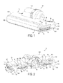
- a cleaner head 10 for a vacuum cleaner comprises a housing 12 and a lower plate, or sole plate 14, comprising a suction opening 16 through which a dirt-bearing fluid flow enters the cleaner head 10.
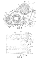
- the housing 12 defines a suction passage 17 (indicated in Figure 7 ) extending from the suction opening 16 to a fluid outlet 18 located at the rear of the housing 12.
- the fluid outlet 18 is dimensioned to connect to a main body or a hose of an upright vacuum cleaner.
- the sole plate 14 is illustrated in more detail in Figures 3 to 5 .
- the sole plate 14 comprises a bottom surface which, in use, faces the floor surface to be cleaned and, as described in more detail below, engages the surface of a carpeted floor surface.
- the bottom surface of the sole plate 14 is generally planar, and comprises two opposing side sections 20, a leading section 22 and a trailing section 24 which extend about the suction opening 16.
- the suction opening 16 is generally rectangular in shape, and is delimited by relatively short side walls 26, a relatively long front wall 28 and a relatively long rear wall 30 which each upstand from the bottom surface of the sole plate 14. These walls also delimit the start of the suction passage 17 through the cleaner head 10.
- the front wall 28 of the suction opening 16 is substantially orthogonal to the bottom surface of the sole plate 14.
- a front working edge 34 of the sole plate 14 is located at the intersection between the leading section 22 of the bottom surface and the front wall 28, and extends substantially uninterruptedly between the side walls 26.
- An inclined front lip 36 extends upwardly and forwardly from the front of the leading section 22, and in use sweeps the fibres of a rug or deeply piled carpeted floor surface beneath the leading section 22 as the cleaner head 10 is manoeuvred over that floor surface, thereby lowering the resistance to motion of the cleaner head 10.
- the rear wall 30 of the suction opening 16 is also inclined forwardly relative to the bottom surface of the sole plate 14 to sweep the fibres of a rug or deeply piled carpeted floor surface beneath the trailing section 24 as the cleaner head 10 is manoeuvred over the floor surface.
- the angle of inclination of the rear wall 30 relative to the bottom surface is substantially the same as the angle of inclination of the front lip 36 relative to the bottom surface, and is preferably in the range from 40 to 50°.
- a rear working edge 38 of the sole plate 14 is located at the intersection between the rear section 24 of the bottom surface and the rear wall 32, and extends substantially uninterruptedly between the side walls 26.
- Two rear lips 40 curve upwardly and rearwardly from the rear of the trailing section 24, and are located on opposite sides of the fluid outlet 18.
- the sole plate 14 is connected to a chassis 50.
- the chassis 50 is substantially rectangular in shape, and comprises relatively short side walls 52, a relatively long front wall 54 and a relatively long rear wall 56.
- the chassis 50 is annular in shape, with these walls delimiting a substantially rectangular aperture for receiving the dirt-bearing fluid flow drawn into the cleaner head 10 through the suction opening 16, and thus also delimit part of the suction passage 17 through the cleaner head 10. This aperture has a size which is similar to that of the suction opening 16.
- the chassis 50 is releasably connected to the housing 12 of the cleaner head 10.
- the chassis 50 comprises an annular projection 58 upstanding from the upper surfaces of the walls 52, 54, 56 of the chassis 50 which locates within an annular groove 60 defined by an L-shaped flange 62 extending about the housing 12 of the cleaner head 10.
- An annular sealing member preferably in the form of a rope seal, may be located within the groove 60 for engaging with the projection 58 to ensure that an air-tight seal is formed between the housing 12 and the chassis 50.
- the front wall 54 of the chassis 50 comprises a plurality of forwardly extending lugs 64.
- the chassis 50 is angled relative to the housing 12 to allow each of these lugs 64 to be located within a respective recess formed in the front of the housing 12.
- the chassis 50 is then pivoted about these lugs 64 and towards the housing 12 to insert the annular projection 58 within the groove 60.
- the chassis 50 also comprises a first pair of annular lugs 66 connected to the rear wall 56 and each arranged to engage with a respective one of a pair of lugs 68 connected to the rear of the housing 12 when the annular projection 58 is fully inserted within the annular groove 60.
- a screw 69 is inserted into each engaging pair of lugs 66, 68 to secure the chassis 50 to the housing 12.
- the sole plate 14 is connected to the chassis 50 by a flexible annular seal, which in this example is in the form of a flexible skirt 70.
- a flexible annular seal which in this example is in the form of a flexible skirt 70.
- One end of the skirt 70 is connected to the upper surfaces of the walls 26, 28, 30 of the sole plate 14 so as to surround the suction opening 16, while the other end of the skirt 70 is connected to the lower surfaces of the walls 52, 54, 56 of the chassis 50 so as to surround the aperture of the chassis 50. Consequently, the skirt 70 also delimits part of the suction passage 17 through the cleaner head 10, and the chassis 50, skirt 70 and sole plate 14 together form a unit which is detachable from the housing 12 of the cleaner head 10.
- the presence of the skirt 70 allows relative movement between the housing 12 and the sole plate 14 during a cleaning operation, as described in more detail below.
- the rear wall 30 of the sole plate 14 has a raised portion 71 to prevent sharp debris entering the housing 12 through the suction opening 16 from damaging or otherwise compromising the integrity of
- the cleaner head 10 is arranged to constrain relative movement between the sole plate 14 and the housing 12 to a direction extending substantially orthogonal to the bottom surface of the sole plate 14.
- the sole plate 14 comprises a pair of rectangular guide members 72 extending upwardly from the front of the sole plate 14.
- Each rectangular guide member 72 passes through an aperture 74 formed in a respective guide retaining member 76 projecting forwardly from the front wall 54 of the chassis 50.
- the rectangular guide members 72 and the guide retaining members 76 are shaped to enable sliding relative movement therebetween in a direction extending substantially orthogonal to the bottom surface of the sole plate 14, and inhibit both relative rotation between the chassis 50 and the sole plate 14 and relative movement between the chassis 50 and the front of the sole plate 14 in the direction of the movement of the cleaner head 10 across the floor surface.
- Each rectangular guide member 72 preferably has a head portion 78 projecting forwardly therefrom and located above its guide retaining member 76.
- the head portion 78 is shaped to engage the upper surface of the guide retaining member 76, and thereby limit the movement of the front of the sole plate 14 away from the housing 12.
- the movement of the front of the sole plate 14 towards the housing 12 may be limited by the abutment of the front lip 36 of the sole plate 14 with the lower surface of the guide retaining members 76.
- other features may be located on the front of the housing 12 for engaging the front lip 36 of the sole plate 14 to limit the movement of the front of the sole plate 14 towards the housing 12.
- the extent of the movement of the front lip 36 of the sole plate 14 relative to the housing 12 is restricted to a distance of around 6.5 to 8 mm.
- the sole plate 14 also comprises a pair of cylindrical guide members 80 extending upwardly from the rear of the sole plate 14.
- Each cylindrical guide member 80 is retained by a respective guide retaining member 82 projecting rearwardly from the rear wall 56 of the chassis 50.
- Each guide retaining member 82 preferably comprises a pair of ribs extending about the cylindrical guide member.
- the cylindrical guide members 80 and the guide retaining members 82 are shaped to enable sliding relative movement therebetween in a direction extending substantially orthogonal to the bottom surface of the sole plate 14.
- Each cylindrical guide member 80 preferably has a head portion 84 projecting forwardly therefrom and located above its guide retaining member 82.
- the head portion 84 is shaped to engage the upper surface of the guide retaining member 82, and thereby limit the movement of the rear of the sole plate 14 away from the housing 12.
- the movement of the rear of the sole plate 14 towards the housing 12 is limited by the abutment of fins 86 extending radially outwardly from each cylindrical guide member 80 with the lower surface of the guide retaining member 82.
- the guide retaining members 82 and the annular lugs 88 are preferably shaped so as to inhibit relative movement between the chassis 50 and the rear of the sole plate 14 in the direction of the movement of the cleaner head 10 across the floor surface.
- the housing 12 comprises a bumper 90 mounted on the front of housing 12 for reducing the risk of impact between the sole plate 14 and objects such as items of furniture or walls during a cleaning operation, which could otherwise cause damage to the guide members 72, 80 and the guide retaining members 76, 82.
- the extent of the movement of the rear lip 40 of the sole plate 14 relative to the housing 12 is restricted to distance of around 5.5 to 6.5 mm, that is, shorter than the extent of the movement of the front lip 36 of the sole plate 14 relative to the housing 12. Consequently, the front of the sole plate 14 is able to pivot slightly about the points of contact between the guide retaining members 82 and the fins 86 once movement of the rear of the sole plate 14 towards the housing 12 has been restricted.
- the skirt 70 is preferably in the form of a bellows-type element to facilitate repeated compression and extension of the skirt 70 due to relative movement between the sole plate 14 and the housing 12 during a cleaning operation.
- the skirt 70 is preferably formed from a resilient material, which preferably comprises latex.
- the cleaner head 10 comprises an agitator for agitating dirt and dust located on the floor surface.
- the agitator comprises a rotatable brush bar assembly 100 which is mounted within a brush bar chamber 102 of the housing 12.
- the chassis 50 and the skirt 70 extend about the brush bar assembly 100. The removal of the chassis 50 from the housing 12 enables a user to access the brush bar assembly 100, for example for cleaning and/or removal from the brush bar chamber 102.
- the brush bar assembly 100 is driven by a motor 104 located in a motor housing 106 of the housing 12.
- the brush bar assembly 100 is connected to the motor 104 by a drive mechanism 107, described in more detail below, located within a drive mechanism housing 108 so that the drive mechanism 107 is isolated from the air passing through the suction passage 17.
- a drive mechanism 107 located within a drive mechanism housing 108 so that the drive mechanism 107 is isolated from the air passing through the suction passage 17.
- the motor housing 106 is located centrally above, and rearward of, the brush bar chamber 102. Consequently, the drive mechanism 107 extends into the brush bar chamber 102 between the side walls 110, 112 of the brush bar chamber 102, closer to side wall 110 than to side wall 112.
- the brush bar assembly 100 comprises a first, relatively long brush bar 114 located between the drive mechanism housing 108 and side wall 110 of the brush bar chamber 102, and a second, relatively short brush bar 116, co-axial with the first brush bar 114 and located between the drive mechanism housing 108 and side wall 112 of the brush bar chamber 102.
- Each brush bar 114, 116 has one end connected to the drive mechanism 107 to enable the brush bars 114, 116 to be driven by the motor 104.
- the other ends of the brush bars 114, 116 are rotatably supported by end caps 118 mounted on the side walls 110, 112 of brush bar chamber 102.
- Each brush bar 114, 116 comprises a first set of relatively long, stiff bristles 120 and a second set of relatively short, soft bristles 122.
- Each set of bristles 120, 122 comprises a plurality of clusters arranged in a helical formation at regular intervals along the brush bar 114, 116, with the helical pattern of the clusters of the second set of bristles 122 being angularly spaced from the helical pattern of the clusters of the first set of bristles 120.
- the brush bar chamber 102 provides part of the suction passage 17 extending from the suction opening 16 to the fluid outlet 18 located at the rear of the housing 12. Consequently, the brush bar chamber 102 comprises a chamber air outlet 130 through which the air flow leaves the brush bar chamber 102, and enters a conduit 132 extending beneath the motor housing 106 for conveying the air flow to the fluid outlet 18.
- the first brush bar 114 is located within a first section 102a of the brush bar chamber 102 and the second brush bar 116 is located within a second section 102b of the brush bar chamber 102.
- the air outlet 130 is in the form of an elongate aperture which extends between, and into, both sections 102a, 102b of the brush bar chamber 102.
- the air outlet 130 from the brush bar chamber 102 is preferably in the form of a slot, which preferably has an aspect ratio of at least 3:1, more preferably of at least 5:1.
- the fluid outlet 108 is in the form of a substantially circular aperture, and so the conduit 132 is shaped so that its cross-section changes gradually and smoothly from an elongate shape to a circular shape.
- the fluid outlet 18 of the cleaner head 10 is connected to a main body of a cleaning appliance (not shown), which contains dirt and dust separating apparatus and a motor-driven fan unit for drawing dirt-bearing air through the suction opening 16 from the floor surface.
- a cleaning appliance not shown
- dirt and dust separating apparatus and a motor-driven fan unit for drawing dirt-bearing air through the suction opening 16 from the floor surface.
- the dirt-bearing air passes through the suction passage 17 and into the main body of the cleaning appliance, wherein dirt and dust is separated from the air before it is expelled to the atmosphere.
- the cleaner head 10 comprises a plurality of floor engaging support members for restricting the movement of the housing 12 towards the sole plate 14.
- this plurality of floor engaging support members comprises a pair of rear support members 140.
- Each of the rear support members 140 is connected to the end of an arm 142 rigidly connected to and extending rearwardly from a respective side wall 110, 112 of the brush bar chamber 102 so that each of the rear support members 140 is located behind the sole plate 14.
- the plurality of floor engaging support members also comprises a further support member 143 located in front of the rear support members 140 to prevent the cleaner head 10 from pivoting about these rear support members 140 and "digging" into the floor surface during use.
- the further support member 143 is mounted on the drive mechanism housing 108 so as to protrude through the suction opening 16 of the cleaner head 10.
- Each support member 140, 143 comprises a support having a substantially cylindrical upper portion 144, and a curved, preferably substantially hemispherical, lower portion 146.
- Each support member 140, 143 also comprises a floor engaging rolling element 148 mounted within a recess formed in the outer surface of the lower portion 146 so as to protrude from the support.
- the rolling element 148 is preferably in the form of a cylindrical rolling element which rolls along the floor surface as the cleaner head 10 is manoeuvred over the floor surface during a cleaning operation to minimise the resistance to the movement of the support members 140, 143, particularly over a hard floor surface.
- the rolling element 148 is preferably arranged so that the point of contact between the rolling element 148 and the floor surface is substantially coincident with a locus 149 described by the lower surface of the support member 140, 143.
- the outer surface of the rolling element 148 is preferably substantially coincident with the lowest point of a virtual hemispherical shape which is concentric with, and has the same radius of curvature as, the lower portion 146 of the support.
- the force acting on the housing 12 pushes the support members 140, 143 into the fibres of the carpet so that the hemispherical surfaces of the lower portions 146 of the support members 140, 143 engage the carpeted floor surface 170.
- the hemispherical shape of the lower portions 146 of the support members 140, 143 provides a substantially constant resistance to movement of the cleaner head 10 across the carpeted floor surface 170 in any direction, and minimises the resistance to movement of the cleaner head 10 across the carpeted floor surface.
- the rolling elements 148 do not protrude beyond the locus described with the curved shape of the lower portions 146 of the support members 140, 143, the rolling elements 148 provide minimal resistance to the movement of the cleaner head 10 over the floor surface 170.
- the bottom surface of the sole plate 14 comes into contact with the carpeted floor surface 170. Due to the compression of the flexible skirt 70 located between the housing 12 and the sole plate 14, further sinking of the support members 140, 143 into the carpet causes the guide retaining members 76, 82, which are connected to the housing 12 by the chassis 50, to move downwardly away from the head portions 78, 84 of the guide members 72, 80 connected to the sole plate 14. Consequently, the housing 12 moves relative to the sole plate 14, which remains located on the upper surface of the carpeted floor surface 170.
- some of the fibres of the carpet may protrude through the suction opening 16 as the sole plate 14 sinks slightly into the carpet under its own weight.
- the dirt and dust within these fibres can be agitated by the rotating brush bar assembly 100 located within the housing 12 and become entrained within the air flow drawn into the suction passage 17.
- the lower portions 146 of the support members 140, 143 preferably have a radius in the range from 10 to 20 mm so as to not sink so far into the fibres of the carpet that the housing 12 starts to exert a significant force on the sole plate 14 once the fins 86 abut with the lower surface of the guide retaining member 82.
- the flexible skirt 70 preferably has an elasticity selected so that an amount of the force acting on the housing 12 of the cleaner head 10 is transferred to the sole plate 14 by the compression of the flexible skirt 70.
- the amount of this force is preferably less than 10 N, and in the preferred embodiment is between 2 and 7 N. This pushes the sole plate 14 into the carpeted floor surface, resulting in the protrusion of carpet fibres through the suction opening 16 for agitation by the brush bar assembly 100.
- the drive mechanism 107 for connecting the brush bar assembly 100 to the motor 104 comprises a rotatable input drive member 180, preferably in the form of a pulley, mounted on the drive shaft 182 of the motor 104 for rotation about the longitudinal axis of the drive shaft 182.
- the drive mechanism 107 further comprises a rotatable output drive member 184, also preferably in the form of a pulley, connected to the input drive member 180 by a drive belt 186.
- the axis of rotation of the output drive member 184 is substantially parallel to the axis of rotation of the input drive member 180.
- the output drive member 184 is rotatably supported within the drive mechanism housing 108 by a rolling bearing 188.
- a first drive dog 190 is mounted on one side of the output drive member 184 for connection to the first brush bar 114, and a second drive dog 192 is mounted on the opposite side of the output drive member for connection to the second brush bar 116.
- the drive mechanism housing 108 is moveable relative to the motor 104 in a direction substantially orthogonal to the axes of rotation of the drive members 180, 184, and so the output drive member 184 is similarly moveable relative to the input drive member 180.
- Guide members may be provided for restricting the movement of the housing 108 relative to the motor 104 to this direction.
- a belt tensioning member 194 is located between the drive members 180, 184 for tensioning the belt 186 by urging the output drive member 184 away from input drive member 180.
- the belt tensioning member 194 is annular, and is mounted on a spigot 196 connected to the drive mechanism housing 108 and located between the rotational axes of the drive members 180, 184.
- the spigot 196 extends substantially parallel to the rotational axes of the drive members 180, 184.
- the belt tensioning member 194 is moveable along the spigot 196.
- Part of the annular outer surface of the belt tensioning member 194 is shaped to define a wedge-shaped portion 198 which is inclined to the longitudinal axis of the spigot 196.
- the wedge-shaped portion 198 of the belt tensioning member 194 is urged against a conformingly wedge-shaped portion 200 of a mounting plate 202 connected to the motor 104 by a resilient member 204 located between the belt tensioning member 194 and a cover 206 of the drive mechanism housing 108. This causes the resilient member 204 to be urged away from the input drive member 180 by the wedge-shaped portion 200 of the mounting plate 202. As the belt tensioning member 194 extends about part of the drive mechanism housing 108, namely the spigot 196, this results in the drive mechanism housing 108, and the output drive member 184 supported thereby, being urged away from the input drive member 180 to maintain the belt 186 in a fully tensioned state.
Landscapes
- Engineering & Computer Science (AREA)
- Mechanical Engineering (AREA)
- Nozzles For Electric Vacuum Cleaners (AREA)
Abstract
Description
- The present invention relates to a cleaner head for a cleaning appliance. In its preferred embodiment, the present invention relates to a cleaner head for a vacuum cleaning appliance.
- An upright vacuum cleaner typically comprises a main body containing dirt and dust separating apparatus, a cleaner head mounted on the main body and having a suction opening, and a motor-driven fan unit for drawing dirt-bearing air through the suction opening. The dirt-bearing air is conveyed to the separating apparatus so that dirt and dust can be separated from the air before the air is expelled to the atmosphere.
- The suction opening is directed downwardly to face the floor surface to be cleaned. The separating apparatus can take the form of a filter, a filter bag or, as is known, a cyclonic arrangement. The present invention is not concerned with the nature of the separating apparatus and is therefore applicable to vacuum cleaners utilizing any of the above arrangements or another suitable separating apparatus.
- A driven agitator, usually in the form of a brush bar, is supported in the cleaner head so as to protrude to a small extent from the suction opening. The brush bar is activated mainly when the vacuum cleaner is used to clean carpeted surfaces. The brush bar comprises an elongate cylindrical core bearing bristles which extend radially outward from the core. The brush bar may be driven by an air turbine or by an electric motor powered by a power supply derived from the main body of the cleaner. The brush bar may be driven by the motor via a drive belt, or may be driven directly by the motor, so as to rotate within the suction opening. Rotation of the brush bar causes the bristles to sweep along the surface of the carpet to be cleaned to loosen dirt and dust, and pick up debris. The suction of air causes air to flow underneath the sole plate and around the brush bar to help lift the dirt and dust from the surface of the carpet and then carry it from the suction opening through the cleaner head towards the separating apparatus. Vacuum cleaner manufacturers often provide potential customers with a measure of the "airwatts" developed by their products. This is a measure of the amount of suction provided at the suction opening. The suction of air through the suction opening creates a pressure difference between the air passing through the cleaner head and the external environment, which generates a force acting downwardly on the cleaner head towards the surface to be cleaned. Consequently, a disadvantage of providing a high measure of airwatts at the suction opening is that the sole plate can be sucked onto the surface to be cleaned. This can reduce the amount of air which can enter the suction opening from outside the vacuum cleaner, resulting in a reduction of the efficiency of the cleaner. In addition, the cleaner head can become difficult to manoeuvre across the surface to be cleaned, in particular over carpeted surfaces.
- It is known to provide one or more air channels located on the side of the cleaner head to allow additional air to be bled into the vacuum cleaner from the external environment. Providing this additional airflow into the vacuum cleaner can reduce the force with which the cleaner head is pushed on to the surface, and thereby reduce the force required to manoeuvre the cleaner head over the surface to be cleaned. However, a disadvantage of providing this additional air flow into the vacuum cleaner is that the amount of suction developed at the suction opening is reduced, which in turn reduces the pick up performance of the vacuum cleaner.
- In a first aspect the present invention provides a cleaner head for a cleaning appliance, comprising a housing, a moveable agitator located within the housing, and a detachable unit extending about the agitator, the detachable unit comprising a sole plate having a suction opening through which dirt-bearing air enters the cleaner head, a chassis detachably connected to the housing, and a flexible annular seal for allowing relative movement between the housing and the sole plate, wherein one end of the flexible annular seal is connected to the chassis and the other end of the flexible annular seal is connected to the sole plate.
- When an air flow is generated through the suction opening, the pressure difference between the air passing through the cleaner head and the external environment causes the housing of the cleaner head to be sucked down towards the floor surface, whereas the fibres of a carpeted surface are lifted towards the housing of the cleaner head. Due to the presence of the flexible annular seal, which may be in the form of a flexible skirt or membrane, between the housing and the sole plate, the housing is capable of moving relative to the sole plate. Consequently, only a relatively small amount of force, if any, is applied to the sole plate by the housing, thereby preventing the sole plate from being pushed into the pile of the carpet by the housing. In turn, this means that the sole plate does not cause significant resistance to the movement of the cleaner head over the floor surface, and does not unduly restrict the flow of air into the cleaner head.
- The flexible annular seal is connected at one end thereof to the sole plate so as to surround the suction opening. The other end of the flexible annular seal is preferably connected to a chassis which is detachably connected to the housing. This can enable the sole plate, flexible annular seal and the chassis to be removed as a single detachable unit from the cleaner head, for example to provide access to an agitator located within the housing, without compromising the integrity of the seal between the chassis and the sole plate.
- The flexible annular seal may thus define part of a suction passage for conducting the dirt-bearing air from the suction opening to an air outlet. Thus, in comparison to a cleaner head using air channels to restrict the force acting on the cleaner head by allowing air to enter the suction passage from the external environment, the use of a flexible annular seal can enable an improved air flow into the cleaner head from around the periphery thereof and through a carpeted flow surface therebeneath to be achieved for a given air pressure within the housing of the cleaner head, thereby improving pick up performance.
- The majority of the air flow entering the suction opening of the sole plate will pass beneath the edges of the sole plate and, when the sole plate is located on a carpeted surface, through the carpet pile. As the sole plate is not being urged against the floor surface by the housing of the cleaner head, the air flow passing beneath the edges of the sole plate can tend to lift the sole plate away from the floor surface, particularly when the amount of suction provided at the suction opening is relatively high. This could have the effect of increasing the pressure within the cleaner head, and in turn reducing the speed of the air flow through the suction opening and compromising the pick up performance of the cleaner head.
- To inhibit lifting of the sole plate from the floor surface during use, the sole plate may be provided with sufficient mass as to resist movement away from the floor surface under the action of the air flow passing beneath the sole plate. Alternatively, the flexible annular seal may be formed from resilient material having an elasticity selected so that an amount of the force acting on the cleaner head is transferred to the sole plate through compression of the flexible annular seal. In the preferred embodiment the flexible annular seal is formed from a material comprising latex. Additionally, or as another alternative, one or more springs or other resilient members may be provided between the housing and the sole plate for applying a force to the sole plate. In the preferred embodiment the flexible annular seal comprises a bellows seal element to facilitate the compression and expansion of the skirt as the cleaner head is moved, for example between a hard floor surface and a carpeted surface.
- The downwards force acting on the sole plate, either under its own weight or in combination with the force applied through the flexible annular seal and/or other resilient members(s), is preferably sufficient to minimise the risk of the sole plate lifting from the floor surface during use while minimising the resistance to the manoeuvring of the cleaner head over the floor surface. This force is preferably less than 10 N, and in the preferred embodiment is between 2 and 7 N.
- The cleaner head preferably comprises features which limit the extent of the relative movement between the sole plate and the housing to avoid over-compression of the flexible member. The relative movement between the sole plate and the housing is preferably restricted to less than 20 mm, more preferably less than 15 mm.
- In order to assist movement of the cleaner head over a deep pile carpeted floor, in the preferred embodiment the leading edge of the sole plate is moveable relative to the housing by a greater amount than the trailing edge of the sole plate. This allows the leading edge to move relative to the housing when the movement of the trailing edge of the sole plate relative to the housing is inhibited. In the preferred embodiment the extent of the movement of the rear of the sole plate relative to the housing is restricted to a distance of around 5.5 to 6.5 mm, whereas the extent of the movement of the front of the sole plate relative to the housing is restricted to a distance of around 6.5 to 8 mm.
- The sole plate comprises a bottom surface which, in use, faces the floor surface to be cleaned, and which has a leading section and a trailing section located on opposite sides of the suction opening. The sole plate also comprises a front wall and a rear wall which each upstand from the bottom surface of the sole plate and define, in part, the suction opening. The rear wall is preferably inclined forwardly relative to the bottom surface to guide fibres of a carpeted floor surface beneath the trailing section of the bottom surface of the sole plate as the cleaner head is manoeuvred over the floor surface.
- The chassis is preferably annular in shape, and defines part of a suction passage extending through the housing. The housing preferably comprises an annular sealing element for providing an air-tight seal between the chassis and the housing.
- The cleaner head preferably comprises guide means for guiding movement of the housing relative to the sole plate. The guide means preferably comprises a plurality of guide members, which may in the form of rods, bars, pins or other elongate members, connected to one of the sole plate and the chassis or housing. In this case, the other of the sole plate and the chassis or housing may comprise a plurality of guide retaining members each for receiving a respective guide member and within which the guide members move with movement of the housing towards or away from the sole plate. In the preferred embodiment the sole plate comprises a plurality of guide members which are received within guide members connected to, or integral with, the chassis.
- The guide means preferably also serve to inhibit relative movement between the sole plate and the housing in the direction of movement of the cleaner head across the floor surface. Alternatively, separate means may be provided for inhibiting relative movement between the sole plate and the housing in the direction of movement of the cleaner head across the floor surface. The guide means may preferably comprise means for limiting the extent of the movement of the sole plate away from the chassis, and/or means for limiting the extent of the movement of the sole plate towards the chassis.
- The agitator preferably comprises a rotatable brush bar assembly. The flexible annular seal preferably surrounds the brush bar assembly. The brush bar assembly is preferably driven by a motor located in a motor housing. The brush bar assembly is connected to the motor by a drive mechanism, which may comprise gears or a belt, located within a drive mechanism housing so that the drive mechanism is isolated from the air passing through the suction passage. The brush bar assembly is preferably located within a brush bar chamber of the housing, which chamber forms part of the suction passage extending from the suction opening to the air outlet. The brush bar chamber preferably comprises an air outlet from which the air flow leaves the brush bar chamber. To provide a balanced cleaner head in which the weight of the motor is spread evenly about the lower surface of the sole plate, the motor is preferably located centrally within the cleaner head. Consequently, the drive mechanism may extend into the brush bar chamber, between the side walls of the chamber and closer to one side wall than the other. In this case, the brush bar assembly may comprise a first, relatively long brush bar located between the drive mechanism housing and a first side wall of the chamber, and a second, relatively short brush bar, co-axial with the first brush bar and located between the drive mechanism housing and a second side wall of the chamber.
- The first brush bar is located within a first section of the brush bar chamber and the second brush bar is located within a second section of the brush bar chamber. To minimise the pressure difference between these two sections of the brush bar chamber, and to enable the dirt and dust agitated from the floor surface by both brush bars to be conveyed rapidly to the air outlet of the cleaner head, the air flow is preferably drawn through both of the brush bar chamber sections. In view of this, the air outlet from the brush bar chamber preferably extends between, and into, both sections of the brush bar chamber. The air outlet from the brush bar chamber is preferably in the form of a slot, which preferably has an aspect ratio of at least 3:1, more preferably of at least 5:1.
- Each brush bar preferably comprises a first set of bristles and a second set of bristles which are different from the first set of bristles. Each set of bristles preferably comprises a plurality of clusters arranged in a helical formation at regular intervals along the brush bar, with the helical pattern of the clusters of the second set of bristles being angularly spaced from the helical pattern of the clusters of the first set of bristles. The first set of bristles preferably comprises relatively long, stiff bristles for plush pick up, whereas the second set of bristles preferably comprises relatively short, soft bristles for fibre pick up.
- Where the drive mechanism comprises a belt connecting the motor to the brush bar assembly, wear of the belt during use of the cleaner head can cause the belt to expand. In turn, this can cause the belt to slip, which can result in damage to the motor and/or other components of the drive mechanism. In view of this, the drive mechanism connecting the motor to the brush bar assembly preferably comprises a rotatable input drive member connected to the motor, a rotatable output drive member connected to the brush bar assembly and moveable relative to the input drive member in a direction orthogonal to the axes of rotation of the drive members, a belt connecting the input drive member to the output drive member, and a belt tensioning member located between the drive members for tensioning the belt by urging the output drive member away from input drive member. This can maintain the tension of the belt at a substantially constant level during the life of the belt.
- The output drive member is preferably moveable relative to the input drive member in a direction extending between the axes of rotation of the drive members. The belt tensioning member is preferably also moveable relative to the drive members in this direction.
- Preferably, the output drive member is rotatably supported by a housing for the drive mechanism, with the belt tensioning member being arranged to move the housing relative to the input drive member. The belt tensioning member is preferably mounted on a spigot connected to the housing, which spigot is preferably substantially parallel to the axes of rotation of the drive members. The belt tensioning member is preferably moveable along the spigot, and is thus moveable in a direction substantially perpendicular to the direction of the relative movement between the axes of rotation of the drive members.
- The belt tensioning member is preferably urged away from the input drive member by an abutment member connected to the motor. Engaging portions of the abutment member and the belt tensioning member are preferably wedge-shaped. A resilient member or other means is preferably provided for urging the belt tensioning member against the abutment member. This resilient element may be conveniently located between the belt tensioning member and the housing.
- In a second aspect the present invention provides a cleaning appliance, preferably a vacuum cleaner, comprising a cleaner head as aforementioned.
- An embodiment of the present invention will now be described, by way of example only, with reference to the accompanying drawings, in which:
-
Figure 1 is a front perspective view of a cleaner head; -
Figure 2 is a rear perspective view of the cleaner head ofFigure 1 ; -
Figure 3 is an underside view of the cleaner head ofFigure 1 ; -
Figure 4 is a front perspective view of the chassis and sole plate of the cleaner head ofFigure 1 ; -
Figure 5 is a rear perspective view of the chassis and sole plate ofFigure 4 ; -
Figure 6 is an oblique underside view of the cleaner head ofFigure 1 , with the brush bars removed; -
Figure 7 is a cross-sectional view taken along line X-X inFigure 3 ; -
Figure 8 is part of a cross-sectional view taken along line Y-Y inFigure 3 ; -
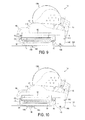
Figure 9 is a side view of the cleaner head ofFigure 1 when located on a hard floor surface; -
Figure 10 is a side view of the cleaner head ofFigure 1 when located on a carpeted surface; -
Figure 11 is a cross-sectional view taken along line Z-Z inFigure 7 of the drive mechanism for the brush bar assembly; and -
Figure 12 is a perspective view of the drive mechanism ofFigure 11 , with the cover of the drive mechanism removed. - With reference first to
Figures 1 and 2 , acleaner head 10 for a vacuum cleaner comprises ahousing 12 and a lower plate, orsole plate 14, comprising asuction opening 16 through which a dirt-bearing fluid flow enters thecleaner head 10. Thehousing 12 defines a suction passage 17 (indicated inFigure 7 ) extending from thesuction opening 16 to afluid outlet 18 located at the rear of thehousing 12. Thefluid outlet 18 is dimensioned to connect to a main body or a hose of an upright vacuum cleaner. - The
sole plate 14 is illustrated in more detail inFigures 3 to 5 . Thesole plate 14 comprises a bottom surface which, in use, faces the floor surface to be cleaned and, as described in more detail below, engages the surface of a carpeted floor surface. The bottom surface of thesole plate 14 is generally planar, and comprises two opposingside sections 20, a leadingsection 22 and a trailingsection 24 which extend about thesuction opening 16. - The
suction opening 16 is generally rectangular in shape, and is delimited by relativelyshort side walls 26, a relatively longfront wall 28 and a relatively longrear wall 30 which each upstand from the bottom surface of thesole plate 14. These walls also delimit the start of thesuction passage 17 through thecleaner head 10. A plurality of rug strips 32 for guiding the movement of thecleaner head 10 over a rug or deeply piled carpeted floor surface, extend across the suction opening 16 from thefront wall 28 to therear wall 30, and are substantially parallel with theside walls 26. - The
front wall 28 of thesuction opening 16 is substantially orthogonal to the bottom surface of thesole plate 14. A front workingedge 34 of thesole plate 14 is located at the intersection between the leadingsection 22 of the bottom surface and thefront wall 28, and extends substantially uninterruptedly between theside walls 26. An inclinedfront lip 36 extends upwardly and forwardly from the front of the leadingsection 22, and in use sweeps the fibres of a rug or deeply piled carpeted floor surface beneath the leadingsection 22 as thecleaner head 10 is manoeuvred over that floor surface, thereby lowering the resistance to motion of thecleaner head 10. - The
rear wall 30 of thesuction opening 16 is also inclined forwardly relative to the bottom surface of thesole plate 14 to sweep the fibres of a rug or deeply piled carpeted floor surface beneath the trailingsection 24 as thecleaner head 10 is manoeuvred over the floor surface. The angle of inclination of therear wall 30 relative to the bottom surface is substantially the same as the angle of inclination of thefront lip 36 relative to the bottom surface, and is preferably in the range from 40 to 50°. Arear working edge 38 of thesole plate 14 is located at the intersection between therear section 24 of the bottom surface and therear wall 32, and extends substantially uninterruptedly between theside walls 26. Tworear lips 40 curve upwardly and rearwardly from the rear of the trailingsection 24, and are located on opposite sides of thefluid outlet 18. - The
sole plate 14 is connected to achassis 50. Thechassis 50 is substantially rectangular in shape, and comprises relativelyshort side walls 52, a relatively longfront wall 54 and a relatively longrear wall 56. Thechassis 50 is annular in shape, with these walls delimiting a substantially rectangular aperture for receiving the dirt-bearing fluid flow drawn into thecleaner head 10 through thesuction opening 16, and thus also delimit part of thesuction passage 17 through thecleaner head 10. This aperture has a size which is similar to that of thesuction opening 16. - The
chassis 50 is releasably connected to thehousing 12 of thecleaner head 10. With reference also toFigure 8 , thechassis 50 comprises anannular projection 58 upstanding from the upper surfaces of thewalls chassis 50 which locates within anannular groove 60 defined by an L-shapedflange 62 extending about thehousing 12 of thecleaner head 10. An annular sealing member, preferably in the form of a rope seal, may be located within thegroove 60 for engaging with theprojection 58 to ensure that an air-tight seal is formed between thehousing 12 and thechassis 50. Thefront wall 54 of thechassis 50 comprises a plurality of forwardly extendinglugs 64. To attach thechassis 50 to thehousing 12, thechassis 50 is angled relative to thehousing 12 to allow each of theselugs 64 to be located within a respective recess formed in the front of thehousing 12. Thechassis 50 is then pivoted about theselugs 64 and towards thehousing 12 to insert theannular projection 58 within thegroove 60. Thechassis 50 also comprises a first pair ofannular lugs 66 connected to therear wall 56 and each arranged to engage with a respective one of a pair oflugs 68 connected to the rear of thehousing 12 when theannular projection 58 is fully inserted within theannular groove 60. Ascrew 69 is inserted into each engaging pair oflugs chassis 50 to thehousing 12. - The
sole plate 14 is connected to thechassis 50 by a flexible annular seal, which in this example is in the form of aflexible skirt 70. One end of theskirt 70 is connected to the upper surfaces of thewalls sole plate 14 so as to surround thesuction opening 16, while the other end of theskirt 70 is connected to the lower surfaces of thewalls chassis 50 so as to surround the aperture of thechassis 50. Consequently, theskirt 70 also delimits part of thesuction passage 17 through thecleaner head 10, and thechassis 50,skirt 70 andsole plate 14 together form a unit which is detachable from thehousing 12 of thecleaner head 10. The presence of theskirt 70 allows relative movement between thehousing 12 and thesole plate 14 during a cleaning operation, as described in more detail below. With reference toFigure 7 , therear wall 30 of thesole plate 14 has a raised portion 71 to prevent sharp debris entering thehousing 12 through the suction opening 16 from damaging or otherwise compromising the integrity of the seal between thesole plate 14 and theskirt 70. - The
cleaner head 10 is arranged to constrain relative movement between thesole plate 14 and thehousing 12 to a direction extending substantially orthogonal to the bottom surface of thesole plate 14. With reference toFigures 4 and5 , thesole plate 14 comprises a pair ofrectangular guide members 72 extending upwardly from the front of thesole plate 14. Eachrectangular guide member 72 passes through anaperture 74 formed in a respectiveguide retaining member 76 projecting forwardly from thefront wall 54 of thechassis 50. Therectangular guide members 72 and theguide retaining members 76 are shaped to enable sliding relative movement therebetween in a direction extending substantially orthogonal to the bottom surface of thesole plate 14, and inhibit both relative rotation between thechassis 50 and thesole plate 14 and relative movement between thechassis 50 and the front of thesole plate 14 in the direction of the movement of thecleaner head 10 across the floor surface. - Each
rectangular guide member 72 preferably has ahead portion 78 projecting forwardly therefrom and located above itsguide retaining member 76. Thehead portion 78 is shaped to engage the upper surface of theguide retaining member 76, and thereby limit the movement of the front of thesole plate 14 away from thehousing 12. The movement of the front of thesole plate 14 towards thehousing 12 may be limited by the abutment of thefront lip 36 of thesole plate 14 with the lower surface of theguide retaining members 76. Alternatively, other features may be located on the front of thehousing 12 for engaging thefront lip 36 of thesole plate 14 to limit the movement of the front of thesole plate 14 towards thehousing 12. In this example, the extent of the movement of thefront lip 36 of thesole plate 14 relative to thehousing 12 is restricted to a distance of around 6.5 to 8 mm. - The
sole plate 14 also comprises a pair ofcylindrical guide members 80 extending upwardly from the rear of thesole plate 14. Eachcylindrical guide member 80 is retained by a respectiveguide retaining member 82 projecting rearwardly from therear wall 56 of thechassis 50. Eachguide retaining member 82 preferably comprises a pair of ribs extending about the cylindrical guide member. Again, thecylindrical guide members 80 and theguide retaining members 82 are shaped to enable sliding relative movement therebetween in a direction extending substantially orthogonal to the bottom surface of thesole plate 14. Eachcylindrical guide member 80 preferably has ahead portion 84 projecting forwardly therefrom and located above itsguide retaining member 82. Thehead portion 84 is shaped to engage the upper surface of theguide retaining member 82, and thereby limit the movement of the rear of thesole plate 14 away from thehousing 12. The movement of the rear of thesole plate 14 towards thehousing 12 is limited by the abutment offins 86 extending radially outwardly from eachcylindrical guide member 80 with the lower surface of theguide retaining member 82. When thechassis 50 is connected to thehousing 12, thehead portions 84 of thecylindrical guide members 80 are each received within a respective one of a second pair ofannular lugs 88 located on the rear of thehousing 12, inwardly from the first pair ofannular lugs 68, and within which thehead portions 84 of thecylindrical guide members 80 are slidably moveable. Theguide retaining members 82 and theannular lugs 88 are preferably shaped so as to inhibit relative movement between thechassis 50 and the rear of thesole plate 14 in the direction of the movement of thecleaner head 10 across the floor surface. Thehousing 12 comprises abumper 90 mounted on the front ofhousing 12 for reducing the risk of impact between thesole plate 14 and objects such as items of furniture or walls during a cleaning operation, which could otherwise cause damage to theguide members guide retaining members - In this example, the extent of the movement of the
rear lip 40 of thesole plate 14 relative to thehousing 12 is restricted to distance of around 5.5 to 6.5 mm, that is, shorter than the extent of the movement of thefront lip 36 of thesole plate 14 relative to thehousing 12. Consequently, the front of thesole plate 14 is able to pivot slightly about the points of contact between theguide retaining members 82 and thefins 86 once movement of the rear of thesole plate 14 towards thehousing 12 has been restricted. - The
skirt 70 is preferably in the form of a bellows-type element to facilitate repeated compression and extension of theskirt 70 due to relative movement between thesole plate 14 and thehousing 12 during a cleaning operation. Theskirt 70 is preferably formed from a resilient material, which preferably comprises latex. - With reference now to
Figures 3 and7 , thecleaner head 10 comprises an agitator for agitating dirt and dust located on the floor surface. In this example the agitator comprises a rotatablebrush bar assembly 100 which is mounted within abrush bar chamber 102 of thehousing 12. Thechassis 50 and theskirt 70 extend about thebrush bar assembly 100. The removal of thechassis 50 from thehousing 12 enables a user to access thebrush bar assembly 100, for example for cleaning and/or removal from thebrush bar chamber 102. - The
brush bar assembly 100 is driven by amotor 104 located in amotor housing 106 of thehousing 12. Thebrush bar assembly 100 is connected to themotor 104 by adrive mechanism 107, described in more detail below, located within adrive mechanism housing 108 so that thedrive mechanism 107 is isolated from the air passing through thesuction passage 17. To provide a balancedcleaner head 10 in which the weight of themotor 104 is spread evenly about the bottom surface of thesole plate 14, themotor housing 106 is located centrally above, and rearward of, thebrush bar chamber 102. Consequently, thedrive mechanism 107 extends into thebrush bar chamber 102 between theside walls brush bar chamber 102, closer toside wall 110 than toside wall 112. - In view of this, the
brush bar assembly 100 comprises a first, relativelylong brush bar 114 located between thedrive mechanism housing 108 andside wall 110 of thebrush bar chamber 102, and a second, relativelyshort brush bar 116, co-axial with thefirst brush bar 114 and located between thedrive mechanism housing 108 andside wall 112 of thebrush bar chamber 102. Eachbrush bar drive mechanism 107 to enable the brush bars 114, 116 to be driven by themotor 104. The other ends of the brush bars 114, 116 are rotatably supported byend caps 118 mounted on theside walls brush bar chamber 102. Eachbrush bar stiff bristles 120 and a second set of relatively short,soft bristles 122. Each set ofbristles brush bar bristles 122 being angularly spaced from the helical pattern of the clusters of the first set ofbristles 120. - The
brush bar chamber 102 provides part of thesuction passage 17 extending from thesuction opening 16 to thefluid outlet 18 located at the rear of thehousing 12. Consequently, thebrush bar chamber 102 comprises achamber air outlet 130 through which the air flow leaves thebrush bar chamber 102, and enters aconduit 132 extending beneath themotor housing 106 for conveying the air flow to thefluid outlet 18. With reference toFigure 6 , in which the brush bars 114, 116 have been omitted for clarity, thefirst brush bar 114 is located within a first section 102a of thebrush bar chamber 102 and thesecond brush bar 116 is located within asecond section 102b of thebrush bar chamber 102. To enable the air flow to pass rapidly from eachsection 102a, 102b of thebrush bar chamber 102 into theconduit 132, theair outlet 130 is in the form of an elongate aperture which extends between, and into, bothsections 102a, 102b of thebrush bar chamber 102. Theair outlet 130 from thebrush bar chamber 102 is preferably in the form of a slot, which preferably has an aspect ratio of at least 3:1, more preferably of at least 5:1. In contrast, thefluid outlet 108 is in the form of a substantially circular aperture, and so theconduit 132 is shaped so that its cross-section changes gradually and smoothly from an elongate shape to a circular shape. - The
fluid outlet 18 of thecleaner head 10 is connected to a main body of a cleaning appliance (not shown), which contains dirt and dust separating apparatus and a motor-driven fan unit for drawing dirt-bearing air through the suction opening 16 from the floor surface. In use, the dirt-bearing air passes through thesuction passage 17 and into the main body of the cleaning appliance, wherein dirt and dust is separated from the air before it is expelled to the atmosphere. - When an air flow is generated through the
suction passage 17, a pressure difference is generated between the air passing through thecleaner head 10 and the external environment. This pressure difference generates a force which acts downwardly on thehousing 12 of thecleaner head 10 towards the floor surface. Due to the presence of theflexible skirt 70 between thehousing 12 and thesole plate 14, thehousing 12 moves relative to thesole plate 14. Consequently, only a relatively small amount of force, if any, is applied to thesole plate 14 by thehousing 12, preventing thesole plate 14 from being urged against the floor surface by thehousing 12. As a result, the flow of air into the suction opening 16 from beneath the bottom surface of thesole plate 14 is not unduly restricted, and thesole plate 14 does not cause significant resistance to the movement of thecleaner head 10 over the floor surface. - To prevent the
housing 12 from being forced against thesole plate 14 through extensive compression of theskirt 70, thecleaner head 10 comprises a plurality of floor engaging support members for restricting the movement of thehousing 12 towards thesole plate 14. Returning toFigures 2 and3 , this plurality of floor engaging support members comprises a pair ofrear support members 140. Each of therear support members 140 is connected to the end of anarm 142 rigidly connected to and extending rearwardly from arespective side wall brush bar chamber 102 so that each of therear support members 140 is located behind thesole plate 14. The plurality of floor engaging support members also comprises afurther support member 143 located in front of therear support members 140 to prevent thecleaner head 10 from pivoting about theserear support members 140 and "digging" into the floor surface during use. In this example, thefurther support member 143 is mounted on thedrive mechanism housing 108 so as to protrude through thesuction opening 16 of thecleaner head 10. - Each
support member upper portion 144, and a curved, preferably substantially hemispherical,lower portion 146. Eachsupport member element 148 mounted within a recess formed in the outer surface of thelower portion 146 so as to protrude from the support. The rollingelement 148 is preferably in the form of a cylindrical rolling element which rolls along the floor surface as thecleaner head 10 is manoeuvred over the floor surface during a cleaning operation to minimise the resistance to the movement of thesupport members element 148 is preferably arranged so that the point of contact between the rollingelement 148 and the floor surface is substantially coincident with alocus 149 described by the lower surface of thesupport member element 148 is preferably substantially coincident with the lowest point of a virtual hemispherical shape which is concentric with, and has the same radius of curvature as, thelower portion 146 of the support. - When the
cleaner head 10 is located on ahard floor surface 160, as indicated inFigure 9 , only the rollingelements 148 of thesupport members hard floor surface 160. Under the weight of thesole plate 14, thehead portions guide members guide retaining members sole plate 14 towards thehard floor surface 160 so that thesole plate 14 is spaced from thehard floor surface 160. This allows dirt-bearing air to flow unrestrictedly beneath the bottom surface of thesole plate 14 and into thesuction passage 17 through thesuction opening 16. - When the
cleaner head 10 is moved on to acarpeted floor surface 170, as illustrated inFigure 10 , the force acting on thehousing 12 pushes thesupport members lower portions 146 of thesupport members floor surface 170. The hemispherical shape of thelower portions 146 of thesupport members cleaner head 10 across the carpetedfloor surface 170 in any direction, and minimises the resistance to movement of thecleaner head 10 across the carpeted floor surface. As the rollingelements 148 do not protrude beyond the locus described with the curved shape of thelower portions 146 of thesupport members elements 148 provide minimal resistance to the movement of thecleaner head 10 over thefloor surface 170. - As the
support members sole plate 14 comes into contact with the carpetedfloor surface 170. Due to the compression of theflexible skirt 70 located between thehousing 12 and thesole plate 14, further sinking of thesupport members guide retaining members housing 12 by thechassis 50, to move downwardly away from thehead portions guide members sole plate 14. Consequently, thehousing 12 moves relative to thesole plate 14, which remains located on the upper surface of the carpetedfloor surface 170. Depending on the pile of the carpetedfloor surface 170, some of the fibres of the carpet may protrude through thesuction opening 16 as thesole plate 14 sinks slightly into the carpet under its own weight. The dirt and dust within these fibres can be agitated by the rotatingbrush bar assembly 100 located within thehousing 12 and become entrained within the air flow drawn into thesuction passage 17. - Thus, only a relatively small amount of force is applied to the
sole plate 14 by thehousing 12, thereby preventing thesole plate 14 from being pushed into the pile of the carpet by thehousing 12. In turn, this means that thesole plate 14 does not cause significant resistance to the movement of thecleaner head 10 over the carpetedfloor surface 170, and does not unduly restrict the flow of air into thecleaner head 10. Thelower portions 146 of thesupport members housing 12 starts to exert a significant force on thesole plate 14 once thefins 86 abut with the lower surface of theguide retaining member 82. - To inhibit lifting of the
sole plate 14 away from the carpetedfloor surface 170 under the action of the air flow passing beneath thesole plate 14, theflexible skirt 70 preferably has an elasticity selected so that an amount of the force acting on thehousing 12 of thecleaner head 10 is transferred to thesole plate 14 by the compression of theflexible skirt 70. The amount of this force is preferably less than 10 N, and in the preferred embodiment is between 2 and 7 N. This pushes thesole plate 14 into the carpeted floor surface, resulting in the protrusion of carpet fibres through thesuction opening 16 for agitation by thebrush bar assembly 100. - The
drive mechanism 107 for connecting thebrush bar assembly 100 to themotor 104 will now be described with reference toFigures 11 and 12 . Thedrive mechanism 107 comprises a rotatableinput drive member 180, preferably in the form of a pulley, mounted on thedrive shaft 182 of themotor 104 for rotation about the longitudinal axis of thedrive shaft 182. Thedrive mechanism 107 further comprises a rotatableoutput drive member 184, also preferably in the form of a pulley, connected to theinput drive member 180 by adrive belt 186. The axis of rotation of theoutput drive member 184 is substantially parallel to the axis of rotation of theinput drive member 180. Theoutput drive member 184 is rotatably supported within thedrive mechanism housing 108 by a rollingbearing 188. Afirst drive dog 190 is mounted on one side of theoutput drive member 184 for connection to thefirst brush bar 114, and asecond drive dog 192 is mounted on the opposite side of the output drive member for connection to thesecond brush bar 116. - The
drive mechanism housing 108 is moveable relative to themotor 104 in a direction substantially orthogonal to the axes of rotation of thedrive members output drive member 184 is similarly moveable relative to theinput drive member 180. Guide members (not shown) may be provided for restricting the movement of thehousing 108 relative to themotor 104 to this direction. - A
belt tensioning member 194 is located between thedrive members belt 186 by urging theoutput drive member 184 away frominput drive member 180. Thebelt tensioning member 194 is annular, and is mounted on a spigot 196 connected to thedrive mechanism housing 108 and located between the rotational axes of thedrive members drive members belt tensioning member 194 is moveable along the spigot 196. Part of the annular outer surface of thebelt tensioning member 194 is shaped to define a wedge-shapedportion 198 which is inclined to the longitudinal axis of the spigot 196. The wedge-shapedportion 198 of thebelt tensioning member 194 is urged against a conformingly wedge-shapedportion 200 of a mountingplate 202 connected to themotor 104 by aresilient member 204 located between thebelt tensioning member 194 and acover 206 of thedrive mechanism housing 108. This causes theresilient member 204 to be urged away from theinput drive member 180 by the wedge-shapedportion 200 of the mountingplate 202. As thebelt tensioning member 194 extends about part of thedrive mechanism housing 108, namely the spigot 196, this results in thedrive mechanism housing 108, and theoutput drive member 184 supported thereby, being urged away from theinput drive member 180 to maintain thebelt 186 in a fully tensioned state. - The invention is not limited to the detailed description given above. Variations will be apparent to the person skilled in the art.
Claims (12)
- A cleaner head for a cleaning appliance, comprising a housing, a moveable agitator located within the housing, and a detachable unit extending about the agitator, the detachable unit comprising a sole plate having a suction opening through which dirt-bearing air enters the cleaner head, a chassis detachably connected to the housing, and a flexible annular seal for allowing relative movement between the housing and the sole plate, wherein one end of the flexible annular seal is connected to the chassis and the other end of the flexible annular seal is connected to the sole plate.
- A cleaner head as claimed in claim 1, wherein the flexible annular seal is formed from resilient material.
- A cleaner head as claimed in claim 1 or claim 2, wherein the flexible annular seal comprises a bellows seal element.
- A cleaner head as claimed in any of the preceding claims, wherein the flexible annular seal surrounds the suction opening.
- A cleaner head as claimed in any of the preceding claims, wherein the chassis is annular in shape, and defines part of a suction passage extending through the housing.
- A cleaner head as claimed in any of the preceding claims, comprising guide means for guiding movement of the sole plate relative to the housing.
- A cleaner head as claimed in claim 6, wherein the guide means are arranged to inhibit relative movement between the sole plate and the housing in the direction of movement of the cleaner head across the floor surface.
- A cleaner head as claimed in claim 6 or claim 7, wherein one of the chassis and the sole plate comprises a plurality of guide members, and the other of the chassis and the sole plate comprises a plurality of guide retaining members each for receiving a respective guide member for movement relative thereto.
- A cleaner head as claimed in any of claims 6 to 8, wherein the guide means comprise means for limiting the extent of the movement of the sole plate away from the chassis.
- A cleaner head as claimed in any of claims 6 to 9, wherein the guide means comprise means for limiting the extent of the movement of the sole plate towards the chassis.
- A cleaner head as claimed in any of the preceding claims, wherein the moveable agitator comprises a rotatable brush bar.
- A cleaning appliance comprising a cleaner head as claimed in any of the preceding claims.
Applications Claiming Priority (1)
| Application Number | Priority Date | Filing Date | Title |
|---|---|---|---|
| GB0906358.7A GB2469456B (en) | 2009-04-14 | 2009-04-14 | A cleaner head |
Publications (3)
| Publication Number | Publication Date |
|---|---|
| EP2241239A2 true EP2241239A2 (en) | 2010-10-20 |
| EP2241239A3 EP2241239A3 (en) | 2013-04-10 |
| EP2241239B1 EP2241239B1 (en) | 2016-01-27 |
Family
ID=40750531
Family Applications (1)
| Application Number | Title | Priority Date | Filing Date |
|---|---|---|---|
| EP10159002.4A Not-in-force EP2241239B1 (en) | 2009-04-14 | 2010-04-01 | A cleaner head |
Country Status (5)
| Country | Link |
|---|---|
| US (1) | US8555462B2 (en) |
| EP (1) | EP2241239B1 (en) |
| JP (1) | JP5091981B2 (en) |
| CN (1) | CN101862164B (en) |
| GB (1) | GB2469456B (en) |
Families Citing this family (9)
| Publication number | Priority date | Publication date | Assignee | Title |
|---|---|---|---|---|
| KR101373593B1 (en) * | 2009-04-14 | 2014-03-12 | 다이슨 테크놀러지 리미티드 | A cleaner head |
| GB2469459B (en) * | 2009-04-14 | 2013-05-22 | Dyson Technology Ltd | A cleaner head |
| GB2522434B (en) * | 2014-01-23 | 2017-08-23 | Techtronic Floor Care Tech Ltd | A head for a surface cleaning device |
| GB2524324B (en) * | 2014-03-21 | 2016-07-13 | Dyson Technology Ltd | A surface treating head |
| US9526388B2 (en) * | 2014-06-18 | 2016-12-27 | Wessel-Werk Gmbh | Upright vacuum |
| GB2542420B (en) * | 2015-09-21 | 2018-01-10 | Dyson Technology Ltd | Cleaner head |
| USD813475S1 (en) | 2016-06-01 | 2018-03-20 | Milwaukee Electric Tool Corporation | Handheld vacuum cleaner |
| GB2571534B (en) | 2018-02-28 | 2020-09-16 | Dyson Technology Ltd | A cleaner head |
| CN213850490U (en) | 2019-07-29 | 2021-08-03 | 尚科宁家运营有限公司 | Robot cleaner |
Family Cites Families (46)
| Publication number | Priority date | Publication date | Assignee | Title |
|---|---|---|---|---|
| USRE23152E (en) * | 1935-12-21 | 1949-09-27 | Household vacuum cleaner having | |
| US2202788A (en) * | 1938-10-11 | 1940-05-28 | B F Sturtevant Co | Vacuum cleaner |
| US3039129A (en) * | 1959-12-28 | 1962-06-19 | Electrolux Corp | Vacuum cleaners |
| GB1046901A (en) | 1963-03-01 | 1966-10-26 | Ass Elect Ind | Improvements relating to suction cleaners |
| US3608333A (en) * | 1968-06-20 | 1971-09-28 | Bison Mfg Co Inc | Vacuum cleaner and power unit |
| JPS562929Y2 (en) * | 1975-12-11 | 1981-01-22 | ||
| JPS5279758A (en) | 1975-12-26 | 1977-07-05 | Hitachi Ltd | Electronic gun |
| JPS5916773B2 (en) * | 1977-12-06 | 1984-04-17 | 松下電器産業株式会社 | Vacuum cleaner |
| CH643450A5 (en) * | 1980-03-14 | 1984-06-15 | Hans Wessel | Vacuum cleaner nozzle |
| DE8335356U1 (en) | 1983-12-09 | 1984-03-15 | Vorwerk & Co Interholding Gmbh, 5600 Wuppertal | SUCTION NOZZLE FOR VACUUM CLEANER |
| JPS616354U (en) * | 1984-06-15 | 1986-01-16 | 東芝テック株式会社 | Vacuum cleaner suction body |
| JPS616355A (en) | 1984-06-18 | 1986-01-13 | ユニ・チヤ−ム株式会社 | Production of patterned nonwoven fabric |
| JPS616354A (en) | 1984-06-19 | 1986-01-13 | ユニチカ株式会社 | Winding up of knitted fabric in circular knitting machine |
| JPS6129322A (en) | 1985-03-12 | 1986-02-10 | 株式会社日立製作所 | Floor suction port of electric cleaner |
| JPS61217126A (en) * | 1985-03-24 | 1986-09-26 | 東芝テック株式会社 | Suction mouth body of electric cleaner |
| JPS62151842A (en) | 1985-12-26 | 1987-07-06 | Fuji Photo Film Co Ltd | Photosensitive material and image forming method |
| DE3618803A1 (en) * | 1986-06-04 | 1987-12-10 | Vorwerk Co Interholding | VACUUM CLEANER Mouthpiece |
| DD268153A1 (en) | 1987-09-22 | 1989-05-24 | Elektrogeraete Ingbuero Veb | vacuum cleaner nozzle |
| US5144716A (en) | 1988-10-07 | 1992-09-08 | Hitachi, Ltd. | Electric cleaner, method for producing same and mount base and bumper for electric cleaner |
| SE8903427L (en) | 1989-10-18 | 1991-04-19 | Vest Nova Ab | STAEDAPPARAT |
| JPH05220075A (en) | 1992-02-13 | 1993-08-31 | Matsushita Electric Ind Co Ltd | Suction device for vacuum cleaner |
| DE4420892A1 (en) | 1994-06-15 | 1995-12-21 | Aeg Hausgeraete Gmbh | Suction mouthpiece for vacuum cleaners |
| AU710797B2 (en) | 1995-10-12 | 1999-09-30 | Nilfisk A/S | A connection element for a mouth piece |
| DE19608188C2 (en) * | 1996-03-04 | 2001-05-03 | Wessel Werk Gmbh | Vacuum cleaner nozzle with springy sliding sole |
| DE19626632B4 (en) | 1996-07-02 | 2007-01-18 | BSH Bosch und Siemens Hausgeräte GmbH | Vacuum cleaner nozzle |
| DE19632800B4 (en) | 1996-08-14 | 2011-05-19 | Wessel-Werk Gmbh | vacuum cleaner |
| GB9725777D0 (en) | 1997-12-04 | 1998-02-04 | Notetry Ltd | A cleaner head and brush bar therefor |
| JP3651222B2 (en) | 1998-01-14 | 2005-05-25 | 富士ゼロックス株式会社 | Fixing device for image forming apparatus |
| JPH11244204A (en) | 1998-03-04 | 1999-09-14 | Sanyo Electric Co Ltd | Suction tool for floor |
| JP4126783B2 (en) | 1998-10-30 | 2008-07-30 | 松下電器産業株式会社 | Electric vacuum cleaner |
| GB2344751B (en) * | 1998-12-18 | 2002-01-09 | Notetry Ltd | Vacuum cleaner |
| JP2000237102A (en) | 1999-02-23 | 2000-09-05 | Hitachi Ltd | Suction port of vacuum cleaner |
| DE19938325C2 (en) | 1999-08-12 | 2003-09-18 | Wessel Werk Gmbh | Brush attachment for cleaning floor surfaces |
| JP2001212039A (en) | 2000-01-31 | 2001-08-07 | Hitachi Ltd | Electric vacuum cleaner |
| GB0023732D0 (en) * | 2000-09-28 | 2000-11-08 | Notetry Ltd | A floor tool |
| DE20106784U1 (en) | 2001-04-19 | 2001-07-19 | Bsh Bosch Siemens Hausgeraete | vacuum cleaner |
| KR100438607B1 (en) * | 2001-08-27 | 2004-07-02 | 엘지전자 주식회사 | Suction head for vacuum cleaner with power brush |
| GB0126494D0 (en) * | 2001-11-03 | 2002-01-02 | Dyson Ltd | A floor tool |
| DE20201186U1 (en) | 2002-01-25 | 2002-07-11 | Wessel Werk Gmbh | Floor nozzle for vacuum cleaners |
| JP2004141539A (en) | 2002-10-28 | 2004-05-20 | Sanyo Electric Co Ltd | Floor suction tool |
| WO2006015309A2 (en) * | 2004-07-29 | 2006-02-09 | Electrolux Care Products, Ltd | Upright vacuum cleaner |
| US20060272122A1 (en) * | 2005-06-07 | 2006-12-07 | Dennis Butler | Vacuum brushroll edge cleaner |
| WO2009002907A2 (en) * | 2007-06-22 | 2008-12-31 | Electrolux Home Care Products, Inc. | Vacuum cleaner nozzle height indicator |
| KR101487787B1 (en) * | 2007-08-21 | 2015-02-06 | 삼성전자주식회사 | A suction brush for vacuum cleaner |
| KR101373593B1 (en) * | 2009-04-14 | 2014-03-12 | 다이슨 테크놀러지 리미티드 | A cleaner head |
| GB2469459B (en) * | 2009-04-14 | 2013-05-22 | Dyson Technology Ltd | A cleaner head |
-
2009
- 2009-04-14 GB GB0906358.7A patent/GB2469456B/en not_active Expired - Fee Related
-
2010
- 2010-04-01 EP EP10159002.4A patent/EP2241239B1/en not_active Not-in-force
- 2010-04-06 US US12/755,237 patent/US8555462B2/en not_active Expired - Fee Related
- 2010-04-14 JP JP2010106738A patent/JP5091981B2/en not_active Expired - Fee Related
- 2010-04-14 CN CN201010163188.3A patent/CN101862164B/en not_active Expired - Fee Related
Non-Patent Citations (1)
| Title |
|---|
| None |
Also Published As
| Publication number | Publication date |
|---|---|
| GB0906358D0 (en) | 2009-05-20 |
| GB2469456B (en) | 2013-04-17 |
| EP2241239B1 (en) | 2016-01-27 |
| US20100257692A1 (en) | 2010-10-14 |
| CN101862164B (en) | 2017-03-01 |
| CN101862164A (en) | 2010-10-20 |
| GB2469456A (en) | 2010-10-20 |
| EP2241239A3 (en) | 2013-04-10 |
| JP5091981B2 (en) | 2012-12-05 |
| US8555462B2 (en) | 2013-10-15 |
| JP2010246938A (en) | 2010-11-04 |
Similar Documents
| Publication | Publication Date | Title |
|---|---|---|
| EP2418994B1 (en) | A cleaner head | |
| EP2241239B1 (en) | A cleaner head | |
| US8707514B2 (en) | Cleaner head | |
| US20230090575A1 (en) | Surface cleaning head with dual rotating agitators | |
| US20230240492A1 (en) | Cleaning apparatus with combing unit for removing debris from cleaning roller | |
| EP2241236B1 (en) | A cleaner head | |
| US8347456B2 (en) | Cleaner head | |
| AU2021232679B2 (en) | Cleaning apparatus with combing unit for removing debris from cleaning roller | |
| GB2469453A (en) | A cleaner head | |
| GB2469458A (en) | A cleaner head | |
| GB2489626A (en) | A cleaner head |
Legal Events
| Date | Code | Title | Description |
|---|---|---|---|
| PUAI | Public reference made under article 153(3) epc to a published international application that has entered the european phase |
Free format text: ORIGINAL CODE: 0009012 |
|
| AK | Designated contracting states |
Kind code of ref document: A2 Designated state(s): AT BE BG CH CY CZ DE DK EE ES FI FR GB GR HR HU IE IS IT LI LT LU LV MC MK MT NL NO PL PT RO SE SI SK SM TR |
|
| AX | Request for extension of the european patent |
Extension state: AL BA ME RS |
|
| PUAL | Search report despatched |
Free format text: ORIGINAL CODE: 0009013 |
|
| AK | Designated contracting states |
Kind code of ref document: A3 Designated state(s): AT BE BG CH CY CZ DE DK EE ES FI FR GB GR HR HU IE IS IT LI LT LU LV MC MK MT NL NO PL PT RO SE SI SK SM TR |
|
| AX | Request for extension of the european patent |
Extension state: AL BA ME RS |
|
| RIC1 | Information provided on ipc code assigned before grant |
Ipc: A47L 9/04 20060101ALI20130306BHEP Ipc: A47L 9/06 20060101AFI20130306BHEP |
|
| 17P | Request for examination filed |
Effective date: 20131009 |
|
| RBV | Designated contracting states (corrected) |
Designated state(s): AT BE BG CH CY CZ DE DK EE ES FI FR GB GR HR HU IE IS IT LI LT LU LV MC MK MT NL NO PL PT RO SE SI SK SM TR |
|
| 17Q | First examination report despatched |
Effective date: 20141022 |
|
| GRAP | Despatch of communication of intention to grant a patent |
Free format text: ORIGINAL CODE: EPIDOSNIGR1 |
|
| GRAJ | Information related to disapproval of communication of intention to grant by the applicant or resumption of examination proceedings by the epo deleted |
Free format text: ORIGINAL CODE: EPIDOSDIGR1 |
|
| GRAP | Despatch of communication of intention to grant a patent |
Free format text: ORIGINAL CODE: EPIDOSNIGR1 |
|
| INTG | Intention to grant announced |
Effective date: 20151001 |
|
| INTG | Intention to grant announced |
Effective date: 20151029 |
|
| GRAS | Grant fee paid |
Free format text: ORIGINAL CODE: EPIDOSNIGR3 |
|
| RBV | Designated contracting states (corrected) |
Designated state(s): AT BE BG CH CY CZ DE DK EE ES FI FR GR HR HU IE IS IT LI LT LU LV MC MK MT NL NO PL PT RO SE SI SK SM TR |
|
| GRAA | (expected) grant |
Free format text: ORIGINAL CODE: 0009210 |
|
| AK | Designated contracting states |
Kind code of ref document: B1 Designated state(s): AT BE BG CH CY CZ DE DK EE ES FI FR GR HR HU IE IS IT LI LT LU LV MC MK MT NL NO PL PT RO SE SI SK SM TR |
|
| REG | Reference to a national code |
Ref country code: CH Ref legal event code: EP |
|
| REG | Reference to a national code |
Ref country code: AT Ref legal event code: REF Ref document number: 772272 Country of ref document: AT Kind code of ref document: T Effective date: 20160215 |
|
| REG | Reference to a national code |
Ref country code: IE Ref legal event code: FG4D |
|
| REG | Reference to a national code |
Ref country code: DE Ref legal event code: R096 Ref document number: 602010030298 Country of ref document: DE |
|
| REG | Reference to a national code |
Ref country code: FR Ref legal event code: PLFP Year of fee payment: 7 |
|
| REG | Reference to a national code |
Ref country code: LT Ref legal event code: MG4D |
|
| REG | Reference to a national code |
Ref country code: NL Ref legal event code: MP Effective date: 20160127 |
|
| REG | Reference to a national code |
Ref country code: AT Ref legal event code: MK05 Ref document number: 772272 Country of ref document: AT Kind code of ref document: T Effective date: 20160127 |
|
| PG25 | Lapsed in a contracting state [announced via postgrant information from national office to epo] |
Ref country code: NL Free format text: LAPSE BECAUSE OF FAILURE TO SUBMIT A TRANSLATION OF THE DESCRIPTION OR TO PAY THE FEE WITHIN THE PRESCRIBED TIME-LIMIT Effective date: 20160127 |
|
| PG25 | Lapsed in a contracting state [announced via postgrant information from national office to epo] |
Ref country code: FI Free format text: LAPSE BECAUSE OF FAILURE TO SUBMIT A TRANSLATION OF THE DESCRIPTION OR TO PAY THE FEE WITHIN THE PRESCRIBED TIME-LIMIT Effective date: 20160127 Ref country code: ES Free format text: LAPSE BECAUSE OF FAILURE TO SUBMIT A TRANSLATION OF THE DESCRIPTION OR TO PAY THE FEE WITHIN THE PRESCRIBED TIME-LIMIT Effective date: 20160127 Ref country code: IT Free format text: LAPSE BECAUSE OF FAILURE TO SUBMIT A TRANSLATION OF THE DESCRIPTION OR TO PAY THE FEE WITHIN THE PRESCRIBED TIME-LIMIT Effective date: 20160127 Ref country code: HR Free format text: LAPSE BECAUSE OF FAILURE TO SUBMIT A TRANSLATION OF THE DESCRIPTION OR TO PAY THE FEE WITHIN THE PRESCRIBED TIME-LIMIT Effective date: 20160127 Ref country code: GR Free format text: LAPSE BECAUSE OF FAILURE TO SUBMIT A TRANSLATION OF THE DESCRIPTION OR TO PAY THE FEE WITHIN THE PRESCRIBED TIME-LIMIT Effective date: 20160428 Ref country code: NO Free format text: LAPSE BECAUSE OF FAILURE TO SUBMIT A TRANSLATION OF THE DESCRIPTION OR TO PAY THE FEE WITHIN THE PRESCRIBED TIME-LIMIT Effective date: 20160427 |
|
| PG25 | Lapsed in a contracting state [announced via postgrant information from national office to epo] |
Ref country code: LT Free format text: LAPSE BECAUSE OF FAILURE TO SUBMIT A TRANSLATION OF THE DESCRIPTION OR TO PAY THE FEE WITHIN THE PRESCRIBED TIME-LIMIT Effective date: 20160127 Ref country code: PT Free format text: LAPSE BECAUSE OF FAILURE TO SUBMIT A TRANSLATION OF THE DESCRIPTION OR TO PAY THE FEE WITHIN THE PRESCRIBED TIME-LIMIT Effective date: 20160527 Ref country code: BE Free format text: LAPSE BECAUSE OF NON-PAYMENT OF DUE FEES Effective date: 20160430 Ref country code: AT Free format text: LAPSE BECAUSE OF FAILURE TO SUBMIT A TRANSLATION OF THE DESCRIPTION OR TO PAY THE FEE WITHIN THE PRESCRIBED TIME-LIMIT Effective date: 20160127 Ref country code: PL Free format text: LAPSE BECAUSE OF FAILURE TO SUBMIT A TRANSLATION OF THE DESCRIPTION OR TO PAY THE FEE WITHIN THE PRESCRIBED TIME-LIMIT Effective date: 20160127 Ref country code: SE Free format text: LAPSE BECAUSE OF FAILURE TO SUBMIT A TRANSLATION OF THE DESCRIPTION OR TO PAY THE FEE WITHIN THE PRESCRIBED TIME-LIMIT Effective date: 20160127 Ref country code: LV Free format text: LAPSE BECAUSE OF FAILURE TO SUBMIT A TRANSLATION OF THE DESCRIPTION OR TO PAY THE FEE WITHIN THE PRESCRIBED TIME-LIMIT Effective date: 20160127 Ref country code: IS Free format text: LAPSE BECAUSE OF FAILURE TO SUBMIT A TRANSLATION OF THE DESCRIPTION OR TO PAY THE FEE WITHIN THE PRESCRIBED TIME-LIMIT Effective date: 20160527 |
|
| REG | Reference to a national code |
Ref country code: DE Ref legal event code: R097 Ref document number: 602010030298 Country of ref document: DE |
|
| PG25 | Lapsed in a contracting state [announced via postgrant information from national office to epo] |
Ref country code: DK Free format text: LAPSE BECAUSE OF FAILURE TO SUBMIT A TRANSLATION OF THE DESCRIPTION OR TO PAY THE FEE WITHIN THE PRESCRIBED TIME-LIMIT Effective date: 20160127 Ref country code: EE Free format text: LAPSE BECAUSE OF FAILURE TO SUBMIT A TRANSLATION OF THE DESCRIPTION OR TO PAY THE FEE WITHIN THE PRESCRIBED TIME-LIMIT Effective date: 20160127 |
|
| PG25 | Lapsed in a contracting state [announced via postgrant information from national office to epo] |
Ref country code: RO Free format text: LAPSE BECAUSE OF FAILURE TO SUBMIT A TRANSLATION OF THE DESCRIPTION OR TO PAY THE FEE WITHIN THE PRESCRIBED TIME-LIMIT Effective date: 20160127 Ref country code: SK Free format text: LAPSE BECAUSE OF FAILURE TO SUBMIT A TRANSLATION OF THE DESCRIPTION OR TO PAY THE FEE WITHIN THE PRESCRIBED TIME-LIMIT Effective date: 20160127 Ref country code: SM Free format text: LAPSE BECAUSE OF FAILURE TO SUBMIT A TRANSLATION OF THE DESCRIPTION OR TO PAY THE FEE WITHIN THE PRESCRIBED TIME-LIMIT Effective date: 20160127 Ref country code: CZ Free format text: LAPSE BECAUSE OF FAILURE TO SUBMIT A TRANSLATION OF THE DESCRIPTION OR TO PAY THE FEE WITHIN THE PRESCRIBED TIME-LIMIT Effective date: 20160127 |
|
| REG | Reference to a national code |
Ref country code: CH Ref legal event code: PL |
|
| PLBE | No opposition filed within time limit |
Free format text: ORIGINAL CODE: 0009261 |
|
| STAA | Information on the status of an ep patent application or granted ep patent |
Free format text: STATUS: NO OPPOSITION FILED WITHIN TIME LIMIT |
|
| PG25 | Lapsed in a contracting state [announced via postgrant information from national office to epo] |
Ref country code: LU Free format text: LAPSE BECAUSE OF FAILURE TO SUBMIT A TRANSLATION OF THE DESCRIPTION OR TO PAY THE FEE WITHIN THE PRESCRIBED TIME-LIMIT Effective date: 20160401 Ref country code: BE Free format text: LAPSE BECAUSE OF FAILURE TO SUBMIT A TRANSLATION OF THE DESCRIPTION OR TO PAY THE FEE WITHIN THE PRESCRIBED TIME-LIMIT Effective date: 20160127 |
|
| 26N | No opposition filed |
Effective date: 20161028 |
|
| REG | Reference to a national code |
Ref country code: IE Ref legal event code: MM4A |
|
| PG25 | Lapsed in a contracting state [announced via postgrant information from national office to epo] |
Ref country code: CH Free format text: LAPSE BECAUSE OF NON-PAYMENT OF DUE FEES Effective date: 20160430 Ref country code: LI Free format text: LAPSE BECAUSE OF NON-PAYMENT OF DUE FEES Effective date: 20160430 |
|
| PG25 | Lapsed in a contracting state [announced via postgrant information from national office to epo] |
Ref country code: BG Free format text: LAPSE BECAUSE OF FAILURE TO SUBMIT A TRANSLATION OF THE DESCRIPTION OR TO PAY THE FEE WITHIN THE PRESCRIBED TIME-LIMIT Effective date: 20160427 Ref country code: SI Free format text: LAPSE BECAUSE OF FAILURE TO SUBMIT A TRANSLATION OF THE DESCRIPTION OR TO PAY THE FEE WITHIN THE PRESCRIBED TIME-LIMIT Effective date: 20160127 |
|
| REG | Reference to a national code |
Ref country code: FR Ref legal event code: PLFP Year of fee payment: 8 |
|
| PG25 | Lapsed in a contracting state [announced via postgrant information from national office to epo] |
Ref country code: IE Free format text: LAPSE BECAUSE OF NON-PAYMENT OF DUE FEES Effective date: 20160401 |
|
| REG | Reference to a national code |
Ref country code: FR Ref legal event code: PLFP Year of fee payment: 9 |
|
| PG25 | Lapsed in a contracting state [announced via postgrant information from national office to epo] |
Ref country code: CY Free format text: LAPSE BECAUSE OF FAILURE TO SUBMIT A TRANSLATION OF THE DESCRIPTION OR TO PAY THE FEE WITHIN THE PRESCRIBED TIME-LIMIT Effective date: 20160127 Ref country code: HU Free format text: LAPSE BECAUSE OF FAILURE TO SUBMIT A TRANSLATION OF THE DESCRIPTION OR TO PAY THE FEE WITHIN THE PRESCRIBED TIME-LIMIT; INVALID AB INITIO Effective date: 20100401 |
|
| PG25 | Lapsed in a contracting state [announced via postgrant information from national office to epo] |
Ref country code: MK Free format text: LAPSE BECAUSE OF FAILURE TO SUBMIT A TRANSLATION OF THE DESCRIPTION OR TO PAY THE FEE WITHIN THE PRESCRIBED TIME-LIMIT Effective date: 20160127 Ref country code: MC Free format text: LAPSE BECAUSE OF FAILURE TO SUBMIT A TRANSLATION OF THE DESCRIPTION OR TO PAY THE FEE WITHIN THE PRESCRIBED TIME-LIMIT Effective date: 20160127 Ref country code: TR Free format text: LAPSE BECAUSE OF FAILURE TO SUBMIT A TRANSLATION OF THE DESCRIPTION OR TO PAY THE FEE WITHIN THE PRESCRIBED TIME-LIMIT Effective date: 20160127 Ref country code: MT Free format text: LAPSE BECAUSE OF NON-PAYMENT OF DUE FEES Effective date: 20160430 |
|
| PGFP | Annual fee paid to national office [announced via postgrant information from national office to epo] |
Ref country code: FR Payment date: 20190325 Year of fee payment: 10 |
|
| PGFP | Annual fee paid to national office [announced via postgrant information from national office to epo] |
Ref country code: DE Payment date: 20190220 Year of fee payment: 10 |
|
| REG | Reference to a national code |
Ref country code: DE Ref legal event code: R119 Ref document number: 602010030298 Country of ref document: DE |
|
| PG25 | Lapsed in a contracting state [announced via postgrant information from national office to epo] |
Ref country code: FR Free format text: LAPSE BECAUSE OF NON-PAYMENT OF DUE FEES Effective date: 20200430 Ref country code: DE Free format text: LAPSE BECAUSE OF NON-PAYMENT OF DUE FEES Effective date: 20201103 |