EP2241215A2 - Cabinet - Google Patents
Cabinet Download PDFInfo
- Publication number
- EP2241215A2 EP2241215A2 EP10250785A EP10250785A EP2241215A2 EP 2241215 A2 EP2241215 A2 EP 2241215A2 EP 10250785 A EP10250785 A EP 10250785A EP 10250785 A EP10250785 A EP 10250785A EP 2241215 A2 EP2241215 A2 EP 2241215A2
- Authority
- EP
- European Patent Office
- Prior art keywords
- cabinet
- bed
- drawer
- beside
- use beside
- Prior art date
- Legal status (The legal status is an assumption and is not a legal conclusion. Google has not performed a legal analysis and makes no representation as to the accuracy of the status listed.)
- Granted
Links
Images


Classifications
-
- A—HUMAN NECESSITIES
- A47—FURNITURE; DOMESTIC ARTICLES OR APPLIANCES; COFFEE MILLS; SPICE MILLS; SUCTION CLEANERS IN GENERAL
- A47B—TABLES; DESKS; OFFICE FURNITURE; CABINETS; DRAWERS; GENERAL DETAILS OF FURNITURE
- A47B79/00—Bedside cabinets
-
- A—HUMAN NECESSITIES
- A47—FURNITURE; DOMESTIC ARTICLES OR APPLIANCES; COFFEE MILLS; SPICE MILLS; SUCTION CLEANERS IN GENERAL
- A47B—TABLES; DESKS; OFFICE FURNITURE; CABINETS; DRAWERS; GENERAL DETAILS OF FURNITURE
- A47B88/00—Drawers for tables, cabinets or like furniture; Guides for drawers
- A47B88/40—Sliding drawers; Slides or guides therefor
- A47B88/483—Sliding drawers; Slides or guides therefor with single extensible guides or parts
Definitions
- the present invention relates to a cabinet for use beside a bed, of the type in which the cabinet comprises a body and a drawer in said body having a closed position defined by engagement with the body.
- the first factor to be considered is cost of manufacture.
- a very large organisation such as a public health service procures furniture in very large quantities, which drives down the unit cost.
- the very size of the organisation creates a great variety of locations for such furniture: even in a single hospital, wards may be differently arranged, especially if they have different functions.
- For the bedside cabinet the most basic variation is between placing the cabinet to the left or the right of the patient's bed. In the past this had led to cabinets which are essentially symmetrical about a centre line and can therefore be placed on either side of the bed. But such a cabinet has two notable disadvantages. First, it faces the front, whereas for much of the time the patient is to the side. Second, it has a back, which gives rise to cleaning problems (particular inside the cabinet, when the back is closed, as it conventionally is.
- a cabinet for use beside a bed of the aforesaid type, characterised in that the drawer may be inserted into the body alternatively from each of two opposite ends of the body and said engagement is such that the drawer may be withdrawn from the end whereby it has been inserted but not from the other end of the body.
- the cabinet By inserting the drawer from one of the said ends, the cabinet may be arranged so that the drawer opens forwards (ie generally towards the foot of the bed) when the cabinet is on one side of the bed. If the cabinet is required to be placed on the other side of the bed then by inserting the drawer from the other of the said ends it will still open forwards. Those skilled in the art will appreciate that this is particularly convenient when cabinets are taken to be spray cleaned at a central station and may afterwards not be returned to their former locations.
- the body of the cabinet is open at and between said opposite ends.
- the drawer preferably has a front and a back which in the closed position of the drawer are each recessed from said ends. This means that spillage on the cabinet will not seep into the drawer.
- the drawer may have sides extending between its front and its back, which sides are of reduced height between front and back. This makes it easier for a patient to access the drawer from the bed.
- the body of the cabinet comprises a proximal wall disposed in use adjacent a side of the bed and a distal wall opposite the proximal wall, the drawer lying between said walls and the body being otherwise open therebetween.
- the proximal wall and the distal wall are preferably each formed with a runner to carry the drawer in sliding engagement therewith, and the runners may be formed with a detent operative to check the drawer against removal from the body.
- the body of the cabinet preferably comprises a top extending between the proximal and distal walls, and this top may be formed with a raised rim extending along its distal edge and orthogonally thereto in line with each of said opposite ends.
- the body may also comprise an upstand extending upwards from said top and carrying a shelf extending at least partly over said top, and this shelf may be formed with a raised rim extending along its distal edge and orthogonally thereto parallel with each of said opposite ends.
- the rim along the distal edge of the shelf may be configured and arranged to carry a patient care accessory such as a holder for alcohol gel, gloves or a sharps box.
- the upstand may be formed with one or more hooks on its distal face.
- the body of the cabinet preferably includes a platform from which the proximal wall and the distal wall each extend upward.
- the cabinet preferably includes castors underneath the platform whereby the cabinet may be moved, and the platform may be formed with outwardly extending shoulders providing buffers while the cabinet is being moved.
- the cabinet may comprise two said drawers.
- the body of the cabinet and the or each drawer are each formed in one piece from synthetic plastics material, which may be done by rotational moulding.
- all edges in the body and in the or each drawer are rounded, for ease of cleaning.
- the or each drawer may formed with an upturned handle.
- the cabinet may include a lock, preferably without a keyhole, for at least one said drawer.
- the bedside cabinet shown in the drawings comprises a body indicated generally at 10, and an upper drawer 12 and a lower drawer 12 and 14 carried by the body 10.
- the body 10 comprises a proximal wall 16 and a distal wall 18 each extending upward from a generally horizontal platform 20, and a generally horizontal top 22 extending between the proximal wall 16 and the distal wall 18. Underneath the platform are four castors 24 whereby the cabinet may be readily moved, for cleaning and/or redeployment.
- Each of the drawers 12 and 14 has a front formed with a handle 26.
- An upstand 28 extends upward from the top 22 and carries a generally horizontal shelf 30 extending partly over the top 22.
- the body 10 and each of the drawers 12 and 14 are made from high density polyethylene or a similar synthetic plastics material by rotational moulding (sometimes called 'rotomoulding').
- rotational moulding sometimes called 'rotomoulding'.
- a heated mould is charged with thermoplastic resin, the resin melts and then the mould is slowly rotated about two mutually orthogonal axes so that its internal surface becomes coated with the resin.
- the mould is then allowed to cool while still being rotated, until the plastics material solidifies.
- Rotational moulding has two notable features which make it especially appropriate for making a cabinet according to the invention. First, it facilitates the manufacture of hollow-walled items, which combine strength with lightness and may be further stiffened with a foam filling. And second it enables all edges and corners to be rounded (as can be seen in the accompanying drawings) so that the cabinet so manufactured lacks dirt-traps and is easily cleaned.
- the synthetic plastics material used in the manufacture of the cabinet could include an antimicrobial additive to inhibit the growth of bacteria.
- an antimicrobial additive to inhibit the growth of bacteria.
- some healthcare staff may be less scrupulous about cleaning furniture including such an additive and therefore it is preferred to omit it from the present invention.
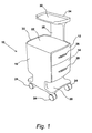
- FIGs 1 and 2 show the cabinet with each of the drawers 12 and 14 closed.
- this closed position is defined by engagement between the front of the drawer (visible in Figure 1 ) and the corresponding end of the body 10, so each of the drawers 12 and 14 is stopped in its closed position and will not move any further through the body 10.
- each drawer can be pulled out from the end in which it was inserted but it cannot move in the other direction. If required, the drawer can be removed from the end in which it was inserted and then reinserted in the other end, and then the drawer can only be pulled out from that end.
- each of the drawers 12 and 14 In the closed position, the fronts of each of the drawers 12 and 14 are slightly recessed relative to the corresponding end of the body 10, to combat the possibility of leakage into the drawers 12 and 14 in the event of some spillage on the cabinet. Similarly the backs of the drawers 12 and 14 are recessed relative to the other end of the body 10, as can be seen in Figure 2 .
- the cabinet is not symmetrical, but rather has a well-defined proximal side which in use faces the patient's bed.
- the top 22 of the body 10 has a raised lip 32 along its distal edge and its two end edges, but not along its proximal edge.
- the shelf 30 has a raised lip 34 along its distal edge and its two end edges, but not along its proximal edge. The lips 32 and 34 contribute to both ward cleanliness and patient convenience.
- FIG. 5 shows that the drawer 12 (which is shown open in Figure 5 ) has sides 12a which are of dished form so as to be of reduced height between front and back.
- the drawer 14 has similar sides. This arrangement makes it easier for a patient in bed to reach into either of the drawers 12 and 14 to access their contents.
- the body 10 is open from end to end, between its proximal wall 16 and its distal wall 18.
- the proximal wall 16 and the distal wall 18 each carry runners 36 on their inside faces, whereby the drawers 12 and 14 are mounted for opening and closing movement in the body 10.
- each of the runners 36 is equipped with a detent or 'bump point' operative to check the drawers 12 and 14 against being pulled completely out of the body 10. In well known fashion, if either of the drawers 12 and 14 is required to be removed, it is tilted to clear the bump point.
- the clearance below the platform 20 stems from the use of relatively large castors 24, which are 100mm diameter, and makes it easier to see and dust or other dirt accumulating under the cabinet.
- the large diameter of the castors 24 makes it easier to move the cabinet for cleaning the floor underneath it.
- the platform 20 is formed with shoulders which extend outwardly over the castors 24 to serve as buffers while the cabinet is being moved. Between these shoulders the platform 20 is somewhat reduced in length and breadth, further improving visibility below the cabinet.
- a second reason for removing the drawers 12 and 14 is to adapt the cabinet to a new location as follows.
- the proximal wall 16 of the body 10 is intended to be adjacent one side of a patient's bed.
- the proximal wall 16 will naturally face the right-hand side of the bed, as viewed from the foot of the bed, so that the drawers 12 and 14 open forwards generally towards the foot of the bed.
- the cabinet is instead to be located on the left-hand side of the bed, the cabinet needs to be turned around so that its proximal wall 16 faces the left-hand side of the bed. So that the drawers 12 and 14 open forwards in this location, they are simply removed from one end of the body 10 and re-inserted from the other end.
- a cabinet according to the invention is economical in that with minimal effort it can be configured for location on either side of a patient's bed whilst still offering the patient the benefits of proximal shaping of the body 10 and forward opening of the drawers 12 and 14. Further, when a plurality of cabinets are moved, for instance for pressure washing at a central cleansing station, it is not necessary label them with their locations, or even to keep their components together, because the bodies and drawers are of common form and cabinets can be assembled from them to fit any location.
- the cabinet of the invention is formed with two hooks 38 whereon coats etc may conveniently be hung. It will be noted that the hooks 38 are on the distal side of the upstand 28, where they are away from the patient's bed and easily accessed by visitors to the patient.
- Figure 4 makes it clear that the handles 26 on the drawers 12 and 14 are each upturned, which makes it easier for a patient to open the drawers 12 and 14, particularly from the bed, because the patient will most naturally use his or her upper hand for this, and the fingers on the upper hand will most comfortably point downwards to hook over an upturned handle 26.
- the cabinet may be equipped with only one drawer, or with more than the two described.
- at least one drawer may be provided with a lock, for security; and to avoid providing an unnecessary dirt-trap it is recommended that this lock be electronic or otherwise arranged to require no keyhole.
- the rim 34 of the shelf 30 may be formed along its distal edge to carry a patient care accessory such as a holder for alcohol gel or a glove box or a sharps bin.
Landscapes
- Accommodation For Nursing Or Treatment Tables (AREA)
- Handcart (AREA)
Abstract
Description
- The present invention relates to a cabinet for use beside a bed, of the type in which the cabinet comprises a body and a drawer in said body having a closed position defined by engagement with the body.
- In hospitals, care homes, hospices and like institutions it is normal to provide a cabinet beside each bed whereby patients may have their personal belongings and items of food and drink readily to hand. In such institutions the bedside cabinet needs to meet two linked criteria, namely affordability and cleanliness.
- With regard to affordability, the first factor to be considered is cost of manufacture. A very large organisation such as a public health service procures furniture in very large quantities, which drives down the unit cost. However, the very size of the organisation creates a great variety of locations for such furniture: even in a single hospital, wards may be differently arranged, especially if they have different functions. For the bedside cabinet the most basic variation is between placing the cabinet to the left or the right of the patient's bed. In the past this had led to cabinets which are essentially symmetrical about a centre line and can therefore be placed on either side of the bed. But such a cabinet has two notable disadvantages. First, it faces the front, whereas for much of the time the patient is to the side. Second, it has a back, which gives rise to cleaning problems (particular inside the cabinet, when the back is closed, as it conventionally is.
- A great upsurge in hospital acquired infection over recent years has focussed renewed attention on the need for cleanliness in hospitals. A rigorously enforced hygiene code is the only effective counter to Methicillin-resistant Staphylococcus aureus (MRSA) and Clostridium difficile (C. difficile) which are both now established in many hospitals, and also to outbreaks of norovirus; and a major component in this is ensuring cleanliness in and beside the bed, particularly in wards with rapid patient turnover and high bed occupancy. The need for cleanliness has financial implications in that the hygiene code must itself be affordable, and because patients who do become infected inevitably stay longer in hospital, creating an extra financial burden.
- According to an aspect of the present invention, there is provided a cabinet for use beside a bed of the aforesaid type, characterised in that the drawer may be inserted into the body alternatively from each of two opposite ends of the body and said engagement is such that the drawer may be withdrawn from the end whereby it has been inserted but not from the other end of the body.
- By inserting the drawer from one of the said ends, the cabinet may be arranged so that the drawer opens forwards (ie generally towards the foot of the bed) when the cabinet is on one side of the bed. If the cabinet is required to be placed on the other side of the bed then by inserting the drawer from the other of the said ends it will still open forwards. Those skilled in the art will appreciate that this is particularly convenient when cabinets are taken to be spray cleaned at a central station and may afterwards not be returned to their former locations.
- Preferably, to facilitate cleaning, the body of the cabinet is open at and between said opposite ends.
- As an additional aid to cleanliness, the drawer preferably has a front and a back which in the closed position of the drawer are each recessed from said ends. This means that spillage on the cabinet will not seep into the drawer.
- The drawer may have sides extending between its front and its back, which sides are of reduced height between front and back. This makes it easier for a patient to access the drawer from the bed.
- Preferably the body of the cabinet comprises a proximal wall disposed in use adjacent a side of the bed and a distal wall opposite the proximal wall, the drawer lying between said walls and the body being otherwise open therebetween. The proximal wall and the distal wall are preferably each formed with a runner to carry the drawer in sliding engagement therewith, and the runners may be formed with a detent operative to check the drawer against removal from the body.
- The body of the cabinet preferably comprises a top extending between the proximal and distal walls, and this top may be formed with a raised rim extending along its distal edge and orthogonally thereto in line with each of said opposite ends. The body may also comprise an upstand extending upwards from said top and carrying a shelf extending at least partly over said top, and this shelf may be formed with a raised rim extending along its distal edge and orthogonally thereto parallel with each of said opposite ends. With this arrangement the rim along the distal edge of the shelf may be configured and arranged to carry a patient care accessory such as a holder for alcohol gel, gloves or a sharps box. In addition the upstand may be formed with one or more hooks on its distal face.
- The body of the cabinet preferably includes a platform from which the proximal wall and the distal wall each extend upward. The cabinet preferably includes castors underneath the platform whereby the cabinet may be moved, and the platform may be formed with outwardly extending shoulders providing buffers while the cabinet is being moved.
- The cabinet may comprise two said drawers.
- Preferably the body of the cabinet and the or each drawer are each formed in one piece from synthetic plastics material, which may be done by rotational moulding. Preferably, too, all edges in the body and in the or each drawer are rounded, for ease of cleaning.
- The or each drawer may formed with an upturned handle. Also the cabinet may include a lock, preferably without a keyhole, for at least one said drawer.
- Other features of the invention will be apparent from the following description, which is made by way of example only and with reference to the accompanying schematic drawings in which -
-
Figure 1 is an isometric view of a bedside cabinet embodying the invention, viewed from its proximal side and one end, the cabinet including two drawers; -
Figure 2 is an isometric view of the bedside cabinet, viewed from its distal side and the other end; -
Figure 3 shows the cabinet in elevation, viewed from the front; -
Figure 4 shows the cabinet in elevation, viewed from its proximal side; -
Figure 5 is a view of the cabinet corresponding toFigure 1 showing one drawer open; and -
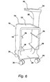
Figure 6 is a view of the cabinet corresponding toFigure 1 showing both drawers removed. - The following description of the invention begins with an overview with reference to all the figures, which use the same reference numerals throughout.
- The bedside cabinet shown in the drawings comprises a body indicated generally at 10, and an
upper drawer 12 and alower drawer body 10. Thebody 10 comprises aproximal wall 16 and adistal wall 18 each extending upward from a generallyhorizontal platform 20, and a generallyhorizontal top 22 extending between theproximal wall 16 and thedistal wall 18. Underneath the platform are fourcastors 24 whereby the cabinet may be readily moved, for cleaning and/or redeployment. Each of thedrawers handle 26. Anupstand 28 extends upward from thetop 22 and carries a generallyhorizontal shelf 30 extending partly over thetop 22. - The
body 10 and each of thedrawers - It may be noted here that the synthetic plastics material used in the manufacture of the cabinet could include an antimicrobial additive to inhibit the growth of bacteria. However research suggests that some healthcare staff may be less scrupulous about cleaning furniture including such an additive and therefore it is preferred to omit it from the present invention.
- The invention having been described in outline, more particular features will now be described.
- Referring to
Figures 1 and2 , these show the cabinet with each of thedrawers drawers Figure 1 ) and the corresponding end of thebody 10, so each of thedrawers body 10. In other words, each drawer can be pulled out from the end in which it was inserted but it cannot move in the other direction. If required, the drawer can be removed from the end in which it was inserted and then reinserted in the other end, and then the drawer can only be pulled out from that end. - In the closed position, the fronts of each of the
drawers body 10, to combat the possibility of leakage into thedrawers drawers body 10, as can be seen inFigure 2 . - As can also be seen from the accompanying drawings, the cabinet is not symmetrical, but rather has a well-defined proximal side which in use faces the patient's bed. Thus the top 22 of the
body 10 has a raisedlip 32 along its distal edge and its two end edges, but not along its proximal edge. With the proximal wall of thebody 10 against the patient's bed, the patient can easily reach items on the top 22 of the cabinet such as books, fruit or a drink. If the drink or anything else is spilt on the top 22 thelip 32 channels it towards the proximal side of the cabinet, and away from the distal side where it could get on to the floor and be trodden across the ward. In the same way, and for the same reasons, theshelf 30 has a raisedlip 34 along its distal edge and its two end edges, but not along its proximal edge. Thelips - Another contribution to patient convenience will now be described with reference to
Figure 5 . This shows that the drawer 12 (which is shown open inFigure 5 ) has sides 12a which are of dished form so as to be of reduced height between front and back. Thedrawer 14 has similar sides. This arrangement makes it easier for a patient in bed to reach into either of thedrawers - Referring now to
Figure 6 and considering this alongsideFigure 2 , it will be understood that thebody 10 is open from end to end, between itsproximal wall 16 and itsdistal wall 18. Theproximal wall 16 and thedistal wall 18 each carryrunners 36 on their inside faces, whereby thedrawers body 10. Although not detailed in the drawings (and this is considered unnecessary because it will be readily understood by those skilled in the art) each of therunners 36 is equipped with a detent or 'bump point' operative to check thedrawers body 10. In well known fashion, if either of thedrawers - One reason for removing the
drawers body 10 makes this easily done both in situ (using a cleaning cloth or the like) or at a central cleansing station where the cabinet may be pressure-washed and disinfected. Those skilled in the art will understand also that cleanliness is a matter of visibility as well as cleanability - that is, it is much easier to keep something clean when it is not hidden away. This is accomplished in the present invention by the open form of thebody 10 and also (seeFigure 3 especially) by the clearance both above and below theplatform 20. The clearance above theplatform 20, which derives from the form of the proximal anddistal walls platform 20. The clearance below theplatform 20 stems from the use of relativelylarge castors 24, which are 100mm diameter, and makes it easier to see and dust or other dirt accumulating under the cabinet. - It should also be understood that the large diameter of the
castors 24 makes it easier to move the cabinet for cleaning the floor underneath it. Further, as can be seen clearly fromFigure 1 for instance, theplatform 20 is formed with shoulders which extend outwardly over thecastors 24 to serve as buffers while the cabinet is being moved. Between these shoulders theplatform 20 is somewhat reduced in length and breadth, further improving visibility below the cabinet. - A second reason for removing the
drawers proximal wall 16 of thebody 10 is intended to be adjacent one side of a patient's bed. Thus, as configured for instance inFigure 1 , theproximal wall 16 will naturally face the right-hand side of the bed, as viewed from the foot of the bed, so that thedrawers proximal wall 16 faces the left-hand side of the bed. So that thedrawers body 10 and re-inserted from the other end. - It follows from the above that a cabinet according to the invention is economical in that with minimal effort it can be configured for location on either side of a patient's bed whilst still offering the patient the benefits of proximal shaping of the
body 10 and forward opening of thedrawers - Hospital wards are commonly short of hanging space for clothing. As can be seen from
Figure 2 , the cabinet of the invention is formed with twohooks 38 whereon coats etc may conveniently be hung. It will be noted that thehooks 38 are on the distal side of theupstand 28, where they are away from the patient's bed and easily accessed by visitors to the patient. - Finally,
Figure 4 makes it clear that thehandles 26 on thedrawers drawers upturned handle 26. - Various modifications to and adaptations of the cabinet described may be made without departing from the scope of the invention. For instance, the cabinet may be equipped with only one drawer, or with more than the two described. Also, at least one drawer may be provided with a lock, for security; and to avoid providing an unnecessary dirt-trap it is recommended that this lock be electronic or otherwise arranged to require no keyhole. The
rim 34 of theshelf 30 may be formed along its distal edge to carry a patient care accessory such as a holder for alcohol gel or a glove box or a sharps bin. - It should also be noted that, whilst the invention has been described with reference to a bedside cabinet for use in hospitals and the like, its use is not necessarily so limited. For instance it might be adapted for use as a chairside trolley in a doctor's or dentist's surgery; or it could be used outside the healthcare field altogether, for instance in hotels, where a robust construction, adaptability of location and easy-cleaning are all important.
- Other possible modifications and adaptations will be apparent to those skilled in the art.
Claims (23)
- A cabinet for use beside a bed, which cabinet comprises a body and a drawer in said body having a closed position defined by engagement with the body, characterised in that the drawer may be inserted into the body alternatively from each of two opposite ends of the body and said engagement is such that the drawer may be withdrawn from the end whereby it has been inserted but not from the other end of the body.
- A cabinet for use beside a bed as claimed in claim 1 characterised in that the body is open at and between said opposite ends.
- A cabinet for use beside a bed as claimed in claim 1 or claim 2 characterised in that the drawer has a front and a back which in the closed position of the drawer are each recessed from said ends.
- A cabinet for use beside a bed as claimed in claim 3 characterised in that the drawer has sides extending between its front and its back, which sides are of reduced height between front and back.
- A cabinet for use beside a bed as claimed in any preceding claim characterised in that the body comprises a proximal wall disposed in use adjacent a side of the bed and a distal wall opposite the proximal wall, the drawer lying between said walls and the body being otherwise open therebetween.
- A cabinet for use beside a bed as claimed in claim 5 characterised in that the proximal wall and the distal wall are each formed with a runner to carry the drawer in sliding engagement therewith.
- A cabinet for use beside a bed as claimed in claim 6 characterised in that the runners are formed with a detent operative to check the drawer against removal from the body.
- A cabinet for use beside a bed as claimed in any of claims 5 to 7 characterised in that the body comprises a top extending between the proximal and distal walls.
- A cabinet for use beside a bed as claimed in claim 8 characterised in that said top is formed with a raised rim extending along its distal edge and orthogonally thereto in line with each of said opposite ends.
- A cabinet for use beside a bed as claimed in claim 9 characterised in that the body comprises an upstand extending upwards from said top and carrying a shelf extending at least partly over said top.
- A cabinet for use beside a bed as claimed in claim 10 characterised in that the shelf is formed with a raised rim extending along its distal edge and orthogonally thereto parallel with each of said opposite ends.
- A cabinet for use beside a bed as claimed in claim 11 characterised in that the rim along the distal edge of the shelf is configured and arranged to carry a patient care accessory.
- A cabinet for use beside a bed as claimed in any of claims 10 to 12 characterised in that the upstand is formed with one or more hooks on its distal end.
- A cabinet for use beside a bed as claimed in any of claims 5 to 13 characterised in that the body includes a platform from which the proximal wall and the distal wall each extend upward.
- A cabinet for use beside a bed as claimed in claim 14 characterised in that the cabinet includes castors underneath the platform whereby the cabinet may be moved.
- A cabinet for use beside a bed as claimed in claim 14 or claim 15 characterised in that the platform is formed with outwardly extending shoulders providing buffers while the cabinet is being moved.
- A cabinet for use beside a bed as claimed in any preceding claim characterised in that the cabinet comprises two said drawers.
- A cabinet for use beside a bed as claimed in any preceding claim characterised in that the body and the or each drawer are each formed in one piece from synthetic plastics material.
- A cabinet for use beside a bed as claimed in claim 18 characterised in that the body and the or each drawer are formed by rotational moulding.
- A cabinet for use beside a bed as claimed in claim 18 or claim 19 characterised in that in the body and in the or each drawer all edges are rounded.
- A cabinet for use beside a bed as claimed in any preceding claim characterised in that the or each drawer is formed with an upturned handle.
- A cabinet for use beside a bed as claimed in any preceding claim characterised in that the cabinet includes a lock for at least one said drawer.
- A cabinet for use beside a bed as claimed in claim 22 characterised in that the lock has no keyhole.
Applications Claiming Priority (1)
| Application Number | Priority Date | Filing Date | Title |
|---|---|---|---|
| GBGB0906666.3A GB0906666D0 (en) | 2009-04-17 | 2009-04-17 | Cabinet |
Publications (3)
| Publication Number | Publication Date |
|---|---|
| EP2241215A2 true EP2241215A2 (en) | 2010-10-20 |
| EP2241215A3 EP2241215A3 (en) | 2011-10-19 |
| EP2241215B1 EP2241215B1 (en) | 2013-08-07 |
Family
ID=40774581
Family Applications (1)
| Application Number | Title | Priority Date | Filing Date |
|---|---|---|---|
| EP10250785.2A Active EP2241215B1 (en) | 2009-04-17 | 2010-04-15 | Cabinet |
Country Status (3)
| Country | Link |
|---|---|
| US (1) | US8651594B2 (en) |
| EP (1) | EP2241215B1 (en) |
| GB (1) | GB0906666D0 (en) |
Cited By (3)
| Publication number | Priority date | Publication date | Assignee | Title |
|---|---|---|---|---|
| GB2482527A (en) * | 2010-08-05 | 2012-02-08 | David Swann | Receptacle allowing wipe through cleaning for infection control |
| DK201600428A1 (en) * | 2016-07-16 | 2018-01-29 | Andreas Lolle | Hight-adjustable bedside table |
| CN110292258A (en) * | 2019-07-01 | 2019-10-01 | 郑州职业技术学院 | A kind of bookshelf collating unit and matched method for sorting |
Families Citing this family (17)
| Publication number | Priority date | Publication date | Assignee | Title |
|---|---|---|---|---|
| US20110018412A1 (en) * | 2009-07-23 | 2011-01-27 | Rosemary Swanek | Mobile sanitization station |
| US9033154B2 (en) * | 2011-10-04 | 2015-05-19 | Dovette DeVore | Infection prevention system with IV pole flush and swab caddy |
| US10453572B1 (en) | 2012-03-01 | 2019-10-22 | Capsa Solutions, Llc | System and method for a hospital cart |
| USD863559S1 (en) * | 2013-03-01 | 2019-10-15 | Capsa Solutions, Llc | Hospital cart |
| USD737452S1 (en) * | 2013-11-26 | 2015-08-25 | Fnt Co., Ltd. | Apparatus for medical analysis |
| USD882819S1 (en) * | 2018-03-23 | 2020-04-28 | Modo, Inc. | Quick connect platform for retaining medical devices |
| USD977110S1 (en) * | 2018-05-21 | 2023-01-31 | Draeger Medical Systems, Inc. | Neonatal care device |
| USD936230S1 (en) * | 2019-01-29 | 2021-11-16 | Ulthera, Inc. | Medical treatment cart |
| US20220151376A1 (en) * | 2020-11-17 | 2022-05-19 | Janelle White | System and method for improved overbed table |
| USD992119S1 (en) * | 2021-07-20 | 2023-07-11 | Symap Medical (Suzhou), Limited | Medical trolley |
| USD991461S1 (en) * | 2021-07-20 | 2023-07-04 | Symap Medical (Suzhou), Limited | Medical trolley |
| USD991460S1 (en) * | 2021-07-20 | 2023-07-04 | Symap Medical (Suzhou), Limited | Medical trolley |
| USD995792S1 (en) * | 2021-11-27 | 2023-08-15 | Sphaira Medical Gmbh | Trolley for medical care |
| USD995793S1 (en) * | 2021-11-27 | 2023-08-15 | Sphaira Medical Gmbh | Trolley for medical care |
| JP1812347S (en) * | 2025-01-16 | 2025-11-07 | Medical X-ray machine | |
| JP1812399S (en) * | 2025-01-16 | 2025-11-07 | Medical X-ray machine | |
| USD1140008S1 (en) | 2025-05-02 | 2026-08-04 | Empyrean Medical Systems, Inc. | X-ray irradiator |
Family Cites Families (41)
| Publication number | Priority date | Publication date | Assignee | Title |
|---|---|---|---|---|
| US628322A (en) * | 1897-05-05 | 1899-07-04 | John M Hoffmire | Drawer-centering device. |
| US2272819A (en) * | 1939-03-06 | 1942-02-10 | William C Poetsch | Hospital table |
| US2404851A (en) * | 1942-01-23 | 1946-07-30 | Knowles | Refrigerated locker |
| US2565784A (en) * | 1949-01-17 | 1951-08-28 | Jack F Sheean | Filing cabinet equipment for machine shops |
| US3222117A (en) * | 1963-03-08 | 1965-12-07 | Advance Food Service Equipment | Storage rack |
| US3285685A (en) * | 1964-07-30 | 1966-11-15 | Frank W Hewett | Furniture |
| US3314741A (en) * | 1965-10-13 | 1967-04-18 | Curtis Electro Lighting Inc | Medicine cabinet body |
| US3524691A (en) * | 1968-03-18 | 1970-08-18 | Watson Mfg Co | File drawer |
| US3529880A (en) * | 1968-12-18 | 1970-09-22 | Art Metal Knoll Corp | Storage module |
| US3868123A (en) * | 1973-12-10 | 1975-02-25 | Rubbermaid Commercial Products | Food service storage vehicle |
| US3963125A (en) * | 1975-01-23 | 1976-06-15 | Crescent Metal Products, Inc. | Rack for storing trays or the like |
| US4178049A (en) * | 1978-07-10 | 1979-12-11 | Lyon Metal Products, Incorporated | Shelf box with dual pivoting stop mechanism |
| US4588096A (en) * | 1985-09-09 | 1986-05-13 | Standex International Corporation | Knock-down tray rack |
| US4822116A (en) * | 1987-04-06 | 1989-04-18 | Drustar Inc. | Back-to-back drawer assembly with staggered bypassing slides |
| US5016948A (en) * | 1989-02-02 | 1991-05-21 | Intermetro Industries Corporation | Modular utility cart |
| US5011240A (en) * | 1989-11-28 | 1991-04-30 | Milcare, Inc. | Segmented side wall cart |
| US5094418A (en) * | 1990-09-07 | 1992-03-10 | Stryker Corporation | IV pole |
| US5259668A (en) * | 1991-03-01 | 1993-11-09 | Artromick International Inc. | Cart for medication |
| US5306077A (en) * | 1991-10-04 | 1994-04-26 | Megaspace Pty Ltd. | Drawer unit for displaying and dispensing of merchandise |
| JPH08191720A (en) * | 1995-01-13 | 1996-07-30 | Inax Corp | Wagon with drawer |
| US5829767A (en) * | 1996-03-07 | 1998-11-03 | Grossman; Glenn D. | Knock-down cart |
| US5795043A (en) * | 1996-11-01 | 1998-08-18 | The Protectoseal Company | Corrosion-resistant storage cabinet |
| US5873643A (en) * | 1996-12-10 | 1999-02-23 | Burgess, Jr.; Joseph | Multi-compartment cabinet |
| US5839806A (en) * | 1997-05-30 | 1998-11-24 | Liu; Ching-Rong | Support and drawer structure of drawer type storage shelf |
| USD408953S (en) * | 1998-05-15 | 1999-04-27 | Rubbermaid Commercial Products Inc. | Food service storage cart |
| JP2000197530A (en) * | 1999-01-06 | 2000-07-18 | Sekisui House Ltd | Chest of drawers |
| US6626445B2 (en) * | 1999-12-02 | 2003-09-30 | Alcon Universal Ltd. | Cart for surgical console |
| US6729371B2 (en) * | 2001-02-05 | 2004-05-04 | Kevin Sheahan | Workbench |
| WO2003099066A1 (en) * | 2002-05-23 | 2003-12-04 | Rubbermaid Incorporated | Flat panel assembly for a drawer tower |
| NL1021522C2 (en) * | 2002-09-24 | 2004-03-25 | Driessen Aircraft Holding B V | Drawer, assembly of drawer cabinet and drawer as well as plane or train provided with such an assembly. |
| US6926376B2 (en) * | 2002-12-30 | 2005-08-09 | Whirlpool Corporation | Modular workbench system |
| US20040262867A1 (en) * | 2003-02-24 | 2004-12-30 | Rubbermaid Commercial Products Llc | Medical cart, medication module, height adjustment mechanism, and method of medication transport |
| JP2008501876A (en) * | 2004-06-03 | 2008-01-24 | ヒル−ロム サービシーズ,インコーポレイティド | Modular system for building hospital walls |
| EP1716778B1 (en) * | 2005-04-26 | 2011-05-11 | Peka-Metall AG | Drawer for a freestanding body being bilaterally extensible |
| US7513000B2 (en) * | 2005-07-28 | 2009-04-07 | The Brewer Company, Llc | Medical examination table |
| CA2545978A1 (en) * | 2006-05-08 | 2007-11-08 | Gracious Living Corporation | Drawer unit |
| US7673952B2 (en) * | 2006-06-14 | 2010-03-09 | Gordon Bud Jeansonne | Medical treatment cart |
| US8322732B2 (en) * | 2006-06-16 | 2012-12-04 | Bradyquin, Llc | Portable workstation |
| CN201101664Y (en) * | 2007-09-18 | 2008-08-20 | 天津市天津医院 | Transfusion trolley for medical use |
| USD632796S1 (en) * | 2008-12-12 | 2011-02-15 | Nellcor Puritan Bennett Llc | Medical cart |
| TWM366457U (en) * | 2009-05-19 | 2009-10-11 | Hardware Buyers Source Inc | Tool storage unit |
-
2009
- 2009-04-17 GB GBGB0906666.3A patent/GB0906666D0/en not_active Ceased
-
2010
- 2010-04-15 EP EP10250785.2A patent/EP2241215B1/en active Active
- 2010-04-16 US US12/762,061 patent/US8651594B2/en not_active Expired - Fee Related
Non-Patent Citations (1)
| Title |
|---|
| None |
Cited By (3)
| Publication number | Priority date | Publication date | Assignee | Title |
|---|---|---|---|---|
| GB2482527A (en) * | 2010-08-05 | 2012-02-08 | David Swann | Receptacle allowing wipe through cleaning for infection control |
| DK201600428A1 (en) * | 2016-07-16 | 2018-01-29 | Andreas Lolle | Hight-adjustable bedside table |
| CN110292258A (en) * | 2019-07-01 | 2019-10-01 | 郑州职业技术学院 | A kind of bookshelf collating unit and matched method for sorting |
Also Published As
| Publication number | Publication date |
|---|---|
| EP2241215B1 (en) | 2013-08-07 |
| US8651594B2 (en) | 2014-02-18 |
| EP2241215A3 (en) | 2011-10-19 |
| US20100264784A1 (en) | 2010-10-21 |
| GB0906666D0 (en) | 2009-06-03 |
Similar Documents
| Publication | Publication Date | Title |
|---|---|---|
| EP2241215B1 (en) | Cabinet | |
| EP2275069A2 (en) | Siderail with storage area | |
| US4586762A (en) | Door and drawer front having a recessed grasping surface | |
| JP2011524206A (en) | Bedside article support apparatus and system | |
| US20080012257A1 (en) | Portable bedside toileting storage system | |
| WO2016161461A1 (en) | Disposable sanitary tray and bedside tables | |
| CN208243224U (en) | A kind of novel multifunctional medical cabinet | |
| CN202529448U (en) | Integral type medical waste sorting storage cabinet | |
| US11350733B1 (en) | Reversibly mounted sliding surface extension tray | |
| CN209153984U (en) | A kind of multipurpose integral type therapeutic endoscopy vehicle | |
| EP1464252A2 (en) | Cabinet moulded in one piece | |
| CN212394355U (en) | Bed cabinet integrated multifunctional medical bedside cabinet | |
| JP3214877U (en) | Diaper changing table | |
| CN208405176U (en) | Article placing shelf for sickbed | |
| CN215021249U (en) | A special treatment vehicle for isolated patients | |
| CN209790281U (en) | surgery postoperative care shallow | |
| CN209422340U (en) | Mobile phlegm-aspiration rack | |
| CN208388199U (en) | Multi-functional ward nursing cabinet | |
| CN215126007U (en) | A multifunctional medical bedside table | |
| CN215875364U (en) | Bracket is used in tumour chemotherapy nursing convenient to clearance | |
| CN222816011U (en) | Special treatment car of dialysis | |
| CN2768743Y (en) | Multifunction nursing cart for baby | |
| CN203915346U (en) | A peritoneal dialysis external short tube replacement vehicle | |
| CN209751492U (en) | PICC table chair of changing dressings | |
| CN216723754U (en) | Multifunctional bedside table suitable for old people lying in bed |
Legal Events
| Date | Code | Title | Description |
|---|---|---|---|
| PUAI | Public reference made under article 153(3) epc to a published international application that has entered the european phase |
Free format text: ORIGINAL CODE: 0009012 |
|
| AK | Designated contracting states |
Kind code of ref document: A2 Designated state(s): AT BE BG CH CY CZ DE DK EE ES FI FR GB GR HR HU IE IS IT LI LT LU LV MC MK MT NL NO PL PT RO SE SI SK SM TR |
|
| AX | Request for extension of the european patent |
Extension state: AL BA ME RS |
|
| RIN1 | Information on inventor provided before grant (corrected) |
Inventor name: THOMPSON, CHRISTOPHER IAN Inventor name: OPEN, PAUL Inventor name: BEVIS, MARK Inventor name: JONES, BRYN Inventor name: WIGHTMAN, CRAIG IAN |
|
| PUAL | Search report despatched |
Free format text: ORIGINAL CODE: 0009013 |
|
| AK | Designated contracting states |
Kind code of ref document: A3 Designated state(s): AT BE BG CH CY CZ DE DK EE ES FI FR GB GR HR HU IE IS IT LI LT LU LV MC MK MT NL NO PL PT RO SE SI SK SM TR |
|
| AX | Request for extension of the european patent |
Extension state: AL BA ME RS |
|
| RIC1 | Information provided on ipc code assigned before grant |
Ipc: A47B 55/00 20060101AFI20110912BHEP Ipc: A47B 88/00 20060101ALI20110912BHEP |
|
| 17P | Request for examination filed |
Effective date: 20120418 |
|
| 17Q | First examination report despatched |
Effective date: 20120913 |
|
| GRAP | Despatch of communication of intention to grant a patent |
Free format text: ORIGINAL CODE: EPIDOSNIGR1 |
|
| RIN1 | Information on inventor provided before grant (corrected) |
Inventor name: JONES, BRYN Inventor name: OPEN, PAUL Inventor name: BEVIS, MARK Inventor name: WIGHTMAN, CRAIG IAN Inventor name: THOMPSON, CHRISTOPHER IAN |
|
| GRAS | Grant fee paid |
Free format text: ORIGINAL CODE: EPIDOSNIGR3 |
|
| GRAA | (expected) grant |
Free format text: ORIGINAL CODE: 0009210 |
|
| AK | Designated contracting states |
Kind code of ref document: B1 Designated state(s): AT BE BG CH CY CZ DE DK EE ES FI FR GB GR HR HU IE IS IT LI LT LU LV MC MK MT NL NO PL PT RO SE SI SK SM TR |
|
| REG | Reference to a national code |
Ref country code: GB Ref legal event code: FG4D |
|
| REG | Reference to a national code |
Ref country code: AT Ref legal event code: REF Ref document number: 625321 Country of ref document: AT Kind code of ref document: T Effective date: 20130815 Ref country code: CH Ref legal event code: EP |
|
| REG | Reference to a national code |
Ref country code: IE Ref legal event code: FG4D |
|
| REG | Reference to a national code |
Ref country code: DE Ref legal event code: R096 Ref document number: 602010009179 Country of ref document: DE Effective date: 20131002 |
|
| REG | Reference to a national code |
Ref country code: AT Ref legal event code: MK05 Ref document number: 625321 Country of ref document: AT Kind code of ref document: T Effective date: 20130807 |
|
| REG | Reference to a national code |
Ref country code: NL Ref legal event code: VDEP Effective date: 20130807 |
|
| REG | Reference to a national code |
Ref country code: LT Ref legal event code: MG4D |
|
| PG25 | Lapsed in a contracting state [announced via postgrant information from national office to epo] |
Ref country code: SE Free format text: LAPSE BECAUSE OF FAILURE TO SUBMIT A TRANSLATION OF THE DESCRIPTION OR TO PAY THE FEE WITHIN THE PRESCRIBED TIME-LIMIT Effective date: 20130807 Ref country code: CY Free format text: LAPSE BECAUSE OF FAILURE TO SUBMIT A TRANSLATION OF THE DESCRIPTION OR TO PAY THE FEE WITHIN THE PRESCRIBED TIME-LIMIT Effective date: 20130911 Ref country code: AT Free format text: LAPSE BECAUSE OF FAILURE TO SUBMIT A TRANSLATION OF THE DESCRIPTION OR TO PAY THE FEE WITHIN THE PRESCRIBED TIME-LIMIT Effective date: 20130807 Ref country code: LT Free format text: LAPSE BECAUSE OF FAILURE TO SUBMIT A TRANSLATION OF THE DESCRIPTION OR TO PAY THE FEE WITHIN THE PRESCRIBED TIME-LIMIT Effective date: 20130807 Ref country code: IS Free format text: LAPSE BECAUSE OF FAILURE TO SUBMIT A TRANSLATION OF THE DESCRIPTION OR TO PAY THE FEE WITHIN THE PRESCRIBED TIME-LIMIT Effective date: 20131207 Ref country code: PT Free format text: LAPSE BECAUSE OF FAILURE TO SUBMIT A TRANSLATION OF THE DESCRIPTION OR TO PAY THE FEE WITHIN THE PRESCRIBED TIME-LIMIT Effective date: 20131209 Ref country code: HR Free format text: LAPSE BECAUSE OF FAILURE TO SUBMIT A TRANSLATION OF THE DESCRIPTION OR TO PAY THE FEE WITHIN THE PRESCRIBED TIME-LIMIT Effective date: 20130807 Ref country code: NO Free format text: LAPSE BECAUSE OF FAILURE TO SUBMIT A TRANSLATION OF THE DESCRIPTION OR TO PAY THE FEE WITHIN THE PRESCRIBED TIME-LIMIT Effective date: 20131107 |
|
| PG25 | Lapsed in a contracting state [announced via postgrant information from national office to epo] |
Ref country code: FI Free format text: LAPSE BECAUSE OF FAILURE TO SUBMIT A TRANSLATION OF THE DESCRIPTION OR TO PAY THE FEE WITHIN THE PRESCRIBED TIME-LIMIT Effective date: 20130807 Ref country code: BE Free format text: LAPSE BECAUSE OF FAILURE TO SUBMIT A TRANSLATION OF THE DESCRIPTION OR TO PAY THE FEE WITHIN THE PRESCRIBED TIME-LIMIT Effective date: 20130807 Ref country code: GR Free format text: LAPSE BECAUSE OF FAILURE TO SUBMIT A TRANSLATION OF THE DESCRIPTION OR TO PAY THE FEE WITHIN THE PRESCRIBED TIME-LIMIT Effective date: 20131108 Ref country code: LV Free format text: LAPSE BECAUSE OF FAILURE TO SUBMIT A TRANSLATION OF THE DESCRIPTION OR TO PAY THE FEE WITHIN THE PRESCRIBED TIME-LIMIT Effective date: 20130807 Ref country code: SI Free format text: LAPSE BECAUSE OF FAILURE TO SUBMIT A TRANSLATION OF THE DESCRIPTION OR TO PAY THE FEE WITHIN THE PRESCRIBED TIME-LIMIT Effective date: 20130807 Ref country code: PL Free format text: LAPSE BECAUSE OF FAILURE TO SUBMIT A TRANSLATION OF THE DESCRIPTION OR TO PAY THE FEE WITHIN THE PRESCRIBED TIME-LIMIT Effective date: 20130807 Ref country code: NL Free format text: LAPSE BECAUSE OF FAILURE TO SUBMIT A TRANSLATION OF THE DESCRIPTION OR TO PAY THE FEE WITHIN THE PRESCRIBED TIME-LIMIT Effective date: 20130807 |
|
| PG25 | Lapsed in a contracting state [announced via postgrant information from national office to epo] |
Ref country code: CY Free format text: LAPSE BECAUSE OF FAILURE TO SUBMIT A TRANSLATION OF THE DESCRIPTION OR TO PAY THE FEE WITHIN THE PRESCRIBED TIME-LIMIT Effective date: 20130807 |
|
| PG25 | Lapsed in a contracting state [announced via postgrant information from national office to epo] |
Ref country code: EE Free format text: LAPSE BECAUSE OF FAILURE TO SUBMIT A TRANSLATION OF THE DESCRIPTION OR TO PAY THE FEE WITHIN THE PRESCRIBED TIME-LIMIT Effective date: 20130807 Ref country code: DK Free format text: LAPSE BECAUSE OF FAILURE TO SUBMIT A TRANSLATION OF THE DESCRIPTION OR TO PAY THE FEE WITHIN THE PRESCRIBED TIME-LIMIT Effective date: 20130807 Ref country code: CZ Free format text: LAPSE BECAUSE OF FAILURE TO SUBMIT A TRANSLATION OF THE DESCRIPTION OR TO PAY THE FEE WITHIN THE PRESCRIBED TIME-LIMIT Effective date: 20130807 Ref country code: RO Free format text: LAPSE BECAUSE OF FAILURE TO SUBMIT A TRANSLATION OF THE DESCRIPTION OR TO PAY THE FEE WITHIN THE PRESCRIBED TIME-LIMIT Effective date: 20130807 Ref country code: SK Free format text: LAPSE BECAUSE OF FAILURE TO SUBMIT A TRANSLATION OF THE DESCRIPTION OR TO PAY THE FEE WITHIN THE PRESCRIBED TIME-LIMIT Effective date: 20130807 |
|
| PG25 | Lapsed in a contracting state [announced via postgrant information from national office to epo] |
Ref country code: ES Free format text: LAPSE BECAUSE OF FAILURE TO SUBMIT A TRANSLATION OF THE DESCRIPTION OR TO PAY THE FEE WITHIN THE PRESCRIBED TIME-LIMIT Effective date: 20130807 Ref country code: IT Free format text: LAPSE BECAUSE OF FAILURE TO SUBMIT A TRANSLATION OF THE DESCRIPTION OR TO PAY THE FEE WITHIN THE PRESCRIBED TIME-LIMIT Effective date: 20130807 |
|
| PLBE | No opposition filed within time limit |
Free format text: ORIGINAL CODE: 0009261 |
|
| STAA | Information on the status of an ep patent application or granted ep patent |
Free format text: STATUS: NO OPPOSITION FILED WITHIN TIME LIMIT |
|
| 26N | No opposition filed |
Effective date: 20140508 |
|
| REG | Reference to a national code |
Ref country code: DE Ref legal event code: R097 Ref document number: 602010009179 Country of ref document: DE Effective date: 20140508 |
|
| PG25 | Lapsed in a contracting state [announced via postgrant information from national office to epo] |
Ref country code: LU Free format text: LAPSE BECAUSE OF FAILURE TO SUBMIT A TRANSLATION OF THE DESCRIPTION OR TO PAY THE FEE WITHIN THE PRESCRIBED TIME-LIMIT Effective date: 20140415 Ref country code: MC Free format text: LAPSE BECAUSE OF FAILURE TO SUBMIT A TRANSLATION OF THE DESCRIPTION OR TO PAY THE FEE WITHIN THE PRESCRIBED TIME-LIMIT Effective date: 20130807 |
|
| REG | Reference to a national code |
Ref country code: CH Ref legal event code: PL |
|
| PG25 | Lapsed in a contracting state [announced via postgrant information from national office to epo] |
Ref country code: CH Free format text: LAPSE BECAUSE OF NON-PAYMENT OF DUE FEES Effective date: 20140430 Ref country code: LI Free format text: LAPSE BECAUSE OF NON-PAYMENT OF DUE FEES Effective date: 20140430 |
|
| REG | Reference to a national code |
Ref country code: FR Ref legal event code: PLFP Year of fee payment: 6 |
|
| PGFP | Annual fee paid to national office [announced via postgrant information from national office to epo] |
Ref country code: IE Payment date: 20150225 Year of fee payment: 6 |
|
| PGFP | Annual fee paid to national office [announced via postgrant information from national office to epo] |
Ref country code: FR Payment date: 20150428 Year of fee payment: 6 |
|
| PG25 | Lapsed in a contracting state [announced via postgrant information from national office to epo] |
Ref country code: MT Free format text: LAPSE BECAUSE OF FAILURE TO SUBMIT A TRANSLATION OF THE DESCRIPTION OR TO PAY THE FEE WITHIN THE PRESCRIBED TIME-LIMIT Effective date: 20130807 |
|
| PG25 | Lapsed in a contracting state [announced via postgrant information from national office to epo] |
Ref country code: SM Free format text: LAPSE BECAUSE OF FAILURE TO SUBMIT A TRANSLATION OF THE DESCRIPTION OR TO PAY THE FEE WITHIN THE PRESCRIBED TIME-LIMIT Effective date: 20130807 |
|
| PG25 | Lapsed in a contracting state [announced via postgrant information from national office to epo] |
Ref country code: BG Free format text: LAPSE BECAUSE OF FAILURE TO SUBMIT A TRANSLATION OF THE DESCRIPTION OR TO PAY THE FEE WITHIN THE PRESCRIBED TIME-LIMIT Effective date: 20130807 |
|
| PG25 | Lapsed in a contracting state [announced via postgrant information from national office to epo] |
Ref country code: HU Free format text: LAPSE BECAUSE OF FAILURE TO SUBMIT A TRANSLATION OF THE DESCRIPTION OR TO PAY THE FEE WITHIN THE PRESCRIBED TIME-LIMIT; INVALID AB INITIO Effective date: 20100415 Ref country code: TR Free format text: LAPSE BECAUSE OF FAILURE TO SUBMIT A TRANSLATION OF THE DESCRIPTION OR TO PAY THE FEE WITHIN THE PRESCRIBED TIME-LIMIT Effective date: 20130807 |
|
| PGFP | Annual fee paid to national office [announced via postgrant information from national office to epo] |
Ref country code: DE Payment date: 20160308 Year of fee payment: 7 |
|
| REG | Reference to a national code |
Ref country code: IE Ref legal event code: MM4A |
|
| REG | Reference to a national code |
Ref country code: FR Ref legal event code: ST Effective date: 20161230 |
|
| PG25 | Lapsed in a contracting state [announced via postgrant information from national office to epo] |
Ref country code: FR Free format text: LAPSE BECAUSE OF NON-PAYMENT OF DUE FEES Effective date: 20160502 |
|
| PG25 | Lapsed in a contracting state [announced via postgrant information from national office to epo] |
Ref country code: IE Free format text: LAPSE BECAUSE OF NON-PAYMENT OF DUE FEES Effective date: 20160415 |
|
| REG | Reference to a national code |
Ref country code: DE Ref legal event code: R119 Ref document number: 602010009179 Country of ref document: DE |
|
| PG25 | Lapsed in a contracting state [announced via postgrant information from national office to epo] |
Ref country code: DE Free format text: LAPSE BECAUSE OF NON-PAYMENT OF DUE FEES Effective date: 20171103 |
|
| PG25 | Lapsed in a contracting state [announced via postgrant information from national office to epo] |
Ref country code: MK Free format text: LAPSE BECAUSE OF FAILURE TO SUBMIT A TRANSLATION OF THE DESCRIPTION OR TO PAY THE FEE WITHIN THE PRESCRIBED TIME-LIMIT Effective date: 20130807 |
|
| PGFP | Annual fee paid to national office [announced via postgrant information from national office to epo] |
Ref country code: GB Payment date: 20250219 Year of fee payment: 16 |