EP2241162B1 - Radio frequency antenna for heating devices - Google Patents
Radio frequency antenna for heating devices Download PDFInfo
- Publication number
- EP2241162B1 EP2241162B1 EP08729434.4A EP08729434A EP2241162B1 EP 2241162 B1 EP2241162 B1 EP 2241162B1 EP 08729434 A EP08729434 A EP 08729434A EP 2241162 B1 EP2241162 B1 EP 2241162B1
- Authority
- EP
- European Patent Office
- Prior art keywords
- antenna
- loops
- antenna assembly
- rfid tag
- conductive paths
- Prior art date
- Legal status (The legal status is an assumption and is not a legal conclusion. Google has not performed a legal analysis and makes no representation as to the accuracy of the status listed.)
- Active
Links
Images


Classifications
-
- H—ELECTRICITY
- H05—ELECTRIC TECHNIQUES NOT OTHERWISE PROVIDED FOR
- H05B—ELECTRIC HEATING; ELECTRIC LIGHT SOURCES NOT OTHERWISE PROVIDED FOR; CIRCUIT ARRANGEMENTS FOR ELECTRIC LIGHT SOURCES, IN GENERAL
- H05B6/00—Heating by electric, magnetic or electromagnetic fields
- H05B6/02—Induction heating
- H05B6/06—Control, e.g. of temperature, of power
- H05B6/062—Control, e.g. of temperature, of power for cooking plates or the like
-
- H—ELECTRICITY
- H05—ELECTRIC TECHNIQUES NOT OTHERWISE PROVIDED FOR
- H05B—ELECTRIC HEATING; ELECTRIC LIGHT SOURCES NOT OTHERWISE PROVIDED FOR; CIRCUIT ARRANGEMENTS FOR ELECTRIC LIGHT SOURCES, IN GENERAL
- H05B2213/00—Aspects relating both to resistive heating and to induction heating, covered by H05B3/00 and H05B6/00
- H05B2213/05—Heating plates with pan detection means
Definitions
- the present invention is broadly concerned with improved RF antenna assemblies used as a part of an induction or other type of heating apparatus in order to establish and maintain RF communication between the heating apparatus and an object being heated having a peripheral-mounted RF transponder. More particularly, it is concerned with such antenna assemblies, as well as overall heating systems and combinations thereof including heatable objects, making use of the improved RF antenna assemblies.
- the preferred RF antenna assemblies comprise multiple antenna loops cooperatively defining a substantially continuous RF communication zone outboard of a cooking hob.
- RF communications between a transmitter/receiver forming a part of the induction heater, and a radio frequency transponder (e.g., a RFID tag) associated with the object to be heated by the induction heater
- RF communications include transponder feedback that is use by the induction heater to alter and/or control the heating of the object.
- the transmitter/receivers of such systems also include an antenna designed to interrogate the transponder and to receive information therefrom. The position of the antenna relative to the work coil of the induction heater in these systems is important in establishing and maintaining the necessary RF communication, and in allowing the user some freedom of placement of the object while it is being heated.
- U.S. Patent No. 6,320,169 describes an induction heating system having a RFID antenna located at the center of the cooking hob, i.e., in the center of the heater's work coil.
- the object being heated can have a RFID tag affixed to the object's symmetry position, typically in the geometric center of the object.
- This symmetry position for both the RFID antenna and the RFID tag allows use of standard RFID antennas typically constructed of planar spiral or other geometric shape traces printed on a rigid substrate, with associated on-board capacitor(s) and other electronic components.
- This symmetry orientation allows the object to be heated to be rotated through a full 360E angular orientation while atop the hob, without loss of RFID communication.
- the RFID reader antenna preferably covers only a quadrant of the periphery of the work coil. Consequently, where the RFID tag is handle-mounted, the vessel must be maintained in a relatively small range of angular positions, else the necessary RF communication between the tag and reader will be lost. This presents a significant problem to the user, i.e., casual or even professional users may accidentally move the vessel handle out of the range of the RFID antenna during food preparation. Moreover, many users wish to place vessel handles in various different orientations for ease of food preparation or to ensure that a given handle is not inadvertently contacted, resulting in spillage.
- Japanese Publication No. 2006-294372 entitled “Heating Cooker” describes cooking systems wherein the communication area of the RFID system is varied by changing the electrified areas of the antenna. In other words, more or less of the traces of the antenna circuit are powered, based upon the stage of the cooking operation. Thus, before cooking is initiated, and before the pan handle is placed within the antenna zone, the smallest antenna area is electrified, thus making the antenna read range narrower so as to force the user to place the pan handle in the proper location relative to the electrified antenna area. Then, after cooking begins, more outlying antenna traces are electrified so as to have a wider reading area, and thus reduce the number of reading errors as the user rotates the pan handle during the cooking sequence.
- this system is inherently very complex, still only allows for RF communications over a limited portion of the periphery of the hob, and does not provide a full answer to the problem.
- No known prior art describes any structure or means which provides a RF antenna forming a part of a heating device for use with cookware, servingware, or other heatable objects equipped with peripheral-mounted RF transponders, wherein the object being heated can be rotated through substantially 360° and/or radially displaced without loss of RF communication between the transponder and heating device. Accordingly, there is a real and unsatisfied need in the art for an improved antenna useful with a variety of heating devices and which establishes a substantially continuous RF communication zone outboard of and substantially surrounding the hob(s) of the heating device, thereby allowing a user to rotate an object being heated having a peripheral RF transponder to virtually any desired angular position without communication loss.
- EP 1 229 482 A2 discloses a reader coil antenna for a non-contact type card reader. This coil comprises an outer coil and an inner coil disposed inside the outer coil. The coils are connected in series.
- US 6 953 919 B2 describes a system and a method for providing multiple cooking modes and an ability to automatically heat (by means of induction heating) cooking vessels and other objects using RFID technology.
- the present invention relates to an RF antenna assembly and to an induction heating system and is defined in claim 1 and in claim 8, respectively.
- Advantageous versions of the invention follow from the dependent claims.
- the present invention overcomes the problems outlined above and provides an RF antenna assembly normally forming a part of a heating apparatus including one or more heating hobs designed to heat an object.
- the antenna assembly is operable to communicate with an associated RF device peripherally coupled with the object, such as an RFID tag. Such RF communication is maintained even when the object is located at a variety of rotated or displaced positions relative to the heating hob through substantially 360° about the hob.
- the preferred antenna assembly of the invention broadly includes an antenna including a plurality of continuous, conductive antenna loops oriented to cooperatively and substantially surround the heating hob, with each of the loops having an inner section proximal to said hob and defining a respective, enclosed RF communication region outboard of the inner loop section, Such zones cooperatively define a substantially continuous RF communication zone outboard of and disposed about the hob.
- the antenna assembly also has circuitry including at least two conductive paths adapted for coupling with a signal generator, wherein the plurality of loops each has one terminal end connected to at least one of the conductive paths, and having a second terminal end connected to at least one other of the conductive paths.
- adjacent ends of the antenna loops are overlapped to cooperatively define a continuous RF communication zone outboard of and surrounding the hob.
- the plural, overlapped antenna loops ensure that there are no RF communication "dead zones" about the entire periphery of the hob.
- the antenna loops are not in electrical series, but are rather each connected to a signal generator such as a RFID reader or reader/writer.
- the antenna assembly is mounted on a substrate supporting the antenna loops and associated circuitry.
- the substrate presents a pair of opposed faces, with at least one of the antenna loops on one of the faces, and another of the loops on the other of the faces.
- all of the loops can be applied to one face of the substrate, so long as appropriate electrical connections are maintained with no series connections between the antenna loops.
- the antenna loops are advantageously formed as a pair of closely spaced apart, parallel copper traces. Tuning assemblies are also coupled with the loops in order to tune each of the antenna loops with reference to the signal generator's driving frequency,
- the antenna of the invention finds particular utility in induction heating systems for various objects including a component such as a heating hob for generating a magnetic field in order to inductively heat an object, with control circuitry operably coupled with the field-generating component in order to control the operation of the latter.
- control circuitry includes an RFID tag reader (or more preferably a RFID reader/writer) and the antenna of the invention coupled with the tag reader in order to interrogate a proximal RFID tag associated with the object being heated, and to receive information from the object-mounted (or object-associated) RFID tag.
- the antenna of this invention is especially advantageous for use with induction hobs because each of its plurality of loops provides very little penetration area for magnetic field lines emanating from the induction hob.
- each of the plurality of antenna loops experiences very little induced voltage (noise) due to time-changing flux from the hob's alternating magnetic field, and thus the signal-to-noise ratio of each of the plurality of antennas can be very high.
- This lack of induced noise is a great advantage over a single loop antenna configured to fully surround the induction hob, which experiences severe induced noise.
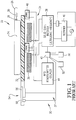
- FIGs. 1 and 2 a prior art induction heating apparatus 20 and associated heatable cooking vessel 22 are illustrated.
- This apparatus is of the type described in U.S. Patent No. 6,953,919 .
- FIGS. 1-10 depict an exemplary RFID-equipped cooking vessel 22 in the form of a pan or skillet having a food-holding section 24 and elongated handle 26.
- the handle 26 includes a resistant temperature sensing device 28 in thermal connection with the section 24, and an electrically coupled RFID tag 30.
- the heating apparatus 20 includes an upper support 32 adapted to support vessel 22 as shown.
- the apparatus 20 also includes one or more hobs 34 having a work coil 36 and associated ultrasonic frequency inverter 38 and rectifier 40.
- the vessel 22 is positioned directly above the hob 34 and work coil 36.
- the overall control circuitry 37 associated with the apparatus 20 includes a microprocessor 42, a RFID reader/writer 44, and one or more RFID antennas 46, 48.
- a real-time clock 50 and additional memory 52 are coupled with the microprocessor 42.
- the control circuitry 37 also includes a user interface 54, display 56, and input device 58.
- vessel 22 is located centrally within the confines of hob 34 and work coil 36, with antenna 48 located in a corner region at approximately a 7 o'clock position beneath the support 32 of heating apparatus 20.
- antenna 48 located in a corner region at approximately a 7 o'clock position beneath the support 32 of heating apparatus 20.
- the corner-mounted antenna 48 comes into play in the illustrated embodiment and provides inductive coupling and RF communication between the vessel 22 and heating apparatus 20. This in turn means that such RF communication can only occur when the handle 26 is positioned at approximately a 7 o'clock position directly above the antenna 48, as best illustrated in full lines in Fig. 2 .
- the apparatus 20 and vessel 22 are in RF communication for information exchange between the microprocessor 42 and RFID tag 30, when the handle 26 is substantially above the corner-mounted antenna 48.
- the heating apparatus 20 can be controlled over a sequence of predetermined heating steps.
- the heating apparatus 20 is designed to read a set of heating instructions from an external storage medium, and such instructions are used in conjunction with vessel temperature information received from RFID tag 30 during the course of vessel heating, to control the heating sequence for a particular food or recipe.
- the display 56 may prompt a user to add specific ingredients to the vessel 22 to take other steps such as stirring during the course of food preparation.
- the RFID tag may also transmit other information such as vessel identification and vessel heating history.
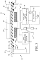
- Fig. 3 illustrates an embodiment in accordance with the invention which is similar to that illustrated in Fig. 1 , but including the improved antenna of the invention providing for substantially continuous RF communication between a heating apparatus 60 and a vessel 62, notwithstanding variations in the relative position of the vessel relative to the heating apparatus.
- the same reference numerals are used.
- the vessel 62 includes a heatable food-holding section 24 equipped with a centrally mounted temperature sensor 64, as well as handle 26 equipped with RFID tag 30 operably coupled with the sensor 64.
- the heating apparatus 60 includes support 32 as well as one or more hobs 34. Each hob has an induction work coil 36 and an associated inverter 38 and rectifier 40.
- the control circuitry 37 likewise includes microprocessor 42 and a RFID reader/writer 44 operably coupled with the antenna assembly 66 of the present invention. Again, a real-time clock 50 and added memory 52 are optionally coupled with microprocessor 42.
- the heating apparatus 60 and vessel 62 can be operated in the manner of apparatus 20 and vessel 22 as previously described, or in any desired fashion making use of RF communication between the tag 30, reader/writer 44, and microprocessor 42.
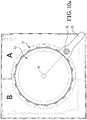
- the preferred antenna assembly 66 of the invention is best illustrated in Figs. 5-9 .
- This antenna assembly includes a multiple loop antenna broadly referred to by the numeral 67.
- the antenna 67 is supported on a non-conductive, plate-like synthetic resin substrate 68 (e.g., printed circuit board material such as FR4), and is in the form of a plurality (here two) continuous, conductive antenna loops 70, 72 respectively defining half antenna loops A and B ( Fig. 5 ).
- the half loop 70 is formed on the upper face of substrate 68, while the half loop 72 is formed on the opposed, lower face thereof.
- Each such half loop is formed by a pair of closely spaced, copper tracings 74, 76 and 78, 80, which may be applied in any conventional manner such as by etching, electroplating, or sputtering.
- the tracings 74, 76 of half loop 70 are each 1.59 mm (0.0625 inches) in width and are spaced apart a similar distance.
- each of the half loops 70, 72 include an arcuate inner section 82 and 84, as well as opposed, straight segments 86 and 88 extending outwardly from the respective sections 82 and 84, and generally straight C-sections 90 and 92 interconnecting the outboard ends of the segments 86 and 88.
- the inner sections 82 and 84, the segments 86 and 88, and the segments 90 and 92 define respective, enclosed RF communication regions 94 and 96 outboard of the inner arcuate sections 82 and 84.
- the half loops 70, 72 are oriented to cooperatively and substantially surround the hob 34.
- the adjacent ends of the half loops 70, 72 near the segments 86, 88 are overlapped, thereby defining a completely continuous RF communication zone outboard of and completely surrounding the hob 34.
- the arcuate sections 82 and 84 are located slightly outboard of the outer periphery of hob 34, so as to minimize noise in the antenna circuitry and undue heating of the antenna.
- the sections 82 and 84 are located to cooperatively create an inner antenna diameter about 12.7 mm (one-half inch) greater than the diameter of the hob.
- each of the antenna halves 70, 72 has a pair of terminals respectively referred to as signal and ground terminals 104, 106 extending from the traces 74, 76 and 78, 80. These terminals are connected to respective leads 108, 110 including an individual assembly 98 or 100.
- the assembly 98 is illustrated in Fig. 6 includes a first capacitor assembly 112, a resistor 114, and a second capacitor assembly 116.
- the assembly 112 preferably includes a variable capacitor 118, as well as two fixed capacitors 120, 122, all of the capacitors 118-122 being in parallel.
- the second capacitor assembly 116 likewise includes a variable capacitor 124 and a fixed parallel capacitor 126 coupled with signal lead 108.
- the preferable equivalent capacitance of first capacitor assembly 112 for operation with a RFID reader/writer operating at 13.56 MHz is 3.9 pico Farads, with at least 50V operating voltage rating.
- the preferable equivalent capacitance of second capacitor assembly 116 for operation with a RFID reader/writer operating at 13.56 MHz is 20 pico Farads, with at least 50V operating voltage rating.
- the preferable resistance value of resistor 114 for operation with a RFID reader/writer operating at 13.56MHz is somewhere in the range of a low of 0.47ohm to a high of open circuit, where the value of this resistor is directly proportional the Q-factor of the circuit.
- the signal and ground leads 108, 110 from the respective half loop antennas 70, 72 are operably coupled with network 102.
- This network includes a pair of signal and ground leads 128, 130 connected to reader/writer 44 via connector 132.
- the network 102 has a resistor 140, in series electrical connection with ground lead 130. The value of this resistor 140 determines the attenuation of the antenna circuit, where a zero ohm resistance provides no attenuation and a higher value of resistance 140 provides output power attenuation if necessary so as to prevent saturation of an RFID tag used with this antenna.
- any resistance value up to several Kohms may be employed to attenuate the output power of the connected reader.
- the maximum operating power of the resistor should reflect the output power of the reader being used with the antenna of this invention.
- the coaxial cable from the reader/writer 44 should pass through the center of a ferrite toroid two to four times (forming two to four loops of wire around the toroid) enroute to the connector 132 so as to act as a common mode choke to help the overall performance of the RFID system (see, Constructing A 1000 x 600 HF Antenna Technical Application Report, Lit. Number 11-08-26-007, Texas Instruments, 2003 .)
- the ferrite toroid acts as an impedance matching component that balances the RF lines between the antenna assembly 66, the reader/writer 44, and the coaxial cable itself and reduces "reading holes" in the antenna's field area.
- a ferrite toroid with part number 5943000301 from the Fair-Rite Corporation has proven itself optimum in this application.
- the antenna assembly 66 of the invention permits continuous RF communication between RFID tag 30 and reader/writer 44 notwithstanding the angular position of the vessel handle 26.
- Fig. 9 illustrates this operational feature,
- an induction hob 34 is depicted and the electromagnetic flux therefrom is illustrated with "- +-" hatching.
- the surrounding RF communication zone cooperatively defined by the half loops 70, 72 is illustrated in diagonal stairstep hatching.
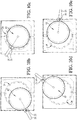
- Fig. 10a illustrates the placement of vessel 62 on an induction hob 34, with the handle 26 located at approximately a 4 o'clock position. As illustrated, this vessel orientation establishes RF communication between the tag 30 and reader/writer 44, Figs. 10b through 10e illustrate other pan/heating apparatus relative orientations which still maintain such RF communication. Thus, the vessel 62 can be displaced radially relative to the hob 34 over relatively large distances without breaking the RF communication. Generally, so long as approximately one half of the effective communication area presented by RFID tag 30 is above the RF communication regions 94 and 96 established by antenna assembly 66, RF communication will be maintained.
- the invention has been described in the context of induction heating hobs and cooking vessels such as pans or pots, However, the invention is not so limited.
- the antenna of the invention may also be used in connection with other types of cooking/warming hobs, e.g., gas, radiant, electric resistive, or halogen hobs.
- the antenna can be used with other types of inductively coupled RF reader/transponder systems.
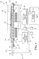
- Fig. 4 illustrates a heating apparatus 60 identical to that depicted to that in Fig. 3 (and thus identical reference numerals are used throughout) in conjunction with another type of vessel assembly 146.
- the assembly 146 includes a trivet 148 equipped with a peripheral RFID tag 150 and a central temperature sensor 152 operably coupled with the tag 150.
- a conventional vessel 154 such as a pan or skillet, is positioned atop trivet 148 such that the sensor 152 may continuously monitor the temperature of the vessel.
- the RF communication between tag 150 and reader/writer 44 serves to control the heating of the vessel 152 via temperature feedback from the sensor 152 attached to the removable trivet 148 but still associated with the vessel 152.
- This illustrates that the invention can be used for establishing RF communication when heating virtually any type of object equipped with a peripheral RFID tag or the like.
Description
- The present invention is broadly concerned with improved RF antenna assemblies used as a part of an induction or other type of heating apparatus in order to establish and maintain RF communication between the heating apparatus and an object being heated having a peripheral-mounted RF transponder. More particularly, it is concerned with such antenna assemblies, as well as overall heating systems and combinations thereof including heatable objects, making use of the improved RF antenna assemblies. The preferred RF antenna assemblies comprise multiple antenna loops cooperatively defining a substantially continuous RF communication zone outboard of a cooking hob.
- Several prior art induction heating systems have been developed which use RF communications between a transmitter/receiver forming a part of the induction heater, and a radio frequency transponder (e.g., a RFID tag) associated with the object to be heated by the induction heater, Such RF communications include transponder feedback that is use by the induction heater to alter and/or control the heating of the object. The transmitter/receivers of such systems also include an antenna designed to interrogate the transponder and to receive information therefrom. The position of the antenna relative to the work coil of the induction heater in these systems is important in establishing and maintaining the necessary RF communication, and in allowing the user some freedom of placement of the object while it is being heated.
- For example,
U.S. Patent No. 6,320,169 describes an induction heating system having a RFID antenna located at the center of the cooking hob, i.e., in the center of the heater's work coil. In this type of system the object being heated can have a RFID tag affixed to the object's symmetry position, typically in the geometric center of the object. This symmetry position for both the RFID antenna and the RFID tag allows use of standard RFID antennas typically constructed of planar spiral or other geometric shape traces printed on a rigid substrate, with associated on-board capacitor(s) and other electronic components. This symmetry orientation allows the object to be heated to be rotated through a full 360E angular orientation while atop the hob, without loss of RFID communication. - However, many heatable objects are designed to be heated to a temperature by a cooking/warning hob that exceeds the maximum operating temperature range of the RFID tag (usually 85 °C, and sometimes 125 °C for microchip-based RFID tags, or possibly even higher for chipless RFID tags, resonant tag labels, planar LC resonators, printed RFID tags, or other chipless sensors such as the SENS-10, each sold by TagSense, Inc. of Cambridge, MA). Hence, it is often impractical to place the RFID tag or other transponder in a heatable portion of the object such as the center symmetry position. This is especially true in connection with cooking vessels or utensils, which are commonly subjected to very high heating temperatures.
- One response to this problem is to mount the transponder or RFID tag on the periphery of an object subj ected to high heating/warming temperatures, thereby reducing the heat load on the transponder or tag. The first known attempt to use a periphery-mounted RFID tag on a cooking vessel is described in
U.S. Patent No. 6,953,919 . This patent discloses the use of a RFID tag preferentially located in the vessel's handle, remote from the heatable portion of the vessel, and thus allowing the tag to operate and survive at the ambient or slightly elevated temperatures of the vessel handle. However, this patent teaches that the RFID reader antenna can only maintain RF communication with the handle-mounted RFID tag through a limited angular rotation of the vessel. Indeed, this patent discloses that the RFID reader antenna preferably covers only a quadrant of the periphery of the work coil. Consequently, where the RFID tag is handle-mounted, the vessel must be maintained in a relatively small range of angular positions, else the necessary RF communication between the tag and reader will be lost. This presents a significant problem to the user, i.e., casual or even professional users may accidentally move the vessel handle out of the range of the RFID antenna during food preparation. Moreover, many users wish to place vessel handles in various different orientations for ease of food preparation or to ensure that a given handle is not inadvertently contacted, resulting in spillage. - Thus, designers of warming/cooking devices such as induction cooktops have recognized that the ability to allow a user to have the freedom to rotate vessel handles through a wide angular range during heating/cooking is an important feature. Attempts have been made to address this problem in several published patent applications. For instance, Japanese Publication No.
2006-344453 - Japanese Publication No.
2006-294372 - No known prior art describes any structure or means which provides a RF antenna forming a part of a heating device for use with cookware, servingware, or other heatable objects equipped with peripheral-mounted RF transponders, wherein the object being heated can be rotated through substantially 360° and/or radially displaced without loss of RF communication between the transponder and heating device. Accordingly, there is a real and unsatisfied need in the art for an improved antenna useful with a variety of heating devices and which establishes a substantially continuous RF communication zone outboard of and substantially surrounding the hob(s) of the heating device, thereby allowing a user to rotate an object being heated having a peripheral RF transponder to virtually any desired angular position without communication loss.
-
EP 1 229 482 A2 discloses a reader coil antenna for a non-contact type card reader. This coil comprises an outer coil and an inner coil disposed inside the outer coil. The coils are connected in series. -
US 6 953 919 B2 describes a system and a method for providing multiple cooking modes and an ability to automatically heat (by means of induction heating) cooking vessels and other objects using RFID technology. - The present invention relates to an RF antenna assembly and to an induction heating system and is defined in claim 1 and in
claim 8, respectively. Advantageous versions of the invention follow from the dependent claims. - The present invention overcomes the problems outlined above and provides an RF antenna assembly normally forming a part of a heating apparatus including one or more heating hobs designed to heat an object. The antenna assembly is operable to communicate with an associated RF device peripherally coupled with the object, such as an RFID tag. Such RF communication is maintained even when the object is located at a variety of rotated or displaced positions relative to the heating hob through substantially 360° about the hob.
- The preferred antenna assembly of the invention broadly includes an antenna including a plurality of continuous, conductive antenna loops oriented to cooperatively and substantially surround the heating hob, with each of the loops having an inner section proximal to said hob and defining a respective, enclosed RF communication region outboard of the inner loop section, Such zones cooperatively define a substantially continuous RF communication zone outboard of and disposed about the hob. The antenna assembly also has circuitry including at least two conductive paths adapted for coupling with a signal generator, wherein the plurality of loops each has one terminal end connected to at least one of the conductive paths, and having a second terminal end connected to at least one other of the conductive paths.
- In particularly preferred embodiments, adjacent ends of the antenna loops are overlapped to cooperatively define a continuous RF communication zone outboard of and surrounding the hob. The plural, overlapped antenna loops ensure that there are no RF communication "dead zones" about the entire periphery of the hob. The antenna loops are not in electrical series, but are rather each connected to a signal generator such as a RFID reader or reader/writer. For ease of manufacture, the antenna assembly is mounted on a substrate supporting the antenna loops and associated circuitry. The substrate presents a pair of opposed faces, with at least one of the antenna loops on one of the faces, and another of the loops on the other of the faces. Alternately, all of the loops can be applied to one face of the substrate, so long as appropriate electrical connections are maintained with no series connections between the antenna loops. The antenna loops are advantageously formed as a pair of closely spaced apart, parallel copper traces. Tuning assemblies are also coupled with the loops in order to tune each of the antenna loops with reference to the signal generator's driving frequency,
- The antenna of the invention finds particular utility in induction heating systems for various objects including a component such as a heating hob for generating a magnetic field in order to inductively heat an object, with control circuitry operably coupled with the field-generating component in order to control the operation of the latter. Such control circuitry includes an RFID tag reader (or more preferably a RFID reader/writer) and the antenna of the invention coupled with the tag reader in order to interrogate a proximal RFID tag associated with the object being heated, and to receive information from the object-mounted (or object-associated) RFID tag. The antenna of this invention is especially advantageous for use with induction hobs because each of its plurality of loops provides very little penetration area for magnetic field lines emanating from the induction hob. Thus, each of the plurality of antenna loops experiences very little induced voltage (noise) due to time-changing flux from the hob's alternating magnetic field, and thus the signal-to-noise ratio of each of the plurality of antennas can be very high. This lack of induced noise is a great advantage over a single loop antenna configured to fully surround the induction hob, which experiences severe induced noise.
-
-
Figure 1 is a schematic side view partially in section of a prior art induction heating system as described inU.S. Patent No. 6,953,919 , illustrating a cooking vessel equipped with a peripheral, handle-mounted RFID tag, with the vessel resting atop a magnetic induction cooker in an effective cooking position wherein the vessel RFID tag is properly positioned for RF communication with a conventional quadrant-type RFID antenna forming a part of the induction cooker; -
Fig. 2 is a plan view of the prior art heating system illustrated inFig. 1 ; -
Fig. 3 is a schematic side view partially in section of an induction heating system in accordance with the invention, wherein the induction cooker is equipped with the improved RFID antenna hereof; -
Fig. 4 is a schematic side view partially in section of an induction heating system wherein an intermediate trivet is positioned between the upper surface of the induction cooker and a pan to be heated, wherein the trivet is equipped with a temperature sensor and RFID tag and the induction cooker includes the improved antenna of the invention; -
Fig. 5 is a plan view of a preferred RF antenna in accordance with the invention and illustrating an antenna-supporting substrate and the positioning of the side A and B half antenna traces on opposite sides of the substrate; -
Fig. 6 is an enlarged view of the portions of the antenna circuitry schematically depicted inFig. 5 asboxes 6; -
Fig. 7 is an enlarged view of the portion of the antenna circuitry schematically depicted inFig. 5 asbox 7; -
Fig. 8 is an enlarged, fragmentary view of the antenna traces schematically illustrated inFig. 5 asbox 8; -
Fig. 9 is a plan view similar to that ofFig. 5 , but illustrating the magnetic flux lines of an induction cooking work coil surrounded by the antenna of the invention, and also the RF communication zone outboard of the work coil established by the improved antenna of the invention; -
Fig. 10a is a plan view illustrating placement of a pan having a central temperature detector and handle-mounted RFID tag located centrally on the cooking hob of an induction cooker and further illustrating the position of the antenna hereof relative to the hob and pan; -
Fig. 10b is a view similar to that ofFig. 10a , but illustrating the pan in a radially displaced orientation relative to the cooking hob, while nonetheless maintaining RF communication between the handle-mounted RFID tag and the antenna; -
Fig. 10c is a view similar to that ofFig. 10a , but illustrating another offset pan orientation which still maintains RF communication between the handle-mounted RFID tag and the antenna; -
Fig. 10d is a view similar to that ofFig. 10a , but illustrating another offset pan orientation which still maintains RF communication between the handle-mounted RFID tag and the antenna; and -
Fig. 10e is a view similar to that ofFig. 10a , but illustrating another offset pan orientation which still maintains RF communication between the handle-mounted RFID tag and the antenna. - Referring first to
Figs. 1 and2 , a prior artinduction heating apparatus 20 and associatedheatable cooking vessel 22 are illustrated. This apparatus is of the type described inU.S. Patent No. 6,953,919 . - In general, these Figures depict an exemplary RFID-equipped
cooking vessel 22 in the form of a pan or skillet having a food-holdingsection 24 andelongated handle 26. Thehandle 26 includes a resistanttemperature sensing device 28 in thermal connection with thesection 24, and an electrically coupledRFID tag 30. - The
heating apparatus 20 includes anupper support 32 adapted to supportvessel 22 as shown. Theapparatus 20 also includes one ormore hobs 34 having awork coil 36 and associatedultrasonic frequency inverter 38 andrectifier 40. As illustrated, thevessel 22 is positioned directly above thehob 34 andwork coil 36. Theoverall control circuitry 37 associated with theapparatus 20 includes amicroprocessor 42, a RFID reader/writer 44, and one ormore RFID antennas time clock 50 andadditional memory 52 are coupled with themicroprocessor 42. In the illustrated embodiment, thecontrol circuitry 37 also includes auser interface 54,display 56, andinput device 58. - It will be seen that
vessel 22 is located centrally within the confines ofhob 34 andwork coil 36, withantenna 48 located in a corner region at approximately a 7 o'clock position beneath thesupport 32 ofheating apparatus 20. However, owing to the peripheral location of theRFID tag 30, only the corner-mountedantenna 48 comes into play in the illustrated embodiment and provides inductive coupling and RF communication between thevessel 22 andheating apparatus 20. This in turn means that such RF communication can only occur when thehandle 26 is positioned at approximately a 7 o'clock position directly above theantenna 48, as best illustrated in full lines inFig. 2 . On the other hand, if thevessel 22 is rotated or otherwise displaced so that thehandle 26 is no longer above and within the range of theantenna 48, the necessary RF communication between thevessel 22 andapparatus 20 is lost. This is illustrated inFig. 2 in phantom, where it will be seen thatvessel 22 is rotated such that handle 26 is in approximately a 4 o'clock position, outside of the range ofantenna 48. Indeed, it has been found that using typical RFID antennas in the shape of circles, ovals, or parallelograms, RF communication between thevessel 22 andapparatus 20 can only be maintained through about 45E of the full 360° abouthob 34. - The
apparatus 20 andvessel 22 are in RF communication for information exchange between themicroprocessor 42 andRFID tag 30, when thehandle 26 is substantially above the corner-mountedantenna 48. In such an orientation, theheating apparatus 20 can be controlled over a sequence of predetermined heating steps. In one particularly preferred embodiment, theheating apparatus 20 is designed to read a set of heating instructions from an external storage medium, and such instructions are used in conjunction with vessel temperature information received fromRFID tag 30 during the course of vessel heating, to control the heating sequence for a particular food or recipe. Additionally, thedisplay 56 may prompt a user to add specific ingredients to thevessel 22 to take other steps such as stirring during the course of food preparation. Of course, the RFID tag may also transmit other information such as vessel identification and vessel heating history. -
Fig. 3 illustrates an embodiment in accordance with the invention which is similar to that illustrated inFig. 1 , but including the improved antenna of the invention providing for substantially continuous RF communication between aheating apparatus 60 and avessel 62, notwithstanding variations in the relative position of the vessel relative to the heating apparatus. In order to simplify the description of this embodiment, where components identical to those present in theFig. 1 embodiment are employed, the same reference numerals are used. - Thus, the
vessel 62 includes a heatable food-holdingsection 24 equipped with a centrally mountedtemperature sensor 64, as well as handle 26 equipped withRFID tag 30 operably coupled with thesensor 64. Theheating apparatus 60 includessupport 32 as well as one ormore hobs 34. Each hob has aninduction work coil 36 and an associatedinverter 38 andrectifier 40. Thecontrol circuitry 37 likewise includesmicroprocessor 42 and a RFID reader/writer 44 operably coupled with theantenna assembly 66 of the present invention. Again, a real-time clock 50 and addedmemory 52 are optionally coupled withmicroprocessor 42. Theheating apparatus 60 andvessel 62 can be operated in the manner ofapparatus 20 andvessel 22 as previously described, or in any desired fashion making use of RF communication between thetag 30, reader/writer 44, andmicroprocessor 42. - The
preferred antenna assembly 66 of the invention is best illustrated inFigs. 5-9 . This antenna assembly includes a multiple loop antenna broadly referred to by the numeral 67. Theantenna 67 is supported on a non-conductive, plate-like synthetic resin substrate 68 (e.g., printed circuit board material such as FR4), and is in the form of a plurality (here two) continuous,conductive antenna loops Fig. 5 ). In this design thehalf loop 70 is formed on the upper face ofsubstrate 68, while thehalf loop 72 is formed on the opposed, lower face thereof. Each such half loop is formed by a pair of closely spaced,copper tracings Fig. 8 , thetracings half loop 70 are each
1.59 mm (0.0625 inches) in width and are spaced apart a
similar distance, It will also be seen that each of thehalf loops inner section straight segments respective sections sections segments inner sections segments segments RF communication regions arcuate sections half loops hob 34. In the illustrated embodiment, the adjacent ends of thehalf loops segments hob 34. Preferably, thearcuate sections hob 34, so as to minimize noise in the antenna circuitry and undue heating of the antenna. Normally, thesections - The connection of
half loops writer 44 is preferably effected through the use ofantenna circuitry 97 including a pair ofidentical tuning assemblies terminal network 102. Specifically, each of the antenna halves 70, 72 has a pair of terminals respectively referred to as signal andground terminals traces respective leads individual assembly assembly 98 is illustrated inFig. 6 includes afirst capacitor assembly 112, aresistor 114, and asecond capacitor assembly 116. Theassembly 112 preferably includes avariable capacitor 118, as well as two fixedcapacitors second capacitor assembly 116 likewise includes avariable capacitor 124 and a fixedparallel capacitor 126 coupled withsignal lead 108. The preferable equivalent capacitance offirst capacitor assembly 112 for operation with a RFID reader/writer operating at 13.56 MHz is 3.9 pico Farads, with at least 50V operating voltage rating. The preferable equivalent capacitance ofsecond capacitor assembly 116 for operation with a RFID reader/writer operating at 13.56 MHz is 20 pico Farads, with at least 50V operating voltage rating. The preferable resistance value ofresistor 114 for operation with a RFID reader/writer operating at 13.56MHz is somewhere in the range of a low of 0.47ohm to a high of open circuit, where the value of this resistor is directly proportional the Q-factor of the circuit. The higher theresistor value 114, the higher the Q-factor of the respective half loop antenna. This high Q-factor can be beneficial for long read range capability. Although current models of the antenna of this invention use noresistor 114 on the circuit, thus givingresistor 114 an open circuit value and hence a maximum Q-factor, asmaller resistance value 114 can be used to lower the Q-factor to allow for less read range at ideal temperature conditions but more effective operation of the antenna of this invention in variable temperature environments where the variable temperature of the antenna circuit components can vary their effective values and thus the tuning of the antenna, thereby making a lower Q-factor antenna more capable of effective operation over a wide range of operating temperatures than an antenna with a high Q-factor. - The signal and ground leads 108, 110 from the respective
half loop antennas 70, 72 (or sides A and B) are operably coupled withnetwork 102. This network includes a pair of signal and ground leads 128, 130 connected to reader/writer 44 viaconnector 132. Thenetwork 102 has a resistor 140, in series electrical connection withground lead 130. The value of this resistor 140 determines the attenuation of the antenna circuit, where a zero ohm resistance provides no attenuation and a higher value of resistance 140 provides output power attenuation if necessary so as to prevent saturation of an RFID tag used with this antenna. Although current models of the antenna of this invention use a zero ohm, ¼watt resistor 114, any resistance value up to several Kohms may be employed to attenuate the output power of the connected reader. The maximum operating power of the resistor should reflect the output power of the reader being used with the antenna of this invention. When connectingantenna assembly 66 of this invention to the reader/writer 44 viaconnector 132, it has been found that the coaxial cable from the reader/writer 44 should pass through the center of a ferrite toroid two to four times (forming two to four loops of wire around the toroid) enroute to theconnector 132 so as to act as a common mode choke to help the overall performance of the RFID system (see, Constructing A 1000 x 600 HF Antenna Technical Application Report, Lit. Number 11-08-26-007, Texas Instruments, 2003.) The ferrite toroid acts as an impedance matching component that balances the RF lines between theantenna assembly 66, the reader/writer 44, and the coaxial cable itself and reduces "reading holes" in the antenna's field area. A ferrite toroid with part number 5943000301 from the Fair-Rite Corporation has proven itself optimum in this application. - As indicated in
Figures 3 and5 , theantenna assembly 66 of the invention permits continuous RF communication betweenRFID tag 30 and reader/writer 44 notwithstanding the angular position of thevessel handle 26.Fig. 9 illustrates this operational feature, Thus, inFig. 9 , aninduction hob 34 is depicted and the electromagnetic flux therefrom is illustrated with "- +-" hatching. Also, the surrounding RF communication zone cooperatively defined by thehalf loops RFID tag 30 carried byhandle 26 is substantially above this RF communication zone, effective communication between thetag 30 and reader/writer 44 is maintained. At the same time, there is a relatively high signal to noise ratio with theantenna assembly 66, -
Fig. 10a illustrates the placement ofvessel 62 on aninduction hob 34, with thehandle 26 located at approximately a 4 o'clock position. As illustrated, this vessel orientation establishes RF communication between thetag 30 and reader/writer 44,Figs. 10b through 10e illustrate other pan/heating apparatus relative orientations which still maintain such RF communication. Thus, thevessel 62 can be displaced radially relative to thehob 34 over relatively large distances without breaking the RF communication. Generally, so long as approximately one half of the effective communication area presented byRFID tag 30 is above theRF communication regions antenna assembly 66, RF communication will be maintained. - In the foregoing discussion, the invention has been described in the context of induction heating hobs and cooking vessels such as pans or pots, However, the invention is not so limited. For example, the antenna of the invention may also be used in connection with other types of cooking/warming hobs, e.g., gas, radiant, electric resistive, or halogen hobs. Further, the antenna can be used with other types of inductively coupled RF reader/transponder systems.
-
Fig. 4 illustrates aheating apparatus 60 identical to that depicted to that inFig. 3 (and thus identical reference numerals are used throughout) in conjunction with another type ofvessel assembly 146. Theassembly 146 includes atrivet 148 equipped with aperipheral RFID tag 150 and acentral temperature sensor 152 operably coupled with thetag 150. Aconventional vessel 154, such as a pan or skillet, is positioned atoptrivet 148 such that thesensor 152 may continuously monitor the temperature of the vessel. In this system, the RF communication betweentag 150 and reader/writer 44 serves to control the heating of thevessel 152 via temperature feedback from thesensor 152 attached to theremovable trivet 148 but still associated with thevessel 152. This illustrates that the invention can be used for establishing RF communication when heating virtually any type of object equipped with a peripheral RFID tag or the like.
Claims (9)
- An RF antenna assembly (66) operable to communicate with an associated RF device located at various positions about a heating hob disposed in an inner area, said antenna assembly comprising an antenna (67) including a plurality of continuous, conductive antenna loops (70, 72) located about the inner area, and circuitry (97), characterized in that:said antenna loops (70, 72) are oriented to cooperatively surround said inner area,each of said loops (70, 72) having an inner section (82, 84) proximal to said inner area and defining a respective, enclosed RF communication region (94, 96) outboard of said inner loop section (82, 84) with respect to said inner area,said regions (94, 96) cooperatively defining a continuous RF communication zone outboard of and disposed about the inner area;said circuitry (97) includes at least two conductive paths adapted for coupling with a signal generator, andsaid plurality of loops (70, 72) each having one terminal end (104) connected to at least one of said conductive paths, and having a second terminal end (106) connected to at least one other of said conductive paths, whereby said antenna loops (70, 72) are not connected in series.
- The antenna assembly of claim 1, adjacent ends of said loops (70, 72) being overlapped to cooperatively define said continuous RF communication zone.
- The antenna assembly of claim 1, including a substrate (68) supporting said antenna loops (70, 72) and presenting a pair of opposed faces, at least one of said antenna loops (70) on one of said faces, and another of said loops (72) on the other of said faces.
- The antenna assembly of claim 1, there being a pair of said antenna loops (70, 72).
- The antenna assembly of claim 1, said loops (70, 72) each formed of a pair of spaced apart, parallel copper traces (74, 76, 78, 80).
- The antenna assembly of claim 1, one of said conductive paths being a signal input path from a signal generator, and another of said paths being a ground path.
- The antenna assembly of claim 1, including a bandpass frequency tuning filter operably coupled to said two conductive paths, said filter including a network of inductors and adjustable capacitors.
- An induction heating system (20) comprising:a component (36) for generating a magnetic field in order to inductively heat an object, said component (36) presenting a heating hob (34);an antenna assembly (66) comprising an antenna (67); andcontrol circuitry (37) operably coupled with said field-generating component (36) in order to control the operation of the component (36), including an RFID tag reader (44) and the antenna (67) of said antenna assembly (66), which antenna (67) is coupled with the tag reader (44) in order to interrogate a proximal RFID tag (30) associated with said object, and to receive information from said RFID tag (30),characterized in that said antenna assembly (66) is an antenna assembly (66) according to any of the previous claims,wherein said heating hob (34) is disposed in the inner area, andwherein the at least two conductive paths are coupled with said RFID tag reader (44), and wherein said plurality of loops (70, 72) each have one terminal end (104) connected to at least one of said conductive paths, and have a second terminal end (106) connected to at least one other of said conductive paths in order to operably couple the RFID tag reader (44) with said antenna (67).
- The induction heating system of claim 8, said component comprising an induction work coil (36).
Applications Claiming Priority (2)
| Application Number | Priority Date | Filing Date | Title |
|---|---|---|---|
| US12/027,185 US8350196B2 (en) | 2008-02-06 | 2008-02-06 | Radio frequency antenna for heating devices |
| PCT/US2008/053470 WO2009099445A1 (en) | 2008-02-06 | 2008-02-08 | Radio frequency antenna for heating devices |
Publications (3)
| Publication Number | Publication Date |
|---|---|
| EP2241162A1 EP2241162A1 (en) | 2010-10-20 |
| EP2241162A4 EP2241162A4 (en) | 2014-11-26 |
| EP2241162B1 true EP2241162B1 (en) | 2020-04-22 |
Family
ID=40930654
Family Applications (1)
| Application Number | Title | Priority Date | Filing Date |
|---|---|---|---|
| EP08729434.4A Active EP2241162B1 (en) | 2008-02-06 | 2008-02-08 | Radio frequency antenna for heating devices |
Country Status (5)
| Country | Link |
|---|---|
| US (1) | US8350196B2 (en) |
| EP (1) | EP2241162B1 (en) |
| JP (1) | JP5351179B2 (en) |
| CN (1) | CN101965750B (en) |
| WO (1) | WO2009099445A1 (en) |
Families Citing this family (38)
| Publication number | Priority date | Publication date | Assignee | Title |
|---|---|---|---|---|
| US7385357B2 (en) | 1999-06-21 | 2008-06-10 | Access Business Group International Llc | Inductively coupled ballast circuit |
| US9955529B2 (en) | 2009-01-06 | 2018-04-24 | Access Business Group International Llc | Smart cookware |
| US8931400B1 (en) | 2009-05-28 | 2015-01-13 | iDevices. LLC | Remote cooking systems and methods |
| CN102511198B (en) * | 2009-12-09 | 2013-10-30 | 松下电器产业株式会社 | High frequency heating device, and high frequency heating method |
| ES2367281B1 (en) * | 2010-03-16 | 2012-09-04 | Electrodomésticos Taurus S.L. | KITCHEN HOBBY WITH OPERATING MEANS FOR ROTATING BLADES AND KITCHEN HOB ASSEMBLY AND KITCHEN CONTAINER WITH ROTATING BLADES. |
| CN103109165B (en) | 2010-04-08 | 2015-08-19 | 捷通国际有限公司 | Point of sale induction system and method |
| US8754351B2 (en) | 2010-11-30 | 2014-06-17 | Bose Corporation | Induction cooking |
| ES2393378B1 (en) * | 2011-06-07 | 2013-10-31 | Electrodomésticos Taurus, S.L. | KITCHEN BASKET WITH ROTATING DRIVING MEDIA AND KITCHEN CONTAINER USED WITH SIDE UP |
| DE102011088918A1 (en) * | 2011-12-16 | 2013-06-20 | E.G.O. Elektro-Gerätebau GmbH | Method of transmitting data, induction heating device, inductively heated cooking vessel and system |
| WO2014068647A1 (en) * | 2012-10-30 | 2014-05-08 | 三菱電機株式会社 | Induction heating cooker |
| WO2014169149A1 (en) * | 2013-04-10 | 2014-10-16 | Pentair Thermal Management Llc | Heating cable having an rfid device |
| CN104112912A (en) * | 2013-04-18 | 2014-10-22 | 航天信息股份有限公司 | Parameter adjustment method for high-frequency reader-writer antenna applied in metal environment |
| CN104427671B (en) * | 2013-09-10 | 2017-11-10 | 美的集团股份有限公司 | Electromagnetic heater, cooking equipment and its control method |
| US9470423B2 (en) | 2013-12-02 | 2016-10-18 | Bose Corporation | Cooktop power control system |
| ES2618810B1 (en) * | 2015-12-17 | 2018-04-06 | Bsh Electrodomésticos España, S.A. | Underlying device intended to be disposed between a cooking battery and a cooking field |
| ES2648713B1 (en) * | 2016-07-04 | 2018-10-17 | Copreci, S.Coop. | Temperature measuring device, cooking device and cooking system |
| US11109451B2 (en) * | 2016-07-20 | 2021-08-31 | Kymeta Corporation | Internal heater for RF apertures |
| EP3280224A1 (en) | 2016-08-05 | 2018-02-07 | NXP USA, Inc. | Apparatus and methods for detecting defrosting operation completion |
| EP3280225B1 (en) | 2016-08-05 | 2020-10-07 | NXP USA, Inc. | Defrosting apparatus with lumped inductive matching network and methods of operation thereof |
| US10093218B2 (en) * | 2016-11-15 | 2018-10-09 | Bauer Compressors, Inc. | Tank support system incorporating tank identification |
| US10120553B1 (en) | 2017-04-17 | 2018-11-06 | Sebastian Thrun | User interface and controller for a heating system |
| US10101035B1 (en) | 2017-04-17 | 2018-10-16 | Silicon Valley Factory LLC | Custom cooking program based on feedback |
| US10061285B1 (en) | 2017-04-17 | 2018-08-28 | Silicon Valley Factory LLC | Encoding a custom cooking program |
| US10009963B1 (en) | 2017-04-17 | 2018-06-26 | Silicon Valley Factory LLC | Decoding a custom cooking program |
| US10070485B1 (en) | 2017-04-17 | 2018-09-04 | Silicon Valley Factory LLC | Automatic heating system and method |
| JP6998152B2 (en) * | 2017-08-29 | 2022-01-18 | リンナイ株式会社 | Stove |
| KR102355669B1 (en) * | 2017-09-29 | 2022-01-25 | 엘지전자 주식회사 | Support structure for the object to be heated |
| US10917948B2 (en) | 2017-11-07 | 2021-02-09 | Nxp Usa, Inc. | Apparatus and methods for defrosting operations in an RF heating system |
| US10771036B2 (en) | 2017-11-17 | 2020-09-08 | Nxp Usa, Inc. | RF heating system with phase detection for impedance network tuning |
| EP3503679B1 (en) | 2017-12-20 | 2022-07-20 | NXP USA, Inc. | Defrosting apparatus and methods of operation thereof |
| CA3087324A1 (en) * | 2017-12-29 | 2019-07-04 | Breton Spa | Countertop with induction hob |
| BR112020013261A2 (en) * | 2017-12-29 | 2020-12-01 | Avery Dennison Retail Information Services, Llc | active rfid temperature media with dual passive technology |
| US11606845B2 (en) * | 2018-03-22 | 2023-03-14 | Illinois Tool Works Inc. | Induction heating systems having close proximity communication devices |
| EP3547801B1 (en) | 2018-03-29 | 2022-06-08 | NXP USA, Inc. | Defrosting apparatus and methods of operation thereof |
| US10952289B2 (en) | 2018-09-10 | 2021-03-16 | Nxp Usa, Inc. | Defrosting apparatus with mass estimation and methods of operation thereof |
| US11800608B2 (en) | 2018-09-14 | 2023-10-24 | Nxp Usa, Inc. | Defrosting apparatus with arc detection and methods of operation thereof |
| US11166352B2 (en) | 2018-12-19 | 2021-11-02 | Nxp Usa, Inc. | Method for performing a defrosting operation using a defrosting apparatus |
| US11039511B2 (en) | 2018-12-21 | 2021-06-15 | Nxp Usa, Inc. | Defrosting apparatus with two-factor mass estimation and methods of operation thereof |
Family Cites Families (20)
| Publication number | Priority date | Publication date | Assignee | Title |
|---|---|---|---|---|
| EP0704928A3 (en) * | 1994-09-30 | 1998-08-05 | HID Corporation | RF transponder system with parallel resonant interrogation and series resonant response |
| US6320169B1 (en) | 1999-09-07 | 2001-11-20 | Thermal Solutions, Inc. | Method and apparatus for magnetic induction heating using radio frequency identification of object to be heated |
| KR100746742B1 (en) | 2001-02-03 | 2007-08-06 | 삼성전자주식회사 | Reader coil antenna and non-contacting type card identification system using the same |
| JP2002359511A (en) | 2001-06-01 | 2002-12-13 | Hitachi Maxell Ltd | Communication device |
| JP2003242451A (en) | 2002-02-19 | 2003-08-29 | Tamura Electric Works Ltd | Non-contact ic card reader/writer |
| JP3975918B2 (en) * | 2002-09-27 | 2007-09-12 | ソニー株式会社 | Antenna device |
| US6861993B2 (en) * | 2002-11-25 | 2005-03-01 | 3M Innovative Properties Company | Multi-loop antenna for radio-frequency identification |
| US6953919B2 (en) * | 2003-01-30 | 2005-10-11 | Thermal Solutions, Inc. | RFID-controlled smart range and method of cooking and heating |
| JP2004364199A (en) | 2003-06-06 | 2004-12-24 | Sony Corp | Antenna module and portable communication terminal equipped therewith |
| US7417599B2 (en) * | 2004-02-20 | 2008-08-26 | 3M Innovative Properties Company | Multi-loop antenna for radio frequency identification (RFID) communication |
| US7157675B2 (en) | 2004-04-28 | 2007-01-02 | Imura International U.S.A. Inc. | Radio frequency identification controlled heatable objects |
| US7432874B2 (en) * | 2004-07-22 | 2008-10-07 | Feig Electronic Gmbh | Antenna array |
| US7158033B2 (en) * | 2004-09-01 | 2007-01-02 | Avery Dennison Corporation | RFID device with combined reactive coupler |
| JP4654740B2 (en) | 2005-04-08 | 2011-03-23 | パナソニック株式会社 | Cooker |
| JP2007013120A (en) * | 2005-05-30 | 2007-01-18 | Semiconductor Energy Lab Co Ltd | Semiconductor device |
| JP4810889B2 (en) | 2005-06-08 | 2011-11-09 | パナソニック株式会社 | Cooker |
| JP4848741B2 (en) | 2005-11-14 | 2011-12-28 | パナソニック株式会社 | Induction heating cooker |
| US7439860B2 (en) * | 2006-03-22 | 2008-10-21 | Assa Abloy Ab | Auto-tuned RFID reader antenna |
| US7806333B1 (en) * | 2006-03-27 | 2010-10-05 | Hewlett-Packard Development Company, L.P. | Tracking RFID tags with overlapping antennas |
| US7973730B2 (en) * | 2006-12-29 | 2011-07-05 | Broadcom Corporation | Adjustable integrated circuit antenna structure |
-
2008
- 2008-02-06 US US12/027,185 patent/US8350196B2/en active Active
- 2008-02-08 CN CN2008801279382A patent/CN101965750B/en active Active
- 2008-02-08 JP JP2010545843A patent/JP5351179B2/en active Active
- 2008-02-08 WO PCT/US2008/053470 patent/WO2009099445A1/en active Application Filing
- 2008-02-08 EP EP08729434.4A patent/EP2241162B1/en active Active
Non-Patent Citations (1)
| Title |
|---|
| None * |
Also Published As
| Publication number | Publication date |
|---|---|
| CN101965750A (en) | 2011-02-02 |
| US8350196B2 (en) | 2013-01-08 |
| EP2241162A1 (en) | 2010-10-20 |
| CN101965750B (en) | 2013-06-26 |
| JP5351179B2 (en) | 2013-11-27 |
| JP2011514623A (en) | 2011-05-06 |
| WO2009099445A1 (en) | 2009-08-13 |
| EP2241162A4 (en) | 2014-11-26 |
| US20090194526A1 (en) | 2009-08-06 |
Similar Documents
| Publication | Publication Date | Title |
|---|---|---|
| EP2241162B1 (en) | Radio frequency antenna for heating devices | |
| JP7457736B2 (en) | RFID tags that operate in high frequency bands | |
| AU756531B2 (en) | Rotating field antenna with a magnetically coupled quadrature loop | |
| EP2373201B1 (en) | Induction cookware identifying | |
| JP2011514623A5 (en) | ||
| US11212879B2 (en) | Temperature measurement system employing an electromagnetic transponder and separate impedance-changing parasitic antenna | |
| JP6328572B2 (en) | Induction heating cooker with non-contact power feeding function and control method thereof | |
| WO1994016471A1 (en) | Transmit and receive antenna having angled crossover elements | |
| WO2011046993A1 (en) | Induction-based heating appliances employing long wave magnetic communication | |
| EP1571889A1 (en) | Cooking hob with contactless multi-purpose device | |
| EP4042908A1 (en) | Cooking device | |
| JP2002195890A (en) | Non-contact type temperature detector | |
| EP3479650B1 (en) | Temperature measuring device, cooking apparatus and cooking system | |
| KR102043224B1 (en) | Nfc module and rice cooker with the nfc module |
Legal Events
| Date | Code | Title | Description |
|---|---|---|---|
| PUAI | Public reference made under article 153(3) epc to a published international application that has entered the european phase |
Free format text: ORIGINAL CODE: 0009012 |
|
| 17P | Request for examination filed |
Effective date: 20100813 |
|
| AK | Designated contracting states |
Kind code of ref document: A1 Designated state(s): AT BE BG CH CY CZ DE DK EE ES FI FR GB GR HR HU IE IS IT LI LT LU LV MC MT NL NO PL PT RO SE SI SK TR |
|
| AX | Request for extension of the european patent |
Extension state: AL BA MK RS |
|
| RIN1 | Information on inventor provided before grant (corrected) |
Inventor name: BUCHANAN, SHAWN, M. |
|
| DAX | Request for extension of the european patent (deleted) | ||
| A4 | Supplementary search report drawn up and despatched |
Effective date: 20141024 |
|
| RIC1 | Information provided on ipc code assigned before grant |
Ipc: H05B 6/12 20060101ALI20141020BHEP Ipc: H05B 6/06 20060101AFI20141020BHEP |
|
| STAA | Information on the status of an ep patent application or granted ep patent |
Free format text: STATUS: EXAMINATION IS IN PROGRESS |
|
| RAP1 | Party data changed (applicant data changed or rights of an application transferred) |
Owner name: TSI TECHNOLOGIES LLC |
|
| 17Q | First examination report despatched |
Effective date: 20180208 |
|
| GRAP | Despatch of communication of intention to grant a patent |
Free format text: ORIGINAL CODE: EPIDOSNIGR1 |
|
| STAA | Information on the status of an ep patent application or granted ep patent |
Free format text: STATUS: GRANT OF PATENT IS INTENDED |
|
| INTG | Intention to grant announced |
Effective date: 20191209 |
|
| GRAS | Grant fee paid |
Free format text: ORIGINAL CODE: EPIDOSNIGR3 |
|
| GRAA | (expected) grant |
Free format text: ORIGINAL CODE: 0009210 |
|
| STAA | Information on the status of an ep patent application or granted ep patent |
Free format text: STATUS: THE PATENT HAS BEEN GRANTED |
|
| AK | Designated contracting states |
Kind code of ref document: B1 Designated state(s): AT BE BG CH CY CZ DE DK EE ES FI FR GB GR HR HU IE IS IT LI LT LU LV MC MT NL NO PL PT RO SE SI SK TR |
|
| REG | Reference to a national code |
Ref country code: GB Ref legal event code: FG4D |
|
| REG | Reference to a national code |
Ref country code: CH Ref legal event code: EP |
|
| REG | Reference to a national code |
Ref country code: IE Ref legal event code: FG4D |
|
| REG | Reference to a national code |
Ref country code: DE Ref legal event code: R096 Ref document number: 602008062552 Country of ref document: DE |
|
| REG | Reference to a national code |
Ref country code: AT Ref legal event code: REF Ref document number: 1261898 Country of ref document: AT Kind code of ref document: T Effective date: 20200515 |
|
| REG | Reference to a national code |
Ref country code: LT Ref legal event code: MG4D |
|
| REG | Reference to a national code |
Ref country code: NL Ref legal event code: MP Effective date: 20200422 |
|
| PG25 | Lapsed in a contracting state [announced via postgrant information from national office to epo] |
Ref country code: NL Free format text: LAPSE BECAUSE OF FAILURE TO SUBMIT A TRANSLATION OF THE DESCRIPTION OR TO PAY THE FEE WITHIN THE PRESCRIBED TIME-LIMIT Effective date: 20200422 Ref country code: PT Free format text: LAPSE BECAUSE OF FAILURE TO SUBMIT A TRANSLATION OF THE DESCRIPTION OR TO PAY THE FEE WITHIN THE PRESCRIBED TIME-LIMIT Effective date: 20200824 Ref country code: LT Free format text: LAPSE BECAUSE OF FAILURE TO SUBMIT A TRANSLATION OF THE DESCRIPTION OR TO PAY THE FEE WITHIN THE PRESCRIBED TIME-LIMIT Effective date: 20200422 Ref country code: GR Free format text: LAPSE BECAUSE OF FAILURE TO SUBMIT A TRANSLATION OF THE DESCRIPTION OR TO PAY THE FEE WITHIN THE PRESCRIBED TIME-LIMIT Effective date: 20200723 Ref country code: NO Free format text: LAPSE BECAUSE OF FAILURE TO SUBMIT A TRANSLATION OF THE DESCRIPTION OR TO PAY THE FEE WITHIN THE PRESCRIBED TIME-LIMIT Effective date: 20200722 Ref country code: FI Free format text: LAPSE BECAUSE OF FAILURE TO SUBMIT A TRANSLATION OF THE DESCRIPTION OR TO PAY THE FEE WITHIN THE PRESCRIBED TIME-LIMIT Effective date: 20200422 Ref country code: IS Free format text: LAPSE BECAUSE OF FAILURE TO SUBMIT A TRANSLATION OF THE DESCRIPTION OR TO PAY THE FEE WITHIN THE PRESCRIBED TIME-LIMIT Effective date: 20200822 Ref country code: SE Free format text: LAPSE BECAUSE OF FAILURE TO SUBMIT A TRANSLATION OF THE DESCRIPTION OR TO PAY THE FEE WITHIN THE PRESCRIBED TIME-LIMIT Effective date: 20200422 |
|
| REG | Reference to a national code |
Ref country code: AT Ref legal event code: MK05 Ref document number: 1261898 Country of ref document: AT Kind code of ref document: T Effective date: 20200422 |
|
| PG25 | Lapsed in a contracting state [announced via postgrant information from national office to epo] |
Ref country code: HR Free format text: LAPSE BECAUSE OF FAILURE TO SUBMIT A TRANSLATION OF THE DESCRIPTION OR TO PAY THE FEE WITHIN THE PRESCRIBED TIME-LIMIT Effective date: 20200422 Ref country code: BG Free format text: LAPSE BECAUSE OF FAILURE TO SUBMIT A TRANSLATION OF THE DESCRIPTION OR TO PAY THE FEE WITHIN THE PRESCRIBED TIME-LIMIT Effective date: 20200722 Ref country code: LV Free format text: LAPSE BECAUSE OF FAILURE TO SUBMIT A TRANSLATION OF THE DESCRIPTION OR TO PAY THE FEE WITHIN THE PRESCRIBED TIME-LIMIT Effective date: 20200422 |
|
| REG | Reference to a national code |
Ref country code: DE Ref legal event code: R097 Ref document number: 602008062552 Country of ref document: DE |
|
| PG25 | Lapsed in a contracting state [announced via postgrant information from national office to epo] |
Ref country code: ES Free format text: LAPSE BECAUSE OF FAILURE TO SUBMIT A TRANSLATION OF THE DESCRIPTION OR TO PAY THE FEE WITHIN THE PRESCRIBED TIME-LIMIT Effective date: 20200422 Ref country code: CZ Free format text: LAPSE BECAUSE OF FAILURE TO SUBMIT A TRANSLATION OF THE DESCRIPTION OR TO PAY THE FEE WITHIN THE PRESCRIBED TIME-LIMIT Effective date: 20200422 Ref country code: AT Free format text: LAPSE BECAUSE OF FAILURE TO SUBMIT A TRANSLATION OF THE DESCRIPTION OR TO PAY THE FEE WITHIN THE PRESCRIBED TIME-LIMIT Effective date: 20200422 Ref country code: DK Free format text: LAPSE BECAUSE OF FAILURE TO SUBMIT A TRANSLATION OF THE DESCRIPTION OR TO PAY THE FEE WITHIN THE PRESCRIBED TIME-LIMIT Effective date: 20200422 Ref country code: EE Free format text: LAPSE BECAUSE OF FAILURE TO SUBMIT A TRANSLATION OF THE DESCRIPTION OR TO PAY THE FEE WITHIN THE PRESCRIBED TIME-LIMIT Effective date: 20200422 Ref country code: RO Free format text: LAPSE BECAUSE OF FAILURE TO SUBMIT A TRANSLATION OF THE DESCRIPTION OR TO PAY THE FEE WITHIN THE PRESCRIBED TIME-LIMIT Effective date: 20200422 Ref country code: IT Free format text: LAPSE BECAUSE OF FAILURE TO SUBMIT A TRANSLATION OF THE DESCRIPTION OR TO PAY THE FEE WITHIN THE PRESCRIBED TIME-LIMIT Effective date: 20200422 |
|
| PG25 | Lapsed in a contracting state [announced via postgrant information from national office to epo] |
Ref country code: PL Free format text: LAPSE BECAUSE OF FAILURE TO SUBMIT A TRANSLATION OF THE DESCRIPTION OR TO PAY THE FEE WITHIN THE PRESCRIBED TIME-LIMIT Effective date: 20200422 Ref country code: SK Free format text: LAPSE BECAUSE OF FAILURE TO SUBMIT A TRANSLATION OF THE DESCRIPTION OR TO PAY THE FEE WITHIN THE PRESCRIBED TIME-LIMIT Effective date: 20200422 |
|
| PLBE | No opposition filed within time limit |
Free format text: ORIGINAL CODE: 0009261 |
|
| STAA | Information on the status of an ep patent application or granted ep patent |
Free format text: STATUS: NO OPPOSITION FILED WITHIN TIME LIMIT |
|
| 26N | No opposition filed |
Effective date: 20210125 |
|
| PG25 | Lapsed in a contracting state [announced via postgrant information from national office to epo] |
Ref country code: SI Free format text: LAPSE BECAUSE OF FAILURE TO SUBMIT A TRANSLATION OF THE DESCRIPTION OR TO PAY THE FEE WITHIN THE PRESCRIBED TIME-LIMIT Effective date: 20200422 |
|
| PG25 | Lapsed in a contracting state [announced via postgrant information from national office to epo] |
Ref country code: MC Free format text: LAPSE BECAUSE OF FAILURE TO SUBMIT A TRANSLATION OF THE DESCRIPTION OR TO PAY THE FEE WITHIN THE PRESCRIBED TIME-LIMIT Effective date: 20200422 |
|
| GBPC | Gb: european patent ceased through non-payment of renewal fee |
Effective date: 20210208 |
|
| REG | Reference to a national code |
Ref country code: BE Ref legal event code: MM Effective date: 20210228 |
|
| PG25 | Lapsed in a contracting state [announced via postgrant information from national office to epo] |
Ref country code: CH Free format text: LAPSE BECAUSE OF NON-PAYMENT OF DUE FEES Effective date: 20210228 Ref country code: LI Free format text: LAPSE BECAUSE OF NON-PAYMENT OF DUE FEES Effective date: 20210228 Ref country code: LU Free format text: LAPSE BECAUSE OF NON-PAYMENT OF DUE FEES Effective date: 20210208 |
|
| PG25 | Lapsed in a contracting state [announced via postgrant information from national office to epo] |
Ref country code: IE Free format text: LAPSE BECAUSE OF NON-PAYMENT OF DUE FEES Effective date: 20210208 Ref country code: GB Free format text: LAPSE BECAUSE OF NON-PAYMENT OF DUE FEES Effective date: 20210208 |
|
| PG25 | Lapsed in a contracting state [announced via postgrant information from national office to epo] |
Ref country code: BE Free format text: LAPSE BECAUSE OF NON-PAYMENT OF DUE FEES Effective date: 20210228 |
|
| PGFP | Annual fee paid to national office [announced via postgrant information from national office to epo] |
Ref country code: FR Payment date: 20230223 Year of fee payment: 16 |
|
| PG25 | Lapsed in a contracting state [announced via postgrant information from national office to epo] |
Ref country code: HU Free format text: LAPSE BECAUSE OF FAILURE TO SUBMIT A TRANSLATION OF THE DESCRIPTION OR TO PAY THE FEE WITHIN THE PRESCRIBED TIME-LIMIT; INVALID AB INITIO Effective date: 20080208 Ref country code: CY Free format text: LAPSE BECAUSE OF FAILURE TO SUBMIT A TRANSLATION OF THE DESCRIPTION OR TO PAY THE FEE WITHIN THE PRESCRIBED TIME-LIMIT Effective date: 20200422 |
|
| PGFP | Annual fee paid to national office [announced via postgrant information from national office to epo] |
Ref country code: DE Payment date: 20230223 Year of fee payment: 16 |
|
| P01 | Opt-out of the competence of the unified patent court (upc) registered |
Effective date: 20230622 |