EP2239880A1 - Gateway and base station based on content synchronization of window and its method - Google Patents
Gateway and base station based on content synchronization of window and its method Download PDFInfo
- Publication number
- EP2239880A1 EP2239880A1 EP09709304A EP09709304A EP2239880A1 EP 2239880 A1 EP2239880 A1 EP 2239880A1 EP 09709304 A EP09709304 A EP 09709304A EP 09709304 A EP09709304 A EP 09709304A EP 2239880 A1 EP2239880 A1 EP 2239880A1
- Authority
- EP
- European Patent Office
- Prior art keywords
- packet
- window
- packets
- gateway
- sequence number
- Prior art date
- Legal status (The legal status is an assumption and is not a legal conclusion. Google has not performed a legal analysis and makes no representation as to the accuracy of the status listed.)
- Granted
Links
Images


Classifications
-
- H—ELECTRICITY
- H04—ELECTRIC COMMUNICATION TECHNIQUE
- H04H—BROADCAST COMMUNICATION
- H04H20/00—Arrangements for broadcast or for distribution combined with broadcast
- H04H20/65—Arrangements characterised by transmission systems for broadcast
- H04H20/67—Common-wave systems, i.e. using separate transmitters operating on substantially the same frequency
-
- H—ELECTRICITY
- H04—ELECTRIC COMMUNICATION TECHNIQUE
- H04L—TRANSMISSION OF DIGITAL INFORMATION, e.g. TELEGRAPHIC COMMUNICATION
- H04L47/00—Traffic control in data switching networks
- H04L47/10—Flow control; Congestion control
- H04L47/34—Flow control; Congestion control ensuring sequence integrity, e.g. using sequence numbers
-
- H—ELECTRICITY
- H04—ELECTRIC COMMUNICATION TECHNIQUE
- H04W—WIRELESS COMMUNICATION NETWORKS
- H04W56/00—Synchronisation arrangements
Definitions
- the present invention relates to synchronization technology in mobile communication single frequency network, and more particularly, to a gateway, base station and method for window-based content synchronization technology.
- a gateway determines whether data packets are segmented and concatenated at Layer 2 (L2) based on a fixed transmission rate at an air interface.
- L2 Layer 2
- the transmission rate at the air interface varies over time, such that the gateway cannot determine whether the data packets are segmented and concatenated or not.
- an ALU suggestion is provided for content synchronization design, which is referred to as "window-based solution” and operates well with statistical multiplexing.
- a gateway which comprises: a receiving unit for receiving a data packet to be transmitted to base stations; a window counting unit for counting the data packet to be transmitted, such that a predetermined number of packets forms a window, the number being a window size; a sequence number counting unit for generating a sequence number of the packet to be transmitted; a timestamp setting unit for setting a timestamp for each packet within the window, such that the timestamps for all the packets in the window are related to each other; and a processing unit for including the generated sequence number, the timestamp and a byte count in the packet to be transmitted, the byte count being the amount of the bytes of all the packets in the previous window, the byte count included in each packet of the window being the same.
- the processing unit adds to the header of the packet to be transmitted a layer of sync protocol which comprises the sequence number, the timestamp and the byte count.
- all the packets in the window have the same timestamp, which is defined as the time at which the gateway transmits the first packet of the window plus a maximum transmission delay, a maximum processing delay and a delay margin, the maximum transmission delay being a maximum delay required for transmission of a packet from the gateway to all the base stations associated with the gateway, and the maximum processing delay being a maximum processing delay required for a packet from being processed at L2 to being transmitted via an air interface at all of the base stations.
- the gateway further comprises: a timer for timing the period during which the receiving unit receives no data; a sync control packet generating unit for generating a sync control packet when the timer expires; and a transmission unit for transmitting the generated sync control packet.
- the sync control packet includes a sequence number which is the sequence number of the next packet to be transmitted; a timestamp which is the time at which the gateway generates the sync control packet plus the maximum transmission delay, the maximum processing delay and the delay margin; and a total byte count of the packets transmitted in the window terminated prior to the sync control packet.
- the length of the timer is set to the delay margin divided by a predetermined number N of retransmissions of the sync control packet.
- the gateway further comprises a window setting unit for setting and informing the size of a window to all the base stations associated with the gateway.
- a base station which comprises: a receiving unit for receiving a data packet from a gateway; an information extracting unit for extracting a sequence number, a timestamp and byte count information from the received data packet; a window counting unit for counting the received packets based on the extracted sequence number so as to form a window; and an processing unit for processing the data packets within the window and setting an anticipated air interface transmission time for the packets in the current window based on the extracted timestamp.
- the anticipated air interface transmission time for the packets in the current window is set to the timestamp included in the sync protocol for the data packets in the next window.
- the base station further comprises a sync control packet determining unit for analyzing the received data packet so as to determine whether the received packet is a sync control packet.
- the sync control packet includes a sequence number which is a sequence number of the next packet to be transmitted; a timestamp; and a total byte count of the packets transmitted in the window terminated prior to the sync control packet.
- the window counting unit forms a window based on the sequence number included in the sync control packet.
- the base station further comprises a packet loss determining unit for determining whether there is a packet loss based on the sequence number of the received packet or sync control packet, and performing a packet loss process when there is a packet loss.
- a packet loss determining unit for determining whether there is a packet loss based on the sequence number of the received packet or sync control packet, and performing a packet loss process when there is a packet loss.
- the packet loss determining unit determines whether there is a packet loss based on the continuity between the sequence number of the previously received packet and the sequence number of the currently received packet or sync control packet.
- the packet loss process comprises regenerating a number of packets such that the number of the regenerated packets is the difference between the discontinuous sequence numbers and the byte count of the regenerated packets is the difference between the total byte count of the received packets in the current window and the byte count included in the data packets of the next window or the total byte count included in the sync control packet.
- the length of the respective packets to be regenerated can be arbitrarily selected or evenly assigned when the number of the packets to be regenerated is larger than one.
- the base station further comprises an alerting unit for informing the gateway of a network transmission failure when a number of consecutive packets or a number N of consecutive sync control packets are lost, wherein said number of consecutive packets corresponds to the size of a window and said number N corresponds to the predetermined number of retransmissions.
- a method for processing data packets in a gateway for content synchronization comprises the steps of: receiving a data packet to be transmitted to base stations; counting the data packet to be transmitted, such that a predetermined number of packets forms a window, the number being a window size; generating a sequence number of the packet to be transmitted; setting a timestamp for each packet within the window, such that the timestamps for all the packets in the window are related to each other; and including the generated sequence number, the timestamp and a byte count in the packet to be transmitted, the byte count being the amount of the bytes of all the packets in the previous window, the byte count included in each packet of the window being the same.
- the step of including the generated sequence number, the timestamp and the byte count in the packet to be transmitted comprises adding to the header of the packet to be transmitted a layer of sync protocol which comprises the sequence number, the timestamp and the byte count.
- all the packets in the window have the same timestamp, which is defined as the time at which the gateway transmits the first packet of the window plus a maximum transmission delay, a maximum processing delay and a delay margin, the maximum transmission delay being a maximum delay required for transmission of a packet from the gateway to all the base stations associated with the gateway, and the maximum processing delay being a maximum processing delay required for a packet from being processed at L2 to being transmitted via an air interface at all of the base stations.
- the method further comprises a step of timing the period during which the receiving unit receives no data; generating a sync control packet when the timing expires; and transmitting the generated sync control packet.
- the sync control packet includes a sequence number which is the sequence number of the next packet to be transmitted; a timestamp which is the time at which the gateway generates the sync control packet plus the maximum transmission delay, the maximum processing delay and the delay margin; and a total byte count of the packets transmitted in the window terminated prior to the sync control packet.
- the length of the timing is set to the delay margin divided by a predetermined number N of retransmissions of the sync control packet.
- the method further comprises a step of setting and informing the size of a window to all the base stations associated with the gateway.
- a method for processing data packets in a base station for content synchronization comprises the steps of: receiving a data packet from a gateway; extracting a sequence number, a timestamp and byte count information from the received data packet; counting the received packets based on the extracted sequence number so as to form a window; and processing the data packets within the window and setting an anticipated air interface transmission time for the packets in the current window based on the extracted timestamp.
- the step of setting an anticipated air interface transmission time for the packets in the current window based on the extracted timestamp comprises setting the anticipated air interface transmission time for the packets in the current window to the timestamp included in the sync protocol for the data packets in the next window.
- the method further comprises a step of analyzing the received data packet so as to determine whether the received packet is a sync control packet.
- the sync control packet includes a sequence number which is a sequence number of the next packet to be transmitted; a timestamp; and a total byte count of the packets transmitted in the window terminated prior to the sync control packet.
- a window is formed based on the sequence number included in the sync control packet.
- the method further comprises a step of determining whether there is a packet loss based on the sequence number of the received packet or sync control packet, and a step of performing a packet loss process when there is a packet loss.
- the step of determining whether there is a packet loss comprises: determining whether there is a packet loss based on the continuity between the sequence number of the previously received packet and the sequence number of the currently received packet or sync control packet.
- the packet loss process comprises regenerating a number of packets such that the number of the regenerated packets is the difference between the discontinuous sequence numbers and the byte count of the regenerated packets is the difference between the total byte count of the received packets in the current window and the byte count included in the data packets of the next window or the total byte count included in the sync control packet.
- the length of the respective packets to be regenerated can be arbitrarily selected or evenly assigned when the number of the packets to be regenerated is larger than one.
- the method further comprises a step of informing the gateway of a network transmission failure when a number of consecutive packets or a number N of consecutive sync control packets are lost, wherein said number of consecutive packets corresponds to the size of a window and said number N corresponds to the predetermined number of retransmissions.
- the solution according to the present invention has the advantages over the prior art in that: (1) it can operate well with statistical multiplexing; and (2) it arrives at a superior overall performance in sync processing delay and control packet load.
- Fig. 1 shows a structure of a network in which the concept of the present invention can be implemented.
- an access gateway GW is connected to a plurality of base stations eNB1, eNB2 and eNB3 via an interface referred to as S1 interface.
- the plurality of base stations (eNBs) are interconnected in a mesh form as indicated in dashed lines in Fig. 1 .
- An interface between the base stations is referred to as X2 interface.
- a plurality of User Equipments (UEs), i.e., UE11-UE12, UE21-UE23 and UE31-UE33, are illustrated in the respective cells of the base stations eNB1-eNB3.
- UEs User Equipments
- each sync protocol PDU at an M1 interface carries in a sync PDU header a timestamp and byte count information which are set by the gateway for indication of packet transmission time and packet loss processing.
- the key terms as used in the content sync protocol according to the present invention will be explained in detail.
- a window is composed of a particular number of packets.
- the size of the window i.e., the number of packets therein, is pre-configured and known by each eNB in a SFN.
- the gateway transmits a sync control packet, the window should be terminated immediately even if the size of the window is not reached yet.
- the sync control packet indicates that there has been no data packet arrived for a long time, which will be defined hereinafter.
- Each window is configured with a timestamp.
- T tx T rx + T MaxDelay
- T rx is defined as the time at which the gateway receives a MBMS data packet.
- the timestamp corresponding to packet P n is shown in Fig. 2 as T n .
- the timestamps for all the packets within a window are associated with each other, such that the timestamp of a packet in a window can be derived from that of any other packet in the same window.
- the timestamps for the packets in a window can be set to be identical (as shown), arithmetically progressive or otherwise.
- an eNB receives a packet pertaining to the next window or a sync control packet, it implies that all the packets of the previous window can be processed and transmitted.
- the timestamp of the packet pertaining to the next window or the timestamp included in the sync control packet indicates that, in the eNB, the transmission of all the packets in the previous window should be started over the air interface with the first transmission opportunity or after the indicated time.
- the anticipated transmission time for a packet n is the timestamp of the packet in the next window or the timestamp of the immediately subsequent sync control packet, rather than the timestamp of the packet n.
- all the eNBs including even the eNB with the largest S1 interface delay, can receive at least a number N of data packets in the next window or a sync control packet.
- the anticipated transmission time can be set to another time based on the timestamp of the packet n, as long as the time can be obtained by the eNBs.
- All the packets in an RLC buffer having an anticipated transmission time earlier than the transmission time of a transmission block can be processed, i.e. segmented, concatenated and filled in the transmission block.
- the transmission time of the transmission block can be "multiplexing period start time”.
- the byte count comprises the amount in byte of all packets in the whole previous window.
- the byte count contained in all packets of a window is the same.
- the byte count allows for determination of the total length of the lost packets.
- the sequence number (SN) is used to calculate the number of the lost packets, if any, in the eNBs.
- Radio Link Control Protocol Data Unit (RLC PDU) format with "one LI per SDU" principle for eMBMS is recommended. Multiple packets, therefore, can be recovered in content synchronization.
- RLC PDU Radio Link Control Protocol Data Unit
- the above content synchronization mechanism can guarantee the data of each service to be processed in a scheduling period to be identical and consistent among different eNBs.
- the proportional fairness scheduling can be applied in statistic multiplexing.
- a MBMS gateway monitors the status of packets delivered to the eNBs. First, the predetermined number N of retransmissions for a sync control packet is set for achieving reliable transmission of the sync control packet at the S1 interface. Once it is found that there has been no data packet transmitted for a time interval of T Margin /N, the gateway transmits a sync control packet to the eNBs.
- This sync control packet can be transmitted to the eNBs N times during the interval of M Margin so as to guarantee the reliable reception of the sync control packet at the eNBs.
- the sync control packet can be distinguished from the data packets by setting a flag in the packet or utilizing other conventional approaches.
- Packet loss does not occur in normal situations and the consistency between different eNBs can be maintained by a content synchronization mechanism. However, in the particular case where packet loss occurs (e.g., the last packet containing the new timestamp is lost), the content synchronization will be compromised in service multiplexing, since the resource allocation for each service in an eNB involved is different from other eNBs during the current scheduling period.
- a window mechanism and a sync control packet are designed to recover from the loss of synchronization due to the particular packet loss case.
- the eNBs can be aware of packets loss from the SN of the next correctly received packet.
- the sync layer places dummy packets into the RLC buffer together with the anticipated transmission time recovered by the next correct packet. All transmission blocks containing parts of a dummy packet would be mute in the air interface.
- RLC PDU format "One LI per SDU"
- any packet loss can be recovered, as long as the eNBs know the number of the lost packets and the total size of lost packets and concatenate them together.
- the gateway or O&M can be informed of an abnormal network transmission problem if a number of consecutive packets or a number N of consecutive sync control frames are lost, the number of consecutive packets corresponding to the size of a window.
- Fig. 3 shows a gateway according to the present invention for achieving content synchronization among a plurality of base stations (eNBs) associated with the access gateway.
- the gateway (GW) 100 according to the present invention comprises a window setting unit 101 for setting and informing the size of a window to all eNBs associated with the gateway 100; a GW window counting unit 102 for counting IP packets within a window; a sequence number counting unit 103 for counting IP packets to be transmitted, so as to generate a sequence number for each IP packet; a timer 104 for performing a timing operation; a GW receiving unit 105 for receiving an IP packet to be transmitted; a GW processing unit 106 for processing the IP packet to be transmitted; a sync control packet generation unit 107 for generating a sync control packet; a GW transmission unit 108 for transmitting the IP packet processed by the processing unit 106 or the sync control packet generated by the sync control packet generation unit 107 to all base stations associated with the gateway; and a timestamp setting unit
- the window setting unit 101 of the gateway 100 defines a parameter for window size, WINDOW_SIZE, and informs the base stations.
- a service starts with the first packet with a sequence number of 0 from which the first window starts.
- the sequence number counting unit 103 counts the sequence number (SN) from zero and the GW window counting unit 102 also starts counting the window as WINDOW_COUNT.
- the sequence number counting unit 103 increments the sequence number by one to generate the sequence number of the IP packet.
- the IP packet is processed by GW processing unit 106, as described hereinafter, and then transmitted by the GW transmission unit 108 to all the base stations associated with the gateway 100 in an IP multicast manner.
- the gateway adds to the header of each packet a layer of sync protocol which comprises the three items: 1) a sequence number counted by the sequence number counting unit 103 where the sequence number is counted, for example, from 0 to 65535 in a round-bin manner; 2) a timestamp which in an embodiment of the present invention is the time at which the first packet of a window is transmitted from the gateway plus a maximum transmission delay, a maximum processing delay and a delay margin, the maximum transmission delay being a maximum delay required for transmission of a packet from the gateway to all the base stations associated with the gateway, and the maximum processing delay being a maximum processing delay required for a packet from being processed at L2 to being transmitted via an air interface at all of the base stations; and 3) a byte count indicating the amount of the bytes of all the packets in the previous window, the byte count included in each packet of the window being the same.
- the timestamps of all the packets within a window are set to be identical. That is, all the packets within a window have the same timestamp which is the timestamp of the first packet.
- the timestamps within a window can be different as noted above, as long as the timestamps are associated with each other.
- the location relationship among the timestamps within a window can be derived from their corresponding sequence numbers, and thus a timestamp of a packet can be derived from timestamps of other packets in the same window.
- the gateway adds a layer of sync protocol to the header of each packet and transmits the packet to all the base stations associated with the gateway in an IP multicast manner.
- the GW window counting unit 102 increments the window count by one.
- WINDOW_SIZE e.g., 5
- the window count is reset and the GW receiving unit 105 waits for receiving the next IP packet.
- the gateway is configured with a timer, e.g., a timer 104, for avoiding the case where the next packet to be received by the gateway fails to arrive for a long time.
- the timer expires when a period of the length of T has elapsed since a packet transmitted from the broadcast multicast service arrived at the gateway without arrival of the next packet.
- the gateway transmits to the base stations a sync control packet indicating the termination of the current window. In this case, the window ends although the size of the window has not been reached yet.
- the sync control packet is generated by the sync control packet generation unit 107 and comprises the following fields: a sequence number which is the sequence number of the next data packet to be transmitted; a timestamp which is the time at which the sync control packet is transmitted from the gateway plus the maximum transmission delay, the maximum processing delay and the delay margin; and a total byte count of all the packets within the currently terminated window.
- the sync control packet When the next data packet arrives at the gateway, it indicates the start of a new window for which all the related operations are the same as the previous window.
- the sync control packet has a sequence number field, it indicates the sequence number of the next data packet to be transmitted. Thus, the sync control packet is not involved in the counting of sequence number, as shown in Fig. 5 .
- the gateway according to the present invention performs the above process cyclically to transmit the received IP packet or the sync control packet to its associated base stations.
- the base station (Node B) 200 comprises: a NB receiving unit 201 for receiving a packet; an information extracting unit 202 for extracting a sequence number, a timestamp and a byte count from the received data; a sync control packet determining unit 203 for determining whether the received packet is a sync control packet; a packet loss determining unit 204 for determining whether there is a packet loss; a NB window counting unit 205 for counting IP packets of a window; a NB processing unit 206 for processing all the IP packets within the window; a base station buffer 207 for buffering the IP data packet received from the gateway; a packet loss processing unit 208 for performing a packet loss process when the packet loss determining unit 204 determines that there is a packet loss.
- Fig. 7 shows the operation of the base station 200 of Fig. 6 .
- the service starts with the first packet with a sequence number of 0 from which the first window starts.
- N sync control packets can be sent prior to the start of a service data packet, so as to indicate to the base station the start of the window.
- the NB receiving unit 201 of the base station receives data packets from the first packet of the first window. Each time the base station receives a packet, the information extracting unit 202 extracts the values of the following fields from the sync protocol of the packet: a sequence number; a timestamp indicating the time at which the packet of the previous window was transmitted over the air interface; and a byte count for recovering the number of bytes of the packet possibly lost in the previous window.
- the packet loss determining unit 204 can determine whether there is a packet loss prior to the received packet based on the continuity of the sequence number. If there is a packet loss, it can be determined how many packets are lost based on the difference between the sequence number of the received packet and the sequence number of the last received packet. Meanwhile, the window counting unit 205 counts the sequence number of the received data packet. When the count reaches the window size, it indicates that the next data packet is the start of a new window. The counting of the window is based on the sequence number, rather than the received data packet. For example, assuming that the current window starts with the packet having the sequence number of 0, the packets having the respective sequence numbers of 0, 1, 2, 3 and 6 are received.
- the packets in the current window have the sequence numbers of 0, 1, 2, 3 and 4, respectively, and the packets in the next window have the sequence number of 5, 6, ..., respectively.
- the packet loss determining unit 203 can determine that two packets are lost for the current window and one for the next window, based on the difference between the sequence number 6 and the sequence number 3 of the last received packet as well as the window size of 5.
- a process for packet loss is performed upon determination of the packet loss.
- the processing unit 206 of the base station processes the packets of the window in which all the packets are received. That is, the processing unit 206 assigns the timestamp included in the sync protocol in the data packet of the next window to the data packets of the current window and names it as an anticipated air interface transmission time which is placed into the L2 (RLC) buffer together with all the data packets of the window.
- the anticipated air interface transmission time means that the data packets are filled into a transmission block of an air interface protocol frame, which should be transmitted over the air interface exactly at or later than that time.
- all the packets of the window can be processed by a L2 user interface of the base station and transmitted over the air interface.
- any packet pertaining to a window prior to this window which remains in the L2 buffer and has not been transmitted over the air interface is required to be transmitted over the air interface sequentially.
- the sync packet determining unit 203 of the base station determines that one or more consecutive sync control packets are received, it indicates that the current window is terminated by the sync control packets and the last packet of the current window has a sequence number that is the sequence number of the sync control packet minus 1.
- the packets within the window are illustrated in Fig. 5 . All the processes for these packets are the same as the case where all the packets of a window are received. That is, the base station assigns the timestamp included in the sync control packet to the data packets of the current window and names it as an anticipated air interface transmission time which is placed into the L2 (RLC) buffer together with all the data packets of the window.
- RLC L2
- the base station receives a packet and the packet loss determining unit 204 detects the discontinuity between the sequence number of the received packet and the sequence number of the last received packet, it indicates that there is a packet loss and the synchronization recovery process by the packet loss processing unit 208 is required.
- the base station obtains the total byte count of all the packets received in the current window and then extracts the byte count from the data packet of the next window or the sync control packet.
- the total byte count of all the packets lost in the current window can be calculated by subtracting the total byte count from the extracted byte count.
- the number of packets lost in the current window can be obtained based on the discontinuous sequence numbers.
- the lost packets are recovered by means of regeneration. If the number of the lost packet equals to 1, the length of the lost packet is the byte count of the single packet determined to be lost in the current window. If the number of lost packets is greater than 1, the total length of the lost packets is the total byte count of all the packets determined to be lost in the current window.
- the length of each packet can be assigned arbitrarily or uniformly.
- the regenerated packets are identified as dummy and have invalid data content but the same total length as the real packets. L2 knows which packet is the recovered dummy packet, and the transmission block containing such a dummy packet has no transmission power when transmitted over the air interface, i.e., the transmission block is silent.
- the base station further comprises an alerting unit 209 for informing the gateway or O&M an abnormal network transmission problem if a number of consecutive packets or a number N of consecutive sync control frames are lost, the number of consecutive packets corresponding to the size of a window.
- total counter frame is similar to the sync control packet according to the present invention, and has the similar information, including total byte count of the previous burst (which is in the present invention the previous window), a timestamp, the total number of packets in the previous burst.
- a fixed length burst is defined first as for example 1 second or another value.
- the frequency of generation of the "total counter frame” is defined according to the burst length.
- the sync processing delay is also affected by this burst length. According to a simulation for the Nokia solution, only the burst timing length set as 0.5s is acceptable with respect to the performance of sync layer processing delay and the number of control packets.
- the window size and burst timing length are two factors critical to the performance. It is more flexible to combine these two parameters to control the performance in terms of the sync layer processing delay and the number of control packets.
- the appropriate parameters setting for the ALU solution are a window size of 5 and a burst timing length of 0.1s.
- the parameter setting for the Nokia solution can be a burst timing length of 0.5s.
- the ALU solution obtains 0.6768s and the Nokia solution obtains 0.6582s, with a difference of 0.0186s.
- these two solutions have the similar sync layer processing delay performance.
- the ALU solution only generates 695 control packets while the Nokia solution has 11989 control packets, which is 17.25 times as many as the ALU solution. Overall, the ALU solution is superior to the Nokia solution.
- the content synchronization according to the present invention can operate well with statistical multiplexing and fulfill the basic 1 second processing delay requirement with less control packets load.
Landscapes
- Engineering & Computer Science (AREA)
- Signal Processing (AREA)
- Computer Security & Cryptography (AREA)
- Computer Networks & Wireless Communication (AREA)
- Data Exchanges In Wide-Area Networks (AREA)
- Communication Control (AREA)
- Mobile Radio Communication Systems (AREA)
- Synchronisation In Digital Transmission Systems (AREA)
Abstract
Description
- The present invention relates to synchronization technology in mobile communication single frequency network, and more particularly, to a gateway, base station and method for window-based content synchronization technology.
- In RAN3#57bis and RAN2#59bis meeting, statistical multiplexing is agreed as a requirement for EMBMS multiplexing operation. According to an existing mechanism for content synchronization, a gateway determines whether data packets are segmented and concatenated at Layer 2 (L2) based on a fixed transmission rate at an air interface. In the case of statistical multiplexing, the transmission rate at the air interface varies over time, such that the gateway cannot determine whether the data packets are segmented and concatenated or not. Thus, it is necessary to separate content synchronization from other operations, so as to design a solution for content synchronization as an independent system. Consequently, the existing mechanism for content synchronization cannot cooperate with statistical multiplexing. In order to cooperate with statistical multiplexing commendably and fulfill the delay/robustness requirements of EMBMS, the content synchronization mechanism design should be revised.
- In [R3-071920 MBSFN scheduling and content synchronization, Nokia, Nokia Siemens Network, 2007-10], Nokia simply proposed a solution for content synchronization based on fixed burst length, which can cooperate with statistical multiplexing. However, some key points are not clearly described in this solution. Moreover, it requires significant control packets load to achieve a 1 second processing delay requirement. On the other hand, the control mechanism in the Nokia solution lacks flexibility. Additionally, it is discovered by simulation that there is only one choice of parameter setting applicable in the Nokia solution.
- Therefore, there is a need for a solution of content synchronization capable of overcoming the above defects of the Nokia solution.
- According to the present invention, an ALU suggestion is provided for content synchronization design, which is referred to as "window-based solution" and operates well with statistical multiplexing.
- To overcome the above defects, a gateway is provided, which comprises: a receiving unit for receiving a data packet to be transmitted to base stations; a window counting unit for counting the data packet to be transmitted, such that a predetermined number of packets forms a window, the number being a window size; a sequence number counting unit for generating a sequence number of the packet to be transmitted; a timestamp setting unit for setting a timestamp for each packet within the window, such that the timestamps for all the packets in the window are related to each other; and a processing unit for including the generated sequence number, the timestamp and a byte count in the packet to be transmitted, the byte count being the amount of the bytes of all the packets in the previous window, the byte count included in each packet of the window being the same.
- Preferably, the processing unit adds to the header of the packet to be transmitted a layer of sync protocol which comprises the sequence number, the timestamp and the byte count.
- Preferably, all the packets in the window have the same timestamp, which is defined as the time at which the gateway transmits the first packet of the window plus a maximum transmission delay, a maximum processing delay and a delay margin, the maximum transmission delay being a maximum delay required for transmission of a packet from the gateway to all the base stations associated with the gateway, and the maximum processing delay being a maximum processing delay required for a packet from being processed at L2 to being transmitted via an air interface at all of the base stations.
- Preferably, the gateway further comprises: a timer for timing the period during which the receiving unit receives no data; a sync control packet generating unit for generating a sync control packet when the timer expires; and a transmission unit for transmitting the generated sync control packet.
- Preferably, the sync control packet includes a sequence number which is the sequence number of the next packet to be transmitted; a timestamp which is the time at which the gateway generates the sync control packet plus the maximum transmission delay, the maximum processing delay and the delay margin; and a total byte count of the packets transmitted in the window terminated prior to the sync control packet.
- Preferably, the length of the timer is set to the delay margin divided by a predetermined number N of retransmissions of the sync control packet.
- Preferably, the gateway further comprises a window setting unit for setting and informing the size of a window to all the base stations associated with the gateway.
- According to another aspect of the present invention, a base station is provided, which comprises: a receiving unit for receiving a data packet from a gateway; an information extracting unit for extracting a sequence number, a timestamp and byte count information from the received data packet; a window counting unit for counting the received packets based on the extracted sequence number so as to form a window; and an processing unit for processing the data packets within the window and setting an anticipated air interface transmission time for the packets in the current window based on the extracted timestamp.
- Preferably, the anticipated air interface transmission time for the packets in the current window is set to the timestamp included in the sync protocol for the data packets in the next window.
- Preferably, the base station further comprises a sync control packet determining unit for analyzing the received data packet so as to determine whether the received packet is a sync control packet.
- Preferably, the sync control packet includes a sequence number which is a sequence number of the next packet to be transmitted; a timestamp; and a total byte count of the packets transmitted in the window terminated prior to the sync control packet.
- Preferably, when the received packet is a sync control packet, the window counting unit forms a window based on the sequence number included in the sync control packet.
- Preferably, the base station further comprises a packet loss determining unit for determining whether there is a packet loss based on the sequence number of the received packet or sync control packet, and performing a packet loss process when there is a packet loss.
- Preferably, the packet loss determining unit determines whether there is a packet loss based on the continuity between the sequence number of the previously received packet and the sequence number of the currently received packet or sync control packet.
- Preferably, the packet loss process comprises regenerating a number of packets such that the number of the regenerated packets is the difference between the discontinuous sequence numbers and the byte count of the regenerated packets is the difference between the total byte count of the received packets in the current window and the byte count included in the data packets of the next window or the total byte count included in the sync control packet.
- Preferably, the length of the respective packets to be regenerated can be arbitrarily selected or evenly assigned when the number of the packets to be regenerated is larger than one.
- Preferably, the base station further comprises an alerting unit for informing the gateway of a network transmission failure when a number of consecutive packets or a number N of consecutive sync control packets are lost, wherein said number of consecutive packets corresponds to the size of a window and said number N corresponds to the predetermined number of retransmissions.
- According to a further aspect of the present invention, a method for processing data packets in a gateway for content synchronization is provided, which comprises the steps of: receiving a data packet to be transmitted to base stations; counting the data packet to be transmitted, such that a predetermined number of packets forms a window, the number being a window size; generating a sequence number of the packet to be transmitted; setting a timestamp for each packet within the window, such that the timestamps for all the packets in the window are related to each other; and including the generated sequence number, the timestamp and a byte count in the packet to be transmitted, the byte count being the amount of the bytes of all the packets in the previous window, the byte count included in each packet of the window being the same.
- Preferably, the step of including the generated sequence number, the timestamp and the byte count in the packet to be transmitted comprises adding to the header of the packet to be transmitted a layer of sync protocol which comprises the sequence number, the timestamp and the byte count.
- Preferably, all the packets in the window have the same timestamp, which is defined as the time at which the gateway transmits the first packet of the window plus a maximum transmission delay, a maximum processing delay and a delay margin, the maximum transmission delay being a maximum delay required for transmission of a packet from the gateway to all the base stations associated with the gateway, and the maximum processing delay being a maximum processing delay required for a packet from being processed at L2 to being transmitted via an air interface at all of the base stations.
- Preferably, the method further comprises a step of timing the period during which the receiving unit receives no data; generating a sync control packet when the timing expires; and transmitting the generated sync control packet.
- Preferably, the sync control packet includes a sequence number which is the sequence number of the next packet to be transmitted; a timestamp which is the time at which the gateway generates the sync control packet plus the maximum transmission delay, the maximum processing delay and the delay margin; and a total byte count of the packets transmitted in the window terminated prior to the sync control packet.
- Preferably, the length of the timing is set to the delay margin divided by a predetermined number N of retransmissions of the sync control packet.
- Preferably, the method further comprises a step of setting and informing the size of a window to all the base stations associated with the gateway.
- According to a still further aspect of the present invention, a method for processing data packets in a base station for content synchronization is provided, which comprises the steps of: receiving a data packet from a gateway; extracting a sequence number, a timestamp and byte count information from the received data packet; counting the received packets based on the extracted sequence number so as to form a window; and processing the data packets within the window and setting an anticipated air interface transmission time for the packets in the current window based on the extracted timestamp.
- Preferably, the step of setting an anticipated air interface transmission time for the packets in the current window based on the extracted timestamp comprises setting the anticipated air interface transmission time for the packets in the current window to the timestamp included in the sync protocol for the data packets in the next window.
- Preferably, the method further comprises a step of analyzing the received data packet so as to determine whether the received packet is a sync control packet.
- Preferably, the sync control packet includes a sequence number which is a sequence number of the next packet to be transmitted; a timestamp; and a total byte count of the packets transmitted in the window terminated prior to the sync control packet.
- Preferably, when the received packet is a sync control packet, a window is formed based on the sequence number included in the sync control packet.
- Preferably, the method further comprises a step of determining whether there is a packet loss based on the sequence number of the received packet or sync control packet, and a step of performing a packet loss process when there is a packet loss. Preferably, the step of determining whether there is a packet loss comprises: determining whether there is a packet loss based on the continuity between the sequence number of the previously received packet and the sequence number of the currently received packet or sync control packet.
- Preferably, the packet loss process comprises regenerating a number of packets such that the number of the regenerated packets is the difference between the discontinuous sequence numbers and the byte count of the regenerated packets is the difference between the total byte count of the received packets in the current window and the byte count included in the data packets of the next window or the total byte count included in the sync control packet.
- Preferably, the length of the respective packets to be regenerated can be arbitrarily selected or evenly assigned when the number of the packets to be regenerated is larger than one.
- Preferably, the method further comprises a step of informing the gateway of a network transmission failure when a number of consecutive packets or a number N of consecutive sync control packets are lost, wherein said number of consecutive packets corresponds to the size of a window and said number N corresponds to the predetermined number of retransmissions.
- The solution according to the present invention has the advantages over the prior art in that: (1) it can operate well with statistical multiplexing; and (2) it arrives at a superior overall performance in sync processing delay and control packet load.
- The above features and advantages of the present invention will be more apparent from following detailed description with reference to the drawings, in which:
-
Fig. 1 shows a structure of a network in which the present invention can be implemented; -
Fig. 2 shows a schematic diagram of a sync protocol PDU according to the present invention; -
Fig. 3 shows a block diagram of a gateway according to the present invention; -
Fig. 4 shows a flowchart illustrating the operation of the gateway; -
Fig. 5 shows a schematic diagram illustrating the relationship between a sync control packet and a window according to the present invention; -
Fig. 6 shows a block diagram of a base station according to the present invention; - and
-
Fig. 7 shows a flowchart illustrating the operation of the base station. -
Fig. 1 shows a structure of a network in which the concept of the present invention can be implemented. As shown, an access gateway GW is connected to a plurality of base stations eNB1, eNB2 and eNB3 via an interface referred to as S1 interface. The plurality of base stations (eNBs) are interconnected in a mesh form as indicated in dashed lines inFig. 1 . An interface between the base stations is referred to as X2 interface. A plurality of User Equipments (UEs), i.e., UE11-UE12, UE21-UE23 and UE31-UE33, are illustrated in the respective cells of the base stations eNB1-eNB3. - The basic concept of the method for window-based content synchronization according to the present invention is illustrated in
Fig. 2 . Herein, each sync protocol PDU at an M1 interface carries in a sync PDU header a timestamp and byte count information which are set by the gateway for indication of packet transmission time and packet loss processing. In the following, the key terms as used in the content sync protocol according to the present invention will be explained in detail. - A window is composed of a particular number of packets. The size of the window, i.e., the number of packets therein, is pre-configured and known by each eNB in a SFN. The first window starts with a packet of SN=0 after the beginning of a session. When the gateway transmits a sync control packet, the window should be terminated immediately even if the size of the window is not reached yet.
- The sync control packet indicates that there has been no data packet arrived for a long time, which will be defined hereinafter.
- Each window is configured with a timestamp. For the first packet in a window, Ttx = Trx + TMaxDelay, where Trx is defined as the time at which the gateway receives a MBMS data packet. The timestamp corresponding to packet Pn is shown in
Fig. 2 as Tn. TMaxDelay is composed of a maximum transmission delay between the gateway and an eNB, a delay margin and a maximum eNB L2 processing time, and is defined as TMaxDelay=TTransDelay+TMargin+TProcTime. - The timestamps for all the packets within a window are associated with each other, such that the timestamp of a packet in a window can be derived from that of any other packet in the same window. For example, the timestamps for the packets in a window can be set to be identical (as shown), arithmetically progressive or otherwise.
- Once an eNB receives a packet pertaining to the next window or a sync control packet, it implies that all the packets of the previous window can be processed and transmitted. The timestamp of the packet pertaining to the next window or the timestamp included in the sync control packet indicates that, in the eNB, the transmission of all the packets in the previous window should be started over the air interface with the first transmission opportunity or after the indicated time.
- The anticipated transmission time for a packet n is the timestamp of the packet in the next window or the timestamp of the immediately subsequent sync control packet, rather than the timestamp of the packet n. In this way, it can be ensured that, at the anticipated transmission time for the packets in a window, all the eNBs, including even the eNB with the largest S1 interface delay, can receive at least a number N of data packets in the next window or a sync control packet. Thus, it is ensured that, at the anticipated transmission time, all the packets in the window has been received or recovered, such that the synchronization can be guaranteed. Of course, the anticipated transmission time can be set to another time based on the timestamp of the packet n, as long as the time can be obtained by the eNBs.
- All the packets in an RLC buffer having an anticipated transmission time earlier than the transmission time of a transmission block can be processed, i.e. segmented, concatenated and filled in the transmission block.
- For service multiplexing, the transmission time of the transmission block can be "multiplexing period start time".
- The byte count comprises the amount in byte of all packets in the whole previous window. The byte count contained in all packets of a window is the same. The byte count allows for determination of the total length of the lost packets.
- The sequence number (SN) is used to calculate the number of the lost packets, if any, in the eNBs.
- A Radio Link Control Protocol Data Unit (RLC PDU) format with "one LI per SDU" principle for eMBMS is recommended. Multiple packets, therefore, can be recovered in content synchronization.
- The above content synchronization mechanism can guarantee the data of each service to be processed in a scheduling period to be identical and consistent among different eNBs.
- The proportional fairness scheduling can be applied in statistic multiplexing.
- A MBMS gateway monitors the status of packets delivered to the eNBs. First, the predetermined number N of retransmissions for a sync control packet is set for achieving reliable transmission of the sync control packet at the S1 interface. Once it is found that there has been no data packet transmitted for a time interval of TMargin/N, the gateway transmits a sync control packet to the eNBs.
- The sync control packet contains a sync header having a SN of the next packet, the total byte count for the packets transmitted in the previous window, and the new timestamp value of Ttx = Trx + TMaxDelay, where Trx is defined as the time at which the gateway generates the sync control packet.
- This sync control packet can be transmitted to the eNBs N times during the interval of MMargin so as to guarantee the reliable reception of the sync control packet at the eNBs.
- The sync control packet can be distinguished from the data packets by setting a flag in the packet or utilizing other conventional approaches.
- Packet loss does not occur in normal situations and the consistency between different eNBs can be maintained by a content synchronization mechanism. However, in the particular case where packet loss occurs (e.g., the last packet containing the new timestamp is lost), the content synchronization will be compromised in service multiplexing, since the resource allocation for each service in an eNB involved is different from other eNBs during the current scheduling period.
- To solve this problem, a window mechanism and a sync control packet are designed to recover from the loss of synchronization due to the particular packet loss case.
- The eNBs can be aware of packets loss from the SN of the next correctly received packet.
- The sync layer places dummy packets into the RLC buffer together with the anticipated transmission time recovered by the next correct packet. All transmission blocks containing parts of a dummy packet would be mute in the air interface.
- In RAN2, in order to allow RLC to concatenate a plurality of RLC SDUs, variation of RLC payload might occur which could be indicated by a Length indicator (LI) field. With the RLC PDU format of "One LI per SDU", any packet loss can be recovered, as long as the eNBs know the number of the lost packets and the total size of lost packets and concatenate them together.
- The gateway or O&M can be informed of an abnormal network transmission problem if a number of consecutive packets or a number N of consecutive sync control frames are lost, the number of consecutive packets corresponding to the size of a window.
- The above and other aspects of the present invention will be further detailed in the following with reference to the drawings.
-
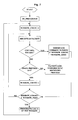
Fig. 3 shows a gateway according to the present invention for achieving content synchronization among a plurality of base stations (eNBs) associated with the access gateway. As shown, the gateway (GW) 100 according to the present invention comprises awindow setting unit 101 for setting and informing the size of a window to all eNBs associated with thegateway 100; a GWwindow counting unit 102 for counting IP packets within a window; a sequencenumber counting unit 103 for counting IP packets to be transmitted, so as to generate a sequence number for each IP packet; atimer 104 for performing a timing operation; aGW receiving unit 105 for receiving an IP packet to be transmitted; aGW processing unit 106 for processing the IP packet to be transmitted; a sync controlpacket generation unit 107 for generating a sync control packet; aGW transmission unit 108 for transmitting the IP packet processed by theprocessing unit 106 or the sync control packet generated by the sync controlpacket generation unit 107 to all base stations associated with the gateway; and atimestamp setting unit 109 for setting a timestamp. The operation of thegateway 100 according to the present invention is illustrated inFig. 4 . - Initially, the
window setting unit 101 of thegateway 100 defines a parameter for window size, WINDOW_SIZE, and informs the base stations. For the sake of convenience, the window size is assumed to be WINDOW_SIZE=5, where the numeral 5 denotes 5 packets at the S1 interface. It is further assumed that a service starts with the first packet with a sequence number of 0 from which the first window starts. Thus, the sequencenumber counting unit 103 counts the sequence number (SN) from zero and the GWwindow counting unit 102 also starts counting the window as WINDOW_COUNT. In this way, when theGW receiving unit 105 receives an IP packet transmitted from a broadcast multicast service center, the sequencenumber counting unit 103 increments the sequence number by one to generate the sequence number of the IP packet. The IP packet is processed byGW processing unit 106, as described hereinafter, and then transmitted by theGW transmission unit 108 to all the base stations associated with thegateway 100 in an IP multicast manner. - Firstly, the gateway adds to the header of each packet a layer of sync protocol which comprises the three items: 1) a sequence number counted by the sequence
number counting unit 103 where the sequence number is counted, for example, from 0 to 65535 in a round-bin manner; 2) a timestamp which in an embodiment of the present invention is the time at which the first packet of a window is transmitted from the gateway plus a maximum transmission delay, a maximum processing delay and a delay margin, the maximum transmission delay being a maximum delay required for transmission of a packet from the gateway to all the base stations associated with the gateway, and the maximum processing delay being a maximum processing delay required for a packet from being processed at L2 to being transmitted via an air interface at all of the base stations; and 3) a byte count indicating the amount of the bytes of all the packets in the previous window, the byte count included in each packet of the window being the same. - According to this embodiment of the present invention, the timestamps of all the packets within a window are set to be identical. That is, all the packets within a window have the same timestamp which is the timestamp of the first packet. Of course, the timestamps within a window can be different as noted above, as long as the timestamps are associated with each other. In other words, the location relationship among the timestamps within a window can be derived from their corresponding sequence numbers, and thus a timestamp of a packet can be derived from timestamps of other packets in the same window.
- The gateway adds a layer of sync protocol to the header of each packet and transmits the packet to all the base stations associated with the gateway in an IP multicast manner.
- Each time the
GW transmission unit 108 transmits a packet, the GWwindow counting unit 102 increments the window count by one. When the window count reaches the window size, WINDOW_SIZE (e.g., 5), it indicates that the next packet is the start of a new window. At this time, the window count is reset and theGW receiving unit 105 waits for receiving the next IP packet. - The gateway is configured with a timer, e.g., a
timer 104, for avoiding the case where the next packet to be received by the gateway fails to arrive for a long time. The length of the timer is set to be T, where T=delay margin/N and N is the number as defined above. The timer expires when a period of the length of T has elapsed since a packet transmitted from the broadcast multicast service arrived at the gateway without arrival of the next packet. As such, the gateway transmits to the base stations a sync control packet indicating the termination of the current window. In this case, the window ends although the size of the window has not been reached yet. The sync control packet is generated by the sync controlpacket generation unit 107 and comprises the following fields: a sequence number which is the sequence number of the next data packet to be transmitted; a timestamp which is the time at which the sync control packet is transmitted from the gateway plus the maximum transmission delay, the maximum processing delay and the delay margin; and a total byte count of all the packets within the currently terminated window. The length T of the timer is set as T=delay margin/N, such that the sync control packet can be retransmitted N times within the duration of the delay margin to ensure reliable transmission of the sync control packet. - When the next data packet arrives at the gateway, it indicates the start of a new window for which all the related operations are the same as the previous window. Although the sync control packet has a sequence number field, it indicates the sequence number of the next data packet to be transmitted. Thus, the sync control packet is not involved in the counting of sequence number, as shown in
Fig. 5 . - The gateway according to the present invention performs the above process cyclically to transmit the received IP packet or the sync control packet to its associated base stations.
-
Fig. 6 illustrates the base station according to the present invention. The base station (Node B) 200 according to the present invention comprises: aNB receiving unit 201 for receiving a packet; aninformation extracting unit 202 for extracting a sequence number, a timestamp and a byte count from the received data; a sync controlpacket determining unit 203 for determining whether the received packet is a sync control packet; a packetloss determining unit 204 for determining whether there is a packet loss; a NBwindow counting unit 205 for counting IP packets of a window; aNB processing unit 206 for processing all the IP packets within the window; abase station buffer 207 for buffering the IP data packet received from the gateway; a packetloss processing unit 208 for performing a packet loss process when the packetloss determining unit 204 determines that there is a packet loss. -
Fig. 7 shows the operation of the base station 200 ofFig. 6 . Again, it is assumed that the service starts with the first packet with a sequence number of 0 from which the first window starts. Of course, N sync control packets can be sent prior to the start of a service data packet, so as to indicate to the base station the start of the window. - The
NB receiving unit 201 of the base station receives data packets from the first packet of the first window. Each time the base station receives a packet, theinformation extracting unit 202 extracts the values of the following fields from the sync protocol of the packet: a sequence number; a timestamp indicating the time at which the packet of the previous window was transmitted over the air interface; and a byte count for recovering the number of bytes of the packet possibly lost in the previous window. - Herein, the packet
loss determining unit 204 can determine whether there is a packet loss prior to the received packet based on the continuity of the sequence number. If there is a packet loss, it can be determined how many packets are lost based on the difference between the sequence number of the received packet and the sequence number of the last received packet. Meanwhile, thewindow counting unit 205 counts the sequence number of the received data packet. When the count reaches the window size, it indicates that the next data packet is the start of a new window. The counting of the window is based on the sequence number, rather than the received data packet. For example, assuming that the current window starts with the packet having the sequence number of 0, the packets having the respective sequence numbers of 0, 1, 2, 3 and 6 are received. In this case, the packets in the current window have the sequence numbers of 0, 1, 2, 3 and 4, respectively, and the packets in the next window have the sequence number of 5, 6, ..., respectively. Upon receipt of the packet with the sequence number of 6, the packetloss determining unit 203 can determine that two packets are lost for the current window and one for the next window, based on the difference between thesequence number 6 and thesequence number 3 of the last received packet as well as the window size of 5. A process for packet loss is performed upon determination of the packet loss. - Each time the base station has received all the packets of a window and started receiving data packets of the next window, the
processing unit 206 of the base station processes the packets of the window in which all the packets are received. That is, theprocessing unit 206 assigns the timestamp included in the sync protocol in the data packet of the next window to the data packets of the current window and names it as an anticipated air interface transmission time which is placed into the L2 (RLC) buffer together with all the data packets of the window. The anticipated air interface transmission time means that the data packets are filled into a transmission block of an air interface protocol frame, which should be transmitted over the air interface exactly at or later than that time. - Each time the base station has received all the packets of a window and started receiving data packets of the next window, all the packets of the window can be processed by a L2 user interface of the base station and transmitted over the air interface. Of course, any packet pertaining to a window prior to this window which remains in the L2 buffer and has not been transmitted over the air interface is required to be transmitted over the air interface sequentially.
- When the sync
packet determining unit 203 of the base station determines that one or more consecutive sync control packets are received, it indicates that the current window is terminated by the sync control packets and the last packet of the current window has a sequence number that is the sequence number of the synccontrol packet minus 1. In this case, the packets within the window are illustrated inFig. 5 . All the processes for these packets are the same as the case where all the packets of a window are received. That is, the base station assigns the timestamp included in the sync control packet to the data packets of the current window and names it as an anticipated air interface transmission time which is placed into the L2 (RLC) buffer together with all the data packets of the window. - If the base station receives a packet and the packet
loss determining unit 204 detects the discontinuity between the sequence number of the received packet and the sequence number of the last received packet, it indicates that there is a packet loss and the synchronization recovery process by the packetloss processing unit 208 is required. Each time the base station has received all the packets of a window and started receiving data packets of the next window, or the current window is terminated by a sync control packet, the base station obtains the total byte count of all the packets received in the current window and then extracts the byte count from the data packet of the next window or the sync control packet. The total byte count of all the packets lost in the current window can be calculated by subtracting the total byte count from the extracted byte count. The number of packets lost in the current window can be obtained based on the discontinuous sequence numbers. The lost packets are recovered by means of regeneration. If the number of the lost packet equals to 1, the length of the lost packet is the byte count of the single packet determined to be lost in the current window. If the number of lost packets is greater than 1, the total length of the lost packets is the total byte count of all the packets determined to be lost in the current window. The length of each packet can be assigned arbitrarily or uniformly. The regenerated packets are identified as dummy and have invalid data content but the same total length as the real packets. L2 knows which packet is the recovered dummy packet, and the transmission block containing such a dummy packet has no transmission power when transmitted over the air interface, i.e., the transmission block is silent. - According to the present invention, the base station further comprises an
alerting unit 209 for informing the gateway or O&M an abnormal network transmission problem if a number of consecutive packets or a number N of consecutive sync control frames are lost, the number of consecutive packets corresponding to the size of a window. - In R3-071920 MBSFN scheduling and content synchronization, Nokia, Nokia Siemens Network, 2007-10, Nokia simply proposed a solution for content synchronization based on fixed burst length. Its "total counter frame" is similar to the sync control packet according to the present invention, and has the similar information, including total byte count of the previous burst (which is in the present invention the previous window), a timestamp, the total number of packets in the previous burst. In Nokia's solution, however, a fixed length burst is defined first as for example 1 second or another value. The frequency of generation of the "total counter frame" is defined according to the burst length. The sync processing delay is also affected by this burst length. According to a simulation for the Nokia solution, only the burst timing length set as 0.5s is acceptable with respect to the performance of sync layer processing delay and the number of control packets.
- In the ALU solution according to the present invention, the window size and burst timing length are two factors critical to the performance. It is more flexible to combine these two parameters to control the performance in terms of the sync layer processing delay and the number of control packets. According to a simulation, the appropriate parameters setting for the ALU solution are a window size of 5 and a burst timing length of 0.1s.
- The parameter setting for the Nokia solution can be a burst timing length of 0.5s.
- Herein, given the above parameters setting, the following comparison is made between the performances of the ALU and Nokia solutions in terms of the sync layer processing delay and the number of control packets.
- For the performance of sync layer processing delay, the ALU solution obtains 0.6768s and the Nokia solution obtains 0.6582s, with a difference of 0.0186s. Thus, these two solutions have the similar sync layer processing delay performance. However, for the number of control packets, there is a significant difference between these two solutions. The ALU solution only generates 695 control packets while the Nokia solution has 11989 control packets, which is 17.25 times as many as the ALU solution. Overall, the ALU solution is superior to the Nokia solution.
- The content synchronization according to the present invention can operate well with statistical multiplexing and fulfill the basic 1 second processing delay requirement with less control packets load.
- Although the present invention has been disclosed above with the preferred embodiments, it can be understood by those who skilled in the art that any modifications and alternatives can be made without departing from the scope of the present invention. Therefore, these modifications and alternatives are encompassed by the scope of the present invention which is defined by the attached claims only.
Claims (36)
- A gateway comprising:a receiving unit for receiving a data packet to be transmitted to base stations;a window counting unit for counting the data packet to be transmitted, such that a predetermined number of packets forms a window, the number being a window size;a sequence number counting unit for generating a sequence number of the packet to be transmitted;a timestamp setting unit for setting a timestamp for each packet within the window, such that the timestamps for all the packets in the window are related to each other; anda processing unit for including the generated sequence number, the timestamp and a byte count in the packet to be transmitted, the byte count being the amount of the bytes of all the packets in the previous window, the byte count included in each packet of the window being the same.
- The gateway of Claim 1, wherein the processing unit adds to the header of the packet to be transmitted a layer of sync protocol which comprises the sequence number, the timestamp and the byte count.
- The gateway of Claim 1 or 2, wherein all the packets in the window have the same timestamp, which is defined as the time at which the gateway transmits the first packet of the window plus a maximum transmission delay, a maximum processing delay and a delay margin, the maximum transmission delay being a maximum delay required for transmission of a packet from the gateway to all the base stations associated with the gateway, and the maximum processing delay being a maximum processing delay required for a packet from being processed at L2 to being transmitted via an air interface at all of the base stations.
- The gateway of Claim 1 or 2, further comprising a timer for timing the period during which the receiving unit receives no data; a sync control packet generating unit for generating a sync control packet when the timer expires; and a transmission unit for transmitting the generated sync control packet.
- The gateway of Claim 4, wherein the sync control packet includes a sequence number which is the sequence number of the next packet to be transmitted; a timestamp which is the time at which the gateway generates the sync control packet plus the maximum transmission delay, the maximum processing delay and the delay margin; and a total byte count of the packets transmitted in the window terminated prior to the sync control packet.
- The gateway of Claim 5, wherein the time length of the timer is set to the delay margin divided by a predetermined number N of retransmissions of the sync control packet.
- The gateway of Claim 1, further comprising a window setting unit for setting and informing the size of a window to all the base stations associated with the gateway.
- A base station comprising:a receiving unit for receiving a data packet from a gateway;an information extracting unit for extracting a sequence number, a timestamp and byte count information from the received data packet;a window counting unit for counting the received packets based on the extracted sequence number so as to form a window; anda processing unit for processing the data packets within the window and setting an anticipated air interface transmission time for the packets in the current window based on the extracted timestamp.
- The base station of Claim 8, wherein the anticipated air interface transmission time for the packets in the current window is set to the timestamp included in the sync protocol for the data packets in the next window.
- The base station of Claim 8 or 9, further comprising a sync control packet determining unit for analyzing the received data packet so as to determine whether the received packet is a sync control packet.
- The base station of Claim 10, wherein the sync control packet includes a sequence number which is a sequence number of the next packet to be transmitted; a timestamp; and a total byte count of the packets transmitted in the window terminated prior to the sync control packet.
- The base station of Claim 11, wherein the window counting unit forms a window based on the sequence number included in the sync control packet when the received packet is a sync control packet.
- The base station of Claim 8 or 12, further comprising a packet loss determining unit for determining whether there is a packet loss based on the sequence number of the received packet or sync control packet, and performing a packet loss process when there is a packet loss.
- The base station of Claim 13, wherein the packet loss determining unit determiners whether there is a packet loss based on the continuity between the sequence number of the previously received packet and the sequence number of the currently received packet or sync control packet.
- The base station of Claim 14, wherein the packet loss process comprises regenerating a number of packets, such that the number of the regenerated packets is the difference between the discontinuous sequence numbers, and the byte count of the regenerated packets is the difference between the total byte count of the received packets in the current window and the byte count included in the data packets of the next window or the total byte count included in the sync control packet.
- The base station of Claim 15, wherein the length of the respective packets to be regenerated can be arbitrarily selected or evenly assigned when the number of the packets to be regenerated is larger than one.
- The base station of Claim 13, further comprising an alerting unit for informing the gateway of a network transmission failure when a number of consecutive packets or a number N of consecutive sync control packets are lost, wherein said number of consecutive packets corresponds to the size of a window and said number N corresponds to the predetermined number of retransmissions.
- The base station of Claim 14, further comprising an alerting unit for informing the gateway of a network transmission failure when a number of consecutive packets or a number N of consecutive sync control packets are lost, wherein said number of consecutive packets corresponds to the size of a window and said number N corresponds to the predetermined number of retransmissions.
- A method for processing data packets in a gateway for content synchronization, comprising the steps of:receiving a data packet to be transmitted to base stations;counting the data packet to be transmitted, such that a predetermined number of packets forms a window, the number being a window size;generating a sequence number of the packet to be transmitted;setting a timestamp for each packet within the window, such that the timestamps for all the packets in the window are related to each other; andincluding the generated sequence number, the timestamp and a byte count in the packet to be transmitted, the byte count being the amount of the bytes of all the packets in the previous window, the byte count included in each packet of the window being the same.
- The method of Claim 19, wherein the step of including the generated sequence number, the timestamp and the byte count in the packet to be transmitted comprises adding to the header of the packet to be transmitted a layer of sync protocol which comprises the sequence number, the timestamp and the byte count.
- The method of Claim 19 or 20, wherein all the packets in the window have the same timestamp, which is defined as the time at which the gateway transmits the first packet of the window plus a maximum transmission delay, a maximum processing delay and a delay margin, the maximum transmission delay being a maximum delay required for transmission of a packet from the gateway to all the base stations associated with the gateway, and the maximum processing delay being a maximum processing delay required for a packet from being processed at L2 to being transmitted via an air interface at all of the base stations.
- The method of Claim 19 or 20, further comprising a step of timing the period during which the receiving unit receives no data; generating a sync control packet when the timing expires; and transmitting the generated sync control packet.
- The method of Claim 22, wherein the sync control packet includes a sequence number which is the sequence number of the next packet to be transmitted; a timestamp which is the time at which the gateway generates the sync control packet plus a maximum transmission delay, the maximum processing delay and the delay margin; and a total byte count of the packets transmitted in the window terminated prior to the sync control packet.
- The method of Claim 23, wherein the length of the timing is set to the delay margin divided by a predetermined number N of retransmissions of the sync control packet.
- The method of Claim 19, further comprising a step of setting and informing the size of a window to all the base stations associated with the gateway.
- A method for processing data packets in a base station for content synchronization, comprising the steps of:receiving a data packet from a gateway;extracting a sequence number, a timestamp and byte count information from the received data packet;counting the received packets based on the extracted sequence number so as to form a window; andprocessing the data packets within the window and setting an anticipated air interface transmission time for the packets in the current window based on the extracted timestamp.
- The method of Claim 26, wherein the step of setting an anticipated air interface transmission time for the packets in the current window based on the extracted timestamp comprises setting the anticipated air interface transmission time for the packets in the current window to the timestamp included in the sync protocol for the data packets in the next window.
- The method of Claim 26 or 27, further comprising a step of analyzing the received data packet so as to determine whether the received packet is a sync control packet.
- The method of Claim 28, wherein the sync control packet includes a sequence number which is a sequence number of the next packet to be transmitted; a timestamp; and a total byte count of the packets transmitted in the window terminated prior to the sync control packet.
- The method of Claim 29, wherein when the received packet is a sync control packet, a window is formed based on the sequence number included in the sync control packet.
- The method of Claim 26 or 30, further comprising a step of determining whether there is a packet loss based on the sequence number of the received packet or sync control packet, and a step of performing a packet loss process when there is a packet loss.
- The method of Claim 31, wherein the step of determining whether there is a packet loss comprises: determining whether there is a packet loss based on the continuity between the sequence number of the previously received packet and the sequence number of the currently received packet or sync control packet.
- The method of Claim 32, wherein the packet loss process comprises regenerating a number of packets such that the number of the regenerated packets is the difference between the discontinuous sequence numbers and the byte count of the regenerated packets is the difference between the total byte count of the received packets in the current window and the byte count included in the data packets of the next window or the total byte count included in the sync control packet.
- The method of Claim 33, wherein the length of the respective packets to be regenerated can be arbitrarily selected or evenly assigned when the number of the packets to be regenerated is larger than one.
- The method of Claim 31, further comprising a step of informing the gateway of a network transmission failure when a number of consecutive packets of a number N of consecutive sync control packets are lost, wherein said number of consecutive packets corresponds to the size of a window and said number N corresponds to the predetermined number of retransmissions.
- The method of Claim 32, further comprising a step of informing the gateway of a network transmission failure when a number of consecutive packets or a number N of consecutive sync control packets are lost, wherein said number of consecutive packets corresponds to the size of a window and said number N corresponds to the predetermined number of retransmissions.
Applications Claiming Priority (2)
| Application Number | Priority Date | Filing Date | Title |
|---|---|---|---|
| CN200810033551.2A CN101500341B (en) | 2008-02-02 | 2008-02-02 | Gateway and base station for content synchronization based on window and method thereof |
| PCT/CN2009/000109 WO2009097744A1 (en) | 2008-02-02 | 2009-01-23 | Gateway and base station based on content synchronization of window and its method |
Publications (3)
| Publication Number | Publication Date |
|---|---|
| EP2239880A1 true EP2239880A1 (en) | 2010-10-13 |
| EP2239880A4 EP2239880A4 (en) | 2013-01-02 |
| EP2239880B1 EP2239880B1 (en) | 2014-09-24 |
Family
ID=40947154
Family Applications (1)
| Application Number | Title | Priority Date | Filing Date |
|---|---|---|---|
| EP09709304.1A Active EP2239880B1 (en) | 2008-02-02 | 2009-01-23 | Gateway and base station based on content synchronization of window and its method |
Country Status (7)
| Country | Link |
|---|---|
| US (1) | US8509240B2 (en) |
| EP (1) | EP2239880B1 (en) |
| JP (1) | JP5296102B2 (en) |
| KR (1) | KR101503247B1 (en) |
| CN (1) | CN101500341B (en) |
| ES (1) | ES2524592T3 (en) |
| WO (1) | WO2009097744A1 (en) |
Cited By (3)
| Publication number | Priority date | Publication date | Assignee | Title |
|---|---|---|---|---|
| CN102771068A (en) * | 2012-05-09 | 2012-11-07 | 华为技术有限公司 | Information transmission method and device |
| US11696260B2 (en) | 2005-12-14 | 2023-07-04 | Blackberry Limited | Method and apparatus for user equipment directed radio resource control in a UMTS network |
| US11792875B2 (en) * | 2009-11-23 | 2023-10-17 | Blackberry Limited | Method and apparatus for state/mode transitioning |
Families Citing this family (24)
| Publication number | Priority date | Publication date | Assignee | Title |
|---|---|---|---|---|
| WO2006105010A1 (en) | 2005-03-25 | 2006-10-05 | Neocific, Inc. | Methods and apparatus for cellular broadcasting and communication system |
| CN101091390B (en) | 2005-06-09 | 2011-01-12 | 桥扬科技有限公司 | Method and apparatus for power efficient broadcast and communication system |
| CN101132222B (en) * | 2006-08-22 | 2011-02-16 | 上海贝尔阿尔卡特股份有限公司 | Gateway equipment, communication network and synchronization method |
| GB0711833D0 (en) * | 2007-06-18 | 2007-07-25 | Nokia Siemens Networks Oy | A method for providing a plurality of services |
| US8656170B2 (en) * | 2010-05-28 | 2014-02-18 | Cisco Technology, Inc. | Protection of control plane traffic against replayed and delayed packet attack |
| JP5243499B2 (en) * | 2010-08-06 | 2013-07-24 | Necエンジニアリング株式会社 | Space equipment synchronization system and space equipment used therefor |
| WO2012050838A1 (en) | 2010-09-28 | 2012-04-19 | Neocific, Inc. | Methods and apparatus for flexible use of frequency bands |
| WO2012044234A1 (en) | 2010-09-29 | 2012-04-05 | Telefonaktiebolaget L M Ericsson (Publ) | Determining loss of ip packets |
| CN102065472B (en) * | 2010-12-09 | 2013-02-06 | 重庆邮电大学 | Method for Determining Participating Groups of Wireless Network Coding Based on Cross-Layer Design |
| WO2013171745A1 (en) | 2012-05-13 | 2013-11-21 | Lacoon Security Ltd. | Anti-malware detection and removal systems and methods |
| CN103609050B (en) * | 2012-09-07 | 2017-08-18 | 华为技术有限公司 | An air interface transmission method and related equipment and system |
| IN2015DN02414A (en) | 2012-10-31 | 2015-09-04 | Ericsson Telefon Ab L M | |
| US20140293825A1 (en) * | 2013-03-27 | 2014-10-02 | Broadcom Corporation | Timestamping data packets |
| US9525611B2 (en) | 2014-01-27 | 2016-12-20 | Imagine Communications Corp. | Transmission system implementing delay measurement and control |
| CN105471825B (en) * | 2014-09-03 | 2019-08-23 | 南京中兴软件有限责任公司 | Lose recognition methods and the device of data message |
| CN105450356B (en) * | 2014-09-03 | 2019-10-11 | 中兴通讯股份有限公司 | Recovery processing method and device for lost data |
| US9910809B2 (en) * | 2014-12-19 | 2018-03-06 | Intel Corporation | High performance interconnect link state transitions |
| US9526078B1 (en) | 2015-01-26 | 2016-12-20 | Sprint Communications Company L.P. | Wireless communication system to synchronize a single frequency network |
| US10313143B1 (en) * | 2015-02-23 | 2019-06-04 | Sprint Communications Company L.P. | Wireless communication system to provide buffering in a single frequency network |
| US10212065B2 (en) | 2016-10-20 | 2019-02-19 | Gatesair, Inc. | Extended time reference generation |
| WO2021177866A1 (en) | 2020-03-02 | 2021-09-10 | Telefonaktiebolaget Lm Ericsson (Publ) | Over the air antenna synchronization in wireless communication network |
| WO2022012274A1 (en) * | 2020-07-14 | 2022-01-20 | 上海朗帛通信技术有限公司 | Sidelink relay wireless communication method and apparatus |
| EP4598235A3 (en) * | 2020-08-03 | 2025-10-15 | Kyocera Corporation | Communication control method |
| CN115175300B (en) * | 2022-08-17 | 2023-10-31 | 上海磐启微电子有限公司 | Clock calibration method of Bluetooth ad hoc network system |
Family Cites Families (10)
| Publication number | Priority date | Publication date | Assignee | Title |
|---|---|---|---|---|
| US6643276B1 (en) * | 1998-11-30 | 2003-11-04 | Motorola, Inc. | Data gateway and method for conveying data to a base site in a communication system |
| FI106498B (en) * | 1999-03-16 | 2001-02-15 | Nokia Mobile Phones Ltd | Procedure for selecting a transfer window and mobile station |
| US6941132B2 (en) * | 2000-03-20 | 2005-09-06 | Telefonaktiebolaget L M Ericsson (Publ) | Transport of radio network-originated control information |
| CN1145327C (en) * | 2001-06-05 | 2004-04-07 | 华为技术有限公司 | Method for universal grouped radio business network node to transmit telephone bill to charge network |
| US20050152397A1 (en) * | 2001-09-27 | 2005-07-14 | Junfeng Bai | Communication system and techniques for transmission from source to destination |
| KR100547871B1 (en) * | 2001-11-08 | 2006-02-01 | 삼성전자주식회사 | Method and apparatus for retransmitting packet data between base station controller and base station in mobile communication system |
| US7620071B2 (en) * | 2004-11-16 | 2009-11-17 | Intel Corporation | Packet coalescing |
| US7590165B2 (en) * | 2005-07-08 | 2009-09-15 | Industrial Technology Research Institute | Sub-system based window placement and size decision mechanism and method thereof |
| CN100474807C (en) * | 2005-07-29 | 2009-04-01 | 华为技术有限公司 | Method and device for realizing media gateway synchronization in communication system |
| CN101039175B (en) * | 2007-03-27 | 2011-08-24 | 中兴通讯股份有限公司 | Method and system for synchronizing RLC in wireless network controllers |
-
2008
- 2008-02-02 CN CN200810033551.2A patent/CN101500341B/en active Active
-
2009
- 2009-01-23 KR KR1020107019394A patent/KR101503247B1/en active Active
- 2009-01-23 JP JP2010544564A patent/JP5296102B2/en active Active
- 2009-01-23 US US12/865,777 patent/US8509240B2/en active Active
- 2009-01-23 ES ES09709304.1T patent/ES2524592T3/en active Active
- 2009-01-23 WO PCT/CN2009/000109 patent/WO2009097744A1/en not_active Ceased
- 2009-01-23 EP EP09709304.1A patent/EP2239880B1/en active Active
Non-Patent Citations (6)
| Title |
|---|
| ALCATEL-LUCENT: "Comparison of Robust E-MBMS Content Synchronization Protocols", 3GPP DRAFT; R3-072114 COMPARISON OF ROBUST E-MBMS CONTENT SYNCHRONIZATION, 3RD GENERATION PARTNERSHIP PROJECT (3GPP), MOBILE COMPETENCE CENTRE ; 650, ROUTE DES LUCIOLES ; F-06921 SOPHIA-ANTIPOLIS CEDEX ; FRANCE, vol. RAN WG3, no. Jeju Island; 20071031, 31 October 2007 (2007-10-31), XP050162902, [retrieved on 2007-10-31] * |
| ALCATEL-LUCENT: "Details of eMBMS Content Synchronization", 3GPP DRAFT; R3-070220 (DETAILS OF EMBMS CONTENT SYNCHRONIZATION), 3RD GENERATION PARTNERSHIP PROJECT (3GPP), MOBILE COMPETENCE CENTRE ; 650, ROUTE DES LUCIOLES ; F-06921 SOPHIA-ANTIPOLIS CEDEX ; FRANCE, vol. RAN WG3, no. St. Louis, Missouri; 20070207, 7 February 2007 (2007-02-07), XP050161148, [retrieved on 2007-02-07] * |
| ERICSSON: "MBMS L2 content synchronization", 3GPP DRAFT; R3-070630, 3RD GENERATION PARTNERSHIP PROJECT (3GPP), MOBILE COMPETENCE CENTRE ; 650, ROUTE DES LUCIOLES ; F-06921 SOPHIA-ANTIPOLIS CEDEX ; FRANCE, vol. RAN WG3, no. St. Julian, Malta; 20070322, 22 March 2007 (2007-03-22), XP050161531, [retrieved on 2007-03-22] * |
| MOTOROLA: "LTE MBMS content synchronization", 3GPP DRAFT; R3-070649, 3RD GENERATION PARTNERSHIP PROJECT (3GPP), MOBILE COMPETENCE CENTRE ; 650, ROUTE DES LUCIOLES ; F-06921 SOPHIA-ANTIPOLIS CEDEX ; FRANCE, vol. RAN WG3, no. St. Julian, Malta; 20070321, 21 March 2007 (2007-03-21), XP050161548, [retrieved on 2007-03-21] * |
| NOKIA ET AL: "MBSFN Scheduling and Content Synchronization", 3GPP DRAFT; R3-071920 MBSFN SCHEDULING AND CONTENT SYNCHRONIZATION, 3RD GENERATION PARTNERSHIP PROJECT (3GPP), MOBILE COMPETENCE CENTRE ; 650, ROUTE DES LUCIOLES ; F-06921 SOPHIA-ANTIPOLIS CEDEX ; FRANCE, vol. RAN WG3, no. Sophia Antipolis, France; 20071003, 3 October 2007 (2007-10-03), XP050162710, [retrieved on 2007-10-03] * |
| See also references of WO2009097744A1 * |
Cited By (4)
| Publication number | Priority date | Publication date | Assignee | Title |
|---|---|---|---|---|
| US11696260B2 (en) | 2005-12-14 | 2023-07-04 | Blackberry Limited | Method and apparatus for user equipment directed radio resource control in a UMTS network |
| US11792875B2 (en) * | 2009-11-23 | 2023-10-17 | Blackberry Limited | Method and apparatus for state/mode transitioning |
| CN102771068A (en) * | 2012-05-09 | 2012-11-07 | 华为技术有限公司 | Information transmission method and device |
| CN102771068B (en) * | 2012-05-09 | 2015-03-11 | 华为技术有限公司 | Information transmission method and device |
Also Published As
| Publication number | Publication date |
|---|---|
| WO2009097744A1 (en) | 2009-08-13 |
| KR101503247B1 (en) | 2015-03-17 |
| JP2011514705A (en) | 2011-05-06 |
| EP2239880A4 (en) | 2013-01-02 |
| US8509240B2 (en) | 2013-08-13 |
| US20110002311A1 (en) | 2011-01-06 |
| CN101500341A (en) | 2009-08-05 |
| ES2524592T3 (en) | 2014-12-10 |
| KR20100113614A (en) | 2010-10-21 |
| CN101500341B (en) | 2011-02-02 |
| EP2239880B1 (en) | 2014-09-24 |
| JP5296102B2 (en) | 2013-09-25 |
Similar Documents
| Publication | Publication Date | Title |
|---|---|---|
| EP2239880B1 (en) | Gateway and base station based on content synchronization of window and its method | |
| CN101741701B (en) | Synchronous dispatching method and synchronous dispatching device | |
| US8005085B2 (en) | Method for distribution of data packets in a single frequency mobile communication network, an access network node, a base station and a single frequency mobile communication network therefor | |
| CN100469172C (en) | Wireless communication system with robust radio link control reset procedure | |
| KR100663463B1 (en) | Method and apparatus for signaling of uestatus information for uplink data transmission in a mobile communication system | |
| EP2082506B1 (en) | Method for content synchronization when broadcasting data in a wireless network | |
| CN101741538B (en) | Synchronous dispatching method | |
| EP2320599B1 (en) | Method and apparatus for recovery processing of synchronously transmitted service data | |
| EP3065456A1 (en) | User equipment and method | |
| EP2471223B1 (en) | Enhanced multiplexing for single rlc entity | |
| CN105898857B (en) | Data synchronization method and system | |
| KR20060090191A (en) | Method and device for requesting / transmission of status report for retransmission control in mobile communication system | |
| KR20080095727A (en) | Method and apparatus for packet transmission and reception in mobile communication system | |
| EP2346204B1 (en) | Method and apparatus for synchronization processing | |
| CN101741499B (en) | Synchronous dispatching method | |
| WO2015154523A1 (en) | Lost data recovery processing method and device | |
| CN102056084B (en) | Multimedia broadcast multicast service system and synchronous method thereof | |
| CN121666838A (en) | Wireless communication method and apparatus | |
| WO2007078169A1 (en) | Apparatus and method for transmitting/receiving arq packet in mobile communication system |
Legal Events
| Date | Code | Title | Description |
|---|---|---|---|
| PUAI | Public reference made under article 153(3) epc to a published international application that has entered the european phase |
Free format text: ORIGINAL CODE: 0009012 |
|
| 17P | Request for examination filed |
Effective date: 20100805 |
|
| AK | Designated contracting states |
Kind code of ref document: A1 Designated state(s): AT BE BG CH CY CZ DE DK EE ES FI FR GB GR HR HU IE IS IT LI LT LU LV MC MK MT NL NO PL PT RO SE SI SK TR |
|
| AX | Request for extension of the european patent |
Extension state: AL BA RS |
|
| DAX | Request for extension of the european patent (deleted) | ||
| RAP1 | Party data changed (applicant data changed or rights of an application transferred) |
Owner name: ALCATEL LUCENT |
|
| A4 | Supplementary search report drawn up and despatched |
Effective date: 20121204 |
|
| RIC1 | Information provided on ipc code assigned before grant |
Ipc: H04L 7/06 20060101AFI20121128BHEP Ipc: H04L 12/56 00000000ALI20121128BHEP Ipc: H04H 20/67 20080101ALI20121128BHEP |
|
| 17Q | First examination report despatched |
Effective date: 20130328 |
|
| RIC1 | Information provided on ipc code assigned before grant |
Ipc: H04L 7/06 20060101AFI20130716BHEP Ipc: H04H 20/67 20080101ALI20130716BHEP |
|
| 111Z | Information provided on other rights and legal means of execution |
Free format text: AT BE BG CH CY CZ DE DK EE ES FI FR GB GR HR HU IE IS IT LI LT LU LV MC MK MT NL NO PL PT RO SE SI SK TR Effective date: 20130410 |
|
| GRAJ | Information related to disapproval of communication of intention to grant by the applicant or resumption of examination proceedings by the epo deleted |
Free format text: ORIGINAL CODE: EPIDOSDIGR1 |
|
| GRAP | Despatch of communication of intention to grant a patent |
Free format text: ORIGINAL CODE: EPIDOSNIGR1 |
|
| GRAP | Despatch of communication of intention to grant a patent |
Free format text: ORIGINAL CODE: EPIDOSNIGR1 |
|
| INTG | Intention to grant announced |
Effective date: 20140401 |
|
| INTG | Intention to grant announced |
Effective date: 20140410 |
|
| GRAS | Grant fee paid |
Free format text: ORIGINAL CODE: EPIDOSNIGR3 |
|
| RAP1 | Party data changed (applicant data changed or rights of an application transferred) |
Owner name: ALCATEL LUCENT |
|
| GRAA | (expected) grant |
Free format text: ORIGINAL CODE: 0009210 |
|
| AK | Designated contracting states |
Kind code of ref document: B1 Designated state(s): AT BE BG CH CY CZ DE DK EE ES FI FR GB GR HR HU IE IS IT LI LT LU LV MC MK MT NL NO PL PT RO SE SI SK TR |
|
| REG | Reference to a national code |
Ref country code: GB Ref legal event code: FG4D |
|
| REG | Reference to a national code |
Ref country code: CH Ref legal event code: EP |
|
| REG | Reference to a national code |
Ref country code: AT Ref legal event code: REF Ref document number: 689000 Country of ref document: AT Kind code of ref document: T Effective date: 20141015 |
|
| REG | Reference to a national code |
Ref country code: IE Ref legal event code: FG4D |
|
| REG | Reference to a national code |
Ref country code: DE Ref legal event code: R096 Ref document number: 602009026814 Country of ref document: DE Effective date: 20141106 |
|
| D11X | Information provided on other rights and legal means of execution (deleted) | ||
| REG | Reference to a national code |
Ref country code: ES Ref legal event code: FG2A Ref document number: 2524592 Country of ref document: ES Kind code of ref document: T3 Effective date: 20141210 |
|
| REG | Reference to a national code |
Ref country code: FR Ref legal event code: PLFP Year of fee payment: 7 |
|
| PG25 | Lapsed in a contracting state [announced via postgrant information from national office to epo] |
Ref country code: LT Free format text: LAPSE BECAUSE OF FAILURE TO SUBMIT A TRANSLATION OF THE DESCRIPTION OR TO PAY THE FEE WITHIN THE PRESCRIBED TIME-LIMIT Effective date: 20140924 Ref country code: SE Free format text: LAPSE BECAUSE OF FAILURE TO SUBMIT A TRANSLATION OF THE DESCRIPTION OR TO PAY THE FEE WITHIN THE PRESCRIBED TIME-LIMIT Effective date: 20140924 Ref country code: NO Free format text: LAPSE BECAUSE OF FAILURE TO SUBMIT A TRANSLATION OF THE DESCRIPTION OR TO PAY THE FEE WITHIN THE PRESCRIBED TIME-LIMIT Effective date: 20141224 Ref country code: GR Free format text: LAPSE BECAUSE OF FAILURE TO SUBMIT A TRANSLATION OF THE DESCRIPTION OR TO PAY THE FEE WITHIN THE PRESCRIBED TIME-LIMIT Effective date: 20141225 Ref country code: FI Free format text: LAPSE BECAUSE OF FAILURE TO SUBMIT A TRANSLATION OF THE DESCRIPTION OR TO PAY THE FEE WITHIN THE PRESCRIBED TIME-LIMIT Effective date: 20140924 |
|
| REG | Reference to a national code |
Ref country code: LT Ref legal event code: MG4D Ref country code: NL Ref legal event code: VDEP Effective date: 20140924 |
|
| PG25 | Lapsed in a contracting state [announced via postgrant information from national office to epo] |
Ref country code: CY Free format text: LAPSE BECAUSE OF FAILURE TO SUBMIT A TRANSLATION OF THE DESCRIPTION OR TO PAY THE FEE WITHIN THE PRESCRIBED TIME-LIMIT Effective date: 20140924 Ref country code: LV Free format text: LAPSE BECAUSE OF FAILURE TO SUBMIT A TRANSLATION OF THE DESCRIPTION OR TO PAY THE FEE WITHIN THE PRESCRIBED TIME-LIMIT Effective date: 20140924 Ref country code: HR Free format text: LAPSE BECAUSE OF FAILURE TO SUBMIT A TRANSLATION OF THE DESCRIPTION OR TO PAY THE FEE WITHIN THE PRESCRIBED TIME-LIMIT Effective date: 20140924 |
|
| REG | Reference to a national code |
Ref country code: AT Ref legal event code: MK05 Ref document number: 689000 Country of ref document: AT Kind code of ref document: T Effective date: 20140924 |
|
| PG25 | Lapsed in a contracting state [announced via postgrant information from national office to epo] |
Ref country code: NL Free format text: LAPSE BECAUSE OF FAILURE TO SUBMIT A TRANSLATION OF THE DESCRIPTION OR TO PAY THE FEE WITHIN THE PRESCRIBED TIME-LIMIT Effective date: 20140924 |
|
| PG25 | Lapsed in a contracting state [announced via postgrant information from national office to epo] |
Ref country code: PT Free format text: LAPSE BECAUSE OF FAILURE TO SUBMIT A TRANSLATION OF THE DESCRIPTION OR TO PAY THE FEE WITHIN THE PRESCRIBED TIME-LIMIT Effective date: 20150126 Ref country code: EE Free format text: LAPSE BECAUSE OF FAILURE TO SUBMIT A TRANSLATION OF THE DESCRIPTION OR TO PAY THE FEE WITHIN THE PRESCRIBED TIME-LIMIT Effective date: 20140924 Ref country code: SK Free format text: LAPSE BECAUSE OF FAILURE TO SUBMIT A TRANSLATION OF THE DESCRIPTION OR TO PAY THE FEE WITHIN THE PRESCRIBED TIME-LIMIT Effective date: 20140924 Ref country code: RO Free format text: LAPSE BECAUSE OF FAILURE TO SUBMIT A TRANSLATION OF THE DESCRIPTION OR TO PAY THE FEE WITHIN THE PRESCRIBED TIME-LIMIT Effective date: 20140924 Ref country code: IS Free format text: LAPSE BECAUSE OF FAILURE TO SUBMIT A TRANSLATION OF THE DESCRIPTION OR TO PAY THE FEE WITHIN THE PRESCRIBED TIME-LIMIT Effective date: 20150124 Ref country code: CZ Free format text: LAPSE BECAUSE OF FAILURE TO SUBMIT A TRANSLATION OF THE DESCRIPTION OR TO PAY THE FEE WITHIN THE PRESCRIBED TIME-LIMIT Effective date: 20140924 |
|
| PG25 | Lapsed in a contracting state [announced via postgrant information from national office to epo] |
Ref country code: PL Free format text: LAPSE BECAUSE OF FAILURE TO SUBMIT A TRANSLATION OF THE DESCRIPTION OR TO PAY THE FEE WITHIN THE PRESCRIBED TIME-LIMIT Effective date: 20140924 Ref country code: AT Free format text: LAPSE BECAUSE OF FAILURE TO SUBMIT A TRANSLATION OF THE DESCRIPTION OR TO PAY THE FEE WITHIN THE PRESCRIBED TIME-LIMIT Effective date: 20140924 |
|
| REG | Reference to a national code |
Ref country code: DE Ref legal event code: R097 Ref document number: 602009026814 Country of ref document: DE |
|
| PG25 | Lapsed in a contracting state [announced via postgrant information from national office to epo] |
Ref country code: BE Free format text: LAPSE BECAUSE OF NON-PAYMENT OF DUE FEES Effective date: 20150131 |
|
| PG25 | Lapsed in a contracting state [announced via postgrant information from national office to epo] |
Ref country code: DK Free format text: LAPSE BECAUSE OF FAILURE TO SUBMIT A TRANSLATION OF THE DESCRIPTION OR TO PAY THE FEE WITHIN THE PRESCRIBED TIME-LIMIT Effective date: 20140924 |
|
| PLBE | No opposition filed within time limit |
Free format text: ORIGINAL CODE: 0009261 |
|
| STAA | Information on the status of an ep patent application or granted ep patent |
Free format text: STATUS: NO OPPOSITION FILED WITHIN TIME LIMIT |
|
| REG | Reference to a national code |
Ref country code: CH Ref legal event code: PL |
|
| PG25 | Lapsed in a contracting state [announced via postgrant information from national office to epo] |
Ref country code: LU Free format text: LAPSE BECAUSE OF FAILURE TO SUBMIT A TRANSLATION OF THE DESCRIPTION OR TO PAY THE FEE WITHIN THE PRESCRIBED TIME-LIMIT Effective date: 20150123 |
|
| 26N | No opposition filed |
Effective date: 20150625 |
|
| PG25 | Lapsed in a contracting state [announced via postgrant information from national office to epo] |
Ref country code: MC Free format text: LAPSE BECAUSE OF FAILURE TO SUBMIT A TRANSLATION OF THE DESCRIPTION OR TO PAY THE FEE WITHIN THE PRESCRIBED TIME-LIMIT Effective date: 20140924 |
|
| PG25 | Lapsed in a contracting state [announced via postgrant information from national office to epo] |
Ref country code: LI Free format text: LAPSE BECAUSE OF NON-PAYMENT OF DUE FEES Effective date: 20150131 Ref country code: CH Free format text: LAPSE BECAUSE OF NON-PAYMENT OF DUE FEES Effective date: 20150131 |
|
| REG | Reference to a national code |
Ref country code: IE Ref legal event code: MM4A |
|
| REG | Reference to a national code |
Ref country code: FR Ref legal event code: PLFP Year of fee payment: 8 |
|
| PG25 | Lapsed in a contracting state [announced via postgrant information from national office to epo] |
Ref country code: IE Free format text: LAPSE BECAUSE OF NON-PAYMENT OF DUE FEES Effective date: 20150123 |
|
| PG25 | Lapsed in a contracting state [announced via postgrant information from national office to epo] |
Ref country code: SI Free format text: LAPSE BECAUSE OF FAILURE TO SUBMIT A TRANSLATION OF THE DESCRIPTION OR TO PAY THE FEE WITHIN THE PRESCRIBED TIME-LIMIT Effective date: 20140924 |
|
| PG25 | Lapsed in a contracting state [announced via postgrant information from national office to epo] |
Ref country code: MT Free format text: LAPSE BECAUSE OF FAILURE TO SUBMIT A TRANSLATION OF THE DESCRIPTION OR TO PAY THE FEE WITHIN THE PRESCRIBED TIME-LIMIT Effective date: 20140924 |
|
| REG | Reference to a national code |
Ref country code: FR Ref legal event code: PLFP Year of fee payment: 9 |
|
| PG25 | Lapsed in a contracting state [announced via postgrant information from national office to epo] |
Ref country code: BG Free format text: LAPSE BECAUSE OF FAILURE TO SUBMIT A TRANSLATION OF THE DESCRIPTION OR TO PAY THE FEE WITHIN THE PRESCRIBED TIME-LIMIT Effective date: 20140924 Ref country code: HU Free format text: LAPSE BECAUSE OF FAILURE TO SUBMIT A TRANSLATION OF THE DESCRIPTION OR TO PAY THE FEE WITHIN THE PRESCRIBED TIME-LIMIT; INVALID AB INITIO Effective date: 20090123 |
|
| PG25 | Lapsed in a contracting state [announced via postgrant information from national office to epo] |
Ref country code: TR Free format text: LAPSE BECAUSE OF FAILURE TO SUBMIT A TRANSLATION OF THE DESCRIPTION OR TO PAY THE FEE WITHIN THE PRESCRIBED TIME-LIMIT Effective date: 20140924 |
|
| REG | Reference to a national code |
Ref country code: FR Ref legal event code: PLFP Year of fee payment: 10 |
|
| PG25 | Lapsed in a contracting state [announced via postgrant information from national office to epo] |
Ref country code: MK Free format text: LAPSE BECAUSE OF FAILURE TO SUBMIT A TRANSLATION OF THE DESCRIPTION OR TO PAY THE FEE WITHIN THE PRESCRIBED TIME-LIMIT Effective date: 20140924 |
|
| PGFP | Annual fee paid to national office [announced via postgrant information from national office to epo] |
Ref country code: GB Payment date: 20251204 Year of fee payment: 18 |
|
| PGFP | Annual fee paid to national office [announced via postgrant information from national office to epo] |
Ref country code: FR Payment date: 20251208 Year of fee payment: 18 |
|
| PGFP | Annual fee paid to national office [announced via postgrant information from national office to epo] |
Ref country code: ES Payment date: 20260209 Year of fee payment: 18 |
|
| PGFP | Annual fee paid to national office [announced via postgrant information from national office to epo] |
Ref country code: DE Payment date: 20251203 Year of fee payment: 18 |
|
| PGFP | Annual fee paid to national office [announced via postgrant information from national office to epo] |
Ref country code: IT Payment date: 20251219 Year of fee payment: 18 |