EP2239732A1 - Apparatus and method for generating a synthesis audio signal and for encoding an audio signal - Google Patents
Apparatus and method for generating a synthesis audio signal and for encoding an audio signal Download PDFInfo
- Publication number
- EP2239732A1 EP2239732A1 EP09181008A EP09181008A EP2239732A1 EP 2239732 A1 EP2239732 A1 EP 2239732A1 EP 09181008 A EP09181008 A EP 09181008A EP 09181008 A EP09181008 A EP 09181008A EP 2239732 A1 EP2239732 A1 EP 2239732A1
- Authority
- EP
- European Patent Office
- Prior art keywords
- frequency band
- patching
- spectral
- audio signal
- signal
- Prior art date
- Legal status (The legal status is an assumption and is not a legal conclusion. Google has not performed a legal analysis and makes no representation as to the accuracy of the status listed.)
- Withdrawn
Links
Images


Classifications
-
- G—PHYSICS
- G10—MUSICAL INSTRUMENTS; ACOUSTICS
- G10L—SPEECH ANALYSIS OR SYNTHESIS; SPEECH RECOGNITION; SPEECH OR VOICE PROCESSING; SPEECH OR AUDIO CODING OR DECODING
- G10L21/00—Processing of the speech or voice signal to produce another audible or non-audible signal, e.g. visual or tactile, in order to modify its quality or its intelligibility
- G10L21/04—Time compression or expansion
-
- G—PHYSICS
- G10—MUSICAL INSTRUMENTS; ACOUSTICS
- G10L—SPEECH ANALYSIS OR SYNTHESIS; SPEECH RECOGNITION; SPEECH OR VOICE PROCESSING; SPEECH OR AUDIO CODING OR DECODING
- G10L19/00—Speech or audio signals analysis-synthesis techniques for redundancy reduction, e.g. in vocoders; Coding or decoding of speech or audio signals, using source filter models or psychoacoustic analysis
- G10L19/008—Multichannel audio signal coding or decoding using interchannel correlation to reduce redundancy, e.g. joint-stereo, intensity-coding or matrixing
-
- G—PHYSICS
- G10—MUSICAL INSTRUMENTS; ACOUSTICS
- G10L—SPEECH ANALYSIS OR SYNTHESIS; SPEECH RECOGNITION; SPEECH OR VOICE PROCESSING; SPEECH OR AUDIO CODING OR DECODING
- G10L19/00—Speech or audio signals analysis-synthesis techniques for redundancy reduction, e.g. in vocoders; Coding or decoding of speech or audio signals, using source filter models or psychoacoustic analysis
- G10L19/04—Speech or audio signals analysis-synthesis techniques for redundancy reduction, e.g. in vocoders; Coding or decoding of speech or audio signals, using source filter models or psychoacoustic analysis using predictive techniques
- G10L19/16—Vocoder architecture
- G10L19/18—Vocoders using multiple modes
-
- G—PHYSICS
- G10—MUSICAL INSTRUMENTS; ACOUSTICS
- G10L—SPEECH ANALYSIS OR SYNTHESIS; SPEECH RECOGNITION; SPEECH OR VOICE PROCESSING; SPEECH OR AUDIO CODING OR DECODING
- G10L21/00—Processing of the speech or voice signal to produce another audible or non-audible signal, e.g. visual or tactile, in order to modify its quality or its intelligibility
- G10L21/02—Speech enhancement, e.g. noise reduction or echo cancellation
- G10L21/038—Speech enhancement, e.g. noise reduction or echo cancellation using band spreading techniques
Definitions
- the present invention relates to audio signal processing, and in particular, to an apparatus and a method for generating a synthesis audio signal, an apparatus and a method for encoding an audio signal and an encoded audio signal.
- Modem audio codecs are able to code wide-band signals by using bandwidth extension (BWE) methods, as described in M. Dietz, L. Liljeryd, K. Kjörling and O. Kunz, "Spectral Band Replication, a novel approach in audio coding" in 112 th AES Convention, Kunststoff, May 2002; S. Meltzer, R. Böhm and F.
- BWE bandwidth extension
- SBR enhanced audio codecs for digital broadcasting such as "Digital Radio Musice” (DRM),” in 112 th AES Convention, Kunststoff, May 2002; T. Ziegler, A. Ehret, P. Ekstrand and M. Lutzky, "Enhancing mp3 with SBR: Features and Capabilities of the new mp3PRO Algorithm,” in 112 th AES Convention, Kunststoff, May 2002; International Standard ISO/IEC 14496-3:2001/FPDAM 1, “Bandwidth Extension,” ISO/IEC, 2002. Speech bandwidth extension method and apparatus Vasu Iyengar et al. US Patent 5,455,888 ; E. Larsen, R. M. Aarts, and M. Danessis.
- SBR spectral band replication
- the spectral band replication uses a quadrature mirror filterbank (QMF) for generating the HF-information.
- QMF quadrature mirror filterbank
- WO 98/57436 discloses transposition methods used in spectral band replication, which are combined with spectral envelope adjustment.
- WO 02/052545 teaches that signals can be classified either in pulse-train-like or non-pulse-train-like and based on this classification an adaptive switch transposer is proposed.
- the switch transposer performs two patching algorithms in parallel and the mixing unit combines both patched signals dependent on the classification (pulse-train or non-pulse-train).
- the actual switching between or mixing of the transposers is performed in an envelope-adjusting filterbank in response to envelope and control data.
- the base signal is transformed into a filterbank domain, a frequency translating operation performed and an envelope adjustment of the result of the frequency translation is performed. This is a combined patching/further processing procedure.
- a frequency domain transposer For non-pulse-train-like signals, a frequency domain transposer (FD transposer) is provided and the result of the frequency domain transposer is then transformed into the filterbank domain, in which the envelope adjustment is performed.
- FD transposer frequency domain transposer
- an apparatus for generating a synthesis audio signal according to claim 1 an apparatus for encoding an audio signal according to claim 10, a method for generating according to claim 12, a method for encoding according to claim 13, an encoded audio signal according to claim 14 or a computer program according to claim 15.
- the present invention is based on the basic idea that the just-mentioned improved quality and/or efficient implementation may be achieved when a time portion of an audio signal is converted into a spectral representation before performing a plurality of different spectral domain patching algorithms, wherein each patching algorithm generates a modified spectral representation comprising spectral components in an upper frequency band derived from corresponding spectral components in a core frequency band of the audio signal, and selecting a first spectral domain patching algorithm from the plurality of patching algorithms for a first time portion and a second spectral domain patching algorithm from the plurality of patching algorithms for a second different time portion in accordance with a patching control signal to obtain the modified spectral representation.
- a reduced quality and/or flexibility due to a switching between two patching algorithms in different domains may be prevented and therefore the processing may be less complex while maintaining the perceptual quality.
- an apparatus for generating a synthesis audio signal using a patching control signal comprises a first converter, a spectral domain patch generator, a high frequency reconstruction manipulator and a combiner.
- the first converter is configured for converting a time portion of an audio signal into a spectral representation.
- the spectral domain patch generator is configured for performing a plurality of different spectral domain patching algorithms, wherein each patching algorithm generates a modified spectral representation comprising spectral components in an upper frequency band derived from corresponding spectral components in a core frequency band of the audio signal.
- the spectral domain patch generator is furthermore configured to select a first spectral domain patching algorithm from the plurality of patching algorithms for a first time portion and a second spectral domain patching algorithm from the plurality of patching algorithms for a second different time portion in accordance with the patching control signal to obtain the modified spectral representation.
- the high frequency reconstruction manipulator is configured for manipulating the modified spectral representation or a signal derived from the modified spectral representation in accordance with a spectral band replication parameter to obtain a bandwidth extended signal.
- the combiner is configured for combining the audio signal having spectral components in the core frequency band or a signal derived from the audio signal with the bandwidth extended signal to obtain the synthesis audio signal.
- an apparatus for encoding an audio signal comprises a core encoder, a parameter extractor and a parameter calculator.
- the audio signal comprises a core frequency band and an upper frequency band.
- the core encoder is configured for encoding the audio signal within the core frequency band.
- the parameter extractor is configured for extracting a patching control signal from the audio signal, the patching control signal indicating a selected patching algorithm from a plurality of different spectral domain patching algorithm, the selected patching algorithm to be performed in a spectral domain for generating a synthesis audio signal in a bandwidth extension decoder.
- the parameter calculator is configured for calculating the spectral band replication parameter from the upper frequency band.
- an encoded audio signal data stream comprises an encoded audio signal encoded within a core frequency band, a patching control signal, the patching control signal indicating a selected patching algorithm from a plurality of different spectral domain patching algorithms, the selected patching algorithm to be performed in the spectral domain for generating a synthesis audio signal in a bandwidth extension decoder and a spectral band replication parameter calculated from an upper frequency band of the audio signal.
- embodiments of the present invention relate to a concept for switching between at least two different spectral domain patching algorithms from a group of patching algorithms in the spectral domain.
- the group of patching algorithms may comprise a first patching algorithm comprising a harmonic transposition based on a single phase vocoder and non-harmonic copying-up SBR functionalities, a second patching algorithm comprising a harmonic transposition based on a multiple phase vocoder, a third patching algorithm comprising non-harmonic copying-up SBR functionalities and a fourth patching algorithm comprising a non-linear distortion.
- the bandwidth extension may be performed such that the bandwidth extended signal comprises the upper frequency band having a maximum frequency of at least four times the crossover frequency in the core frequency band.
- inventions relate to an apparatus not comprising a time/frequency transformer for transforming a time domain signal derived from the modified spectral representation into the spectral domain. Therefore, embodiments allow that the high frequency reconstruction manipulator may be operative on the modified spectral representation directly without requiring a further transform (e.g. a QMF analysis) from the time domain to the spectral domain such as in case of a combined patching/further processing approach being operative in different domains.
- a further transform e.g. a QMF analysis
- embodiments of the present invention relate to a parameter extractor which is configured for determining from the plurality of different spectral domain patching algorithms a selected patching algorithm.
- the selected patching algorithm is based on a comparison of the audio signal or a signal derived from the audio signal with a plurality of bandwidth extended signals having been obtained by performing the plurality of patching algorithms in the spectral domain and manipulating a modified spectral representation of a time portion of the audio signal. Therefore, embodiments provide a method of selecting the optimal patching algorithm for generating a synthesis audio signal in a bandwidth extension decoder.
- Control parameters may be used to decide which patching is the most appropriate.
- an analysis-by-synthesis stage can be used; i.e. all patches can be applied and the best according to an objective is chosen.
- the objective is to get the best perceptual quality of the restitution.
- an objective function has to be optimized.
- the objective may be to preserve the spectral flatness of the original HFs as close as possible.
- the patching selection can be done only at the encoder by considering the original signal, the synthesized signal or the both of them.
- the decision (patching control signal) is then transmitted to the decoder.
- the selection may be performed synchronously at the encoder and decoder sides considering only the core bandwidth of the synthesized signal. The latter method does not need to generate additional side-information.
- Fig. 1a shows a block diagram of an apparatus 100 for generating a synthesis audio signal 145 using a patching control signal 119 according to an embodiment of the present invention.
- the apparatus 100 comprises a first converter 110, a spectral domain patch generator 120, a high frequency reconstruction manipulator 130 and a combiner 140.
- the first converter 110 is configured for converting a time portion of an audio signal 105 into a spectral representation 115.
- the spectral domain patch generator 120 is configured for performing a plurality 117-1 of different spectral domain patching algorithms, wherein each patching algorithm generates a modified spectral representation 125 comprising spectral components in an upper frequency band derived from corresponding spectral components in a core frequency band of the audio signal 105. As shown in Fig.
- the spectral domain patch generator 120 may be configured to select a first spectral domain patching algorithm 117-2 from the plurality 117-1 of patching algorithms for a first time portion 107-1 and a second spectral domain patching algorithm 117-3 from the plurality 117-1 of patching algorithms for a second different time portion 107-2 in accordance with the patching control signal 119 to obtain the modified spectral representation 125.
- the high frequency reconstruction manipulator 130 is configured for manipulating the modified spectral representation 125 or a signal derived from the modified spectral representation 125 in accordance with a spectral band replication parameter 127 to obtain a bandwidth extended signal 135.
- the signal derived from the modified spectral representation 125 may, for example, be a signal in a QMF domain having been obtained after applying a QMF analysis to a modified time domain signal being based on the modified spectral representation 125.
- the combiner 140 is configured for combining the audio signal 105 having spectral components in the core frequency band or a signal derived from the audio signal 105 with the bandwidth extended signal 135 to obtain the synthesis audio signal 145.
- the signal derived from the audio signal 105 may, for example, be a decoded low frequency signal having been obtained after decoding an encoded audio signal within the core frequency band.
- the spectral domain patch generator 120 of the apparatus 100 is implemented to be operative in a spectral domain and not in a time domain.
- Fig. 2a shows a block diagram of a further embodiment of an apparatus 200 for generating the synthesis audio signal 145.
- the components of the apparatus 200 of Fig. 2a which are the same as in the apparatus 100 of Fig. 1a , are omitted and not shown or described again.
- the spectral domain patch generator 120 of the apparatus 200 is configured for performing at least two different spectral domain patching algorithms from a group 203 of patching algorithms in the spectral domain.
- the group 203 of patching algorithms comprises a first patching algorithm 205-1 comprising a harmonic transposition based on a single phase vocoder and non-harmonic copying-up SBR functionalities, a second patching algorithm 205-2 comprising a harmonic transposition based on a multiple phase vocoder, a third patching algorithm 205-3 comprising non-harmonic copying-up SBR functionalities and a fourth patching algorithm 205-4 comprising a non-linear distortion.
- the apparatus 200 may be adapted for performing a bandwidth extension such that the bandwidth extended signal 135 comprises the upper frequency band 220 having a maximum frequency 225 of at least four times the crossover frequency 215 in the core frequency band 210.
- the typical value of the crossover frequency 215 defined as the highest frequency of the core frequency band 210 may, for example, be in a range below 4 kHz, 5 kHz or 6 kHz. Consequently, the maximum frequency 225 of the upper frequency band 220 may, for example, be about 16 kHz, 20 kHz or 24 kHz.
- Fig. 3 shows a schematic illustration of an exemplary first patching algorithm 205-1.
- the spectral domain patch generator 120 is configured for performing a selected patching algorithm from the at least two different spectral domain patching algorithms, the selected patching algorithm comprising the first patching algorithm 205-1.
- the first patching algorithm 205-1 comprises a harmonic transposition based on a single phase vocoder 305 comprising a bandwidth extension factor ( ⁇ ) of two controlling a transform from a source frequency band 310 extracted from the core frequency band 210 into a first target frequency band 310'.
- ⁇ bandwidth extension factor
- the first patching algorithm 205-1 further comprises non-harmonic copying-up SBR functionalities 315 for transforming spectral components in the first target frequency band 310' into a second target frequency band 320' by a first copying-up such that the second target frequency band 320' has frequencies ranging from twice the crossover frequency (f x ) to three times the crossover frequency (f x ) and for further transforming spectral components in the second target frequency band 320' into a third target frequency band 330' by a second copying-up such that the third target frequency band 330' has frequencies ranging from three times the crossover frequency (f x ) to four times the crossover frequency (f x ) included in the upper frequency band 220, the upper frequency band 220 comprising the first 310', second
- Fig. 4 shows a schematic illustration of an exemplary second patching algorithm 205-2.
- the spectral domain patch generator 120 is configured for performing a selected patching algorithm from the at least two different spectral domain patching algorithms, the selected patching algorithm comprising the second patching algorithm 205-2.
- the second patching algorithm 205-2 comprises a harmonic transposition based on a multiple phase vocoder 405 comprising a first bandwidth extension factor ( ⁇ 1 ) of 2 controlling a transform from a first source frequency band 410 extracted from the core frequency band 210 into a first target frequency band 410'.
- phase of the spectral components in the first source frequency band 410 are multiplied by the first bandwidth extension factor ( ⁇ 1 ) such that the first target frequency band 410' has frequencies ranging from the crossover frequency (f x ) to twice the crossover frequency (f x ).
- the second patching algorithm 205-2 further comprises a second bandwidth extension factor ( ⁇ 2 ) of 3 controlling a transform from a second source frequency band 420-1, 420-2 extracted from the core frequency band 210 into a second target frequency band 420', 420".
- phase of the spectral components in the second source frequency band 420-1, 420-2 are multiplied by the second bandwidth extension factor ( ⁇ 2 ) such that the second target frequency band 420', 420" has frequencies ranging from twice the crossover frequency (f x ) to three times the crossover frequency (f x ) or ranging from the crossover frequency (f x ) to three times the crossover frequency (f x ), respectively.
- the second patching algorithm 205-2 further comprises a third bandwidth extension factor ( ⁇ 3 ) of 4 controlling a transform from a third source frequency band 430-1, 430-2 extracted from the core frequency band 210 into a third target frequency band 430', 430".
- phases of the spectral components in the third source frequency band 430-1, 430-2 are multiplied by the third bandwidth extension factor ( ⁇ 3 ) such that the third target frequency band 430', 430" has frequencies ranging from three times the crossover frequency (f x ) to four times the crossover frequency (f x ) or ranging from the crossover frequency (f x ) to four times the crossover frequency (f x ) included in the upper frequency band 220, respectively.
- the upper frequency band 220 of the bandwidth extended signal 135 comprises the first 410', second 420', 420" and third 430', 430" target frequency band having a maximum frequency of four times the crossover frequency (f x ).
- Fig. 5 shows a schematic illustration of an exemplary third patching algorithm 205-3.
- the spectral domain patch generator 120 is configured for performing a select patching algorithm from the at least two different spectral domain patching algorithms, the selected patching algorithm comprising the third patching algorithm 205-3.
- the third patching algorithm 205-3 comprises non-harmonic copying-up SBR functionalities 505 for transforming spectral components in a source frequency band 510 being the core frequency band 210 into a target frequency band 510' by a first copying-up such that the first target frequency band 510' has frequencies ranging from the crossover frequency (f x ) to twice the crossover frequency (f x ).
- Spectral components in the first target frequency band 510' are further transformed into a second target frequency band 520' by a second copying-up such that the second target frequency band 520' has frequencies ranging from twice the crossover frequency (f x ) to three times the crossover frequency (f x ).
- spectral components in the second target frequency band 520' are further transformed into a third target frequency band 530' by a third copying-up such that the third target frequency band 530' has frequencies ranging from three times the crossover frequency (f x ) to four times the crossover frequency (f x ) included in the upper frequency band 220.
- the upper frequency band 220 of the bandwidth extended signal 135 comprises the first 510', second 520' and third 530' target frequency band having a maximum frequency of four times the crossover frequency (f x ).
- Fig. 6 shows a schematic illustration of an exemplary fourth patching algorithm 205-4.
- the spectral domain patch generator 120 is configured for performing a selected patching algorithm from the at least two different spectral domain patching algorithms, the selected patching algorithm comprising the fourth patching algorithm 205-4.
- the fourth patching algorithm 205-4 comprises a non-linear distortion for generating the spectral components in the upper frequency band 220 having frequencies ranging from the crossover frequency (f x ) to four times the crossover frequency (f x ).
- the spectral domain patching algorithms 205-1; 205-2; 205-3; 205-4 are performed with the spectral domain patch generator 120 being configured for transforming a spectral component in an initial band 310, 310', 320'; 410, 420-1, 420-2, 430-1, 430-2; 510, 510', 520' derived from the core frequency band 210 or an upper frequency band not included in the core frequency band 210 into a target spectral component in the upper frequency band 220 such that the target spectral component is different for each spectral domain patching algorithm.
- the spectral domain patch generator 120 may comprise a band pass filter for extracting the initial band from the core frequency band 210 or the upper frequency band 220, wherein a band pass characteristic of the band pass filter may be selected such that the initial band will be transformed into a corresponding target frequency band 310', 320', 330'; 410', 420', 420", 430', 430"; 510', 520', 530' as shown in Figs. 3-6 .
- the different spectral domain patching algorithms 205-1; 205-2; 205-3; 205-4 may be performed in accordance with a required performance such as within the bandwidth extension scheme of Fig. 2b .
- the base band e.g. the core frequency band 210
- a phase vocoder based patching algorithm may be advantageous if the base band is already strongly limited in bandwidth, for example, by using only a very low bit rate. Hence, the reconstruction of the upper frequency components already starts at a relatively low frequency.
- the typical crossover frequency is, in this case, less than about 5 KHz (or even less than 4 KHz).
- the human ear is very sensitive to dissonances due to incorrectly positioned harmonics. This can result in the impression of "unnatural" tones.
- spectrally closely spaced tones (with the spectral dissonance of about 30 Hz to 300 Hz) are perceived as rough tones.
- the harmonic continuation of the frequency structure of the base band avoids these incorrect and unpleasant hearing impressions.
- spectral regions may be sub-band wise copied to a higher frequency region or into the frequency region to be replicated.
- copying relies on the observation, which is true for all patching methods, that the spectral properties of the higher frequency signals are similar in many respects to the properties of the base band signals. There are only a very few deviations from each other.
- the human ear is typically not very sensitive at high frequency (typically starting at about 5 KHz), especially with respect to a non-precise spectral mapping. In fact, this is the key idea of the spectral band replication in general.
- Copying in particular, comprises the advantage that it is easy and fast to implement.
- This patching algorithm also has a high flexibility with respect to the borders of the patch, since the copying of the spectrum may be performed at any sub-band border.
- the patching algorithm of non linear distortion may comprise a generation of harmonics by clipping, limiting, squaring, etc. If for example, a spread signal is spectrally very thinly occupied (e.g. after applying the above mentioned phase vocoder patching algorithm), it is possible that the spread spectrum can optionally be additively supplemented by a distorted signal in order to avoid unwanted frequency holes.
- an apparatus 700 which may correspond to the apparatus 100 of Fig. 1a , is shown not comprising a time/frequency transformer for transforming a time domain signal derived from the modified spectral representation 125 into the spectral domain.
- the high frequency reconstruction manipulator 130 will receive as its input the modified spectral representation 125 and not a frequency domain signal obtained from such a time/frequency transformer.
- the described configuration may be advantageous, because in this case, the further processing of the modified spectral representation 125 performed by the high frequency reconstruction manipulator 130 can readily take place in the same domain (e.g. the FFT or QMF domain) as the patching algorithm performed by the spectral domain patch generator 120 is operative in. Therefore, a further transform between different domains such as a transform from the time domain to the spectral domain (e.g. a QMF analysis) will not be required, leading to an easier implementation.
- a further transform between different domains such as a transform from the time domain to the spectral domain (e.g. a QMF analysis) will not be required, leading to an easier implementation.
- an apparatus 800 is shown further comprising a second converter 810 for converting the modified spectral representation 125 into the time domain.
- the components of the apparatus 800 of Fig. 8 which may correspond to those of the apparatus 100 of Fig. 1a , are omitted.
- the second converter 810 may be adapted to apply a synthesis matched to an analysis applied by the first converter 110.
- the first converter 110 is configured to perform a conversion having a first conversion length 111
- the second converter 810 is configured to perform a conversion having a second conversion length.
- the second conversion length may depend on a bandwidth extension characteristic in that a ratio of the maximum frequency (f max ) in the upper frequency band 220 and the crossover frequency (f x ) in the core frequency band 210 and the first conversion length 111 is accounted for.
- the first converter 110 may, for example, be implemented to perform a fast Fourier transform (FFT), a short-time Fourier transform (STFT), a discrete Fourier transform (DFT) or a QMF analysis
- the second converter 810 may, for example, be implemented to perform an inverse fast Fourier transform (IFFT), an inverse short-time Fourier transform (ISTFT), an inverse discrete Fourier transform (IDFT) or a QMF synthesis.
- FFT fast Fourier transform
- STFT short-time Fourier transform
- DFT discrete Fourier transform
- QMF QMF analysis
- IFFT inverse fast Fourier transform
- ISTFT inverse short-time Fourier transform
- IDFT inverse discrete Fourier transform
- the second conversion length may be chosen such that it will be equal to the ratio f max /f x multiplied by the first conversion length 111.
- the second conversion length or frequency resolution applied by the second converter 810 will readily be adapted to the bandwidth extension characteristic of the bandwidth extension scheme as shown in Fig. 2b . This is because the bandwidth extension characteristic is essentially governed by the above ration (f max /f x ) corresponding to a higher effective sampling rate according to Nyquist's principle.
- Fig. 9 shows a block diagram of an embodiment of an apparatus 900 for encoding an audio signal 105.
- the audio signal 105 comprises a core frequency band 210 and an upper frequency band 220.
- the apparatus 900 for encoding comprises a core encoder 910, a parameter extractor 920 and a parameter calculator 930.
- the core encoder 910 is configured for encoding the audio signal 105 within the core frequency band 210 to obtain an encoded audio signal 915 encoded within the core frequency band 210.
- the parameter extractor 920 is configured for extracting a patching control signal 119 from the audio signal 105, the patching control signal 119 indicating a selected patching algorithm from a plurality 117-1 of different spectral domain patching algorithms.
- the selected patching algorithm may be performed in a spectral domain for generating the synthesis audio signal in a bandwidth extension decoder.
- the parameter calculator 930 is configured for calculating a SBR parameter 127 from the upper frequency band 220.
- the SBR parameter 127 calculated from the upper frequency band 220, the patching control signal 119 indicating the selected patching algorithm and the encoded audio signal 915 encoded within the core frequency band 210 may constitute an encoded audio signal 935 to be stored or transmitted within a bit stream.
- the parameter extractor 920 may be configured for analyzing the audio signal 105 or a signal derived from the audio signal 105 to determine the patching control signal 119 based on a signal characteristic of the analyzed signal.
- the patching control signal 119 may indicate a first patching algorithm for a first time portion 107-1 of the analyzed signal being characterized as 'speech' and a second patching algorithm for a second time portion 107-2 of the analyzed signal being characterized as 'stationary music'.
- a processing based on a speech source model or an information generation model such as within a LPC (linear predictive coding) domain may be used, while in case of stationary music, a stationary source model or an information sink model may be used. While in the former case, the human speech/sound generation system generating sound is described, in the latter case, the human auditory system receiving sound is described.
- a signal dependent processing scheme may be implemented by switching between a harmonic transposition for a time portion comprising a transient event and a non-harmonic copying-up operation for a time portion not comprising a transient event.
- the above procedure corresponding to an open loop is based on a direct analysis of the audio signal 105 or a signal derived from the audio signal 105 with respect to its signal characteristic.
- the parameter extractor 920 may also be operative in a closed loop corresponding to an "analysis-by-synthesis" implementation.
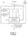
- an apparatus 1000 for encoding an audio signal 105 within such an analysis-by-synthesis implementation is illustrated.
- the parameter extractor 920 of the apparatus 1000 for encoding may be configured for determining from the plurality 117-1 of different spectral domain patching algorithm the selected patching algorithm.
- the selected patching algorithm may be based on a comparison of the audio signal 105 or a signal derived from the audio signal 105 with the plurality 1005 of bandwidth extended signals having been obtained by performing the plurality 117-1 of patching algorithms in the spectral domain and manipulating a modified spectral representation 125 of a time portion of the audio signal 105.
- the comparison may, for example, be carried out by a patching algorithm selection unit 1010 by calculating spectral flatness measure (SFM) parameters (SFM 1005 ) from the plurality 1005 of bandwidth extended signals and the audio signal 105 (SFM ref ), comparing the calculated SFM parameters SFM 1005 and SFM ref and selecting from the plurality 117-1 of patching algorithms a specific (optimum) patching algorithm, for which a deviation in the compared SFM parameters is minimal. Finally, the selected optimum patching algorithm may be indicated by the patching control signal 119 present at the output of the parameter extractor 920.
- SFM spectral flatness measure
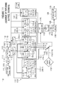
- Fig. 11 shows an overview of an embodiment for a scheme of patching in a frequency domain.
- an apparatus 1100 for generating a bandwidth extended signal such as within the bandwidth extension scheme of Fig. 2b is depicted.
- the audio signal 105 is represented by PCM (pulse code modulation) data 1101 having a frame length of 1024 samples ('frame: 1024').
- the PCM data 1101 may, for example, be a decoded low frequency signal comprising a base band derived from the encoded audio signal 935, the encoded audio signal 935 having been transmitted from an apparatus for encoding, such as the encoder 900.
- a down-sampler 1110 may be used for down-sampling the PCM data 1101 by a factor of 2, for example, to obtain a down-sampled signal 1115.
- the down-sampled signal 1115 is further supplied to an analysis windower 1120 indicated by a block denoted by "window" which may be configured to generate a plurality of overlapping windowed consecutive blocks of audio samples.
- each block from the plurality of consecutive blocks may, for example, comprise 512 audio samples.
- the overlap of the consecutive blocks of audio samples may furthermore be controlled by selecting a suitable (optimum) analysis window function from a plurality of different analysis window functions applied by the analysis windower 1120.
- the FFT processor 1130 may be configured to convert the time portion 1125 into the spectral representation 115 which may, for example, be implemented in a polar form 1135-1.
- this spectral representation 1135-1 comprises magnitude information 1135-2 and phase information 1135-3 which is further processed by a spectral domain patch generator 1141, which may correspond to the spectral domain patch generator 120 of Fig. 2a .
- the spectral domain patch generator 1141 of Fig. 11 may comprise a first patching algorithm 1141-1 denoted by "phase vocoder plus copying” corresponding to the first patching algorithm 205-1, a second patching algorithm 1143-1 denoted by "phase vocoder” corresponding to the second patching algorithm 205-2, a third patching algorithm denoted by "SBR like function” corresponding to the third patching algorithm 205-3, and a fourth patching algorithm 1147-1 denoted by "other function, e.g. non linear distortion" corresponding to the fourth patching algorithm 205-4 from the group 203 of patching algorithms as shown in Fig. 2a .
- the first patching algorithm 1141-1 comprises a single phase vocoder 1141-2 and non-harmonic copying-up functionalities 1141-3, 1141-4.
- the second patching algorithm 1143-1 which is based on a multiple phase vocoder operation comprises a first phase vocoder 1143-2, a second phase vocoder 1143-3 and a third vocoder 1143-4.
- the third patching algorithm 1145-1 comprises non-harmonic copying-up SBR functionalities performing a first copy-up operation 1145-2, a second copy-up operation 1145-3 and a third copy-up operation 1145-4.
- the fourth patching algorithm 1147-1 comprises a non linear distortion functionality.
- the sub-components of the patching algorithm blocks 1141-1, 1143-1, 1145-1, 1147-1 may correspond to those of the blocks 205-1, 205-2, 205-3, 205-4 of Fig. 2a .
- the symbol ⁇ ('xover band') may correspond to the crossover frequency (f x ).
- a patch selector 1150 may be used to provide a patching control signal 1155 corresponding to the patching control signal 119 for controlling the spectral domain patch generator 1141 such that at least two different spectral domain patching algorithms from the group 1141-1, 1143-1, 1145-1, 1147-1 of patching algorithms will be performed, leading to a modified spectral representation 1149 corresponding to the modified spectral representation 125.
- the modified spectral representation 1149 may (optionally) be processed by a subsequent interpolator 1160 to obtain an interpolated modified spectral representation 1165.
- the iFFT processor 1170 may be configured for converting the interpolated modified spectral representation 1165 into a modified time domain signal 1175 corresponding to the modified time domain signal 815 of Fig. 8 .
- the modified time domain signal 1175 may then be supplied to a synthesis windower 1180 for applying a synthesis window function to the modified time domain signal 1175 to obtain a modified windowed time domain signal 1185.
- the synthesis window function is matched to the analysis window function such that the effect of applying the analysis window function is compensated for by applying the synthesis window function.
- an output signal 1195 may be obtained which has the same overlap characteristic as the original (down-sampled) signal 1115.
- the output signal 1195 provided by the apparatus 1100 may further be processed starting from the high frequency reconstruction manipulator 130 as shown in Fig. 1a to finally obtain a replicated signal extended in bandwidth.
- Fig. 11 all different patching algorithms are carried out in the same domain, for instance in the frequency domain.
- the domain can be QMF domain as it is done in SBR or any other domain, such as Fourier transposed.
- the actual patch data generation can be carried out in a different domain. In that case, the entire patching, is however, always carried out in the same domain.
- a speech source model as used in speech bandwidth extension can be chosen for speech signals, while a stationary source model can be adopted for stationary music.
- transients may have their own model for the patching.
- the patching methods can be selected among a simple copy operation of neighbored frequency sections, a phase-vocoder based harmonic transposition scheme, and a phase-vocoder based harmonic transposition scheme which includes copying of neighbored frequency sections.
- the present invention has been described in the context of block diagrams where the blocks represent actual or logical hardware components, the present invention can also be implemented by a computer-implemented method. In the latter case, the blocks represent corresponding method steps where these steps stand for the functionalities performed by corresponding logical or physical hardware blocks.
- the inventive method can be implemented in hardware or in software.
- the implementation can be performed using a digital storage medium, in particular a disk, a DVD or a CD having electronically, readable control signals stored thereon, which cooperate with programmable computer systems, such that the inventive methods are performed.
- the present invention can therefore be implemented as a computer program product, with a program stored on a machine-readable carrier, the program code being operated for performing the inventive methods when the computer program product runs on a computer.
- the inventive methods are, therefore, a computer program having a program code for performing at least one of the inventive methods when the computer program runs on a computer.
- the inventive encoded audio signal can be stored on any machine-readable storage medium, such as a digital storage medium.
- Embodiments of the present invention allow the bandwidth extension to take into account sound, hardware, and signal characteristics for the patching process.
- the decision for the best suited patching can be done within an open or a closed loops. Therefore, the restitution quality can be controlled and enhanced.
- the presented concept has also the advantage that a smooth transition between the different patching algorithms can be reached easily, permitting a fast and accurate adaption of the bandwidth extension based upon the signal.
Abstract
An apparatus for generating a synthesis audio signal using a patching control signal comprises a first converter, a spectral domain patch generator, a high frequency reconstruction manipulator and a combiner. The first converter is configured for converting a time portion of an audio signal into a spectral representation. The spectral domain patch generator is configured for performing a plurality of different spectral domain patching algorithms, wherein each patching algorithm generates a modified spectral representation comprising spectral components in an upper frequency band derived from corresponding spectral components in a core frequency band of the audio signal. The spectral domain patch generator is furthermore configured to select a first spectral domain patching algorithm from the plurality of patching algorithms for a first time portion and a second spectral domain patching algorithm from the plurality of patching algorithm for a second different time portion in accordance with the patching control signal to obtain the modified spectral representation. The high frequency reconstruction manipulator is configured for manipulating the modified spectral representation or a signal derived from the modified spectral representation in accordance with a spectral band replication parameter to obtain a bandwidth extended signal. Finally, the combiner is configured for combining the audio signal having spectral components in the core frequency band or a signal derived from the audio signal with the bandwidth extended signal to obtain the synthesis audio signal.
Description
- The present invention relates to audio signal processing, and in particular, to an apparatus and a method for generating a synthesis audio signal, an apparatus and a method for encoding an audio signal and an encoded audio signal.
- Storage or transmission of audio signals is often subject to strict bit rate constraints. These constraints are usually overcome by an intermediate coding of the signal. In the past, coders were forced to drastically reduce the transmitted audio bandwidth when only a very low bit rate was available. Modem audio codecs are able to code wide-band signals by using bandwidth extension (BWE) methods, as described in M. Dietz, L. Liljeryd, K. Kjörling and O. Kunz, "Spectral Band Replication, a novel approach in audio coding" in 112th AES Convention, Munich, May 2002; S. Meltzer, R. Böhm and F. Henn, "SBR enhanced audio codecs for digital broadcasting such as "Digital Radio Mondiale" (DRM)," in 112th AES Convention, Munich, May 2002; T. Ziegler, A. Ehret, P. Ekstrand and M. Lutzky, "Enhancing mp3 with SBR: Features and Capabilities of the new mp3PRO Algorithm," in 112th AES Convention, Munich, May 2002; International Standard ISO/IEC 14496-3:2001/FPDAM 1, "Bandwidth Extension," ISO/IEC, 2002. Speech bandwidth extension method and apparatus
Vasu Iyengar et al. US Patent 5,455,888 ; E. Larsen, R. M. Aarts, and M. Danessis. Efficient high-frequency bandwidth extension of music and speech. In AES 112th Convention, Munich, Germany, May 2002; R.M. Aarts, E. Larsen, and O. Ouweltjes. A unified approach to low-and high frequency bandwidth extension. In AES 115th Convention, New York, USA, October 2003; K. Käyhkö. A Robust Wideband Enhancement for Narrowband Speech Signal. Research Report, Helsinki University of Technology, Laboratory of Acoustics and Audio Signal Processing, 2001; E. Larsen and R.M. Aarts. Audio Bandwidth Extension - Application to psychoacoustics, Signal Processing and Loudspeaker Design. John Wiley & Sons, Ltd, 2004; E. Larsen, R.M. Aarts, and M. Danessis. Efficient high-frequency bandwidth extension of music and speech. In AES 112th Convention, Munich, Germany, May 2002; J. Makhoul. Spectral Analysis of Speech by Linear Prediction. IEEE Transactions of Audio and Electroacoustics, AU-21(3), June 1973; United States Patent Application08/951,029, Ohmori, et al . Audio band width extending system and method; United States Patent6895375, Malah, D & Cox, R.V. : System for bandwidth extension of Narrow-band speech, and Frederik Nagel, Sascha Disch, "A harmonic bandwidth extension method for audio codecs," ICASSP International Conference on Acoustics, Speech and Signal Processing, IEEE CNF, Taipei, Taiwan, April 2009. - These algorithms rely on a parametric representation of the high-frequency content (HF). This representation is generated from the low-frequency part (LF) of the decoded signal by means of transposition into the HF spectral region ("patching") and application of a parameter driven post processing.
- In the art, methods of bandwidth extension such as spectral band replication (SBR) are used as an efficient method to generate high frequency signals in an HFR (high frequency reconstruction) based codec.
- The spectral band replication (SBR), as described in M Dietz, L. Liljeryd, K. Kj6rling and O. Kunz, "Spectral Band Replication, a novel approach in audio coding" in 112th AES Convention, Munich, May 2002, uses a quadrature mirror filterbank (QMF) for generating the HF-information. With the so-called "patching", lower QMF band signals are copied into higher QMF bands, leading to a replication of the information of the LF part in the HF part. The generated HF part is afterwards adapted to the original HF part with the help of parameters that adjust the spectral envelope and the tonality.
- In SBR, as standardized in HE-AAC, all operations, which include the patching by means of simply copying, are always carried out inside the QMF-domain. However, other different patching methods can be carried out in different domains such as the FFT domain or the time domain. One might imagine to enabling SBR to alternatively choose a patching algorithm which operates either in the FFT domain or in the time domain, and needs an additional transformation for feeding the QMF analysis step.
- In plain SBR, only one patching algorithm is available that takes into account neither needs of special hard-or software nor signal characteristics. Hence, SBR is not able to adapt the patching algorithm. One might imagine to simply choose between two distinct patching algorithms. Since the two patching methods work in different domains, the transition areas are prone to produce blocking artifacts, which makes fine-grain switching between both methods practically impossible.
-
WO 98/57436 -
WO 02/052545 - It is an object of the present invention to provide a concept for generating a synthesis audio signal enabling an improved quality and allowing for an efficient implementation.
- This object is achieved by an apparatus for generating a synthesis audio signal according to
claim 1, an apparatus for encoding an audio signal according toclaim 10, a method for generating according toclaim 12, a method for encoding according to claim 13, an encoded audio signal according to claim 14 or a computer program according to claim 15. - The present invention is based on the basic idea that the just-mentioned improved quality and/or efficient implementation may be achieved when a time portion of an audio signal is converted into a spectral representation before performing a plurality of different spectral domain patching algorithms, wherein each patching algorithm generates a modified spectral representation comprising spectral components in an upper frequency band derived from corresponding spectral components in a core frequency band of the audio signal, and selecting a first spectral domain patching algorithm from the plurality of patching algorithms for a first time portion and a second spectral domain patching algorithm from the plurality of patching algorithms for a second different time portion in accordance with a patching control signal to obtain the modified spectral representation. By this measure, a reduced quality and/or flexibility due to a switching between two patching algorithms in different domains may be prevented and therefore the processing may be less complex while maintaining the perceptual quality.
- According to an embodiment of the present invention, an apparatus for generating a synthesis audio signal using a patching control signal comprises a first converter, a spectral domain patch generator, a high frequency reconstruction manipulator and a combiner. The first converter is configured for converting a time portion of an audio signal into a spectral representation. The spectral domain patch generator is configured for performing a plurality of different spectral domain patching algorithms, wherein each patching algorithm generates a modified spectral representation comprising spectral components in an upper frequency band derived from corresponding spectral components in a core frequency band of the audio signal. The spectral domain patch generator is furthermore configured to select a first spectral domain patching algorithm from the plurality of patching algorithms for a first time portion and a second spectral domain patching algorithm from the plurality of patching algorithms for a second different time portion in accordance with the patching control signal to obtain the modified spectral representation. The high frequency reconstruction manipulator is configured for manipulating the modified spectral representation or a signal derived from the modified spectral representation in accordance with a spectral band replication parameter to obtain a bandwidth extended signal. The combiner is configured for combining the audio signal having spectral components in the core frequency band or a signal derived from the audio signal with the bandwidth extended signal to obtain the synthesis audio signal.
- According to another embodiment of the present invention, an apparatus for encoding an audio signal comprises a core encoder, a parameter extractor and a parameter calculator. The audio signal comprises a core frequency band and an upper frequency band. The core encoder is configured for encoding the audio signal within the core frequency band. The parameter extractor is configured for extracting a patching control signal from the audio signal, the patching control signal indicating a selected patching algorithm from a plurality of different spectral domain patching algorithm, the selected patching algorithm to be performed in a spectral domain for generating a synthesis audio signal in a bandwidth extension decoder. The parameter calculator is configured for calculating the spectral band replication parameter from the upper frequency band.
- According to another embodiment, an encoded audio signal data stream comprises an encoded audio signal encoded within a core frequency band, a patching control signal, the patching control signal indicating a selected patching algorithm from a plurality of different spectral domain patching algorithms, the selected patching algorithm to be performed in the spectral domain for generating a synthesis audio signal in a bandwidth extension decoder and a spectral band replication parameter calculated from an upper frequency band of the audio signal.
- Therefore, embodiments of the present invention relate to a concept for switching between at least two different spectral domain patching algorithms from a group of patching algorithms in the spectral domain. The group of patching algorithms may comprise a first patching algorithm comprising a harmonic transposition based on a single phase vocoder and non-harmonic copying-up SBR functionalities, a second patching algorithm comprising a harmonic transposition based on a multiple phase vocoder, a third patching algorithm comprising non-harmonic copying-up SBR functionalities and a fourth patching algorithm comprising a non-linear distortion. Furthermore, the bandwidth extension may be performed such that the bandwidth extended signal comprises the upper frequency band having a maximum frequency of at least four times the crossover frequency in the core frequency band.
- As a result, by switching between the at least two different patching algorithms in the spectral domain, a reduced complexity at the same perceptual quality may be achieved such as within a bandwidth extension scenario.
- Further embodiments of the present invention relate to an apparatus not comprising a time/frequency transformer for transforming a time domain signal derived from the modified spectral representation into the spectral domain. Therefore, embodiments allow that the high frequency reconstruction manipulator may be operative on the modified spectral representation directly without requiring a further transform (e.g. a QMF analysis) from the time domain to the spectral domain such as in case of a combined patching/further processing approach being operative in different domains.
- Further embodiments of the present invention relate to a parameter extractor which is configured for determining from the plurality of different spectral domain patching algorithms a selected patching algorithm. Here, the selected patching algorithm is based on a comparison of the audio signal or a signal derived from the audio signal with a plurality of bandwidth extended signals having been obtained by performing the plurality of patching algorithms in the spectral domain and manipulating a modified spectral representation of a time portion of the audio signal. Therefore, embodiments provide a method of selecting the optimal patching algorithm for generating a synthesis audio signal in a bandwidth extension decoder.
- Control parameters may be used to decide which patching is the most appropriate. To achieve this, an analysis-by-synthesis stage can be used; i.e. all patches can be applied and the best according to an objective is chosen. In the preferred mode of the invention, the objective is to get the best perceptual quality of the restitution. In alternative modes, an objective function has to be optimized. For example, the objective may be to preserve the spectral flatness of the original HFs as close as possible.
- On the one hand, the patching selection can be done only at the encoder by considering the original signal, the synthesized signal or the both of them. The decision (patching control signal) is then transmitted to the decoder. On the other hand, the selection may be performed synchronously at the encoder and decoder sides considering only the core bandwidth of the synthesized signal. The latter method does not need to generate additional side-information.
- In the following, embodiments of the present invention are explained with reference to the accompanying drawings, in which:
- Fig. 1a
- shows a block diagram of an embodiment of an apparatus for generating a synthesis audio signal using a patching control signal;
- Fig. 1b
- shows a block diagram of an implementation of a spectral domain patch generator of
Fig. 1a ; - Fig. 2a
- shows a block diagram of a further embodiment of an apparatus for generating a synthesis audio signal;
- Fig. 2b
- shows a schematic illustration of a bandwidth extension scheme;
- Fig. 3
- shows a schematic illustration of an exemplary first patching algorithm;
- Fig. 4
- shows a schematic illustration of an exemplary second patching algorithm;
- Fig. 5
- shows a schematic illustration of an exemplary third patching algorithm;
- Fig. 6
- shows a schematic illustration of an exemplary fourth patching algorithm;
- Fig. 7
- shows a block diagram of an embodiment of
Fig. 1a without a time/frequency transformer placed after the spectral domain patch generator; - Fig. 8
- shows a block diagram of an embodiment of
Fig. 1a with a second converter (frequency/time converter); - Fig. 9
- shows a block diagram of an embodiment of an apparatus for encoding an audio signal;
- Fig. 10
- shows a block diagram of a further embodiment of an apparatus for encoding an audio signal; and
- Fig. 11
- shows an overview of an embodiment for a scheme of patching in a frequency domain.
-
Fig. 1a shows a block diagram of anapparatus 100 for generating asynthesis audio signal 145 using apatching control signal 119 according to an embodiment of the present invention. Theapparatus 100 comprises afirst converter 110, a spectraldomain patch generator 120, a highfrequency reconstruction manipulator 130 and acombiner 140. Thefirst converter 110 is configured for converting a time portion of anaudio signal 105 into aspectral representation 115. The spectraldomain patch generator 120 is configured for performing a plurality 117-1 of different spectral domain patching algorithms, wherein each patching algorithm generates a modifiedspectral representation 125 comprising spectral components in an upper frequency band derived from corresponding spectral components in a core frequency band of theaudio signal 105. As shown inFig. 1b the spectraldomain patch generator 120 may be configured to select a first spectral domain patching algorithm 117-2 from the plurality 117-1 of patching algorithms for a first time portion 107-1 and a second spectral domain patching algorithm 117-3 from the plurality 117-1 of patching algorithms for a second different time portion 107-2 in accordance with the patchingcontrol signal 119 to obtain the modifiedspectral representation 125. - The high
frequency reconstruction manipulator 130 is configured for manipulating the modifiedspectral representation 125 or a signal derived from the modifiedspectral representation 125 in accordance with a spectralband replication parameter 127 to obtain a bandwidth extendedsignal 135. The signal derived from the modifiedspectral representation 125 may, for example, be a signal in a QMF domain having been obtained after applying a QMF analysis to a modified time domain signal being based on the modifiedspectral representation 125. Thecombiner 140 is configured for combining theaudio signal 105 having spectral components in the core frequency band or a signal derived from theaudio signal 105 with the bandwidth extendedsignal 135 to obtain thesynthesis audio signal 145. Here, the signal derived from theaudio signal 105 may, for example, be a decoded low frequency signal having been obtained after decoding an encoded audio signal within the core frequency band. - As can be seen in
Fig. 1a , the spectraldomain patch generator 120 of theapparatus 100 is implemented to be operative in a spectral domain and not in a time domain. -
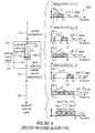
Fig. 2a shows a block diagram of a further embodiment of anapparatus 200 for generating thesynthesis audio signal 145. Here, the components of theapparatus 200 ofFig. 2a , which are the same as in theapparatus 100 ofFig. 1a , are omitted and not shown or described again. In the embodiment as shown inFig. 2a , the spectraldomain patch generator 120 of theapparatus 200 is configured for performing at least two different spectral domain patching algorithms from agroup 203 of patching algorithms in the spectral domain. Thegroup 203 of patching algorithms comprises a first patching algorithm 205-1 comprising a harmonic transposition based on a single phase vocoder and non-harmonic copying-up SBR functionalities, a second patching algorithm 205-2 comprising a harmonic transposition based on a multiple phase vocoder, a third patching algorithm 205-3 comprising non-harmonic copying-up SBR functionalities and a fourth patching algorithm 205-4 comprising a non-linear distortion. - As shown in
Fig. 2b , theapparatus 200 may be adapted for performing a bandwidth extension such that the bandwidth extendedsignal 135 comprises theupper frequency band 220 having amaximum frequency 225 of at least four times thecrossover frequency 215 in thecore frequency band 210. In the context of SBR, the typical value of thecrossover frequency 215 defined as the highest frequency of thecore frequency band 210 may, for example, be in a range below 4 kHz, 5 kHz or 6 kHz. Consequently, themaximum frequency 225 of theupper frequency band 220 may, for example, be about 16 kHz, 20 kHz or 24 kHz. -
Fig. 3 shows a schematic illustration of an exemplary first patching algorithm 205-1. In particular, the spectraldomain patch generator 120 is configured for performing a selected patching algorithm from the at least two different spectral domain patching algorithms, the selected patching algorithm comprising the first patching algorithm 205-1. The first patching algorithm 205-1 comprises a harmonic transposition based on asingle phase vocoder 305 comprising a bandwidth extension factor (σ) of two controlling a transform from asource frequency band 310 extracted from thecore frequency band 210 into a first target frequency band 310'. Here, phases of the spectral components in thesource frequency band 310 are multiplied by the bandwidth extension factor (σ) such that the firsttarget frequency band 310 has frequencies ranging from the crossover frequency (fx) to twice the crossover frequency (fx). The first patching algorithm 205-1 further comprises non-harmonic copying-upSBR functionalities 315 for transforming spectral components in the first target frequency band 310' into a second target frequency band 320' by a first copying-up such that the second target frequency band 320' has frequencies ranging from twice the crossover frequency (fx) to three times the crossover frequency (fx) and for further transforming spectral components in the second target frequency band 320' into a third target frequency band 330' by a second copying-up such that the third target frequency band 330' has frequencies ranging from three times the crossover frequency (fx) to four times the crossover frequency (fx) included in theupper frequency band 220, theupper frequency band 220 comprising the first 310', second 320' and third 330' target frequency band. In particular, as shown inFig. 3 , the bandwidth extendedsignal 135 comprises theupper frequency band 220 generated from thecore frequency band 210, wherein theupper frequency band 220 has a maximum frequency of four times the crossover frequency (fx). -
Fig. 4 shows a schematic illustration of an exemplary second patching algorithm 205-2. Here in particular, the spectraldomain patch generator 120 is configured for performing a selected patching algorithm from the at least two different spectral domain patching algorithms, the selected patching algorithm comprising the second patching algorithm 205-2. The second patching algorithm 205-2 comprises a harmonic transposition based on amultiple phase vocoder 405 comprising a first bandwidth extension factor (σ1) of 2 controlling a transform from a firstsource frequency band 410 extracted from thecore frequency band 210 into a first target frequency band 410'. Here, phases of the spectral components in the firstsource frequency band 410 are multiplied by the first bandwidth extension factor (σ1) such that the first target frequency band 410' has frequencies ranging from the crossover frequency (fx) to twice the crossover frequency (fx). The second patching algorithm 205-2 further comprises a second bandwidth extension factor (σ2) of 3 controlling a transform from a second source frequency band 420-1, 420-2 extracted from thecore frequency band 210 into a secondtarget frequency band 420', 420". Here, phases of the spectral components in the second source frequency band 420-1, 420-2 are multiplied by the second bandwidth extension factor (σ2) such that the secondtarget frequency band 420', 420" has frequencies ranging from twice the crossover frequency (fx) to three times the crossover frequency (fx) or ranging from the crossover frequency (fx) to three times the crossover frequency (fx), respectively. Finally, the second patching algorithm 205-2 further comprises a third bandwidth extension factor (σ3) of 4 controlling a transform from a third source frequency band 430-1, 430-2 extracted from thecore frequency band 210 into a thirdtarget frequency band 430', 430". Here, phases of the spectral components in the third source frequency band 430-1, 430-2 are multiplied by the third bandwidth extension factor (σ3) such that the thirdtarget frequency band 430', 430" has frequencies ranging from three times the crossover frequency (fx) to four times the crossover frequency (fx) or ranging from the crossover frequency (fx) to four times the crossover frequency (fx) included in theupper frequency band 220, respectively. As in the first patching algorithm 205-1 shown inFig. 3 , theupper frequency band 220 of the bandwidth extendedsignal 135 comprises the first 410', second 420', 420" and third 430', 430" target frequency band having a maximum frequency of four times the crossover frequency (fx). -
Fig. 5 shows a schematic illustration of an exemplary third patching algorithm 205-3. In the embodiment ofFig. 5 , the spectraldomain patch generator 120 is configured for performing a select patching algorithm from the at least two different spectral domain patching algorithms, the selected patching algorithm comprising the third patching algorithm 205-3. The third patching algorithm 205-3 comprises non-harmonic copying-upSBR functionalities 505 for transforming spectral components in asource frequency band 510 being thecore frequency band 210 into a target frequency band 510' by a first copying-up such that the first target frequency band 510' has frequencies ranging from the crossover frequency (fx) to twice the crossover frequency (fx). Spectral components in the first target frequency band 510' are further transformed into a second target frequency band 520' by a second copying-up such that the second target frequency band 520' has frequencies ranging from twice the crossover frequency (fx) to three times the crossover frequency (fx). Finally, spectral components in the second target frequency band 520' are further transformed into a third target frequency band 530' by a third copying-up such that the third target frequency band 530' has frequencies ranging from three times the crossover frequency (fx) to four times the crossover frequency (fx) included in theupper frequency band 220. Again, theupper frequency band 220 of the bandwidth extendedsignal 135 comprises the first 510', second 520' and third 530' target frequency band having a maximum frequency of four times the crossover frequency (fx). -
Fig. 6 shows a schematic illustration of an exemplary fourth patching algorithm 205-4. In the embodiment ofFig. 6 , the spectraldomain patch generator 120 is configured for performing a selected patching algorithm from the at least two different spectral domain patching algorithms, the selected patching algorithm comprising the fourth patching algorithm 205-4. Here, the fourth patching algorithm 205-4 comprises a non-linear distortion for generating the spectral components in theupper frequency band 220 having frequencies ranging from the crossover frequency (fx) to four times the crossover frequency (fx). - Generally, in the embodiments of
Figs. 3-6 as described above, the spectral domain patching algorithms 205-1; 205-2; 205-3; 205-4 are performed with the spectraldomain patch generator 120 being configured for transforming a spectral component in aninitial band 310, 310', 320'; 410, 420-1, 420-2, 430-1, 430-2; 510, 510', 520' derived from thecore frequency band 210 or an upper frequency band not included in thecore frequency band 210 into a target spectral component in theupper frequency band 220 such that the target spectral component is different for each spectral domain patching algorithm. - In particular, the spectral
domain patch generator 120 may comprise a band pass filter for extracting the initial band from thecore frequency band 210 or theupper frequency band 220, wherein a band pass characteristic of the band pass filter may be selected such that the initial band will be transformed into a corresponding target frequency band 310', 320', 330'; 410', 420', 420", 430', 430"; 510', 520', 530' as shown inFigs. 3-6 . - The different spectral domain patching algorithms 205-1; 205-2; 205-3; 205-4 may be performed in accordance with a required performance such as within the bandwidth extension scheme of
Fig. 2b . - Specifically, by employing a single or multiple phase vocoder as shown for example in
Fig. 3 orFig. 4 , respectively, the frequency structure is harmonically correctly extended to the high frequency domain, because the base band (e.g. the core frequency band 210) is spectrally spread by an even multiple (e.g. σ1 = 2, σ2 = 3, σ3 = 4), and because spectral components in the base band are combined with the additional generated spectral components. - A phase vocoder based patching algorithm may be advantageous if the base band is already strongly limited in bandwidth, for example, by using only a very low bit rate. Hence, the reconstruction of the upper frequency components already starts at a relatively low frequency. The typical crossover frequency is, in this case, less than about 5 KHz (or even less than 4 KHz). In this region, the human ear is very sensitive to dissonances due to incorrectly positioned harmonics. This can result in the impression of "unnatural" tones. In addition, spectrally closely spaced tones (with the spectral dissonance of about 30 Hz to 300 Hz) are perceived as rough tones. The harmonic continuation of the frequency structure of the base band avoids these incorrect and unpleasant hearing impressions.
- Furthermore, by employing non-harmonic copying-up SBR functionalities as shown, for example in
Fig. 5 , spectral regions may be sub-band wise copied to a higher frequency region or into the frequency region to be replicated. Also copying relies on the observation, which is true for all patching methods, that the spectral properties of the higher frequency signals are similar in many respects to the properties of the base band signals. There are only a very few deviations from each other. In addition, the human ear is typically not very sensitive at high frequency (typically starting at about 5 KHz), especially with respect to a non-precise spectral mapping. In fact, this is the key idea of the spectral band replication in general. Copying in particular, comprises the advantage that it is easy and fast to implement. This patching algorithm also has a high flexibility with respect to the borders of the patch, since the copying of the spectrum may be performed at any sub-band border. - Finally, the patching algorithm of non linear distortion (see, e.g.
Fig. 6 ) may comprise a generation of harmonics by clipping, limiting, squaring, etc. If for example, a spread signal is spectrally very thinly occupied (e.g. after applying the above mentioned phase vocoder patching algorithm), it is possible that the spread spectrum can optionally be additively supplemented by a distorted signal in order to avoid unwanted frequency holes. - It is to be noted that besides the above mentioned patching algorithms from the
group 203 of patching algorithms (seeFig. 2a ), other patching algorithms within the spectral domain such as a spectral mirroring, may be performed. - In the embodiment of
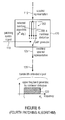
Fig. 7 , anapparatus 700, which may correspond to theapparatus 100 ofFig. 1a , is shown not comprising a time/frequency transformer for transforming a time domain signal derived from the modifiedspectral representation 125 into the spectral domain. This means that in this case, the highfrequency reconstruction manipulator 130 will receive as its input the modifiedspectral representation 125 and not a frequency domain signal obtained from such a time/frequency transformer. - The described configuration may be advantageous, because in this case, the further processing of the modified
spectral representation 125 performed by the highfrequency reconstruction manipulator 130 can readily take place in the same domain (e.g. the FFT or QMF domain) as the patching algorithm performed by the spectraldomain patch generator 120 is operative in. Therefore, a further transform between different domains such as a transform from the time domain to the spectral domain (e.g. a QMF analysis) will not be required, leading to an easier implementation. - In the embodiment of
Fig. 8 , anapparatus 800 is shown further comprising asecond converter 810 for converting the modifiedspectral representation 125 into the time domain. Again, the components of theapparatus 800 ofFig. 8 , which may correspond to those of theapparatus 100 ofFig. 1a , are omitted. As shown inFig. 8 , thesecond converter 810 may be adapted to apply a synthesis matched to an analysis applied by thefirst converter 110. Here, thefirst converter 110 is configured to perform a conversion having afirst conversion length 111, while thesecond converter 810 is configured to perform a conversion having a second conversion length. In particular, the second conversion length may depend on a bandwidth extension characteristic in that a ratio of the maximum frequency (fmax) in theupper frequency band 220 and the crossover frequency (fx) in thecore frequency band 210 and thefirst conversion length 111 is accounted for. - In embodiments of the present invention, the
first converter 110 may, for example, be implemented to perform a fast Fourier transform (FFT), a short-time Fourier transform (STFT), a discrete Fourier transform (DFT) or a QMF analysis, while thesecond converter 810 may, for example, be implemented to perform an inverse fast Fourier transform (IFFT), an inverse short-time Fourier transform (ISTFT), an inverse discrete Fourier transform (IDFT) or a QMF synthesis. - Specifically, the second conversion length may be chosen such that it will be equal to the ratio fmax/fx multiplied by the
first conversion length 111. In this way, the second conversion length or frequency resolution applied by thesecond converter 810 will readily be adapted to the bandwidth extension characteristic of the bandwidth extension scheme as shown inFig. 2b . This is because the bandwidth extension characteristic is essentially governed by the above ration (fmax/fx) corresponding to a higher effective sampling rate according to Nyquist's principle. -
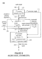
Fig. 9 shows a block diagram of an embodiment of an apparatus 900 for encoding anaudio signal 105. Theaudio signal 105 comprises acore frequency band 210 and anupper frequency band 220. In particular, the apparatus 900 for encoding comprises acore encoder 910, aparameter extractor 920 and aparameter calculator 930. Thecore encoder 910 is configured for encoding theaudio signal 105 within thecore frequency band 210 to obtain an encodedaudio signal 915 encoded within thecore frequency band 210. Furthermore, theparameter extractor 920 is configured for extracting a patching control signal 119 from theaudio signal 105, the patchingcontrol signal 119 indicating a selected patching algorithm from a plurality 117-1 of different spectral domain patching algorithms. Specifically, the selected patching algorithm may be performed in a spectral domain for generating the synthesis audio signal in a bandwidth extension decoder. Finally, theparameter calculator 930 is configured for calculating aSBR parameter 127 from theupper frequency band 220. TheSBR parameter 127 calculated from theupper frequency band 220, the patchingcontrol signal 119 indicating the selected patching algorithm and the encodedaudio signal 915 encoded within thecore frequency band 210 may constitute an encodedaudio signal 935 to be stored or transmitted within a bit stream. - In the embodiment of
Fig. 9 , theparameter extractor 920 may be configured for analyzing theaudio signal 105 or a signal derived from theaudio signal 105 to determine the patchingcontrol signal 119 based on a signal characteristic of the analyzed signal. For example, the patchingcontrol signal 119 may indicate a first patching algorithm for a first time portion 107-1 of the analyzed signal being characterized as 'speech' and a second patching algorithm for a second time portion 107-2 of the analyzed signal being characterized as 'stationary music'. - Accordingly, in case of a speech signal, a processing based on a speech source model or an information generation model such as within a LPC (linear predictive coding) domain may be used, while in case of stationary music, a stationary source model or an information sink model may be used. While in the former case, the human speech/sound generation system generating sound is described, in the latter case, the human auditory system receiving sound is described.
- In addition, a signal dependent processing scheme may be implemented by switching between a harmonic transposition for a time portion comprising a transient event and a non-harmonic copying-up operation for a time portion not comprising a transient event.
- The above procedure corresponding to an open loop is based on a direct analysis of the
audio signal 105 or a signal derived from theaudio signal 105 with respect to its signal characteristic. Alternatively, theparameter extractor 920 may also be operative in a closed loop corresponding to an "analysis-by-synthesis" implementation. - In the embodiment of
Fig. 10 , anapparatus 1000 for encoding anaudio signal 105 within such an analysis-by-synthesis implementation is illustrated. Specifically, theparameter extractor 920 of theapparatus 1000 for encoding may be configured for determining from the plurality 117-1 of different spectral domain patching algorithm the selected patching algorithm. Here, the selected patching algorithm may be based on a comparison of theaudio signal 105 or a signal derived from theaudio signal 105 with theplurality 1005 of bandwidth extended signals having been obtained by performing the plurality 117-1 of patching algorithms in the spectral domain and manipulating a modifiedspectral representation 125 of a time portion of theaudio signal 105. The comparison may, for example, be carried out by a patchingalgorithm selection unit 1010 by calculating spectral flatness measure (SFM) parameters (SFM1005) from theplurality 1005 of bandwidth extended signals and the audio signal 105 (SFMref), comparing the calculated SFM parameters SFM1005 and SFMref and selecting from the plurality 117-1 of patching algorithms a specific (optimum) patching algorithm, for which a deviation in the compared SFM parameters is minimal. Finally, the selected optimum patching algorithm may be indicated by the patchingcontrol signal 119 present at the output of theparameter extractor 920. -
Fig. 11 shows an overview of an embodiment for a scheme of patching in a frequency domain. In particular, anapparatus 1100 for generating a bandwidth extended signal such as within the bandwidth extension scheme ofFig. 2b is depicted. In the embodiment ofFig. 11 , theaudio signal 105 is represented by PCM (pulse code modulation) data 1101 having a frame length of 1024 samples ('frame: 1024'). The PCM data 1101 may, for example, be a decoded low frequency signal comprising a base band derived from the encodedaudio signal 935, the encodedaudio signal 935 having been transmitted from an apparatus for encoding, such as the encoder 900. Next, a down-sampler 1110 may be used for down-sampling the PCM data 1101 by a factor of 2, for example, to obtain a down-sampledsignal 1115. The down-sampledsignal 1115 is further supplied to ananalysis windower 1120 indicated by a block denoted by "window" which may be configured to generate a plurality of overlapping windowed consecutive blocks of audio samples. Here, each block from the plurality of consecutive blocks may, for example, comprise 512 audio samples. In addition, a first time distance between two consecutive blocks of audio samples may, for example, be adjusted to correspond to 64 samples as denoted by "Inc = 64". The overlap of the consecutive blocks of audio samples may furthermore be controlled by selecting a suitable (optimum) analysis window function from a plurality of different analysis window functions applied by theanalysis windower 1120. Atime portion 1125 of theaudio signal 105, which may correspond to a consecutive block from the plurality of consecutive blocks of audio samples, is further supplied to thefirst converter 110 which may be implemented as, for example, anFFT processor 1130 having thefirst conversion length 111 of N = 512. TheFFT processor 1130 may be configured to convert thetime portion 1125 into thespectral representation 115 which may, for example, be implemented in a polar form 1135-1. In particular, this spectral representation 1135-1 comprises magnitude information 1135-2 and phase information 1135-3 which is further processed by a spectraldomain patch generator 1141, which may correspond to the spectraldomain patch generator 120 ofFig. 2a . The spectraldomain patch generator 1141 ofFig. 11 may comprise a first patching algorithm 1141-1 denoted by "phase vocoder plus copying" corresponding to the first patching algorithm 205-1, a second patching algorithm 1143-1 denoted by "phase vocoder" corresponding to the second patching algorithm 205-2, a third patching algorithm denoted by "SBR like function" corresponding to the third patching algorithm 205-3, and a fourth patching algorithm 1147-1 denoted by "other function, e.g. non linear distortion" corresponding to the fourth patching algorithm 205-4 from thegroup 203 of patching algorithms as shown inFig. 2a . - As described correspondingly in the context of
Fig. 2a before, the first patching algorithm 1141-1 comprises a single phase vocoder 1141-2 and non-harmonic copying-up functionalities 1141-3, 1141-4. Furthermore, the second patching algorithm 1143-1, which is based on a multiple phase vocoder operation comprises a first phase vocoder 1143-2, a second phase vocoder 1143-3 and a third vocoder 1143-4. Furthermore, the third patching algorithm 1145-1 comprises non-harmonic copying-up SBR functionalities performing a first copy-up operation 1145-2, a second copy-up operation 1145-3 and a third copy-up operation 1145-4. Finally, the fourth patching algorithm 1147-1 comprises a non linear distortion functionality. - Particularly, in the embodiment of
Fig. 11 , the sub-components of the patching algorithm blocks 1141-1, 1143-1, 1145-1, 1147-1 may correspond to those of the blocks 205-1, 205-2, 205-3, 205-4 ofFig. 2a . In addition, the symbol ζ ('xover band') may correspond to the crossover frequency (fx). - Moreover, a
patch selector 1150 may be used to provide apatching control signal 1155 corresponding to the patchingcontrol signal 119 for controlling the spectraldomain patch generator 1141 such that at least two different spectral domain patching algorithms from the group 1141-1, 1143-1, 1145-1, 1147-1 of patching algorithms will be performed, leading to a modifiedspectral representation 1149 corresponding to the modifiedspectral representation 125. - The modified
spectral representation 1149 may (optionally) be processed by asubsequent interpolator 1160 to obtain an interpolated modifiedspectral representation 1165. The interpolated modifiedspectral representation 1165 may then be supplied to thesecond converter 810, which may, for example, be implemented as an iFFT processor 1170 having a second conversion length of N = 2048. Here, as described correspondingly inFig. 8 , the second conversion length of N = 2048 is adjusted to be exactly four times higher than the first conversion length of N = 512. Thus, the bandwidth extension characteristic of the bandwidth extension scheme as performed with the different spectral domain patching algorithms may be accounted for, which has been explained in detail before. - The iFFT processor 1170 may be configured for converting the interpolated modified
spectral representation 1165 into a modifiedtime domain signal 1175 corresponding to the modifiedtime domain signal 815 ofFig. 8 . The modifiedtime domain signal 1175 may then be supplied to asynthesis windower 1180 for applying a synthesis window function to the modifiedtime domain signal 1175 to obtain a modified windowed time domain signal 1185. Here, the synthesis window function is matched to the analysis window function such that the effect of applying the analysis window function is compensated for by applying the synthesis window function. - Since the modified windowed time domain signal 1185 has to be sampled at a higher effective sampling rate (e.g. 32 KHz) as compared to the original sampling rate (e.g. 8 KHz) due to the bandwidth extension, the modified windowed time domain signal 1185 may finally be overlap-added in a block 1190 denoted by "overlap and add" in that a ratio of a second time distance of, for example 256 samples, denoted by "Inc = 256" applied by the block 1190 and the first time distance of, for example 64 samples, applied by the analysis windower 1120 (e.g. ratio = 4) will be equal to the ratio of the higher effective sampling rate and the original sampling rate. In this way, an output signal 1195 may be obtained which has the same overlap characteristic as the original (down-sampled)
signal 1115. The output signal 1195 provided by theapparatus 1100 may further be processed starting from the highfrequency reconstruction manipulator 130 as shown inFig. 1a to finally obtain a replicated signal extended in bandwidth. - It is to be noted that in the embodiment of
Fig. 11 , all different patching algorithms are carried out in the same domain, for instance in the frequency domain. The domain can be QMF domain as it is done in SBR or any other domain, such as Fourier transposed. The actual patch data generation can be carried out in a different domain. In that case, the entire patching, is however, always carried out in the same domain. - Additionally different source models can be associated to the patching considered in the selection. For instance, a speech source model as used in speech bandwidth extension can be chosen for speech signals, while a stationary source model can be adopted for stationary music. In the same way, as described before, transients may have their own model for the patching.
- Furthermore, by means of overlapping analysis and synthesis windows for time-frequency transposition, smooth transitions between different patching schemes are guaranteed. Alternatively, special windows for analysis and synthesis can be used in order to make lower overlap possible.
- In summary, in the
Fig. 11 embodiment, the patching methods can be selected among a simple copy operation of neighbored frequency sections, a phase-vocoder based harmonic transposition scheme, and a phase-vocoder based harmonic transposition scheme which includes copying of neighbored frequency sections. - Although the present invention has been described in the context of block diagrams where the blocks represent actual or logical hardware components, the present invention can also be implemented by a computer-implemented method. In the latter case, the blocks represent corresponding method steps where these steps stand for the functionalities performed by corresponding logical or physical hardware blocks.
- The described embodiments are merely illustrative for the principles of the present invention. It is understood that modifications and variations of the arrangements and the details described herein will be apparent to others skilled in the art. It is the intent, therefore, to be limited only by the scope of the impending patent claims, and not by the specific details presented by way of description and explanation of the embodiments herein.
- Dependent on certain implementation requirements of the inventive method, the inventive method can be implemented in hardware or in software. The implementation can be performed using a digital storage medium, in particular a disk, a DVD or a CD having electronically, readable control signals stored thereon, which cooperate with programmable computer systems, such that the inventive methods are performed. Generally, the present invention can therefore be implemented as a computer program product, with a program stored on a machine-readable carrier, the program code being operated for performing the inventive methods when the computer program product runs on a computer. In other words, the inventive methods are, therefore, a computer program having a program code for performing at least one of the inventive methods when the computer program runs on a computer. The inventive encoded audio signal can be stored on any machine-readable storage medium, such as a digital storage medium.
- Embodiments of the present invention allow the bandwidth extension to take into account sound, hardware, and signal characteristics for the patching process. The decision for the best suited patching can be done within an open or a closed loops. Therefore, the restitution quality can be controlled and enhanced.
- The presented concept has also the advantage that a smooth transition between the different patching algorithms can be reached easily, permitting a fast and accurate adaption of the bandwidth extension based upon the signal.
- Most prominent applications are audio decoders, which are often implemented on handheld devices and thus operate on a battery power supply.
Claims (15)
- An apparatus (100; 200; 700; 800; 1100) for generating a synthesis audio signal (145) using a patching control signal (119; 1155), the apparatus (100; 200; 700; 800; 1100) comprising:a first converter (110; 1130) for converting a time portion (107-1; 107-2; 1125) of an audio signal (105; 1101) into a spectral representation (115: 1135-1);a spectral domain patch generator (120; 1141) for performing a plurality (117-1) of different spectral domain patching algorithms, wherein each patching algorithm generates a modified spectral representation (125; 1149) comprising spectral components in an upper frequency band (220) derived from corresponding spectral components in a core frequency band (210) of the audio signal (105; 1101), and wherein the spectral domain patch generator (120; 1141) is configured to select a first spectral domain patching algorithm (117-2) from the plurality (117-1) of patching algorithms for a first time portion (107-1) and a second spectral domain patching algorithm (117-3) from the plurality (117-1) of patching algorithms for a second different time portion (107-2) in accordance with the patching control signal (119; 1155) to obtain the modified spectral representation (125; 1149);a high frequency reconstruction manipulator (130) for manipulating the modified spectral representation (125; 1149) or a signal derived from the modified spectral representation (125; 1195) in accordance with a spectral band replication parameter (127) to obtain a bandwidth extended signal (135); anda combiner (140) for combining the audio signal (105; 1101) having spectral components in the core frequency band (210) or a signal derived from the audio signal (105; 1101) with the bandwidth extended signal (135) to obtain the synthesis audio signal (145).
- The apparatus (100; 200; 700; 800; 1100) in accordance with claim 1, in which the spectral domain patch generator (120; 1141) is implemented to be operative in a spectral domain and not in a time domain.
- The apparatus (200) in accordance with claim 1 or 2, wherein the spectral domain patch generator (120) is configured for performing at least two different spectral domain patching algorithms from a group (203) of patching algorithms in the spectral domain, the group (203) of patching algorithms comprising a first patching algorithm (205-1) comprising a harmonic transposition based on a single phase vocoder and non-harmonic copying-up spectral band replication functionalities, a second patching algorithm (205-2) comprising a harmonic transposition based on a multiple phase vocoder, a third patching algorithm (205-3) comprising non-harmonic copying-up spectral band replication functionalities and a fourth patching algorithm (205-4) comprising a non-linear distortion, the apparatus (200) being adapted for performing a bandwidth extension such that the bandwidth extended signal (135) comprises the upper frequency band (220) having a maximum frequency (225; fmax) of at least four times the crossover frequency (215; fx) in the core frequency band (210).
- The apparatus in accordance with claim 3, wherein the spectral domain patch generator (120) is configured for performing a selected patching algorithm from the at least two different spectral domain patching algorithms, the selected patching algorithm comprising the first patching algorithm (205-1), the first patching algorithm (205-1) comprising a harmonic transposition based on a single phase vocoder (305) comprising a bandwidth extension factor (σ) of two controlling a transform from a source frequency band (310) extracted from the core frequency band (210) into a first target frequency band (310'), wherein phases of the spectral components in the source frequency band (310) are multiplied by the bandwidth extension factor (σ) such that the first target frequency band (310) has frequencies ranging from the crossover frequency (fx) to twice the crossover frequency (fx), the first patching algorithm (205-1) further comprising non-harmonic copying-up spectral band replication functionalities (315) for transforming spectral components in the first target frequency band (310') into a second target frequency band (320') by a first copying-up such that the second target frequency band (320') has frequencies ranging from twice the crossover frequency (fx) to three times the crossover frequency (fx) and for further transforming spectral components in the second target frequency band (320') into a third target frequency band (330') by a second copying-up such that the third target frequency band (330') has frequencies ranging from three times the crossover frequency (fx) to four times the crossover frequency (fx) included in the upper frequency band (220), the upper frequency band (220) comprising the first (310'), second (320') and third (330') target frequency band.
- The apparatus in accordance with claim 3, wherein the spectral domain patch generator (120) is configured for performing a selected patching algorithm from the at least two different spectral domain patching algorithms, the selected patching algorithm comprising the second patching algorithm (205-2), the second patching algorithm (205-2) comprising a harmonic transposition based on a multiple phase vocoder (405) comprising a first bandwidth extension factor (σ1) of two controlling a transform from a first source frequency band (410) extracted from the core frequency band (210) into a first target frequency band (410'), wherein phases of the spectral components in the first source frequency band (410) are multiplied by the first bandwidth extension factor (σ1) such that the first target frequency band (410') has frequencies ranging from the crossover frequency (fx) to twice the crossover frequency (fx), the second patching algorithm (205-2) further comprising a second bandwidth extension factor (σ2) of three controlling a transform from a second source frequency band (420-1, 420-2) extracted from the core frequency band (210) into a second target frequency band (420', 420"), wherein phases of the spectral components in the second source frequency band (420-1, 420-2) are multiplied by the second bandwidth extension factor (σ2) such that the second target frequency band (420', 420") has frequencies ranging from twice the crossover frequency (fx) to three times the crossover frequency (fx) or ranging from the crossover frequency (fx) to three time the crossover frequency (fx), the second patching algorithm (205-2) further comprising a third bandwidth extension factor (σ3) of four controlling a transform from a third source frequency band (430-1, 430-2) extracted from the core frequency band (210) into a third target frequency band (430', 430"), wherein phases of the spectral components in the third source frequency band (430', 430") are multiplied by the third bandwidth extension factor (σ3) such that the third target frequency band (430', 430") has frequencies ranging from three times the crossover frequency (fx) to four times the crossover frequency (fx) or ranging from the crossover frequency (fx) to four times the crossover frequency (fx) included in the upper frequency band (220), the upper frequency (220) comprising the first (410'), second (420', 420") and third (430', 430") target frequency band.
- The apparatus in accordance with claim 3, wherein the spectral domain patch generator (120) is configured for performing a selected patching algorithm from the at least two different spectral domain patching algorithms, the selected patching algorithm comprising the third patching algorithm (205-3), the third patching algorithm (205-3) comprising non-harmonic copying-up spectral band replication functionalities (505) for transforming spectral components in a source frequency band (510) being the core frequency band (210) into a first target frequency band (510') by a first copying-up such that the first target frequency band (510') has frequencies ranging from the crossover frequency (fx) to twice the crossover frequency (fx), for further transforming spectral components in the first target frequency band (510') into a second target frequency band (520') by a second copying-up such that the second target frequency band (520') has frequencies ranging from twice the crossover frequency (fx) to three times the crossover frequency (fx) and for further transforming spectral components in the second target frequency band (520') into a third target frequency band (530') by a third copying-up such that the third target frequency band (530') has frequencies ranging from three times the crossover frequency (fx) to four times the crossover frequency (fx) included in the upper frequency band (220), the upper frequency band (220) comprising the first (510'), second (520') and third (530') target frequency band.
- The apparatus in accordance with claim 3, wherein the spectral domain patch generator (120) is configured for performing a selected patching algorithm from the at least two different spectral domain patching algorithms, the selected patching algorithm comprising the fourth patching algorithm (205-4), the fourth patching algorithm (205-4) comprising a non-linear distortion for generating the spectral components in the upper frequency band (220) having frequencies ranging from the crossover frequency (fx) to four times the crossover frequency (fx).
- The apparatus (700) according to one of the preceding claims, the apparatus (700) not comprising a time/frequency transformer (710) for transforming a time domain signal (705) derived from the modified spectral representation (125) into the spectral domain.
- The apparatus (800) according to one of the preceding claims, the apparatus (800) further comprising a second converter (810) for converting the modified spectral representation (125) into the time domain, wherein the second converter (810) is adapted to apply a synthesis matched to an analysis applied by the first converter (110), wherein the first converter (110) is configured to perform a conversion having a first conversion length (111), and wherein the second converter (810) is configured to perform a conversion having a second conversion length, the second conversion length depending on a bandwidth extension characteristic in that a ratio of the maximum frequency (fmax) in the upper frequency band (220) and the crossover frequency (fx) in the core frequency band (210) and the first conversion length (111) is accounted for.
- An apparatus (900; 1000) for encoding an audio signal (105), the audio signal (105) comprising a core frequency band (210) and an upper frequency band (220), the apparatus (900; 1000) comprising:a core encoder (910) for encoding the audio signal (105) within the core frequency band (210);a parameter extractor (920) for extracting a patching control signal (119) from the audio signal (105), the patching control signal (119) indicating a selected patching algorithm from a plurality (117-1) of different spectral domain patching algorithms, the selected patching algorithm to be performed in a spectral domain for generating a synthesis audio signal in a bandwidth extension decoder; anda parameter calculator (930) for calculating a spectral band replication parameter (127) from the upper frequency band (220).
- The apparatus (1000) for encoding in accordance with claim 10, wherein the parameter extractor (920) is configured for determining from the plurality (117-1) of different spectral domain patching algorithms the selected patching algorithm, the selected patching algorithm being based on a comparison of the audio signal (105) or a signal derived from the audio signal (105) with a plurality (1005) of bandwidth extended signals having been obtained by performing the plurality (117-1) of patching algorithms in the spectral domain and manipulating a modified spectral representation (125) of a time portion of the audio signal (105).
- A method (100; 200; 700; 800; 1100) for generating a synthesis audio signal (145) using a patching control signal (190; 1155), the method (100; 200; 700; 800; 1100) comprising:converting (110; 1130) a time portion (107-1; 107-2; 1125) of an audio signal (105; 1101) into a spectral representation (115; 1135-1);performing (120; 1141) a plurality (117-1) of different spectral domain patching algorithms, wherein each patching algorithm generates a modified spectral representation (125; 1149) comprising spectral components in an upper frequency band (220) derived from corresponding spectral components in a core frequency band (210) of the audio signal (105; 1101), and selecting (120; 1141) a first spectral domain patching algorithm (117-2) from the plurality (117-1) of patching algorithms for a first time portion (107-1) and a second spectral domain patching algorithm (117-3) from the plurality (117-1) of patching algorithms for a second different time portion (107-2) in accordance with the patching control signal (119; 1155) to obtain the modified spectral representation (125; 1149);manipulating (130) the modified spectral representation (125; 1149) or a signal derived from the modified spectral representation (125; 1195) in accordance with a spectral band replication parameter (127) to obtain a bandwidth extended signal (135); andcombining (140) the audio signal (105; 1101) having spectral components in the core frequency band (210) or a signal derived from the audio signal (105; 1101) with the bandwidth extended signal (135) to obtain the synthesis audio signal (145).
- A method (900; 1000) for encoding an audio signal (105), the audio signal (105) comprising a core frequency band (210) and an upper frequency band (220), the method (900; 1000) comprising:encoding (910) the audio signal (105) within the core frequency band (210);extracting (920) a patching control signal (119) from the audio signal (105), the patching control signal (119) indicating a selected patching algorithm from a plurality (117-1) of different spectral domain patching algorithms, the selected patching algorithm to be performed in a spectral domain for generating a synthesis audio signal in a bandwidth extension decoder; andcalculating (930) a spectral band replication parameter (127) from the upper frequency band (220).
- A encoded audio signal (935) comprising:an encoded audio signal (915) encoded within a core frequency band (210);a patching control signal (119), the patching control signal (119) indicating a selected patching algorithm from a plurality (117-1) of different spectral domain patching algorithms, the selected patching algorithm to be performed in a spectral domain for generating a synthesis audio signal (145) in a bandwidth extension decoder; anda spectral band replication parameter (127) calculated from an upper frequency band (220) of the audio signal (105).
- A computer program having a program code for performing the method according to claim 13 or 14, when the computer program is executed on a computer.
Priority Applications (46)
| Application Number | Priority Date | Filing Date | Title |
|---|---|---|---|
| TW099109379A TWI492222B (en) | 2009-04-09 | 2010-03-29 | Apparatus and method for generating a synthesis audio signal and for encoding an audio signal |
| US12/992,051 US9697838B2 (en) | 2009-04-02 | 2010-04-01 | Apparatus, method and computer program for generating a representation of a bandwidth-extended signal on the basis of an input signal representation using a combination of a harmonic bandwidth-extension and a non-harmonic bandwidth-extension |
| CA2734973A CA2734973C (en) | 2009-04-09 | 2010-04-01 | Apparatus and method for generating a synthesis audio signal and for encoding an audio signal |
| KR1020107025594A KR101207120B1 (en) | 2009-04-02 | 2010-04-01 | Apparatus, Method and Computer Program for Generating a Representation of a Bandwidth-Extended Signal on the Basis of an Input Signal Representation Using a Combination of a Harmonic Bandwidth-Extension and a Non-Harmonic Bandwidth-Extension |
| JP2011529585A JP5227459B2 (en) | 2009-04-09 | 2010-04-01 | Apparatus and method for generating synthesized audio signal and apparatus and method for encoding audio signal |
| MX2011002419A MX2011002419A (en) | 2009-04-09 | 2010-04-01 | Apparatus and method for generating a synthesis audio signal and for encoding an audio signal. |
| BR122021012125-7A BR122021012125A2 (en) | 2009-04-02 | 2010-04-01 | EQUIPMENT, METHOD AND COMPUTER PROGRAM FOR GENERATING A REPRESENTATION OF AN EXTENDED BROADBANDWIDTH SIGNAL ON THE BASIS OF A REPRESENTATION OF THE INPUT SIGNAL USING A COMBINATION OF A HARMONIC BANDWIDTH EXTENSION AND A NONHARMONIC BANDWIDTH EXTENSION |
| MX2010012343A MX2010012343A (en) | 2009-04-02 | 2010-04-01 | Apparatus, method and computer program for generating a representation of a bandwidth-extended signal on the basis of an input signal representation using a combination of a harmonic bandwidth-extension and a non-harmonic bandwidth-extension. |
| PCT/EP2010/054422 WO2010112587A1 (en) | 2009-04-02 | 2010-04-01 | Apparatus, method and computer program for generating a representation of a bandwidth-extended signal on the basis of an input signal representation using a combination of a harmonic bandwidth-extension and a non-harmonic bandwidth-extension |
| AU2010233858A AU2010233858B9 (en) | 2009-04-09 | 2010-04-01 | Apparatus and method for generating a synthesis audio signal and for encoding an audio signal |
| BRPI1001239A BRPI1001239A2 (en) | 2009-04-02 | 2010-04-01 | EQUIPMENT, METHOD AND COMPUTER PROGRAM FOR GENERATING A REPRESENTATION OF AN EXTENDED BROADBAND SIGNAL ON THE BASIS OF A REPRESENTATION OF THE INPUT SIGNAL USING A COMBINATION OF A HARMONIC BANDWIDTH EXTENSION AND A NONHARMONIC BANDWIDTH EXTENSION |
| EP10712944A EP2351025B1 (en) | 2009-04-09 | 2010-04-01 | Apparatus and method for generating a synthesis audio signal and for encoding an audio signal |
| RU2011109670/08A RU2501097C2 (en) | 2009-04-09 | 2010-04-01 | Apparatus and method for generating synthesis audio signal and for encoding audio signal |
| BR122021012137-0A BR122021012137A2 (en) | 2009-04-02 | 2010-04-01 | EQUIPMENT, METHOD AND COMPUTER PROGRAM FOR GENERATING A REPRESENTATION OF AN EXTENDED BROADBANDWIDTH SIGNAL ON THE BASIS OF A REPRESENTATION OF THE INPUT SIGNAL USING A COMBINATION OF A HARMONIC BANDWIDTH EXTENSION AND A NONHARMONIC BANDWIDTH EXTENSION |
| MYPI2010005335 MY151346A (en) | 2009-04-02 | 2010-04-01 | Apparatus, method and computer program for generating a representation of a bandwidth-extended signal on the basis of an input signal representation using a combination of a harmonic bandwidth-extension and a non-harmonic bandwidth-extension |
| CA2721629A CA2721629C (en) | 2009-04-02 | 2010-04-01 | Apparatus, method and computer program for generating a representation of a bandwidth-extended signal on the basis of an input signal representation using a combination of a harmonic bandwidth-extension and a non-harmonic bandwidth-extension |
| PCT/EP2010/054434 WO2010115845A1 (en) | 2009-04-09 | 2010-04-01 | Apparatus and method for generating a synthesis audio signal and for encoding an audio signal |
| PL10712439T PL2269189T3 (en) | 2009-04-02 | 2010-04-01 | Apparatus, method and computer program for generating a representation of a bandwidth-extended signal on the basis of an input signal representation using a combination of a harmonic bandwidth-extension and a non-harmonic bandwidth-extension |
| AT10712439T ATE534119T1 (en) | 2009-04-02 | 2010-04-01 | APPARATUS, METHOD AND COMPUTER PROGRAM FOR GENERATING A REPRESENTATION OF AN EXTENDED BANDWIDTH SIGNAL BASED ON AN INPUT SIGNAL REPRESENTATION USING A COMBINATION OF HARMONIC BANDWIDTH EXTENSION AND NON-HARMONIC BANDWIDTH EXTENSION |
| BR122021012115-0A BR122021012115A2 (en) | 2009-04-02 | 2010-04-01 | EQUIPMENT, METHOD AND COMPUTER PROGRAM FOR GENERATING A REPRESENTATION OF AN EXTENDED BROADBANDWIDTH SIGNAL ON THE BASIS OF A REPRESENTATION OF THE INPUT SIGNAL USING A COMBINATION OF A HARMONIC BANDWIDTH EXTENSION AND A NONHARMONIC BANDWIDTH EXTENSION |
| JP2011507945A JP5165106B2 (en) | 2009-04-02 | 2010-04-01 | Apparatus and method and computer program for generating a display of a band extended signal based on an input signal display using a combination of harmonic and non-harmonic band extensions |
| TW099110102A TWI416507B (en) | 2009-04-02 | 2010-04-01 | Apparatus, method and computer program for generating a representation of a bandwidth-extended signal on the basis of an input signal representation using a combination of harmonic bandwidth-extension and a non-harmonic bandwidth-extension |
| SG2011035433A SG174113A1 (en) | 2009-04-09 | 2010-04-01 | Apparatus and method for generating a synthesis audio signal and for encoding an audio signal |
| BRPI1003636-9A BRPI1003636B1 (en) | 2009-04-09 | 2010-04-01 | apparatus and process for generating a synthesis audio signal and for encoding an audio signal |
| CN2010800028666A CN102177545B (en) | 2009-04-09 | 2010-04-01 | Apparatus and method for generating a synthesis audio signal and for encoding an audio signal |
| CN2010800015312A CN102027537B (en) | 2009-04-02 | 2010-04-01 | Apparatus and method for generating a representation of a bandwidth-extended signal on the basis of an input signal representation using a combination of a harmonic bandwidth-extension and a non-harmonic bandwidth-extension |
| BR122021012145-1A BR122021012145A2 (en) | 2009-04-02 | 2010-04-01 | EQUIPMENT, METHOD AND COMPUTER PROGRAM FOR GENERATING A REPRESENTATION OF AN EXTENDED BROADBANDWIDTH SIGNAL ON THE BASIS OF A REPRESENTATION OF THE INPUT SIGNAL USING A COMBINATION OF A HARMONIC BANDWIDTH EXTENSION AND A NONHARMONIC BANDWIDTH EXTENSION |
| KR1020117010755A KR101248321B1 (en) | 2009-04-09 | 2010-04-01 | Apparatus and method for generating a synthesis audio signal and for encoding an audio signal |
| ES10712439T ES2377551T3 (en) | 2009-04-02 | 2010-04-01 | Apparatus, method and computer program for generating a representation of an extended bandwidth signal based on an input signal representation using a combination of a harmonic bandwidth extension and a non-harmonic bandwidth extension |
| AU2010230129A AU2010230129B2 (en) | 2009-04-02 | 2010-04-01 | Apparatus, method and computer program for generating a representation of a bandwidth-extended signal on the basis of an input signal representation using a combination of a harmonic bandwidth-extension and a non-harmonic bandwidth-extension |
| MYPI2011002195A MY153798A (en) | 2009-04-09 | 2010-04-01 | Apparatus and method for generating a synthesis audio signal and for encoding an audio signal |
| BR122021012290-3A BR122021012290B1 (en) | 2009-04-02 | 2010-04-01 | EQUIPMENT, NON-TRANSIENT MEDIA AND METHOD FOR GENERATING A REPRESENTATION OF AN EXTENDED BROADBAND SIGNAL BASED ON AN INPUT SIGNAL REPRESENTATION USING A COMBINATION OF A HARMONIC BANDWIDTH EXTENSION AND A NON-HARMONIC BANDWIDTH EXTENSION |
| EP10712439A EP2269189B1 (en) | 2009-04-02 | 2010-04-01 | Apparatus, method and computer program for generating a representation of a bandwidth-extended signal on the basis of an input signal representation using a combination of a harmonic bandwidth-extension and a non-harmonic bandwidth-extension |
| ES10712944T ES2396686T3 (en) | 2009-04-09 | 2010-04-01 | Apparatus and procedure for generating a synthesis audio signal and for encoding an audio channel |
| PL10712944T PL2351025T3 (en) | 2009-04-09 | 2010-04-01 | Apparatus and method for generating a synthesis audio signal and for encoding an audio signal |
| ARP100101129A AR076199A1 (en) | 2009-04-02 | 2010-04-05 | APPARATUS, METHOD AND COMPUTER PROGRAM TO GENERATE A REPRESENTATION OF AN EXTENDED BANDWIDTH SIGNAL BASED ON THE REPRESENTATION OF AN INPUT SIGNAL USING A COMBINATION OF AN HARMONIC BANDWIDTH EXTENSION AND A BANDWIDTH NIGHT EXTENSION |
| ARP100101184A AR076237A1 (en) | 2009-04-09 | 2010-04-08 | APPARATUS AND METHOD TO GENERATE A SYNTHESIS AUDIO SIGNAL AND TO CODIFY AN AUDIO SIGNAL. |
| ZA2010/06783A ZA201006783B (en) | 2009-04-02 | 2010-09-22 | Apparatus, method and computer program for generating a representation of a banwith-extended signal on the basis of an input signal representation using a combination of a harmonic bandwith-extension and a non-harmonic bandwith-extension |
| CO10131388A CO6311123A2 (en) | 2009-04-02 | 2010-10-22 | APPLIANCE, METHOD AND COMPUTER PROGRAM TO GENERATE A REPRESENTATION OF AN EXTENDED BANDWIDTH SIGNAL BASED ON THE REPRESENTATION OF AN INPUT SIGNAL USING A COMBINATION OF A HARMONIC BAND WIDTH EXTENSION AND AN EXTENSION |
| EG2010111906A EG26400A (en) | 2009-04-02 | 2010-11-10 | Apparatus and method for generating a representation of a bandwidth-extended signal on the basis of an input signal representation using a combinationof a harmonic bandwidth-extension and a non-harmo nic bandwidth-extension |
| HK11106784.4A HK1152791A1 (en) | 2009-04-02 | 2011-07-04 | Apparatus, method and computer program for generating a representation of a bandwidth-extended signal on the basis of an input signal representation using a combination of a harmonic bandwidth-extension and a non-harmonic bandwidth-extension |
| HK12100251.0A HK1159842A1 (en) | 2009-04-09 | 2012-01-10 | Apparatus and method for generating a synthesis audio signal and for encoding an audio signal |
| US13/687,678 US9076433B2 (en) | 2009-04-09 | 2012-11-28 | Apparatus and method for generating a synthesis audio signal and for encoding an audio signal |
| US15/611,422 US10522156B2 (en) | 2009-04-02 | 2017-06-01 | Apparatus, method and computer program for generating a representation of a bandwidth-extended signal on the basis of an input signal representation using a combination of a harmonic bandwidth-extension and a non-harmonic bandwidth-extension |
| US16/712,903 US10909994B2 (en) | 2009-04-02 | 2019-12-12 | Apparatus, method and computer program for generating a representation of a bandwidth-extended signal on the basis of an input signal representation using a combination of a harmonic bandwidth-extension and a non-harmonic bandwidth-extension |
| US17/145,047 US20210134303A1 (en) | 2009-04-02 | 2021-01-08 | Apparatus, method and computer program for generating a representation of a bandwidth-extended signal on the basis of an input signal representation using a combination of a harmonic bandwidth-extension and a non-harmonic bandwidth-extension |
Applications Claiming Priority (1)
| Application Number | Priority Date | Filing Date | Title |
|---|---|---|---|
| US16806809P | 2009-04-09 | 2009-04-09 |
Publications (1)
| Publication Number | Publication Date |
|---|---|
| EP2239732A1 true EP2239732A1 (en) | 2010-10-13 |
Family
ID=42123165
Family Applications (3)
| Application Number | Title | Priority Date | Filing Date |
|---|---|---|---|
| EP09181008A Withdrawn EP2239732A1 (en) | 2009-04-02 | 2009-12-30 | Apparatus and method for generating a synthesis audio signal and for encoding an audio signal |
| EP10712439A Active EP2269189B1 (en) | 2009-04-02 | 2010-04-01 | Apparatus, method and computer program for generating a representation of a bandwidth-extended signal on the basis of an input signal representation using a combination of a harmonic bandwidth-extension and a non-harmonic bandwidth-extension |
| EP10712944A Active EP2351025B1 (en) | 2009-04-09 | 2010-04-01 | Apparatus and method for generating a synthesis audio signal and for encoding an audio signal |
Family Applications After (2)
| Application Number | Title | Priority Date | Filing Date |
|---|---|---|---|
| EP10712439A Active EP2269189B1 (en) | 2009-04-02 | 2010-04-01 | Apparatus, method and computer program for generating a representation of a bandwidth-extended signal on the basis of an input signal representation using a combination of a harmonic bandwidth-extension and a non-harmonic bandwidth-extension |
| EP10712944A Active EP2351025B1 (en) | 2009-04-09 | 2010-04-01 | Apparatus and method for generating a synthesis audio signal and for encoding an audio signal |
Country Status (21)
| Country | Link |
|---|---|
| US (2) | US9697838B2 (en) |
| EP (3) | EP2239732A1 (en) |
| JP (2) | JP5227459B2 (en) |
| KR (2) | KR101248321B1 (en) |
| CN (2) | CN102177545B (en) |
| AR (3) | AR076199A1 (en) |
| AT (1) | ATE534119T1 (en) |
| AU (2) | AU2010233858B9 (en) |
| BR (6) | BR122021012125A2 (en) |
| CA (2) | CA2721629C (en) |
| CO (1) | CO6311123A2 (en) |
| EG (1) | EG26400A (en) |
| ES (2) | ES2396686T3 (en) |
| HK (1) | HK1159842A1 (en) |
| MX (2) | MX2011002419A (en) |
| MY (2) | MY151346A (en) |
| PL (2) | PL2351025T3 (en) |
| RU (1) | RU2501097C2 (en) |
| SG (1) | SG174113A1 (en) |
| TW (2) | TWI492222B (en) |
| WO (2) | WO2010112587A1 (en) |
Cited By (6)
| Publication number | Priority date | Publication date | Assignee | Title |
|---|---|---|---|---|
| DE102011106034A1 (en) * | 2011-06-30 | 2013-01-03 | Zte Corporation | Method for enabling spectral band replication in e.g. digital audio broadcast, involves determining spectral band replication period and source frequency segment, and performing spectral band replication on null bit code sub bands at period |
| EP2704142A1 (en) * | 2012-08-27 | 2014-03-05 | Fraunhofer-Gesellschaft zur Förderung der angewandten Forschung e.V. | Apparatus and method for reproducing an audio signal, apparatus and method for generating a coded audio signal, computer program and coded audio signal |
| WO2014118155A1 (en) * | 2013-01-29 | 2014-08-07 | Fraunhofer-Gesellschaft zur Förderung der angewandten Forschung e.V. | Decoder for generating a frequency enhanced audio signal, method of decoding, encoder for generating an encoded signal and method of encoding using compact selection side information |
| CN104813395A (en) * | 2012-09-17 | 2015-07-29 | 弗兰霍菲尔运输应用研究公司 | Apparatus and method for generating a bandwidth extended signal from a bandwidth limited audio signal |
| EP2937861A4 (en) * | 2013-01-29 | 2016-08-03 | Huawei Tech Co Ltd | Prediction method and coding/decoding device for high frequency band signal |
| WO2016149085A3 (en) * | 2015-03-13 | 2016-11-17 | Psyx Research, Inc. | System and method for dynamic recovery of audio data and compressed audio enhancement |
Families Citing this family (38)
| Publication number | Priority date | Publication date | Assignee | Title |
|---|---|---|---|---|
| RU2452044C1 (en) * | 2009-04-02 | 2012-05-27 | Фраунхофер-Гезелльшафт цур Фёрдерунг дер ангевандтен Форшунг Е.Ф. | Apparatus, method and media with programme code for generating representation of bandwidth-extended signal on basis of input signal representation using combination of harmonic bandwidth-extension and non-harmonic bandwidth-extension |
| JP5754899B2 (en) | 2009-10-07 | 2015-07-29 | ソニー株式会社 | Decoding apparatus and method, and program |
| EP4250290A1 (en) | 2010-01-19 | 2023-09-27 | Dolby International AB | Improved subband block based harmonic transposition |
| AU2015203065B2 (en) * | 2010-01-19 | 2017-05-11 | Dolby International Ab | Improved subband block based harmonic transposition |
| EP2362376A3 (en) * | 2010-02-26 | 2011-11-02 | Fraunhofer-Gesellschaft zur Förderung der Angewandten Forschung e.V. | Apparatus and method for modifying an audio signal using envelope shaping |
| JP5850216B2 (en) | 2010-04-13 | 2016-02-03 | ソニー株式会社 | Signal processing apparatus and method, encoding apparatus and method, decoding apparatus and method, and program |
| JP5609737B2 (en) | 2010-04-13 | 2014-10-22 | ソニー株式会社 | Signal processing apparatus and method, encoding apparatus and method, decoding apparatus and method, and program |
| TR201904117T4 (en) * | 2010-04-16 | 2019-05-21 | Fraunhofer Ges Forschung | Apparatus, method and computer program for generating a broadband signal using guided bandwidth extension and blind bandwidth extension. |
| JP5243620B2 (en) | 2010-06-09 | 2013-07-24 | パナソニック株式会社 | Band extension method, band extension apparatus, program, integrated circuit, and audio decoding apparatus |
| PL2596497T3 (en) * | 2010-07-19 | 2014-10-31 | Dolby Int Ab | Processing of audio signals during high frequency reconstruction |
| JP6075743B2 (en) | 2010-08-03 | 2017-02-08 | ソニー株式会社 | Signal processing apparatus and method, and program |
| JP5707842B2 (en) | 2010-10-15 | 2015-04-30 | ソニー株式会社 | Encoding apparatus and method, decoding apparatus and method, and program |
| PL2677519T3 (en) * | 2011-02-18 | 2019-12-31 | Ntt Docomo, Inc. | Speech decoder, speech encoder, speech decoding method, speech encoding method, speech decoding program, and speech encoding program |
| US20130006644A1 (en) * | 2011-06-30 | 2013-01-03 | Zte Corporation | Method and device for spectral band replication, and method and system for audio decoding |
| MX350162B (en) * | 2011-06-30 | 2017-08-29 | Samsung Electronics Co Ltd | Apparatus and method for generating bandwidth extension signal. |
| CN103035248B (en) * | 2011-10-08 | 2015-01-21 | 华为技术有限公司 | Encoding method and device for audio signals |
| EP2777042B1 (en) * | 2011-11-11 | 2019-08-14 | Dolby International AB | Upsampling using oversampled sbr |
| CN107993673B (en) * | 2012-02-23 | 2022-09-27 | 杜比国际公司 | Method, system, encoder, decoder and medium for determining a noise mixing factor |
| EP2682941A1 (en) * | 2012-07-02 | 2014-01-08 | Technische Universität Ilmenau | Device, method and computer program for freely selectable frequency shifts in the sub-band domain |
| US9258428B2 (en) | 2012-12-18 | 2016-02-09 | Cisco Technology, Inc. | Audio bandwidth extension for conferencing |
| EP3054446B1 (en) | 2013-01-29 | 2023-08-09 | Fraunhofer-Gesellschaft zur Förderung der angewandten Forschung e.V. | Audio encoder, audio decoder, method for providing an encoded audio information, method for providing a decoded audio information, computer program and encoded representation using a signal-adaptive bandwidth extension |
| RU2665228C1 (en) * | 2013-04-05 | 2018-08-28 | Долби Интернэшнл Аб | Audio encoder and decoder for interlace waveform encoding |
| CN104217727B (en) * | 2013-05-31 | 2017-07-21 | 华为技术有限公司 | Signal decoding method and equipment |
| JP6305694B2 (en) * | 2013-05-31 | 2018-04-04 | クラリオン株式会社 | Signal processing apparatus and signal processing method |
| EP2830063A1 (en) | 2013-07-22 | 2015-01-28 | Fraunhofer-Gesellschaft zur Förderung der angewandten Forschung e.V. | Apparatus, method and computer program for decoding an encoded audio signal |
| JP6531649B2 (en) | 2013-09-19 | 2019-06-19 | ソニー株式会社 | Encoding apparatus and method, decoding apparatus and method, and program |
| KR101852749B1 (en) | 2013-10-31 | 2018-06-07 | 프라운호퍼 게젤샤프트 쭈르 푀르데룽 데어 안겐반텐 포르슝 에. 베. | Audio bandwidth extension by insertion of temporal pre-shaped noise in frequency domain |
| EP2881943A1 (en) | 2013-12-09 | 2015-06-10 | Fraunhofer-Gesellschaft zur Förderung der angewandten Forschung e.V. | Apparatus and method for decoding an encoded audio signal with low computational resources |
| RU2764260C2 (en) | 2013-12-27 | 2022-01-14 | Сони Корпорейшн | Decoding device and method |
| KR102244612B1 (en) * | 2014-04-21 | 2021-04-26 | 삼성전자주식회사 | Appratus and method for transmitting and receiving voice data in wireless communication system |
| EP2963648A1 (en) * | 2014-07-01 | 2016-01-06 | Fraunhofer-Gesellschaft zur Förderung der angewandten Forschung e.V. | Audio processor and method for processing an audio signal using vertical phase correction |
| KR102306537B1 (en) | 2014-12-04 | 2021-09-29 | 삼성전자주식회사 | Method and device for processing sound signal |
| TWI693594B (en) * | 2015-03-13 | 2020-05-11 | 瑞典商杜比國際公司 | Decoding audio bitstreams with enhanced spectral band replication metadata in at least one fill element |
| JP6611042B2 (en) * | 2015-12-02 | 2019-11-27 | パナソニックIpマネジメント株式会社 | Audio signal decoding apparatus and audio signal decoding method |
| EP3483878A1 (en) * | 2017-11-10 | 2019-05-15 | Fraunhofer-Gesellschaft zur Förderung der angewandten Forschung e.V. | Audio decoder supporting a set of different loss concealment tools |
| CN109036457B (en) | 2018-09-10 | 2021-10-08 | 广州酷狗计算机科技有限公司 | Method and apparatus for restoring audio signal |
| TWI742486B (en) * | 2019-12-16 | 2021-10-11 | 宏正自動科技股份有限公司 | Singing assisting system, singing assisting method, and non-transitory computer-readable medium comprising instructions for executing the same |
| GB202203733D0 (en) * | 2022-03-17 | 2022-05-04 | Samsung Electronics Co Ltd | Patched multi-condition training for robust speech recognition |
Citations (6)
| Publication number | Priority date | Publication date | Assignee | Title |
|---|---|---|---|---|
| US5455888A (en) | 1992-12-04 | 1995-10-03 | Northern Telecom Limited | Speech bandwidth extension method and apparatus |
| WO1998057436A2 (en) | 1997-06-10 | 1998-12-17 | Lars Gustaf Liljeryd | Source coding enhancement using spectral-band replication |
| US20020016698A1 (en) * | 2000-06-26 | 2002-02-07 | Toshimichi Tokuda | Device and method for audio frequency range expansion |
| WO2002052545A1 (en) | 2000-12-22 | 2002-07-04 | Coding Technologies Sweden Ab | Enhancing source coding systems by adaptive transposition |
| WO2003107329A1 (en) * | 2002-06-01 | 2003-12-24 | Dolby Laboratories Licensing Corporation | Audio coding system using characteristics of a decoded signal to adapt synthesized spectral components |
| US6895375B2 (en) | 2001-10-04 | 2005-05-17 | At&T Corp. | System for bandwidth extension of Narrow-band speech |
Family Cites Families (39)
| Publication number | Priority date | Publication date | Assignee | Title |
|---|---|---|---|---|
| US5127054A (en) | 1988-04-29 | 1992-06-30 | Motorola, Inc. | Speech quality improvement for voice coders and synthesizers |
| JPH10124088A (en) | 1996-10-24 | 1998-05-15 | Sony Corp | Device and method for expanding voice frequency band width |
| SE9700772D0 (en) | 1997-03-03 | 1997-03-03 | Ericsson Telefon Ab L M | A high resolution post processing method for a speech decoder |
| SE9903553D0 (en) | 1999-01-27 | 1999-10-01 | Lars Liljeryd | Enhancing conceptual performance of SBR and related coding methods by adaptive noise addition (ANA) and noise substitution limiting (NSL) |
| US6549884B1 (en) | 1999-09-21 | 2003-04-15 | Creative Technology Ltd. | Phase-vocoder pitch-shifting |
| US7742927B2 (en) | 2000-04-18 | 2010-06-22 | France Telecom | Spectral enhancing method and device |
| US6584438B1 (en) * | 2000-04-24 | 2003-06-24 | Qualcomm Incorporated | Frame erasure compensation method in a variable rate speech coder |
| SE0001926D0 (en) | 2000-05-23 | 2000-05-23 | Lars Liljeryd | Improved spectral translation / folding in the subband domain |
| JP2002082685A (en) * | 2000-06-26 | 2002-03-22 | Matsushita Electric Ind Co Ltd | Device and method for expanding audio bandwidth |
| US20020128839A1 (en) | 2001-01-12 | 2002-09-12 | Ulf Lindgren | Speech bandwidth extension |
| JP2003108197A (en) * | 2001-07-13 | 2003-04-11 | Matsushita Electric Ind Co Ltd | Audio signal decoding device and audio signal encoding device |
| US7260541B2 (en) | 2001-07-13 | 2007-08-21 | Matsushita Electric Industrial Co., Ltd. | Audio signal decoding device and audio signal encoding device |
| US6988066B2 (en) | 2001-10-04 | 2006-01-17 | At&T Corp. | Method of bandwidth extension for narrow-band speech |
| JP3926726B2 (en) * | 2001-11-14 | 2007-06-06 | 松下電器産業株式会社 | Encoding device and decoding device |
| CN100395817C (en) | 2001-11-14 | 2008-06-18 | 松下电器产业株式会社 | Encoding device and decoding device |
| JP3870193B2 (en) | 2001-11-29 | 2007-01-17 | コーディング テクノロジーズ アクチボラゲット | Encoder, decoder, method and computer program used for high frequency reconstruction |
| US20030187663A1 (en) * | 2002-03-28 | 2003-10-02 | Truman Michael Mead | Broadband frequency translation for high frequency regeneration |
| US20040138876A1 (en) | 2003-01-10 | 2004-07-15 | Nokia Corporation | Method and apparatus for artificial bandwidth expansion in speech processing |
| KR100917464B1 (en) | 2003-03-07 | 2009-09-14 | 삼성전자주식회사 | Method and apparatus for encoding/decoding digital data using bandwidth extension technology |
| FI119533B (en) | 2004-04-15 | 2008-12-15 | Nokia Corp | Coding of audio signals |
| US7769584B2 (en) | 2004-11-05 | 2010-08-03 | Panasonic Corporation | Encoder, decoder, encoding method, and decoding method |
| JP2006243041A (en) | 2005-02-28 | 2006-09-14 | Yutaka Yamamoto | High-frequency interpolating device and reproducing device |
| US7953605B2 (en) * | 2005-10-07 | 2011-05-31 | Deepen Sinha | Method and apparatus for audio encoding and decoding using wideband psychoacoustic modeling and bandwidth extension |
| KR20070115637A (en) | 2006-06-03 | 2007-12-06 | 삼성전자주식회사 | Method and apparatus for bandwidth extension encoding and decoding |
| US8417532B2 (en) | 2006-10-18 | 2013-04-09 | Fraunhofer-Gesellschaft Zur Foerderung Der Angewandten Forschung E.V. | Encoding an information signal |
| EP1970900A1 (en) | 2007-03-14 | 2008-09-17 | Harman Becker Automotive Systems GmbH | Method and apparatus for providing a codebook for bandwidth extension of an acoustic signal |
| CN101276587B (en) * | 2007-03-27 | 2012-02-01 | 北京天籁传音数字技术有限公司 | Audio encoding apparatus and method thereof, audio decoding device and method thereof |
| CA2698031C (en) * | 2007-08-27 | 2016-10-18 | Telefonaktiebolaget Lm Ericsson (Publ) | Method and device for noise filling |
| CN101393743A (en) * | 2007-09-19 | 2009-03-25 | 中兴通讯股份有限公司 | Stereo encoding apparatus capable of parameter configuration and encoding method thereof |
| JP5098569B2 (en) | 2007-10-25 | 2012-12-12 | ヤマハ株式会社 | Bandwidth expansion playback device |
| EP2212884B1 (en) | 2007-11-06 | 2013-01-02 | Nokia Corporation | An encoder |
| CA2704807A1 (en) | 2007-11-06 | 2009-05-14 | Nokia Corporation | Audio coding apparatus and method thereof |
| CN101903944B (en) | 2007-12-18 | 2013-04-03 | Lg电子株式会社 | Method and apparatus for processing audio signal |
| BRPI0910792B1 (en) | 2008-07-11 | 2020-03-24 | Fraunhofer-Gesellschaft zur Förderung der angewandten Forschung e.V. | "AUDIO SIGNAL SYNTHESIZER AND AUDIO SIGNAL ENCODER" |
| US8831958B2 (en) | 2008-09-25 | 2014-09-09 | Lg Electronics Inc. | Method and an apparatus for a bandwidth extension using different schemes |
| PL3598447T3 (en) | 2009-01-16 | 2022-02-14 | Dolby International Ab | Cross product enhanced harmonic transposition |
| DK2211339T3 (en) | 2009-01-23 | 2017-08-28 | Oticon As | listening System |
| EP2481048B1 (en) | 2009-09-25 | 2017-10-25 | Nokia Technologies Oy | Audio coding |
| CN103854651B (en) * | 2009-12-16 | 2017-04-12 | 杜比国际公司 | Sbr bitstream parameter downmix |
-
2009
- 2009-12-30 EP EP09181008A patent/EP2239732A1/en not_active Withdrawn
-
2010
- 2010-03-29 TW TW099109379A patent/TWI492222B/en active
- 2010-04-01 WO PCT/EP2010/054422 patent/WO2010112587A1/en active Application Filing
- 2010-04-01 WO PCT/EP2010/054434 patent/WO2010115845A1/en active Application Filing
- 2010-04-01 EP EP10712439A patent/EP2269189B1/en active Active
- 2010-04-01 PL PL10712944T patent/PL2351025T3/en unknown
- 2010-04-01 CN CN2010800028666A patent/CN102177545B/en active Active
- 2010-04-01 MY MYPI2010005335 patent/MY151346A/en unknown
- 2010-04-01 KR KR1020117010755A patent/KR101248321B1/en active IP Right Grant
- 2010-04-01 EP EP10712944A patent/EP2351025B1/en active Active
- 2010-04-01 AU AU2010233858A patent/AU2010233858B9/en active Active
- 2010-04-01 AT AT10712439T patent/ATE534119T1/en active
- 2010-04-01 BR BR122021012125-7A patent/BR122021012125A2/en active IP Right Grant
- 2010-04-01 CA CA2721629A patent/CA2721629C/en active Active
- 2010-04-01 BR BR122021012145-1A patent/BR122021012145A2/en active IP Right Grant
- 2010-04-01 MY MYPI2011002195A patent/MY153798A/en unknown
- 2010-04-01 MX MX2011002419A patent/MX2011002419A/en active IP Right Grant
- 2010-04-01 KR KR1020107025594A patent/KR101207120B1/en active IP Right Grant
- 2010-04-01 PL PL10712439T patent/PL2269189T3/en unknown
- 2010-04-01 JP JP2011529585A patent/JP5227459B2/en active Active
- 2010-04-01 CN CN2010800015312A patent/CN102027537B/en active Active
- 2010-04-01 US US12/992,051 patent/US9697838B2/en active Active
- 2010-04-01 BR BR122021012115-0A patent/BR122021012115A2/en active IP Right Grant
- 2010-04-01 MX MX2010012343A patent/MX2010012343A/en active IP Right Grant
- 2010-04-01 TW TW099110102A patent/TWI416507B/en active
- 2010-04-01 BR BR122021012137-0A patent/BR122021012137A2/en active Search and Examination
- 2010-04-01 RU RU2011109670/08A patent/RU2501097C2/en active
- 2010-04-01 SG SG2011035433A patent/SG174113A1/en unknown
- 2010-04-01 JP JP2011507945A patent/JP5165106B2/en active Active
- 2010-04-01 ES ES10712944T patent/ES2396686T3/en active Active
- 2010-04-01 CA CA2734973A patent/CA2734973C/en active Active
- 2010-04-01 BR BRPI1003636-9A patent/BRPI1003636B1/en active IP Right Grant
- 2010-04-01 AU AU2010230129A patent/AU2010230129B2/en active Active
- 2010-04-01 ES ES10712439T patent/ES2377551T3/en active Active
- 2010-04-01 BR BRPI1001239A patent/BRPI1001239A2/en active Search and Examination
- 2010-04-05 AR ARP100101129A patent/AR076199A1/en active IP Right Grant
- 2010-04-08 AR ARP100101184A patent/AR076237A1/en active IP Right Grant
- 2010-10-22 CO CO10131388A patent/CO6311123A2/en active IP Right Grant
- 2010-11-10 EG EG2010111906A patent/EG26400A/en active
-
2012
- 2012-01-10 HK HK12100251.0A patent/HK1159842A1/en unknown
- 2012-11-28 US US13/687,678 patent/US9076433B2/en active Active
-
2014
- 2014-09-02 AR ARP140103280A patent/AR097531A2/en active IP Right Grant
Patent Citations (6)
| Publication number | Priority date | Publication date | Assignee | Title |
|---|---|---|---|---|
| US5455888A (en) | 1992-12-04 | 1995-10-03 | Northern Telecom Limited | Speech bandwidth extension method and apparatus |
| WO1998057436A2 (en) | 1997-06-10 | 1998-12-17 | Lars Gustaf Liljeryd | Source coding enhancement using spectral-band replication |
| US20020016698A1 (en) * | 2000-06-26 | 2002-02-07 | Toshimichi Tokuda | Device and method for audio frequency range expansion |
| WO2002052545A1 (en) | 2000-12-22 | 2002-07-04 | Coding Technologies Sweden Ab | Enhancing source coding systems by adaptive transposition |
| US6895375B2 (en) | 2001-10-04 | 2005-05-17 | At&T Corp. | System for bandwidth extension of Narrow-band speech |
| WO2003107329A1 (en) * | 2002-06-01 | 2003-12-24 | Dolby Laboratories Licensing Corporation | Audio coding system using characteristics of a decoded signal to adapt synthesized spectral components |
Non-Patent Citations (8)
| Title |
|---|
| E. LARSEN; R. M. AARTS; M. DANESSIS: "Efficient high-frequency bandwidth extension of music and speech", AES 112TH CONVENTION, May 2002 (2002-05-01) |
| E. LARSEN; R.M. AARTS: "Signal Processing and Loudspeaker Design", 2004, JOHN WILEY & SONS, LTD, article "Audio Bandwidth Extension - Application to psychoacoustics" |
| E. LARSEN; R.M. AARTS; M. DANESSIS: "Efficient high-frequency bandwidth extension of music and speech", AES 112TH CONVENTION, May 2002 (2002-05-01) |
| J. MAKHOUL: "Spectral Analysis of Speech by Linear Prediction", IEEE TRANSACTIONS OF AUDIO AND ELECTROACOUSTICS, no. 3, June 1973 (1973-06-01), pages 21 |
| K. KAYHKO: "A Robust Wideband Enhancement for Narrowband Speech Signal", RESEARCH REPORT, HELSINKI UNIVERSITY OF TECHNOLOGY, LABORATORY OF ACOUSTICS AND AUDIO SIGNAL PROCESSING, 2001 |
| M DIETZ; L. LILJERYD; K. KJORLING; O. KUNZ: "Spectral Band Replication, a novel approach in audio coding", 112TH AES CONVENTION, May 2002 (2002-05-01) |
| MALAH, D; COX, R.V.: "A harmonic bandwidth extension method for audio codecs", ICASSP INTERNATIONAL CONFERENCE ON ACOUSTICS, SPEECH AND SIGNAL PROCESSING, April 2009 (2009-04-01) |
| R.M. AARTS; E. LARSEN; O. OUWELTJES: "A unified approach to low-and high frequency bandwidth extension", AES 115TH CONVENTION, October 2003 (2003-10-01) |
Cited By (30)
| Publication number | Priority date | Publication date | Assignee | Title |
|---|---|---|---|---|
| DE102011106034A1 (en) * | 2011-06-30 | 2013-01-03 | Zte Corporation | Method for enabling spectral band replication in e.g. digital audio broadcast, involves determining spectral band replication period and source frequency segment, and performing spectral band replication on null bit code sub bands at period |
| EP2704142A1 (en) * | 2012-08-27 | 2014-03-05 | Fraunhofer-Gesellschaft zur Förderung der angewandten Forschung e.V. | Apparatus and method for reproducing an audio signal, apparatus and method for generating a coded audio signal, computer program and coded audio signal |
| US9305564B2 (en) | 2012-08-27 | 2016-04-05 | Fraunhofer-Gesellschaft Zur Foerderung Der Angewandten Forschung E.V. | Apparatus and method for reproducing an audio signal, apparatus and method for generating a coded audio signal, computer program and coded audio signal |
| RU2607262C2 (en) * | 2012-08-27 | 2017-01-10 | Фраунхофер-Гезелльшафт Цур Фердерунг Дер Ангевандтен Форшунг Е.Ф. | Device and method for reproducing an audio signal, device and method for generating encoded audio signal, computer program and encoded audio signal |
| US10580415B2 (en) | 2012-09-17 | 2020-03-03 | Fraunhofer-Gesellschaft Zur Foerderung Der Angewandten Forschung E.V. | Apparatus and method for generating a bandwidth extended signal from a bandwidth limited audio signal |
| CN104813395A (en) * | 2012-09-17 | 2015-07-29 | 弗兰霍菲尔运输应用研究公司 | Apparatus and method for generating a bandwidth extended signal from a bandwidth limited audio signal |
| US9997162B2 (en) | 2012-09-17 | 2018-06-12 | Fraunhofer-Gesellschaft Zur Foerderung Der Angewandten Forschung E.V. | Apparatus and method for generating a bandwidth extended signal from a bandwidth limited audio signal |
| CN104813395B (en) * | 2012-09-17 | 2017-11-24 | 弗劳恩霍夫应用研究促进协会 | From the apparatus and method of bandwidth limited audio signal generation bandwidth expansion signal |
| KR101775084B1 (en) | 2013-01-29 | 2017-09-05 | 프라운호퍼 게젤샤프트 쭈르 푀르데룽 데어 안겐반텐 포르슝 에.베. | Decoder for generating a frequency enhanced audio signal, method of decoding, encoder for generating an encoded signal and method of encoding using compact selection side information |
| US10089997B2 (en) | 2013-01-29 | 2018-10-02 | Huawei Technologies Co.,Ltd. | Method for predicting high frequency band signal, encoding device, and decoding device |
| US9704500B2 (en) | 2013-01-29 | 2017-07-11 | Huawei Technologies Co., Ltd. | Method for predicting high frequency band signal, encoding device, and decoding device |
| EP3196878A1 (en) * | 2013-01-29 | 2017-07-26 | Fraunhofer-Gesellschaft zur Förderung der angewandten Forschung e.V. | Decoder for generating a frequency enhanced audio signal, method of decoding, encoder for generating an encoded signal and method of encoding using compact selection side information |
| RU2627102C2 (en) * | 2013-01-29 | 2017-08-03 | Фраунхофер-Гезелльшафт Цур Фердерунг Дер Ангевандтен Форшунг Е.Ф. | Decodor for generating audio signal with improved frequency characteristic, decoding method, coder for generating coded signal and coding method using compact additional information for choice |
| EP3203471A1 (en) * | 2013-01-29 | 2017-08-09 | Fraunhofer-Gesellschaft zur Förderung der angewandten Forschung e.V. | Decoder for generating a frequency enhanced audio signal, method of decoding, encoder for generating an encoded signal and method of encoding using compact selection side information |
| TWI585755B (en) * | 2013-01-29 | 2017-06-01 | 弗勞恩霍夫爾協會 | Decoder and method for generating a frequency enhanced audio signal, encoder and method for generating an encoded signal, computer readable medium, and machine accessible medium |
| CN109509483B (en) * | 2013-01-29 | 2023-11-14 | 弗劳恩霍夫应用研究促进协会 | Decoder for generating frequency enhanced audio signal and encoder for generating encoded signal |
| EP2937861A4 (en) * | 2013-01-29 | 2016-08-03 | Huawei Tech Co Ltd | Prediction method and coding/decoding device for high frequency band signal |
| US10062390B2 (en) | 2013-01-29 | 2018-08-28 | Fraunhofer-Gesellschaft Zur Foerderung Der Angewandten Forschung E.V. | Decoder for generating a frequency enhanced audio signal, method of decoding, encoder for generating an encoded signal and method of encoding using compact selection side information |
| AU2016262636B2 (en) * | 2013-01-29 | 2018-08-30 | Fraunhofer-Gesellschaft Zur Foerderung Der Angewandten Forschung E.V. | Decoder for generating a frequency enhanced audio signal, method of decoding, encoder for generating an encoded signal and method of encoding using compact selection side information |
| TWI585754B (en) * | 2013-01-29 | 2017-06-01 | 弗勞恩霍夫爾協會 | Decoder and method for generating a frequency enhanced audio signal, encoder and method for generating an encoded signal, and computer readable medium |
| RU2676242C1 (en) * | 2013-01-29 | 2018-12-26 | Фраунхофер-Гезелльшафт Цур Фердерунг Дер Ангевандтен Форшунг Е.Ф. | Decoder for formation of audio signal with improved frequency characteristic, decoding method, encoder for formation of encoded signal and encoding method using compact additional information for selection |
| RU2676870C1 (en) * | 2013-01-29 | 2019-01-11 | Фраунхофер-Гезелльшафт Цур Фердерунг Дер Ангевандтен Форшунг Е.Ф. | Decoder for formation of audio signal with improved frequency characteristic, decoding method, encoder for formation of encoded signal and encoding method using compact additional information for selection |
| US10186274B2 (en) | 2013-01-29 | 2019-01-22 | Fraunhofer-Gesellschaft Zur Foerderung Der Angewandten Forschung E.V. | Decoder for generating a frequency enhanced audio signal, method of decoding, encoder for generating an encoded signal and method of encoding using compact selection side information |
| CN109346101A (en) * | 2013-01-29 | 2019-02-15 | 弗劳恩霍夫应用研究促进协会 | It generates the decoder of frequency enhancing audio signal and generates the encoder of encoded signal |
| CN109509483A (en) * | 2013-01-29 | 2019-03-22 | 弗劳恩霍夫应用研究促进协会 | It generates the decoder of frequency enhancing audio signal and generates the encoder of encoded signal |
| WO2014118155A1 (en) * | 2013-01-29 | 2014-08-07 | Fraunhofer-Gesellschaft zur Förderung der angewandten Forschung e.V. | Decoder for generating a frequency enhanced audio signal, method of decoding, encoder for generating an encoded signal and method of encoding using compact selection side information |
| US10636432B2 (en) | 2013-01-29 | 2020-04-28 | Huawei Technologies Co., Ltd. | Method for predicting high frequency band signal, encoding device, and decoding device |
| US10657979B2 (en) | 2013-01-29 | 2020-05-19 | Fraunhofer-Gesellschaft Zur Foerderung Der Angewandten Forschung E.V. | Decoder for generating a frequency enhanced audio signal, method of decoding, encoder for generating an encoded signal and method of encoding using compact selection side information |
| EP3779980A3 (en) * | 2013-01-29 | 2021-07-07 | Huawei Technologies Co., Ltd. | Method for predicting high frequency band signal, encoding device, and decoding device |
| WO2016149085A3 (en) * | 2015-03-13 | 2016-11-17 | Psyx Research, Inc. | System and method for dynamic recovery of audio data and compressed audio enhancement |
Also Published As
Similar Documents
| Publication | Publication Date | Title |
|---|---|---|
| EP2351025B1 (en) | Apparatus and method for generating a synthesis audio signal and for encoding an audio signal | |
| US8386268B2 (en) | Apparatus and method for generating a synthesis audio signal using a patching control signal | |
| AU2010268160B2 (en) | Bandwidth extension encoder, bandwidth extension decoder and phase vocoder | |
| US10909994B2 (en) | Apparatus, method and computer program for generating a representation of a bandwidth-extended signal on the basis of an input signal representation using a combination of a harmonic bandwidth-extension and a non-harmonic bandwidth-extension | |
| AU2013207549B2 (en) | Apparatus and method for generating a synthesis audio signal and for encoding an audio signal | |
| AU2014201331B2 (en) | Bandwidth extension encoder, bandwidth extension decoder and phase vocoder |
Legal Events
| Date | Code | Title | Description |
|---|---|---|---|
| PUAI | Public reference made under article 153(3) epc to a published international application that has entered the european phase |
Free format text: ORIGINAL CODE: 0009012 |
|
| AK | Designated contracting states |
Kind code of ref document: A1 Designated state(s): AT BE BG CH CY CZ DE DK EE ES FI FR GB GR HR HU IE IS IT LI LT LU LV MC MK MT NL NO PL PT RO SE SI SK SM TR |
|
| AX | Request for extension of the european patent |
Extension state: AL BA RS |
|
| STAA | Information on the status of an ep patent application or granted ep patent |
Free format text: STATUS: THE APPLICATION IS DEEMED TO BE WITHDRAWN |
|
| 18D | Application deemed to be withdrawn |
Effective date: 20110414 |