EP2239596B1 - System and method for generating a reference signal for phase calibration of a system - Google Patents
System and method for generating a reference signal for phase calibration of a system Download PDFInfo
- Publication number
- EP2239596B1 EP2239596B1 EP10159568.4A EP10159568A EP2239596B1 EP 2239596 B1 EP2239596 B1 EP 2239596B1 EP 10159568 A EP10159568 A EP 10159568A EP 2239596 B1 EP2239596 B1 EP 2239596B1
- Authority
- EP
- European Patent Office
- Prior art keywords
- antenna
- frequency
- calibration
- antenna element
- input signal
- Prior art date
- Legal status (The legal status is an assumption and is not a legal conclusion. Google has not performed a legal analysis and makes no representation as to the accuracy of the status listed.)
- Active
Links
Images

Classifications
-
- G—PHYSICS
- G01—MEASURING; TESTING
- G01S—RADIO DIRECTION-FINDING; RADIO NAVIGATION; DETERMINING DISTANCE OR VELOCITY BY USE OF RADIO WAVES; LOCATING OR PRESENCE-DETECTING BY USE OF THE REFLECTION OR RERADIATION OF RADIO WAVES; ANALOGOUS ARRANGEMENTS USING OTHER WAVES
- G01S3/00—Direction-finders for determining the direction from which infrasonic, sonic, ultrasonic or electromagnetic waves, or particle emission, not having a directional significance, are being received
- G01S3/02—Direction-finders for determining the direction from which infrasonic, sonic, ultrasonic or electromagnetic waves, or particle emission, not having a directional significance, are being received using radio waves
- G01S3/023—Monitoring or calibrating
-
- G—PHYSICS
- G01—MEASURING; TESTING
- G01S—RADIO DIRECTION-FINDING; RADIO NAVIGATION; DETERMINING DISTANCE OR VELOCITY BY USE OF RADIO WAVES; LOCATING OR PRESENCE-DETECTING BY USE OF THE REFLECTION OR RERADIATION OF RADIO WAVES; ANALOGOUS ARRANGEMENTS USING OTHER WAVES
- G01S13/00—Systems using the reflection or reradiation of radio waves, e.g. radar systems; Analogous systems using reflection or reradiation of waves whose nature or wavelength is irrelevant or unspecified
- G01S13/88—Radar or analogous systems specially adapted for specific applications
- G01S13/93—Radar or analogous systems specially adapted for specific applications for anti-collision purposes
- G01S13/933—Radar or analogous systems specially adapted for specific applications for anti-collision purposes of aircraft or spacecraft
Definitions
- U.S. Patent No. 7,583,223 discloses a system that includes a first antenna and a second antenna located on a top surface of an aircraft, spaced apart along a first axis, as well as a third antenna and a fourth antenna located on a bottom surface of the aircraft, spaced apart along a second axis orthogonal to the first axis.
- the system also includes a transmitting, receiving, and processing system coupled to the first, second, third, and fourth antennas, wherein the transmitting, receiving, and processing system is configured to transmit TCAS interrogations, receive TCAS replies, and process the TCAS replies to determine the relative bearing of a second aircraft from the first aircraft.
- Such a system provides a TCAS antenna system, employing two pairs of two-element arrays, that uses less cabling than previous attempts, specifically, four cables (two to top and two to bottom) instead of eight cables (four to top and four to bottom).
- a two-element array antenna system includes a first antenna element and a second antenna element.
- the first and second antenna elements respectively include first and second frequency multipliers.
- a transmitting, receiving, and processing (TRP) system is coupled to the first and second antenna elements via, respectively, a single first transmission element and a single second transmission element.
- the TRP system is configured to transmit to the first antenna element a first input signal at a sub-multiple of a first frequency, receive from the first frequency multiplier a first calibration signal based on the first input signal, transmit to the second antenna element a second input signal at a sub-multiple of the first frequency, receive from the second frequency multiplier a second calibration signal based on the second input signal, and determine, based on the calibration signals, a relative phase difference between the first and second transmission elements.
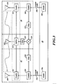
- FIGURE 3 is a high-level block diagram showing a two-element array antenna configuration in accordance with an alternate embodiment of the invention.
- An embodiment of the invention provides an approach that keeps the antenna components simple while nonetheless generating a reference source at the antenna for phase calibrating the cables.
- the antenna includes, for example, a frequency multiplier or mixer.
- the TCAS or system that requires phase calibration of the cables transmits a signal at a sub-multiple of the desired calibration frequency.
- the frequency multiplier at the antenna then generates the desired frequency.
- the multiplier is designed so that it would not function for regular operations of the TCAS or system, but would operate when the sub-multiple frequency signal was transmitted by the TCAS.
- the TCAS or system transmits two signals with frequencies such that the sum or difference of these signals produces the desired calibration frequency.
- the TRP system 49 is configured to transmit to antenna element 42 a first input signal, and to element 44 a second input signal, each at a sub-multiple of a desired first calibration frequency (e.g., 1030 MHz).
- a desired first calibration frequency e.g. 1030 MHz.
- These input signals may be respectively generated by LRUs 50a, 50b or by a single one of LRUs 50a, 50b.
- Input-side filters 220, 235 which may include low-pass filters, are configured to pass to the frequency multipliers 265, 270, respectively, only signals at frequencies in a finite range including the frequencies (e.g., 515 MHz) of the first and second input signals. In this manner, the illustrated embodiment ensures that the multipliers 265, 270 are idle or otherwise non-functional for regular operations of the antenna system, and will be operational only during calibration processes.
- Output-side filters 225, 240 which may include band-pass filters, are configured to pass to the TRP system 49 only signals at frequencies in a finite range including the frequency of the desired calibration signal (e.g., 1030 MHz).
- the desired calibration signals output by the filters 225, 240 are coupled back to the antenna cables 52a, 52b by coupling devices 245, 255. These coupled signals travel by the antenna cables 52a, 52b to the TRP system 49.
- the TRP system 49 measures the phase information associated with these signals.
- the above-described measurement process may be repeated using sub-multiples of a second frequency (e.g. , 1090 MHz) of a different desired calibration signal that is not harmonically related to the first frequency (e.g. , 1030 MHz).
- the TRP system 49 may use the phase information associated with the received calibration signals (e.g. , at 1030 MHz and 1090 MHz) to calculate the relative phase difference between antenna cables 52a, 52b.
- the mixer element 310 may be passive or active in operation.
- the mixer may be constructed from 1, 2, or 4 diodes or transistors which are interconnected with printed copper structures and/or wire wound balun transformers.
- the diodes/transistors may not require any type of DC bias voltage or current in order to operate. Rather, one of the two RF signals applied to the mixer is at a level sufficient to "drive" the diodes/transistors into conduction on at least one half cycle of the signal's sinewave. This provides the switching function that results in frequency mixing (addition and substraction). Since the mixer does not require any DC power, it is typically considered a passive circuit even though it contains semiconductor devices.
- the TRP system 49 is configured to transmit to antenna element 42 a first input signal at a first frequency, and to element 44 a second input signal at a second frequency, which may or may not be different from the first frequency.
- These input signals may be respectively generated by LRUs 50a, 50b or by a single one of LRUs 50a, 50b.
- Input-side filters 220, 235 which may include low-pass filters, are configured to pass to the mixer element 310 only signals at frequencies in a finite range including the first and second frequencies of the first and second input signals. In this manner, the illustrated embodiment ensures that the mixer element 310 is idle or otherwise non-functional for regular operations of the antenna system, and will be operational only during calibration processes. While the illustrated embodiment employs filtering devices, it should be recognized that selective attenuation may be alternatively accomplished by frequency-selective loading by short or open circuits, or other appropriate techniques.
- Output-side filter 225 which may include one or more band-pass filters, is configured to pass to the TRP system 49 only signals at frequencies in a finite range including the frequency of the desired calibration signal ( e.g. , 1030 or 1090 MHz).
- the desired calibration signal output by the filter 225 may be coupled back to the antenna cables 52a, 52b in one of at least two ways.
- splitter element 315 is configured to provide the first calibration signal to the cables 52a, 52b, by way of coupling devices 245, 255, for transmission to the TRP system 49.
- probe 305 is configured to wirelessly provide the first calibration signal to the cables 52a, 52b. In either case, this coupled first calibration signal travels by the antenna cables 52a, 52b to the TRP system 49.
- the TRP system 49 may use the phase information associated with the received calibration signal (e.g. , at 1030 MHz and 1090 MHz) to calculate the relative phase difference between antenna cables 52a, 52b.
- antenna elements 42, 44 are respectively coupled to the TRP system 49 by single coaxial cables 52a, 52b.
- the TRP system 49 may include one or more LRUs 50a, 50b coupled to cables 52a, 52b.
- the antenna elements 42, 44 may respectively include radiating structures 205, 210, attenuation elements, such as filters 220, 235, bias tees 450, 460 and signal-coupling elements 245, 255.
- Element 42 may further include an oscillator element 410, an attenuation element, such as filter 225, and either a splitter element 415 or a probe 405.
- the TRP system 49 is configured to transmit to antenna element 42, via cable 52a, a first activation signal at a first voltage or current. Transmission of the activation signal may be accomplished via a center conductor (not shown) of cable 52a.
- Input-side filter 220 which may include a low-pass filter, may be configured to pass to the oscillator element 410 only signals at low frequencies in a finite range including DC. In this manner, the illustrated embodiment ensures that the oscillator element 410 is idle or otherwise non-functional for regular operations of the antenna system, and will be operational only during calibration processes. While the illustrated embodiment employs filtering devices, it should be recognized that selective attenuation may be alternatively accomplished by frequency-selective loading by short or open circuits, or other appropriate techniques.
- the oscillator element 410 In response to the first activation signal, the oscillator element 410 provides a first calibration signal at a desired first calibration frequency (e.g ., 1030 MHz).
- a desired first calibration frequency e.g . 1030 MHz.
- the first desired calibration signal output by the filter 225 may be coupled back to the antenna cables 52a, 52b in one of at least two ways.
- splitter element 415 is configured to provide the first calibration signal to the cables 52a, 52b, by way of coupling devices 245, 255, for transmission to the TRP system 49.
- probe 405 is configured to wirelessly provide the first calibration signal to the cables 52a, 52b. In either case, this coupled first calibration signal travels by the antenna cables 52a, 52b to the TRP system 49.
- the TRP system 49 may use the phase information associated with the received first calibration signal (e.g. , 1030 MHz) to calculate the relative phase difference between antenna cables 52a, 52b.
- the TRP system 49 may transmit to antenna element 42, via cable 52a, a second activation signal at a second voltage or current.
- Input-side filter 220 which may include a low-pass filter, is configured to attenuate to the oscillator element 410 only signals at frequencies in a finite range including the second frequency of the second activation signal.
- the oscillator element 410 provides a second calibration signal at a desired calibration frequency (e.g. , 1090 MHz).
- L-band antennas integrated into skin surfaces of an aircraft could be used.
- a top two-element antenna and a bottom two-element antenna could be used with the first antenna being replaced by the first element of the top two-element antenna, the second antenna being replaced by the second element of the top two-element antenna, the third antenna being replaced by the first element of the bottom two-element antenna, and the fourth antenna being replaced by the second element of the bottom two-element antenna.
- the scope of the invention is not limited by the disclosure of the preferred embodiment.
Landscapes
- Engineering & Computer Science (AREA)
- Radar, Positioning & Navigation (AREA)
- Remote Sensing (AREA)
- Physics & Mathematics (AREA)
- General Physics & Mathematics (AREA)
- Aviation & Aerospace Engineering (AREA)
- Electromagnetism (AREA)
- Computer Networks & Wireless Communication (AREA)
- Variable-Direction Aerials And Aerial Arrays (AREA)
- Radio Transmission System (AREA)
Description
- Current Traffic Collision Avoidance System (TCAS) installations are expensive. Dual TCAS installations are even more so because they require an extensive amount of cable and/or coaxial cable switches.
U.S. Patent No. 4,855,748 describes a system and method for determining TCAS bearing estimation using a four-element planar array antenna. TCAS installations typically use two such four-element antennas, one on the top surface of an aircraft, and the other on the bottom surface of the aircraft. This typically requires a coaxial cable connection for each antenna element, resulting in at least eight total cables. This results in considerable weight and expense. -
U.S. Patent No. 7,583,223 discloses a system that includes a first antenna and a second antenna located on a top surface of an aircraft, spaced apart along a first axis, as well as a third antenna and a fourth antenna located on a bottom surface of the aircraft, spaced apart along a second axis orthogonal to the first axis. The system also includes a transmitting, receiving, and processing system coupled to the first, second, third, and fourth antennas, wherein the transmitting, receiving, and processing system is configured to transmit TCAS interrogations, receive TCAS replies, and process the TCAS replies to determine the relative bearing of a second aircraft from the first aircraft. Such a system provides a TCAS antenna system, employing two pairs of two-element arrays, that uses less cabling than previous attempts, specifically, four cables (two to top and two to bottom) instead of eight cables (four to top and four to bottom). -
U.S. Patent No. 4,855,748 discloses an approach by which cables associated with four-element antenna arrays may be phase calibrated. However, such approach cannot be employed for phase calibration of the above-described two-element arrays.US 6392598 discloses an apparatus and method for determining angle-of-arrival of a received radiofrequency signal.US 3091765 discloses an anti-collision system for ships and planes.US 4673944 discloses a direction-finding interferometer including an anti-calibration subsystem using bi-directional transmissions at a common frequency.US 5008844 discloses a transmit system for collision avoidance systems having auto calibration. - The present invention in its various aspects is as set out in the appended claims. In an embodiment, a two-element array antenna system includes a first antenna element and a second antenna element. The first and second antenna elements respectively include first and second frequency multipliers. A transmitting, receiving, and processing (TRP) system is coupled to the first and second antenna elements via, respectively, a single first transmission element and a single second transmission element. The TRP system is configured to transmit to the first antenna element a first input signal at a sub-multiple of a first frequency, receive from the first frequency multiplier a first calibration signal based on the first input signal, transmit to the second antenna element a second input signal at a sub-multiple of the first frequency, receive from the second frequency multiplier a second calibration signal based on the second input signal, and determine, based on the calibration signals, a relative phase difference between the first and second transmission elements.
- Preferred and alternative embodiments of the present invention are described in detail below with reference to the following drawings:
-
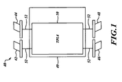
FIGURE 1 is a high-level block diagram showing an antenna configuration for a TCAS system in accordance with an embodiment of the invention; -
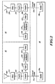
FIGURE 2 is a high-level block diagram showing a two-element array antenna configuration in accordance with an embodiment of the invention; -
FIGURE 3 is a high-level block diagram showing a two-element array antenna configuration in accordance with an alternate embodiment of the invention; and -
FIGURE 4 is a high-level block diagram showing a two-element array antenna configuration in accordance with a second alternate embodiment of the invention. - An embodiment of the invention provides an approach that keeps the antenna components simple while nonetheless generating a reference source at the antenna for phase calibrating the cables. The antenna includes, for example, a frequency multiplier or mixer. The TCAS or system that requires phase calibration of the cables transmits a signal at a sub-multiple of the desired calibration frequency. The frequency multiplier at the antenna then generates the desired frequency. The multiplier is designed so that it would not function for regular operations of the TCAS or system, but would operate when the sub-multiple frequency signal was transmitted by the TCAS. Alternatively, the TCAS or system transmits two signals with frequencies such that the sum or difference of these signals produces the desired calibration frequency.
-
FIGURE 1 is a high-level block diagram showing a TCAS system 40 within which an embodiment of the invention may be implemented. The system 40 includes afirst top antenna 42, asecond top antenna 44, afirst bottom antenna 46, and asecond bottom antenna 48. Each of theantennas system 49 by a transmission element, such as acable 52, resulting in fourtotal cables 52 for the system 40. Thesystem 49 includes a Line Replaceable Unit (LRU) 50, designated as TPL4 that includes transmitting, receiving, and processing components. - When installed on an aircraft, the
first top antenna 42 and thesecond top antenna 44 are positioned on a top surface of the aircraft, spaced apart along a first axis while thefirst bottom antenna 46 and thesecond bottom antenna 48 are positioned on a bottom surface of the aircraft, spaced apart along a second axis orthogonal to the first axis. In an example embodiment, theantennas - Referring now to
FIGURE 2 , illustrated is a phase calibration approach for a two-element array according to an embodiment of the invention. It should be understood that the following discussion of phase-calibration techniques employed by varying embodiments of the invention applies to antenna arrays including no more or fewer than two antenna elements. In the illustrated embodiment,antenna elements TRP system 49 by single coaxial cables 52a, 52b. As illustrated, theTRP system 49 may include one ormore LRUs antenna elements radiating structures filters coupling elements frequency multipliers - In operation, when phase calibration of cables 52a, 52b is desired, the
TRP system 49 is configured to transmit to antenna element 42 a first input signal, and to element 44 a second input signal, each at a sub-multiple of a desired first calibration frequency (e.g., 1030 MHz). These input signals may be respectively generated byLRUs LRUs - Input-
side filters frequency multipliers multipliers - The
frequency multipliers multipliers multipliers filters - Output-
side filters TRP system 49 only signals at frequencies in a finite range including the frequency of the desired calibration signal (e.g., 1030 MHz). - The desired calibration signals output by the
filters coupling devices TRP system 49. TheTRP system 49 measures the phase information associated with these signals. - The above-described measurement process may be repeated using sub-multiples of a second frequency (e.g., 1090 MHz) of a different desired calibration signal that is not harmonically related to the first frequency (e.g., 1030 MHz). The
TRP system 49 may use the phase information associated with the received calibration signals (e.g., at 1030 MHz and 1090 MHz) to calculate the relative phase difference between antenna cables 52a, 52b. - Referring now to
FIGURE 3 , illustrated is a phase calibration approach for a two-element array according to an alternative embodiment of the invention. In the illustrated embodiment,antenna elements TRP system 49 by single coaxial cables 52a, 52b. As illustrated, theTRP system 49 may include one ormore LRUs antenna elements radiating structures filters coupling elements elements mixer element 310, an attenuation element, such asfilter 225, and either asplitter element 315 or aprobe 305. Alternatively, themixer element 310,filter 225,splitter element 315 and/orprobe 305 may be external, but coupled, toelements - The
mixer element 310 may be passive or active in operation. The mixer may be constructed from 1, 2, or 4 diodes or transistors which are interconnected with printed copper structures and/or wire wound balun transformers. The diodes/transistors may not require any type of DC bias voltage or current in order to operate. Rather, one of the two RF signals applied to the mixer is at a level sufficient to "drive" the diodes/transistors into conduction on at least one half cycle of the signal's sinewave. This provides the switching function that results in frequency mixing (addition and substraction). Since the mixer does not require any DC power, it is typically considered a passive circuit even though it contains semiconductor devices. - In operation, when phase calibration of cables 52a, 52b is desired, the
TRP system 49 is configured to transmit to antenna element 42 a first input signal at a first frequency, and to element 44 a second input signal at a second frequency, which may or may not be different from the first frequency. These input signals may be respectively generated byLRUs LRUs - Input-
side filters mixer element 310 only signals at frequencies in a finite range including the first and second frequencies of the first and second input signals. In this manner, the illustrated embodiment ensures that themixer element 310 is idle or otherwise non-functional for regular operations of the antenna system, and will be operational only during calibration processes. While the illustrated embodiment employs filtering devices, it should be recognized that selective attenuation may be alternatively accomplished by frequency-selective loading by short or open circuits, or other appropriate techniques. - The frequencies of the first and second input signals generated by the
TRP system 49 are such that the sum or difference, as generated by the mixer, of these signals provides a first calibration signal at a desired calibration frequency (e.g., 1030 or 1090 MHz). - Output-
side filter 225, which may include one or more band-pass filters, is configured to pass to theTRP system 49 only signals at frequencies in a finite range including the frequency of the desired calibration signal (e.g., 1030 or 1090 MHz). - The desired calibration signal output by the
filter 225 may be coupled back to the antenna cables 52a, 52b in one of at least two ways. In an embodiment,splitter element 315 is configured to provide the first calibration signal to the cables 52a, 52b, by way ofcoupling devices TRP system 49. Alternatively,probe 305 is configured to wirelessly provide the first calibration signal to the cables 52a, 52b. In either case, this coupled first calibration signal travels by the antenna cables 52a, 52b to theTRP system 49. TheTRP system 49 may use the phase information associated with the received calibration signal (e.g., at 1030 MHz and 1090 MHz) to calculate the relative phase difference between antenna cables 52a, 52b. - Referring now to
FIGURE 4 , illustrated is a phase calibration approach for a two-element array according to a second alternative embodiment of the invention. In the illustrated embodiment,antenna elements TRP system 49 by single coaxial cables 52a, 52b. As illustrated, theTRP system 49 may include one or more LRUs 50a, 50b coupled to cables 52a, 52b. Theantenna elements structures filters bias tees coupling elements Element 42 may further include anoscillator element 410, an attenuation element, such asfilter 225, and either asplitter element 415 or aprobe 405. - In operation, when phase calibration of cables 52a, 52b is desired, the
TRP system 49 is configured to transmit toantenna element 42, via cable 52a, a first activation signal at a first voltage or current. Transmission of the activation signal may be accomplished via a center conductor (not shown) of cable 52a. - Input-
side filter 220, which may include a low-pass filter, may be configured to pass to theoscillator element 410 only signals at low frequencies in a finite range including DC. In this manner, the illustrated embodiment ensures that theoscillator element 410 is idle or otherwise non-functional for regular operations of the antenna system, and will be operational only during calibration processes. While the illustrated embodiment employs filtering devices, it should be recognized that selective attenuation may be alternatively accomplished by frequency-selective loading by short or open circuits, or other appropriate techniques. - In response to the first activation signal, the
oscillator element 410 provides a first calibration signal at a desired first calibration frequency (e.g., 1030 MHz). - Output-
side filter 225, which may include one or more band-pass filters, is configured to pass to theTRP system 49 only signals at frequencies in a finite range including the frequency of the desired calibration signal (e.g., 1030 MHz). - The first desired calibration signal output by the
filter 225 may be coupled back to the antenna cables 52a, 52b in one of at least two ways. In an embodiment,splitter element 415 is configured to provide the first calibration signal to the cables 52a, 52b, by way ofcoupling devices TRP system 49. Alternatively,probe 405 is configured to wirelessly provide the first calibration signal to the cables 52a, 52b. In either case, this coupled first calibration signal travels by the antenna cables 52a, 52b to theTRP system 49. TheTRP system 49 may use the phase information associated with the received first calibration signal (e.g., 1030 MHz) to calculate the relative phase difference between antenna cables 52a, 52b. - Subsequently, and in a fashion similar to that described above, the
TRP system 49 may transmit toantenna element 42, via cable 52a, a second activation signal at a second voltage or current. - Input-
side filter 220, which may include a low-pass filter, is configured to attenuate to theoscillator element 410 only signals at frequencies in a finite range including the second frequency of the second activation signal. In response to the second activation signal, theoscillator element 410 provides a second calibration signal at a desired calibration frequency (e.g., 1090 MHz). - Output-
side filter 225, which may include one or more band-pass filters, is configured to pass to theTRP system 49 only signals at frequencies in a finite range including the frequency of the second desired calibration signal (e.g., 1090 MHz). - The second desired calibration signal output by the
filter 225 may be coupled back to the antenna cables 52a, 52b in a manner described above. TheTRP system 49 may use the phase information associated with the received first and second calibration signals (e.g., at 1030 MHz and 1090 MHz) to calculate the relative phase difference between antenna cables 52a, 52b. - In an embodiment, and as illustrated by dashed elements in
FIGURE 4 ,element 44 may include asecond oscillator element 420. In such an embodiment, subsequent to theTRP system 49 transmitting toantenna element 42, via cable 52a, the first activation signal at a first voltage or current, theTRP system 49 may transmit toantenna element 44, via cable 52b, a second activation signal at a second voltage or current. In a manner similar to that described above, thesecond oscillator element 420, in response to the second activation signal, provides, viafilter 225 and one ofsplitter 415 or probe 405, a second calibration signal at a desired calibration frequency (e.g., 1090 MHz), such that theTRP system 49 may similarly use the phase information associated with the received first and second calibration signals (e.g., at 1030 MHz and 1090 MHz) to calculate the relative phase difference between antenna cables 52a, 52b. - While the preferred embodiment of the invention has been illustrated and described as noted above, rather than using L-band blade antennas, L-band antennas integrated into skin surfaces of an aircraft could be used. Additionally, a top two-element antenna and a bottom two-element antenna could be used with the first antenna being replaced by the first element of the top two-element antenna, the second antenna being replaced by the second element of the top two-element antenna, the third antenna being replaced by the first element of the bottom two-element antenna, and the fourth antenna being replaced by the second element of the bottom two-element antenna. The scope of the invention is not limited by the disclosure of the preferred embodiment.
Claims (6)
- A two-element array antenna system, comprising:a first antenna element (42) and a second antenna element (44), the first antenna element comprising a first frequency multiplier (265), the second antenna element comprising a second frequency multiplier (270); anda transmitting, receiving, and processing (TRP) system (49) coupled to the first and second antenna elements, the TRP system being coupled to the first antenna element via a single first transmission element (52a), the TRP system being coupled to the second antenna element via a single second transmission element (52b),wherein the TRP system is configured to:transmit to the first antenna element a first input signal at a sub-multiple of a first frequency,receive from the first frequency multiplier, a first calibration signal based on the first input signal,transmit to the second antenna element a second input signal at a sub-multiple of the first frequency,receive from the second frequency multiplier a second calibration signal based on the second input signal, anddetermine, based on the first and second calibration signals, a relative phase difference between the first and second transmission elements.
- The system of claim 1, wherein the TRP system (49) is further configured to:transmit to the first antenna element (42) a third input signal at a sub-multiple of a second frequency different from the first frequency,receive from the first frequency multiplier (265) a third calibration signal based on the third input signal,transmit to the second antenna element (44) a fourth input signal at a sub-multiple of the second frequency,receive from the second frequency multiplier (270) a fourth calibration signal based on the fourth input signal, anddetermine, based on the first, second, third and fourth calibration signals, a relative phase difference between the first and second transmission elements (52a, 52b).
- The system of claim 2, wherein:the first antenna element (42) further comprises a first input-side attenuation element (220); andthe second antenna element (44) further comprises a second input-side attenuation element (235),wherein the first and second input-side attenuation elements are configured to attenuate to the first and second frequency multipliers (265, 270) only signals at frequencies in a finite range including the frequencies of the first, second, third and fourth input signals.
- The system of claim 2, wherein:the first antenna element (42) further comprises a first output-side attenuation element (225); andthe second antenna element (44) further comprises a second output-side attenuation element (240),wherein the first and second output-side attenuation elements are configured to attenuate to the TRP system (49) only signals at frequencies in a finite range including the first and second frequencies.
- The system of claim 3, wherein the first and second input-side attenuation elements (220, 235) comprise low-pass filters.
- The system of claim 1, wherein the TRP system (49) includes a first transmitter (50a) coupled to the first transmission element (52a) and configured to generate the first input signal, and a second transmitter (50b) coupled to the second transmission element (52b) and configured to generate the second input signal.
Applications Claiming Priority (2)
| Application Number | Priority Date | Filing Date | Title |
|---|---|---|---|
| US16850009P | 2009-04-10 | 2009-04-10 | |
| US12/756,311 US8242951B2 (en) | 2009-04-10 | 2010-04-08 | System and method for generating a reference signal for phase calibration of a system |
Publications (3)
| Publication Number | Publication Date |
|---|---|
| EP2239596A2 EP2239596A2 (en) | 2010-10-13 |
| EP2239596A3 EP2239596A3 (en) | 2011-11-09 |
| EP2239596B1 true EP2239596B1 (en) | 2013-09-11 |
Family
ID=42244147
Family Applications (1)
| Application Number | Title | Priority Date | Filing Date |
|---|---|---|---|
| EP10159568.4A Active EP2239596B1 (en) | 2009-04-10 | 2010-04-09 | System and method for generating a reference signal for phase calibration of a system |
Country Status (3)
| Country | Link |
|---|---|
| US (1) | US8242951B2 (en) |
| EP (1) | EP2239596B1 (en) |
| CN (1) | CN101867096B (en) |
Families Citing this family (6)
| Publication number | Priority date | Publication date | Assignee | Title |
|---|---|---|---|---|
| US8242951B2 (en) * | 2009-04-10 | 2012-08-14 | Honeywell International Inc. | System and method for generating a reference signal for phase calibration of a system |
| CN104215948B (en) * | 2014-08-22 | 2017-05-10 | 西安空间无线电技术研究所 | Spaceborne SAR echo correction and pulse compression method based on reference signals |
| DE102018208992A1 (en) * | 2018-06-07 | 2019-12-12 | Robert Bosch Gmbh | Radar Sensor System |
| TWI678846B (en) * | 2018-11-15 | 2019-12-01 | 財團法人工業技術研究院 | Antenna device and method for calibrating antenna device |
| US11152990B1 (en) | 2020-04-16 | 2021-10-19 | Honeywell International Inc. | Simplified TCAS surveillance |
| CN111832115B (en) * | 2020-06-02 | 2023-12-19 | 哈尔滨工业大学(深圳)(哈尔滨工业大学深圳科技创新研究院) | Integrated frequency design method for symmetric late-lead correction |
Family Cites Families (20)
| Publication number | Priority date | Publication date | Assignee | Title |
|---|---|---|---|---|
| US3091765A (en) | 1957-06-13 | 1963-05-28 | Jules H Sreb | Anti-collision system for ships and planes |
| US4673944A (en) | 1984-03-12 | 1987-06-16 | Hughes Aircraft Company | Autocalibrating interferometer |
| DE3866940D1 (en) * | 1987-05-02 | 1992-01-30 | Kubota Ltd | INTERNAL COMBUSTION ENGINE WITH SIMULTANEOUS USE OF LIQUID COOLING AND FAN VENTILATION. |
| US4855749A (en) | 1988-02-26 | 1989-08-08 | The United States Of America As Represented By The Secretary Of The Air Force | Opto-electronic vivaldi transceiver |
| US4855748A (en) | 1988-03-18 | 1989-08-08 | Allied-Signal Inc. | TCAS bearing estimation receiver using a 4 element antenna |
| US5008844A (en) | 1990-01-10 | 1991-04-16 | Allied-Signal Inc. | Collision avoidance transmit system with autocalibration |
| US5493710A (en) * | 1991-08-02 | 1996-02-20 | Hitachi, Ltd. | Communication system having oscillation frequency calibrating function |
| US5469172A (en) * | 1993-11-16 | 1995-11-21 | Bf Goodrich Flightsystem, Inc. | Calibration method and apparatus for receiving transponder reply signals |
| US5572219A (en) * | 1995-07-07 | 1996-11-05 | General Electric Company | Method and apparatus for remotely calibrating a phased array system used for satellite communication |
| US6262679B1 (en) * | 1999-04-08 | 2001-07-17 | Honeywell International Inc. | Midair collision avoidance system |
| US6285313B1 (en) | 1999-09-21 | 2001-09-04 | Rockwell Collins | TCAS transmitter phase tuning system and method |
| US6597730B1 (en) * | 1999-11-03 | 2003-07-22 | Northrop Grumman Corporation | Satellite communication array transceiver |
| WO2001057546A1 (en) | 2000-02-01 | 2001-08-09 | Honeywell International Inc. | Cable phase calibration in a tcas |
| US20030030582A1 (en) * | 2001-08-10 | 2003-02-13 | Vickers Roger S. | Environment measurement methods, systems, media, signals and data structures |
| US7482976B2 (en) * | 2006-04-10 | 2009-01-27 | Aviation Communication & Surveillance Systems | Antenna calibration method and apparatus |
| US7576686B2 (en) * | 2006-08-07 | 2009-08-18 | Garmin International, Inc. | Method and system for calibrating an antenna array for an aircraft surveillance system |
| US7583223B2 (en) | 2006-09-18 | 2009-09-01 | Honeywell International Inc. | Distributed and Cable reduced TCAS |
| US8049662B2 (en) | 2007-07-23 | 2011-11-01 | Aviation Communication&Surveillance Systems LLC | Systems and methods for antenna calibration |
| US8242951B2 (en) * | 2009-04-10 | 2012-08-14 | Honeywell International Inc. | System and method for generating a reference signal for phase calibration of a system |
| US8897717B2 (en) * | 2010-07-28 | 2014-11-25 | Honeywell International Inc. | Dual-feed antenna array with integral comparison circuit for phase and amplitude calibration |
-
2010
- 2010-04-08 US US12/756,311 patent/US8242951B2/en active Active
- 2010-04-09 EP EP10159568.4A patent/EP2239596B1/en active Active
- 2010-04-09 CN CN201010188000.0A patent/CN101867096B/en not_active Expired - Fee Related
Also Published As
| Publication number | Publication date |
|---|---|
| EP2239596A3 (en) | 2011-11-09 |
| US20100259439A1 (en) | 2010-10-14 |
| CN101867096A (en) | 2010-10-20 |
| EP2239596A2 (en) | 2010-10-13 |
| CN101867096B (en) | 2014-08-06 |
| US8242951B2 (en) | 2012-08-14 |
Similar Documents
| Publication | Publication Date | Title |
|---|---|---|
| US7583223B2 (en) | Distributed and Cable reduced TCAS | |
| US8897717B2 (en) | Dual-feed antenna array with integral comparison circuit for phase and amplitude calibration | |
| US8242951B2 (en) | System and method for generating a reference signal for phase calibration of a system | |
| KR101060389B1 (en) | Multiple Separation Method and Apparatus for Near Field Measurement Radar | |
| US11125797B2 (en) | Signal generator and a measurement system including signal generator | |
| US12153125B2 (en) | Radar system and method for performing direction of arrival estimation in a radar system | |
| CN110297217A (en) | Radar system with multiple radar chips | |
| EP3339899A1 (en) | Cascaded transceiver integrated circuit | |
| US10469183B1 (en) | Antenna device and method for calibrating antenna device | |
| US11480667B2 (en) | Systems and methods for providing an integrated TCAS, transponder, and DME system using a dedicated DME antenna | |
| US20090033541A1 (en) | Dme ground apparatus | |
| CN118671765A (en) | Cascade radar system with reflection mitigation from transmitting vehicle | |
| EP3681044B1 (en) | Fixed low intermediate frequency approach to distance measurement transmitter | |
| US12078750B2 (en) | Receiver, radar apparatus including receiver, vehicle including receiver, and communication system including receiver | |
| US4970510A (en) | Self test avionics equipment | |
| US20180033319A1 (en) | Systems and methods for providing an integrated tcas and dme system using an omnidirectional antenna | |
| US11360208B2 (en) | Sensor system for a vehicle and method for operating a sensor system for a vehicle | |
| Liu et al. | A versatile digital antenna array transceiving system with online self-calibration | |
| Jaromi et al. | Structure and software elements of ENAVI radar for large drones | |
| CN113050044B (en) | Radar systems and electronics | |
| RU2691129C1 (en) | All-round radar | |
| CN103222186B (en) | Method and device for processing signals | |
| KR102534141B1 (en) | Complex permittivity estimating apparatus and method | |
| US9354306B1 (en) | Single antenna altimeter system and related method | |
| CN101923156A (en) | Pulse detecting equipment |
Legal Events
| Date | Code | Title | Description |
|---|---|---|---|
| PUAI | Public reference made under article 153(3) epc to a published international application that has entered the european phase |
Free format text: ORIGINAL CODE: 0009012 |
|
| 17P | Request for examination filed |
Effective date: 20100409 |
|
| AK | Designated contracting states |
Kind code of ref document: A2 Designated state(s): AT BE BG CH CY CZ DE DK EE ES FI FR GB GR HR HU IE IS IT LI LT LU LV MC MK MT NL NO PL PT RO SE SI SK SM TR |
|
| AX | Request for extension of the european patent |
Extension state: AL BA ME RS |
|
| PUAL | Search report despatched |
Free format text: ORIGINAL CODE: 0009013 |
|
| AK | Designated contracting states |
Kind code of ref document: A3 Designated state(s): AT BE BG CH CY CZ DE DK EE ES FI FR GB GR HR HU IE IS IT LI LT LU LV MC MK MT NL NO PL PT RO SE SI SK SM TR |
|
| AX | Request for extension of the european patent |
Extension state: AL BA ME RS |
|
| RIC1 | Information provided on ipc code assigned before grant |
Ipc: G01S 7/48 20060101AFI20111005BHEP Ipc: G01S 17/02 20060101ALI20111005BHEP |
|
| 17Q | First examination report despatched |
Effective date: 20111024 |
|
| REG | Reference to a national code |
Ref country code: DE Ref legal event code: R079 Ref document number: 602010010145 Country of ref document: DE Free format text: PREVIOUS MAIN CLASS: G01S0007480000 Ipc: G01S0013930000 |
|
| RIC1 | Information provided on ipc code assigned before grant |
Ipc: G01S 3/02 20060101ALI20130319BHEP Ipc: G01S 13/93 20060101AFI20130319BHEP |
|
| GRAP | Despatch of communication of intention to grant a patent |
Free format text: ORIGINAL CODE: EPIDOSNIGR1 |
|
| INTG | Intention to grant announced |
Effective date: 20130426 |
|
| GRAS | Grant fee paid |
Free format text: ORIGINAL CODE: EPIDOSNIGR3 |
|
| GRAA | (expected) grant |
Free format text: ORIGINAL CODE: 0009210 |
|
| AK | Designated contracting states |
Kind code of ref document: B1 Designated state(s): AT BE BG CH CY CZ DE DK EE ES FI FR GB GR HR HU IE IS IT LI LT LU LV MC MK MT NL NO PL PT RO SE SI SK SM TR |
|
| REG | Reference to a national code |
Ref country code: GB Ref legal event code: FG4D |
|
| REG | Reference to a national code |
Ref country code: CH Ref legal event code: EP |
|
| REG | Reference to a national code |
Ref country code: AT Ref legal event code: REF Ref document number: 631937 Country of ref document: AT Kind code of ref document: T Effective date: 20130915 |
|
| REG | Reference to a national code |
Ref country code: IE Ref legal event code: FG4D |
|
| REG | Reference to a national code |
Ref country code: DE Ref legal event code: R096 Ref document number: 602010010145 Country of ref document: DE Effective date: 20131107 |
|
| PG25 | Lapsed in a contracting state [announced via postgrant information from national office to epo] |
Ref country code: SE Free format text: LAPSE BECAUSE OF FAILURE TO SUBMIT A TRANSLATION OF THE DESCRIPTION OR TO PAY THE FEE WITHIN THE PRESCRIBED TIME-LIMIT Effective date: 20130911 Ref country code: CY Free format text: LAPSE BECAUSE OF FAILURE TO SUBMIT A TRANSLATION OF THE DESCRIPTION OR TO PAY THE FEE WITHIN THE PRESCRIBED TIME-LIMIT Effective date: 20130911 Ref country code: LT Free format text: LAPSE BECAUSE OF FAILURE TO SUBMIT A TRANSLATION OF THE DESCRIPTION OR TO PAY THE FEE WITHIN THE PRESCRIBED TIME-LIMIT Effective date: 20130911 Ref country code: HR Free format text: LAPSE BECAUSE OF FAILURE TO SUBMIT A TRANSLATION OF THE DESCRIPTION OR TO PAY THE FEE WITHIN THE PRESCRIBED TIME-LIMIT Effective date: 20130911 Ref country code: NO Free format text: LAPSE BECAUSE OF FAILURE TO SUBMIT A TRANSLATION OF THE DESCRIPTION OR TO PAY THE FEE WITHIN THE PRESCRIBED TIME-LIMIT Effective date: 20131211 |
|
| REG | Reference to a national code |
Ref country code: NL Ref legal event code: VDEP Effective date: 20130911 |
|
| REG | Reference to a national code |
Ref country code: AT Ref legal event code: MK05 Ref document number: 631937 Country of ref document: AT Kind code of ref document: T Effective date: 20130911 |
|
| REG | Reference to a national code |
Ref country code: LT Ref legal event code: MG4D |
|
| PG25 | Lapsed in a contracting state [announced via postgrant information from national office to epo] |
Ref country code: FI Free format text: LAPSE BECAUSE OF FAILURE TO SUBMIT A TRANSLATION OF THE DESCRIPTION OR TO PAY THE FEE WITHIN THE PRESCRIBED TIME-LIMIT Effective date: 20130911 Ref country code: GR Free format text: LAPSE BECAUSE OF FAILURE TO SUBMIT A TRANSLATION OF THE DESCRIPTION OR TO PAY THE FEE WITHIN THE PRESCRIBED TIME-LIMIT Effective date: 20131212 Ref country code: ES Free format text: LAPSE BECAUSE OF FAILURE TO SUBMIT A TRANSLATION OF THE DESCRIPTION OR TO PAY THE FEE WITHIN THE PRESCRIBED TIME-LIMIT Effective date: 20130911 Ref country code: LV Free format text: LAPSE BECAUSE OF FAILURE TO SUBMIT A TRANSLATION OF THE DESCRIPTION OR TO PAY THE FEE WITHIN THE PRESCRIBED TIME-LIMIT Effective date: 20130911 Ref country code: SI Free format text: LAPSE BECAUSE OF FAILURE TO SUBMIT A TRANSLATION OF THE DESCRIPTION OR TO PAY THE FEE WITHIN THE PRESCRIBED TIME-LIMIT Effective date: 20130911 |
|
| PG25 | Lapsed in a contracting state [announced via postgrant information from national office to epo] |
Ref country code: BE Free format text: LAPSE BECAUSE OF FAILURE TO SUBMIT A TRANSLATION OF THE DESCRIPTION OR TO PAY THE FEE WITHIN THE PRESCRIBED TIME-LIMIT Effective date: 20130911 |
|
| PG25 | Lapsed in a contracting state [announced via postgrant information from national office to epo] |
Ref country code: RO Free format text: LAPSE BECAUSE OF FAILURE TO SUBMIT A TRANSLATION OF THE DESCRIPTION OR TO PAY THE FEE WITHIN THE PRESCRIBED TIME-LIMIT Effective date: 20130911 Ref country code: EE Free format text: LAPSE BECAUSE OF FAILURE TO SUBMIT A TRANSLATION OF THE DESCRIPTION OR TO PAY THE FEE WITHIN THE PRESCRIBED TIME-LIMIT Effective date: 20130911 Ref country code: SK Free format text: LAPSE BECAUSE OF FAILURE TO SUBMIT A TRANSLATION OF THE DESCRIPTION OR TO PAY THE FEE WITHIN THE PRESCRIBED TIME-LIMIT Effective date: 20130911 Ref country code: IS Free format text: LAPSE BECAUSE OF FAILURE TO SUBMIT A TRANSLATION OF THE DESCRIPTION OR TO PAY THE FEE WITHIN THE PRESCRIBED TIME-LIMIT Effective date: 20140111 Ref country code: CZ Free format text: LAPSE BECAUSE OF FAILURE TO SUBMIT A TRANSLATION OF THE DESCRIPTION OR TO PAY THE FEE WITHIN THE PRESCRIBED TIME-LIMIT Effective date: 20130911 Ref country code: NL Free format text: LAPSE BECAUSE OF FAILURE TO SUBMIT A TRANSLATION OF THE DESCRIPTION OR TO PAY THE FEE WITHIN THE PRESCRIBED TIME-LIMIT Effective date: 20130911 |
|
| PG25 | Lapsed in a contracting state [announced via postgrant information from national office to epo] |
Ref country code: PL Free format text: LAPSE BECAUSE OF FAILURE TO SUBMIT A TRANSLATION OF THE DESCRIPTION OR TO PAY THE FEE WITHIN THE PRESCRIBED TIME-LIMIT Effective date: 20130911 Ref country code: AT Free format text: LAPSE BECAUSE OF FAILURE TO SUBMIT A TRANSLATION OF THE DESCRIPTION OR TO PAY THE FEE WITHIN THE PRESCRIBED TIME-LIMIT Effective date: 20130911 |
|
| REG | Reference to a national code |
Ref country code: DE Ref legal event code: R097 Ref document number: 602010010145 Country of ref document: DE |
|
| PG25 | Lapsed in a contracting state [announced via postgrant information from national office to epo] |
Ref country code: PT Free format text: LAPSE BECAUSE OF FAILURE TO SUBMIT A TRANSLATION OF THE DESCRIPTION OR TO PAY THE FEE WITHIN THE PRESCRIBED TIME-LIMIT Effective date: 20140113 |
|
| PLBE | No opposition filed within time limit |
Free format text: ORIGINAL CODE: 0009261 |
|
| STAA | Information on the status of an ep patent application or granted ep patent |
Free format text: STATUS: NO OPPOSITION FILED WITHIN TIME LIMIT |
|
| 26N | No opposition filed |
Effective date: 20140612 |
|
| PG25 | Lapsed in a contracting state [announced via postgrant information from national office to epo] |
Ref country code: IT Free format text: LAPSE BECAUSE OF FAILURE TO SUBMIT A TRANSLATION OF THE DESCRIPTION OR TO PAY THE FEE WITHIN THE PRESCRIBED TIME-LIMIT Effective date: 20130911 |
|
| REG | Reference to a national code |
Ref country code: DE Ref legal event code: R097 Ref document number: 602010010145 Country of ref document: DE Effective date: 20140612 |
|
| PG25 | Lapsed in a contracting state [announced via postgrant information from national office to epo] |
Ref country code: DK Free format text: LAPSE BECAUSE OF FAILURE TO SUBMIT A TRANSLATION OF THE DESCRIPTION OR TO PAY THE FEE WITHIN THE PRESCRIBED TIME-LIMIT Effective date: 20130911 |
|
| PG25 | Lapsed in a contracting state [announced via postgrant information from national office to epo] |
Ref country code: MC Free format text: LAPSE BECAUSE OF FAILURE TO SUBMIT A TRANSLATION OF THE DESCRIPTION OR TO PAY THE FEE WITHIN THE PRESCRIBED TIME-LIMIT Effective date: 20130911 Ref country code: LU Free format text: LAPSE BECAUSE OF FAILURE TO SUBMIT A TRANSLATION OF THE DESCRIPTION OR TO PAY THE FEE WITHIN THE PRESCRIBED TIME-LIMIT Effective date: 20140409 |
|
| REG | Reference to a national code |
Ref country code: CH Ref legal event code: PL |
|
| REG | Reference to a national code |
Ref country code: IE Ref legal event code: MM4A |
|
| PG25 | Lapsed in a contracting state [announced via postgrant information from national office to epo] |
Ref country code: CH Free format text: LAPSE BECAUSE OF NON-PAYMENT OF DUE FEES Effective date: 20140430 Ref country code: LI Free format text: LAPSE BECAUSE OF NON-PAYMENT OF DUE FEES Effective date: 20140430 |
|
| PG25 | Lapsed in a contracting state [announced via postgrant information from national office to epo] |
Ref country code: IE Free format text: LAPSE BECAUSE OF NON-PAYMENT OF DUE FEES Effective date: 20140409 |
|
| PGFP | Annual fee paid to national office [announced via postgrant information from national office to epo] |
Ref country code: GB Payment date: 20150325 Year of fee payment: 6 |
|
| PGFP | Annual fee paid to national office [announced via postgrant information from national office to epo] |
Ref country code: DE Payment date: 20150429 Year of fee payment: 6 |
|
| PG25 | Lapsed in a contracting state [announced via postgrant information from national office to epo] |
Ref country code: MT Free format text: LAPSE BECAUSE OF FAILURE TO SUBMIT A TRANSLATION OF THE DESCRIPTION OR TO PAY THE FEE WITHIN THE PRESCRIBED TIME-LIMIT Effective date: 20130911 |
|
| REG | Reference to a national code |
Ref country code: FR Ref legal event code: PLFP Year of fee payment: 7 |
|
| PG25 | Lapsed in a contracting state [announced via postgrant information from national office to epo] |
Ref country code: SM Free format text: LAPSE BECAUSE OF FAILURE TO SUBMIT A TRANSLATION OF THE DESCRIPTION OR TO PAY THE FEE WITHIN THE PRESCRIBED TIME-LIMIT Effective date: 20130911 |
|
| PG25 | Lapsed in a contracting state [announced via postgrant information from national office to epo] |
Ref country code: BG Free format text: LAPSE BECAUSE OF FAILURE TO SUBMIT A TRANSLATION OF THE DESCRIPTION OR TO PAY THE FEE WITHIN THE PRESCRIBED TIME-LIMIT Effective date: 20130911 |
|
| PG25 | Lapsed in a contracting state [announced via postgrant information from national office to epo] |
Ref country code: TR Free format text: LAPSE BECAUSE OF FAILURE TO SUBMIT A TRANSLATION OF THE DESCRIPTION OR TO PAY THE FEE WITHIN THE PRESCRIBED TIME-LIMIT Effective date: 20130911 Ref country code: HU Free format text: LAPSE BECAUSE OF FAILURE TO SUBMIT A TRANSLATION OF THE DESCRIPTION OR TO PAY THE FEE WITHIN THE PRESCRIBED TIME-LIMIT; INVALID AB INITIO Effective date: 20100409 |
|
| REG | Reference to a national code |
Ref country code: DE Ref legal event code: R119 Ref document number: 602010010145 Country of ref document: DE |
|
| GBPC | Gb: european patent ceased through non-payment of renewal fee |
Effective date: 20160409 |
|
| PG25 | Lapsed in a contracting state [announced via postgrant information from national office to epo] |
Ref country code: GB Free format text: LAPSE BECAUSE OF NON-PAYMENT OF DUE FEES Effective date: 20160409 Ref country code: DE Free format text: LAPSE BECAUSE OF NON-PAYMENT OF DUE FEES Effective date: 20161101 |
|
| REG | Reference to a national code |
Ref country code: FR Ref legal event code: PLFP Year of fee payment: 8 |
|
| REG | Reference to a national code |
Ref country code: FR Ref legal event code: PLFP Year of fee payment: 9 |
|
| PG25 | Lapsed in a contracting state [announced via postgrant information from national office to epo] |
Ref country code: MK Free format text: LAPSE BECAUSE OF FAILURE TO SUBMIT A TRANSLATION OF THE DESCRIPTION OR TO PAY THE FEE WITHIN THE PRESCRIBED TIME-LIMIT Effective date: 20130911 |
|
| P01 | Opt-out of the competence of the unified patent court (upc) registered |
Effective date: 20230525 |
|
| PGFP | Annual fee paid to national office [announced via postgrant information from national office to epo] |
Ref country code: FR Payment date: 20260423 Year of fee payment: 17 |