EP2239469A2 - Ventilanordnung - Google Patents
Ventilanordnung Download PDFInfo
- Publication number
- EP2239469A2 EP2239469A2 EP10001253A EP10001253A EP2239469A2 EP 2239469 A2 EP2239469 A2 EP 2239469A2 EP 10001253 A EP10001253 A EP 10001253A EP 10001253 A EP10001253 A EP 10001253A EP 2239469 A2 EP2239469 A2 EP 2239469A2
- Authority
- EP
- European Patent Office
- Prior art keywords
- valve
- plug
- support wall
- arrangement according
- channel
- Prior art date
- Legal status (The legal status is an assumption and is not a legal conclusion. Google has not performed a legal analysis and makes no representation as to the accuracy of the status listed.)
- Granted
Links
Images



Classifications
-
- F—MECHANICAL ENGINEERING; LIGHTING; HEATING; WEAPONS; BLASTING
- F16—ENGINEERING ELEMENTS AND UNITS; GENERAL MEASURES FOR PRODUCING AND MAINTAINING EFFECTIVE FUNCTIONING OF MACHINES OR INSTALLATIONS; THERMAL INSULATION IN GENERAL
- F16K—VALVES; TAPS; COCKS; ACTUATING-FLOATS; DEVICES FOR VENTING OR AERATING
- F16K27/00—Construction of housing; Use of materials therefor
- F16K27/003—Housing formed from a plurality of the same valve elements
-
- F—MECHANICAL ENGINEERING; LIGHTING; HEATING; WEAPONS; BLASTING
- F15—FLUID-PRESSURE ACTUATORS; HYDRAULICS OR PNEUMATICS IN GENERAL
- F15B—SYSTEMS ACTING BY MEANS OF FLUIDS IN GENERAL; FLUID-PRESSURE ACTUATORS, e.g. SERVOMOTORS; DETAILS OF FLUID-PRESSURE SYSTEMS, NOT OTHERWISE PROVIDED FOR
- F15B13/00—Details of servomotor systems ; Valves for servomotor systems
- F15B13/02—Fluid distribution or supply devices characterised by their adaptation to the control of servomotors
- F15B13/06—Fluid distribution or supply devices characterised by their adaptation to the control of servomotors for use with two or more servomotors
- F15B13/08—Assemblies of units, each for the control of a single servomotor only
- F15B13/0803—Modular units
- F15B13/0846—Electrical details
- F15B13/0857—Electrical connecting means, e.g. plugs, sockets
-
- F—MECHANICAL ENGINEERING; LIGHTING; HEATING; WEAPONS; BLASTING
- F15—FLUID-PRESSURE ACTUATORS; HYDRAULICS OR PNEUMATICS IN GENERAL
- F15B—SYSTEMS ACTING BY MEANS OF FLUIDS IN GENERAL; FLUID-PRESSURE ACTUATORS, e.g. SERVOMOTORS; DETAILS OF FLUID-PRESSURE SYSTEMS, NOT OTHERWISE PROVIDED FOR
- F15B13/00—Details of servomotor systems ; Valves for servomotor systems
- F15B13/02—Fluid distribution or supply devices characterised by their adaptation to the control of servomotors
- F15B13/06—Fluid distribution or supply devices characterised by their adaptation to the control of servomotors for use with two or more servomotors
- F15B13/08—Assemblies of units, each for the control of a single servomotor only
- F15B13/0803—Modular units
- F15B13/0807—Manifolds
- F15B13/0817—Multiblock manifolds
-
- F—MECHANICAL ENGINEERING; LIGHTING; HEATING; WEAPONS; BLASTING
- F15—FLUID-PRESSURE ACTUATORS; HYDRAULICS OR PNEUMATICS IN GENERAL
- F15B—SYSTEMS ACTING BY MEANS OF FLUIDS IN GENERAL; FLUID-PRESSURE ACTUATORS, e.g. SERVOMOTORS; DETAILS OF FLUID-PRESSURE SYSTEMS, NOT OTHERWISE PROVIDED FOR
- F15B13/00—Details of servomotor systems ; Valves for servomotor systems
- F15B13/02—Fluid distribution or supply devices characterised by their adaptation to the control of servomotors
- F15B13/06—Fluid distribution or supply devices characterised by their adaptation to the control of servomotors for use with two or more servomotors
- F15B13/08—Assemblies of units, each for the control of a single servomotor only
- F15B13/0803—Modular units
- F15B13/0832—Modular valves
- F15B13/0839—Stacked plate type valves
Definitions
- the invention relates to a valve arrangement having at least one valve carrier, which has a component surface and in which extends at least one valve carrier channel opening to the component surface, with at least one valve which has at least one electrically activatable actuator with first plug contact means arranged outside the valve in a connection zone and the in such a position on the mounting surface can be mounted that at least one valve channel extending in it is connected to at least one valve carrier channel and at the same time the first plug contact means with second plug contact means are engaged, which are components of an electrical conductors connected or connectable electromechanical plug-in device on the mounting surface opposite side of a wall portion of the valve carrier is fixed to the valve carrier.
- valve assembly of this type includes a plurality of lined-up valve carrier, each defining a mounting surface on which an electrically activated valve is detachably mounted. Valve channels disposed in the valve communicate with valve carrier passages extending in the valve carrier, which valve is capable of controlling the fluid communication between these passages.
- the valve assembly includes a Electromagnet device formed actuator, which is connected to arranged on a valve bottom plug contact means in electrical connection. The male contact means are grouped together in a terminal zone and project downwardly from the valve to engage with second male contact means disposed on the valve carrier when the valve is mounted in its use position on the mounting surface.
- the second plug-in contact means are part of a plug-in device which protrudes through a wall portion of the valve carrier defining a partial region of the component surface and is fastened to a printed circuit board, which in turn is fixed to side walls of an interior formed in the valve carrier.
- the necessary cohesion between the first and second plug contact means ensures a present between the valve and the valve carrier screw.
- a similar concept in which, however, a plurality of valves can be mounted simultaneously on a valve support, discloses the DE 103 51 571 A1 ,
- the multiply existing plug devices are arranged on a printed circuit board, which is externally placed on the valve carrier and which can be connected via a central plug with an electronic control.
- valve arrangements exist in which a valve seated on a valve carrier can be contacted individually by means of a plug device, which is often referred to as a valve plug.
- the plug-in device is usually arranged on a cable containing electrical conductor and can be plugged into the first plug contact means of the valve, which are placed so that they are not covered by an associated valve carrier.
- Such a valve arrangement is in the DE 44 44 024 A1 described. Since in such applications the plug contact means are not mutually fixed by the interaction of the valve carrier and valve, a separate attachment of the plugs is required, which is accomplished by means of fastening screws, which enforce the plug-in device and are screwed into a threaded opening, directly on the valve at the area of associated connection zone is formed.
- valves both for fitting valve carriers with integrated plug devices - for example, on the model of DE 10 2006 030 039 A1 or the DE 103 51 571 A1 -
- DE 10 2006 030 039 A1 or the DE 103 51 571 A1 To allow as well as an individual electrical contact by means of a plug-in from the outside plug-in device, as for example in the DE 44 44 024 A1 is explained.
- this is not possible because the designed for contacting with internal plug devices of the valve carrier valves in the connection zone have no threaded opening, which would allow the screwing in a usable for fixing an individual plug fastening screw.
- the said wall portion of the valve carrier is formed as the plug-in device directly carrying support wall, at the side facing away from the mounting surface back the plug-in device is attached and in the in the in-use position of the valve whose connection zone covered area has at least one threaded opening, in which a fastening screw engages, by means of which the plug-in device is held on the support wall.
- valves both for equipping provided with integrated electromechanical plug devices valve carriers as well as to allow individual contact by means of a fixing screw to be fixed plug device, without using a trained in the connection zone on the valve threaded opening.
- a threaded opening can be completely eliminated to save on manufacturing costs, because it is not needed for the fixation of the electromechanical plug-in device.
- the necessary for the fixation of this plug-threaded opening is instead formed in a valve mounted at its connection zone opposite support wall of the valve carrier, at the opposite end of the mounting surface of the plug device can be attached to screwed using a threaded opening in the Fixing screw to be fixed directly to the support wall.
- the plug-in device will usually be attached to an electrical cable - it is sufficient to use a correspondingly designed valve carrier, which provided much cheaper for this specific purpose can be, as would be possible by a general equipment of all valves with a threaded opening.
- the electrical connector is automatically prepared or disconnected when applying and when removing the valve to or from the assembly area.
- the electro-mechanical plug device used can readily be designed so that it is both suitable for attachment to the support wall as well as directly to the connection zone of a valve can be installed, which is provided by default in the connection zone with a threaded opening ,
- the attachment of the plug-in device to the support wall is expediently detachable, so that the plug-in device can be removed as needed in order to supply it to said other form of use.
- the support wall is an integral part of the valve carrier. His material is in principle arbitrary, but for cost reasons, one will usually prefer a plastic material to a metal. It would also be possible, the supporting wall as form independent component, which is fixed to a channel body containing the at least one valve carrier channel. However, the one-piece design has manufacturing advantages.
- the thread of the threaded opening can be formed directly in the support wall itself.
- the thread may also be part of a particular existing metal threaded body to improve its strength, which is fixed to the support wall, and in particular may be in the Spritzg cordher too the support wall of the plastic material encapsulated insert ,
- a single fastening screw is present. This is preferably arranged in the center of the plan of the plug-in device, so that the latter can be pressed evenly against the support wall.
- the first plug contact means are in particular designed so that they protrude from the valve. In the use position of the valve, they can then reach through the support wall and dip into the plug-in device arranged on the rear side of the support wall opposite the mounting surface for producing the electrical plug connection.
- the first plug contact means comprise at least two, for example, as contact lugs or pin-shaped contact elements, each of which may be assigned its own opening on the support wall through which they can reach through.
- the threaded opening is expediently here in a wall section of the support wall separating the openings from each other.
- the fastening screw is optimally accessible for the purpose of their operation, when the back of the support wall adjoining, the plug-receiving mounting area on the opposite side of the support wall is open, so is not limited by a portion of the valve support. Also, the plug-in device can be placed in this way very easily with one hand at the destination and, if necessary, remove it again.
- the support wall is a particular integral part of a support arm, projecting freely projecting from a the at least one valve carrier channel containing, called channel body main body.
- the support arm may be designed in the manner of a platform whose dimensions are substantially less perpendicular to the mounting surface than that of the channel body itself.
- the support arm when the support arm is made of a plastic material, it has expediently over at least a part of its length and preferably over its entire length across a U-shaped cross-section.
- the U-opening points away from the assembly area.
- the support wall forms the connecting web of the U, from the edge regions in each case a stabilizing leg protrudes, which increases the flexural rigidity of the support wall. It is advantageous if the stabilizing legs are supported on the channel body, wherein they - like the entire support arm - can be formed integrally with the channel body.
- valve assembly a generally designated by reference numeral 1 valve assembly can be seen, the essential components as a substantially plate-shaped or block-shaped valve carrier 2, a combinable with the valve carrier 2 to a module valve 3 and used for the electrical control of the valve 3 electromechanical plug-in device 4 has.
- the valve carrier 2 preferably has an elongate shape with a longitudinal axis 5. It has a base body which is equipped with a plurality of internal valve carrier channels 6 serving as a fluid guide and designated as a channel body 7, which expediently has a substantially rectangular cross-section transverse to the longitudinal axis 5. To save material, it can be emaciated at various points as shown.
- a support arm 8 is arranged, which protrudes in the axial direction of the longitudinal axis 5 of the channel body 7.
- the support arm 8 is formed integrally with the channel body 7 and consists in particular of the same material as this.
- One of the transverse to the longitudinal axis 5 oriented side surfaces of the valve support 2 is formed as a preferably flat designed mounting surface 12.
- it has an oblong-rectangular outline and extends uninterruptedly over both the channel body 7 and the support arm 8.
- the valve 3 is taking a FIGS. 1 and 3 to 7 apparent use position on the valve carrier 2 can be mounted. In the use position it lies with a base 13 formed by one of its longitudinal outer surfaces at least partially on the mounting surface 12 at.
- a direct contact between the valve and the valve carrier 2 only results in the first surface section 12a of the component surface 12 located on the channel body, while the second surface section 12b of the component surface 12 formed on the support arm 8 has a clearance 14, as a rule relatively small can be.
- valve carrier channels 6 are exemplified by a feed channel 6a which can be connected via a connection device 16 to a pneumatic pressure source, not shown further, and two discharge channels 6b, 6c which can be connected, for example with the interposition of mufflers 17, with the atmosphere or another pressure sink.
- the valve 3 has a control part 18 equipped with the valve channels 15, in the interior of which at least one valve member 19 which can be positioned in different switch positions is arranged, which is able to connect the valve channels 15 connected to the valve carrier channels 6 in different patterns as working channels 15a. 15b trained valve channels 15 to connect.
- the working channels 15a, 15b open by way of example away from the base surface 13, in particular on the base surface 13 opposite top 23 of the control part 18, where they mediate connection devices 24 and connectable fluid lines with a not further imaged consumers are fluidically connectable.
- the consumer is, for example, a fluid-operated drive.
- the valve 3 is equipped with at least one, by way of example with exactly one electrically activatable actuator 25.
- the actuating device 25 adjoins the control part 18 at the end, such that in the use position of the valve 3 it covers the second surface section 12b of the component surface 12 formed on the support arm 8.
- the actuator 25 is an electromagnetic device in the embodiment, but could for example also be a piezoelectric actuator. The activation state of the actuating device 25 determines the switching position of the valve member 19 and thus the switching state of the valve. 3
- the valve 3 could be an electrically directly controlled valve.
- a movable actuator element which can be driven by electrical activation of the actuating device 25 would act directly on the valve member 19 mechanically.
- the embodiment implemented in the preferred embodiment provides that the actuator 25 is part of a pilot valve device 26 of the valve 3, with the help of a known manner, a controlled fluid loading of the valve member 19 can be performed to change its switching position.
- the control fluid used for this purpose can be branched off from the feed channel 6a, for example, via a pilot channel 27 extending partly in the valve carrier 2 and partly in the valve 3. A direct feed of a pilot control medium is also possible.
- Fastening means 28 allow releasably securing the valve 3 in the use position on the valve carrier 2.
- This Fasteners 28 act between the control part 18 and the channel body 7.
- They include on the one hand a hook structure 28a and on the other hand a screw 28b.
- the hook structure 28a has, in the region of the actuating device 25 opposite end face of the valve 3 arranged, einhakbare hook elements on the screw 28b a control member 18 perpendicular to the mounting surface 12 passing through fastening screw 32 and arranged in the channel body 7, by way of example in a separate nut member 33rd trained fastening thread 34th
- the hook structure 28a For mounting in the use position, the hook structure 28a is brought into mutual engagement by obliquely attaching the valve 3 to the valve carrier 2, then the valve 3 is pivoted up to abutment against the mounting surface 12 to the valve carrier 2, and finally is for solid anchoring the Fastening screw 32 screwed into the mounting thread 34 and thereby the valve 3 the valve carrier 2 releasably firmly clamped.
- sealant ensure a leak-free fluid transfer between the valve carrier 2 and valve.
- the electrical activation of the actuator 25 is carried out from the outside by a not further shown electronic control device which feeds the electrical actuation signals via electrical conductors 35 in the valve assembly 1, wherein the electrical conductors 35 are connected to the above-mentioned connector 4.
- the electrical conductors 35 may be combined in at least one flexible cable. They are either wired as shown firmly with the plug-in device 4 or can by suitable Interface means be releasably attached to the plug-in device 4.
- the actuating device 25 has in a position of use of the valve 3 in the arranged on the support arm 8 second surface portion 12b of the mounting surface 12 opposite and facing connection zone 36 first plug contact means 37.
- the connection zone 36 is located on the second surface portion 12b facing outer surface of an example cuboid base body 38 of the actuator 25, of which the first plug contact means 37 protrude in the direction of the support arm 8.
- the first plug-in contact means 37 consist in the embodiment of two formed as a contact lugs contact elements 42, which are expediently arranged axially spaced on a line parallel to the longitudinal axis 5. In the interior of the main body 38, the contact elements 42 are in electrical connection with the electrical components of the actuating device 25.
- the support arm 8 has a second surface portion 12b of the mounting surface 12 having, preferably plate-shaped support wall 43.
- the second surface portion 12b is formed by one of the two large-scale outer surfaces of the support wall 43. Their measured in the normal direction of the mounting surface 12 thickness is much lower than that of the corresponding measured channel body 7. In this way, in the area of the mounting surface 12 opposite back of the support wall 43 results in an open mounting portion 44, which limits only by an L-shaped wall surface is, which is formed by the rear side of the support arm 8 and adjoining the support arm 8 end face 45 of the channel body 7.
- the same is detachably attached to the second surface portion 12b opposite, the mounting portion 44 facing rear 46 of the support wall 43 and fixed by screw connection means 47 releasably fixed directly to the support wall 43.
- connection surface 48 on the surface of the support wall 43 which is designated as the rear side 46 and faces away from the second surface section 12b.
- the plug-in device 4 is equipped with second plug-in contact means 52, which are connected to the electrical conductors 35. They are accessible from the connection surface 48 and formed in the embodiment as a recessed plug-in receptacles 53, the number and distribution of which corresponds to the projecting away from the valve 3 contact elements 42.
- each opening 54 is aligned with one of the contact elements 42, so that the latter are able to reach through the perforations 54 when the valve 3 is in the use position and project into the mounting area 44 adjoining the support wall 43 at the back. There they immerse in each one of the plug receptacles 53 of the plug-in device 4, which are also aligned with the openings 54, so that in this way an electrical plug connection between the actuator 25 belonging to the first plug contact means 37 and the plug-in device 4 belonging second plug contact means 52 is made.
- valve 3 When fastened by the erharmsstoff 47 to the support wall 43 plug-in device 4, the valve 3 can be removed as desired from the valve carrier 2 or attached to the valve carrier 2, wherein each of the aforementioned electrical connector is canceled or manufactured without having to make a manipulation of the plug-in device 4 ,
- the screw connection means 47 advantageously comprise a threaded opening 55 arranged on the supporting wall 43 and a fastening screw 56 which is supported on the plug-in device 4.
- the threaded opening 55 is located in the region of the supporting wall 43 covered by the connecting zone 36 of the actuating device 25 and is instantaneous in the exemplary embodiment formed in the support wall 43. It is expediently a provided with an internal thread through hole of the support wall 43rd
- the fastening screw 56 passes through the plug-in device 4 in its height direction, ie perpendicular to the pad 48, wherein it is supported with a screw head 57 on the opposite surface of the pad 48 back outer surface 58 of the housing of the plug device 4 and with a projecting onto the connecting surface 48 threaded shaft 62nd with the threaded opening 55 is in threaded engagement.
- the plug-in device 4 can be firmly clamped to the rear side 46 of the support wall 43.
- the threaded opening 55 may also be provided by a separate threaded body which is attached to or in the support wall 43.
- it may be an injection molding of the valve carrier 2 act on the plastic material encapsulated metallic insert.
- the plug-in device 4 in the region of its connection surface 48 preferably has a rectangular plan.
- a through opening of the fastening screw 56 enabling, the plug-in device 4 in the height direction passing through opening 63 occurs in particular in the center of the rectangular outline of the pad 48, so that the threaded opening 55 is aligned directly with her.
- the threaded opening 55 is suitably spaced apart centrally between the present in the embodiment two openings 54 of the support wall 43 is arranged.
- the support arm 8 expediently at the two longitudinal side edges of the support wall 43 via one of the mounting surface 12 projecting stabilizing leg 64.
- the support arm 8 in the region of the stabilizing legs 64 a U-shaped cross-section with the mounting portion 44 facing U-opening.
- the stabilizing legs 64 extend over the entire length of the supporting wall 43, but they can also be shorter. It is also advantageous if the measured perpendicular to the mounting surface 12 height of the stabilizing leg 64 decreases with increasing distance from the channel body 7. In particular, there may be a rounded edge course.
- the stabilizing legs 64 are expediently supported at one end on the channel body 7, wherein they are expediently made in one piece with the latter. Together with the two stabilizing legs 64, the supporting wall 43 delimits, in the mounting area 44, a gap into which the mounted plug-in device 4 is at least partially immersed. As a result, it undergoes lateral stabilization and support so that damage to the first and second plug-in contact means 37, 52 is avoided if an undesired transverse force should be introduced into the plug-in device 4 as a result of external influences.
- the plug-in device 4 is expediently a conventional so-called valve plug, as it is used to directly contact an actuator of a valve, in the connection zone directly itself a threaded opening for screwing the mounting screw 56th is trained.
- the plug-in device 4 is thus preferably universally usable.
- valve carrier 2 is designed to be equipped with only a single valve 3. However, it could also have a plurality of mounting surfaces 12 for the simultaneous assembly of a plurality of valves 3.
- valve support 2 in particular on opposite end faces, each equipped with a support arm 8 of the type described, so that valves 3 are contacted, which are equipped on opposite end faces, each with an actuating device 25.
- valve carrier 2 such that at least one of the valve carrier channels 6 traverses the channel body 7 transversely so that a modular valve assembly can be assembled by lining up a plurality of valve carriers 2.
- valve 3 On the part of the valve 3 there is the advantage that it can be used either as a component of a valve assembly equipped with integrated electrical signal distribution means or, in conjunction with the described valve carrier 2, as a single valve. This has the advantage for the user that he has to provide only one type of valve for different applications, which entails corresponding savings in logistics, in storage, in repair and in product training.
Landscapes
- Engineering & Computer Science (AREA)
- General Engineering & Computer Science (AREA)
- Mechanical Engineering (AREA)
- Physics & Mathematics (AREA)
- Fluid Mechanics (AREA)
- Valve Housings (AREA)
Abstract
Description
- Die Erfindung betrifft eine Ventilanordnung, mit mindestens einem Ventilträger, der eine Bestückungsfläche aufweist und in dem mindestens ein zur Bestückungsfläche ausmündender Ventilträgerkanal verläuft, mit mindestens einem Ventil, das mindestens eine elektrisch aktivierbare Betätigungseinrichtung mit in einer Anschlusszone außen am Ventil angeordneten ersten Steckkontaktmitteln aufweist und das derart in einer Gebrauchsposition an der Bestückungsfläche montierbar ist, dass mindestens ein in ihm verlaufender Ventilkanal mit mindestens einem Ventilträgerkanal verbunden ist und zugleich die ersten Steckkontaktmittel mit zweiten Steckkontaktmitteln in Eingriff stehen, die Bestandteile einer mit elektrischen Leitern verbundenen oder verbindbaren elektromechanischen Steckvorrichtung sind, die auf der der Bestückungsfläche entgegengesetzten Seite eines Wandabschnittes des Ventilträgers am Ventilträger fixiert ist.
- Eine aus der
DE 10 2006 030 039 A1 bekannte Ventilanordnung dieser Art enthält mehrere aneinandergereihte Ventilträger, die jeweils eine Bestückungsfläche definieren, an der ein elektrisch aktivierbares Ventil lösbar montiert ist. Im Ventil angeordnete Ventilkanäle kommunizieren mit im Ventilträger verlaufenden Ventilträgerkanälen, wobei das Ventil in der Lage ist, die Fluidverbindung zwischen diesen Kanälen zu steuern. Zu seiner elektrischen Aktivierung enthält die Ventilanordnung eine als Elektromagneteinrichtung ausgebildete Betätigungseinrichtung, die mit an einer Ventilunterseite angeordneten Steckkontaktmitteln in elektrischer Verbindung steht. Die Steckkontaktmittel sind in einer Anschlusszone zusammengefasst und ragen nach unten vom Ventil weg, so dass sie mit am Ventilträger angeordneten zweiten Steckkontaktmitteln in Eingriff gelangen, wenn das Ventil in seiner Gebrauchsposition an der Bestückungsfläche montiert wird. Die zweiten Steckkontaktmittel sind Bestandteil einer Steckvorrichtung, die durch einen einen Teilbereich der Bestückungsfläche definierenden Wandabschnitt des Ventilträgers hindurchragt und an einer Leiterplatte befestigt ist, die ihrerseits an Seitenwänden eines im Ventilträger ausgebildeten Innenraumes fixiert ist. Den erforderlichen Zusammenhalt zwischen den ersten und zweiten Steckkontaktmitteln gewährleistet eine zwischen dem Ventil und dem Ventilträger vorhandene Schraubverbindung. - Ein ähnliches Konzept, bei dem allerdings auf einem Ventilträger gleichzeitig mehrere Ventile montierbar sind, offenbart die
DE 103 51 571 A1 . In diesem Fall sind die mehrfach vorhandenen Steckvorrichtungen an einer Leiterplatte angeordnet, die außen auf den Ventilträger aufgesetzt ist und die über einen Zentralstecker mit einer elektronischen Steuerung verbunden werden kann. - Es existieren andererseits auch Ventilanordnungen, bei denen ein auf einem Ventilträger sitzendes Ventil mittels einer oftmals als Ventilstecker bezeichneten Steckvorrichtung individuell kontaktierbar ist. Die Steckvorrichtung ist in der Regel an einem elektrische Leiter beinhaltenden Kabel angeordnet und kann an die ersten Steckkontaktmittel des Ventils angesteckt werden, die so platziert sind, dass sie von einem zugeordneten Ventilträger nicht verdeckt werden. Eine solche Ventilanordnung ist in der
DE 44 44 024 A1 beschrieben. Da bei solchen Anwendungen die Steckkontaktmittel nicht durch das Zusammenwirken von Ventilträger und Ventil gegenseitig fixiert werden, ist eine eigenständige Befestigung der Steckvorrichtungen erforderlich, was mittels Befestigungsschrauben bewerkstelligt wird, die die Steckvorrichtung durchsetzen und in eine Gewindeöffnung eingeschraubt sind, die direkt am Ventil am Bereich der zugeordneten Anschlusszone ausgebildet ist. - Um die Produktvielfalt zu minimieren, wäre es vorteilhaft ein und dieselbe Art von Ventilen sowohl zur Bestückung von Ventilträgern mit integrierten Steckvorrichtungen nutzen zu können - beispielsweise nach dem Vorbild der
DE 10 2006 030 039 A1 oder derDE 103 51 571 A1 - als auch eine individuelle elektrische Kontaktierung mittels einer von außen ansteckbaren Steckvorrichtung zu ermöglichen, wie dies beispielsweise in derDE 44 44 024 A1 erläutert ist. Gegenwärtig ist dies nicht möglich, weil die für die Kontaktierung mit internen Steckvorrichtungen des Ventilträgers ausgelegten Ventile in der Anschlusszone keine Gewindeöffnung aufweisen, die das Einschrauben eines zur Fixierung einer individuellen Steckvorrichtung nutzbaren Befestigungsschraube ermöglichen würde. - Zwar wäre es denkbar, konsequent alle Ventile im Bereich ihrer Anschlusszone mit einer entsprechenden Gewindeöffnung auszustatten. Da jedoch in der Praxis nicht alle Ventile dem Erfordernis einer universellen Nutzbarkeit unterliegen, hätte dies einen unnötigen Mehraufwand an Herstellungskosten zur Folge, bei denjenigen Ventilen, die tatsächlich nie mit einer individuellen Steckvorrichtung kontaktiert werden müssen.
- Die in der
DE 10 2006 030 039 A1 auch noch erwähnte Möglichkeit, ein und dasselbe Ventil mit gleichzeitig zwei alternativ nutzbaren Anschlusszonen auszustatten, ist ebenfalls relativ kostenaufwendig und kann bei Standardventilen, bei denen ein hoher Kostendruck herrscht, nicht angemessen realisiert werden. - Es ist daher die Aufgabe der vorliegenden Erfindung, kostengünstige Maßnahmen zur Ermöglichung einer variablen und dennoch sicheren elektrischen Kontaktierung von Ventilen zu schaffen.
- Zur Lösung dieser Aufgabe ist in Verbindung mit den eingangs genannten Merkmalen vorgesehen, dass der besagte Wandabschnitt des Ventilträgers als die Steckvorrichtung unmittelbar tragende Tragwand ausgebildet ist, an deren von der Bestückungsfläche abgewandte Rückseite die Steckvorrichtung angesetzt ist und die in dem in der Gebrauchsposition des Ventils von dessen Anschlusszone überdeckten Bereich mindestens eine Gewindeöffnung aufweist, in die eine Befestigungsschraube eingreift, mittels der die Steckvorrichtung an der Tragwand gehalten ist.
- Somit besteht die Möglichkeit, ein und dasselbe Ventil sowohl zur Ausstattung von mit integrierten elektromechanischen Steckvorrichtungen versehenen Ventilträgern zu nutzen als auch eine individuelle Kontaktierung mittels einer durch eine Befestigungsschraube zu fixierenden Steckvorrichtung zu ermöglichen, und zwar ohne Nutzung einer in der Anschlusszone am Ventil ausgebildeten Gewindeöffnung. Eine solche Gewindeöffnung kann zur Einsparung von Herstellungskosten gänzlich entfallen, weil sie für die Fixierung der elektromechanischen Steckvorrichtung nicht benötigt wird. Die zur Fixierung dieser Steckvorrichtung notwendige Gewindeöffnung ist stattdessen in einer bei montiertem Ventil dessen Anschlusszone gegenüberliegenden Tragwand des Ventilträgers ausgebildet, an deren der Bestückungsfläche entgegengesetzte Rückseite die Steckvorrichtung ansetzbar ist, um unter Verwendung einer in die Gewindeöffnung einschraubbaren Befestigungsschraube direkt an der Tragwand fixiert zu werden. Wenn also beim Anwender das Bedürfnis besteht, ein Ventil individuell mittels einer elektro-mechanischen Steckvorrichtung zu kontaktieren - die Steckvorrichtung wird hier in der Regel an einem elektrischen Kabel angebracht sein - genügt die Verwendung eines entsprechend gestalteten Ventilträgers, der wesentlich kostengünstiger für diese spezifischen Zweck bereitgestellt werden kann, als dies durch eine allgemeine Ausstattung sämtlicher Ventile mit einer Gewindeöffnung möglich wäre. Der Umstand, dass die Steckvorrichtung unabhängig vom Ventil an der Tragwand des Ventilträgers festlegbar ist, eröffnet auch die Möglichkeit, das Ventil zu montieren und zu demontieren, ohne in Bezug auf die elektrische Steckverbindung irgendwelche speziellen Maßnahmen vorzunehmen. Die elektrische Steckverbindung wird beim Ansetzen und beim Abnehmen des Ventils an die bzw. von der Bestückungsfläche automatisch hergestellt oder getrennt. Weiterhin ist vorteilhaft, dass die verwendete elektro-mechanische Steckvorrichtung ohne weiteres so ausgebildet sein kann, dass sie sich sowohl zur Anbringung an der Tragwand eignet als auch direkt an der Anschlusszone eines Ventils installierbar ist, das standardmäßig im Bereich der Anschlusszone mit einer Gewindeöffnung versehen ist. Die Befestigung der Steckvorrichtung an der Tragwand ist zweckmäßigerweise lösbar, so dass die Steckvorrichtung nach Bedarf abgenommen werden kann, um sie der genannten anderen Nutzungsform zuzuführen.
- Vorteilhafte Weiterbildungen der Erfindung gehen aus den Unteransprüchen hervor.
- Vorzugsweise ist die Tragwand ein einstückiger Bestandteil des Ventilträgers. Sein Werkstoff ist prinzipiell beliebig, aus Kostengründen wird man jedoch in der Regel ein Kunststoffmaterial einem Metall vorziehen. Denkbar wäre es auch, die Tragwand als eigenständige Komponente auszubilden, die an einem den mindestens einen Ventilträgerkanal enthaltenden Kanalkörper befestigt ist. Die einstückige Bauform hat allerdings fertigungstechnische Vorteile.
- Das Gewinde der Gewindeöffnung kann direkt in der Tragwand selbst ausgebildet sein. Insbesondere wenn die Tragwand aus einem Kunststoffmaterial besteht, kann das Gewinde jedoch zur Verbesserung seiner Festigkeit auch Bestandteil eines insbesondere aus Metall bestehenden Gewindekörpers sein, der an der Tragwand fixiert ist, und der insbesondere ein bei der Spritzgießherstellung der Tragwand von dem Kunststoffmaterial umspritztes Einlegeteil sein kann.
- Zur Fixierung der Steckvorrichtung ist zweckmäßigerweise eine einzige Befestigungsschraube vorhanden. Diese ist bevorzugt im Zentrum des Grundrisses der Steckvorrichtung angeordnet, so dass letztere gleichmäßig an die Tragwand angedrückt werden kann.
- Die ersten Steckkontaktmittel sind insbesondere so ausgebildet, dass sie von dem Ventil wegragen. In der Gebrauchsposition des Ventils können sie dann durch die Tragwand hindurchgreifen und in die an der der Bestückungsfläche entgegengesetzten Rückseite der Tragwand angeordnete Steckvorrichtung zur Herstellung der elektrischen Steckverbindung eintauchen. Bevorzugt umfassen die ersten Steckkontaktmittel wenigstens zwei zum Beispiel als Kontaktfahnen oder stiftförmig ausgebildete Kontaktelemente, denen jeweils eine eigene Durchbrechung an der Tragwand zugeordnet sein kann, durch die sie hindurchgreifen können. Die Gewindeöffnung befindet sich hier zweckmäßigerweise in einem die Durchbrechungen voneinander trennenden Wandabschnitt der Tragwand.
- Die Befestigungsschraube ist optimal zum Zwecke ihrer Betätigung zugänglich, wenn der sich rückseitig an die Tragwand anschließende, die Steckvorrichtung aufnehmende Montagebereich an der der Tragwand gegenüberliegenden Seite offen ist, also nicht von einem Abschnitt des Ventilträgers begrenzt ist. Auch lässt sich die Steckvorrichtung auf diese Weise sehr einfach mit einer Hand am Bestimmungsort platzieren und bei Bedarf auch wieder entfernen.
- Vorzugsweise ist die Tragwand ein insbesondere einstückiger Bestandteil eines Tragarmes, der frei auskragend von einem den mindestens einen Ventilträgerkanal enthaltenden, als Kanalkörper bezeichneten Grundkörper wegragt. Der Tragarm kann nach Art einer Plattform ausgeführt sein, deren Abmessungen rechtwinkelig zu der Bestückungsfläche wesentlich geringer sind als diejenige des Kanalkörpers selbst.
- Insbesondere wenn der Tragarm aus einem Kunststoffmaterial besteht, verfügt er zweckmäßigerweise über wenigstens einen Teil seiner Länge und vorzugsweise über seine gesamte Länge hinweg über einen U-förmigen Querschnitt. Die U-Öffnung weist hierbei von der Bestückungsfläche weg. Die Tragwand bildet den Verbindungssteg des U, von deren Randbereichen jeweils ein Stabilisierungsschenkel wegragt, der die Biegesteifigkeit der Tragwand erhöht. Von Vorteil ist es, wenn sich die Stabilisierungsschenkel an dem Kanalkörper abstützen, wobei sie - wie der gesamte Tragarm - einstückig mit dem Kanalkörper ausgebildet sein können.
- Durch die beiden Stabilisierungsschenkel wird auch ein Zwischenraum begrenzt, in den die montierte Steckvorrichtung eintaucht und der bei Bedarf eine die Montage der Steckvorrichtung erleichternde Zentrierung bewirken kann.
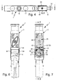
- Nachfolgend wird die Erfindung anhand der beiliegenden Zeichnung näher erläutert. In dieser zeigen:
- Figur 1
- eine bevorzugte Ausführungsform der erfindungsgemäßen Ventilanordnung in einer perspektivischen Darstellung,
- Figur 2
- die Ventilanordnung aus
Figur 1 im voneinander getrennten Zustand von Ventil, Ventilträger und Steckvorrichtung, - Figur 3
- eine Seitenansicht der Ventilanordnung mit Blickrichtung gemäß Pfeil III aus
Figur 1 , - Figur 4
- eine Unteransicht der Ventilanordnung mit Blickrichtung gemäß Pfeil IV aus
Figur 3 , - Figur 5
- einen Längsschnitt durch die Ventilanordnung gemäß Schnittlinie V-V aus
Figuren 4 und 7 , - Figur 6
- eine Stirnansicht der Ventilanordnung mit Blickrichtung gemäß Pfeil VI aus
Figur 3 , - Figur 7
- einen Querschnitt durch die Ventilanordnung im Bereich der Tragwand gemäß Schnittlinie VII-VII aus
Figuren 3 und 5 , und - Figur 8
- eine Seitenansicht der in ihre wesentlichen Komponenten zerlegten Ventilanordnung mit Blickrichtung gemäß Pfeil VIII aus
Figur 2 . - Aus der Zeichnung ist eine insgesamt mit Bezugsziffer 1 bezeichnete Ventilanordnung ersichtlich, die als wesentliche Komponenten einen im Wesentlichen platten- oder blockförmigen Ventilträger 2, ein mit dem Ventilträger 2 zu einer Baugruppe kombinierbares Ventil 3 und eine für die elektrische Ansteuerung des Ventils 3 genutzte elektromechanische Steckvorrichtung 4 aufweist.
- Der Ventilträger 2 hat vorzugsweise eine längliche Gestalt mit einer Längsachse 5. Er verfügt über einen mit mehreren internen, zur Fluidführung dienenden Ventilträgerkanälen 6 ausgestatteten, als Kanalkörper 7 bezeichneten Grundkörper, der quer zu der Längsachse 5 zweckmäßigerweise einen im Wesentlichen rechteckigen Querschnitt hat. Zur Einsparung von Material kann er wie abgebildet an verschiedenen Stellen ausgemagert sein.
- An wenigstens einer der beiden in Achsrichtung der Längsachse 5 orientierten Stirnseiten des Kanalkörpers 7 ist ein Tragarm 8 angeordnet, der in Achsrichtung der Längsachse 5 von dem Kanalkörper 7 wegragt. Vorzugsweise ist der Tragarm 8 einstückig mit dem Kanalkörper 7 ausgebildet und besteht insbesondere aus dem gleichen Material wie dieser.
- Eine der quer zur Längsachse 5 orientierten Seitenflächen des Ventilträgers 2 ist als bevorzugt eben gestaltete Bestückungsfläche 12 ausgebildet. Sie hat exemplarisch einen länglich-rechteckigen Umriss und erstreckt sich ununterbrochen über sowohl den Kanalkörper 7 als auch den Tragarm 8 hinweg.
- Das Ventil 3 ist unter Einnahme einer aus
Figuren 1 und3 bis7 ersichtlichen Gebrauchsposition an dem Ventilträger 2 montierbar. In der Gebrauchsposition liegt es mit einer von einer seiner längsseitigen Außenflächen gebildeten Grundfläche 13 zumindest partiell an der Bestückungsfläche 12 an. Exemplarisch ergibt sich ein unmittelbarer Kontakt zwischen Ventil und Ventilträger 2 nur in dem sich am Kanalkörper befindenden ersten Flächenabschnitt 12a der Bestückungsfläche 12, während zu dem an dem Tragarm 8 ausgebildeten zweiten Flächenabschnitt 12b der Bestückungsfläche 12 ein - in der Regel relativ kleiner - Zwischenraum 14 vorhanden sein kann. - Im Innern des Ventils 3 sind mehrere Ventilkanäle 15 ausgebildet. Einige davon münden in dem dem Kanalkörper 7 gegenüberliegenden Bereich der Grundfläche 13 aus, und zwar derart, dass jede dieser Mündungen mit einer von mehreren in dem ersten Flächenabschnitt 12a der Bestückungsfläche 12 angeordneten Kanalmündungen der Ventilträgerkanäle 6 kommuniziert, wenn das Ventil 3 die Gebrauchsposition einnimmt. Bei den Ventilträgerkanälen 6 handelt es sich exemplarisch um einen über eine Anschlussvorrichtung 16 mit einer nicht weiter abgebildeten, insbesondere pneumatischen Druckquelle verbindbaren Speisekanal 6a und zwei, beispielsweise unter Zwischenschaltung von Schalldämpfern 17, mit der Atmosphäre oder einer sonstigen Drucksenke verbindbare Abführkanäle 6b, 6c.
- Das Ventil 3 weist einen mit den Ventilkanälen 15 ausgestatteten Steuerteil 18 auf, in dessen Innern mindestens ein in verschiedenen Schaltstellungen positionierbares Ventilglied 19 angeordnet ist, das in der Lage ist, die mit den Ventilträgerkanälen 6 verbundenen Ventilkanäle 15 in unterschiedlichem Muster mit als Arbeitskanäle 15a, 15b ausgebildeten Ventilkanälen 15 zu verbinden. Die Arbeitskanäle 15a, 15b münden exemplarisch abseits der Grundfläche 13, insbesondere an der der Grundfläche 13 entgegengesetzten Oberseite 23 des Steuerteils 18 aus, wo sie unter Vermittlung von Anschlussvorrichtungen 24 und daran anschließbaren Fluidleitungen mit einem nicht weiter abgebildeten Verbraucher fluidisch verbindbar sind. Der Verbraucher ist beispielsweise ein fluidbetätigter Antrieb.
- Zum Umschalten und wunschgemäßen Positionieren des Ventilgliedes 19 ist das Ventil 3 mit mindestens einer, exemplarisch mit genau einer elektrisch aktivierbaren Betätigungseinrichtung 25 ausgestattet. Die Betätigungseinrichtung 25 schließt sich stirnseitig an das Steuerteil 18 an, so dass sie in der Gebrauchsposition des Ventils 3 den an dem Tragarm 8 ausgebildeten zweiten Flächenabschnitt 12b der Bestückungsfläche 12 überdeckt. Die Betätigungseinrichtung 25 ist beim Ausführungsbeispiel eine Elektromagneteinrichtung, könnte aber beispielsweise auch ein piezoelektrischer Aktuator sein. Der Aktivierungszustand der Betätigungseinrichtung 25 bestimmt die Schaltstellung des Ventilgliedes 19 und mithin den Schaltzustand des Ventils 3.
- Es könnte sich bei dem Ventil 3 um ein elektrisch direkt gesteuertes Ventil handeln. In diesem Fall würde ein durch elektrische Aktivierung antreibbares, bewegliches Aktorelement der Betätigungseinrichtung 25 direkt mechanisch auf das Ventilglied 19 einwirken. Die beim Ausführungsbeispiel realisierte bevorzugte Variante sieht hingegen vor, dass die Betätigungseinrichtung 25 Bestandteil einer Vorsteuerventileinrichtung 26 des Ventils 3 ist, mit deren Hilfe in an sich bekannter Weise eine gesteuerte Fluidbeaufschlagung des Ventilgliedes 19 durchgeführt werden kann, um dessen Schaltstellung zu verändern. Das hierzu verwendete Steuerfluid kann beispielsweise über einen sich teils im Ventilträger 2 und teils im Ventil 3 erstreckenden Vorsteuerkanal 27 von dem Speisekanal 6a abgezweigt werden. Auch eine direkte Einspeisung eines Vorsteuermediums ist möglich.
- Befestigungsmittel 28 ermöglichen ein lösbares Befestigen des Ventils 3 in der Gebrauchsposition am Ventilträger 2. Diese Befestigungsmittel 28 wirken zwischen dem Steuerteil 18 und dem Kanalkörper 7. Exemplarisch beinhalten sie zum einen eine Hakenstruktur 28a und zum anderen eine Schraubverbindung 28b. Die Hakenstruktur 28a weist im Bereich der der Betätigungseinrichtung 25 entgegengesetzten Stirnseite des Ventils 3 angeordnete, ineinander einhakbare Hakenelemente auf, die Schraubverbindung 28b eine das Steuerteil 18 rechtwinkelig zu der Bestückungsfläche 12 durchsetzende Befestigungsschraube 32 und ein im Kanalkörper 7 angeordnetes, exemplarisch in einem separaten Mutterelement 33 ausgebildetes Befestigungsgewinde 34.
- Zur Montage in der Gebrauchsposition wird durch schräges Ansetzen des Ventils 3 an den Ventilträger 2 die Hakenstruktur 28a in gegenseitigen Eingriff gebracht, anschließend wird das Ventil 3 bis zur Anlage an die Bestückungsfläche 12 an den Ventilträger 2 herangeschwenkt, und zum Abschluss wird zur festen Verankerung die Befestigungsschraube 32 in das Befestigungsgewinde 34 eingedreht und dadurch das Ventil 3 dem Ventilträger 2 lösbar fest verspannt.
- Zwischen der Bestückungsfläche 12 und der Grundfläche 13 angeordnete Dichtungsmittel gewährleisten einen leckagefreien Fluidübertritt zwischen Ventilträger 2 und Ventil 3.
- Die elektrische Aktivierung der Betätigungseinrichtung 25 erfolgt von außen her durch eine nicht weiter abgebildete elektronische Steuereinrichtung, die die elektrischen Betätigungssignale über elektrische Leiter 35 in die Ventilanordnung 1 einspeist, wobei die elektrischen Leiter 35 an die eingangs erwähnte Steckvorrichtung 4 angeschlossen sind. Die elektrischen Leiter 35 können in mindestens einem flexiblen Kabel zusammengefasst sein. Sie sind entweder wie abgebildet fest mit der Steckvorrichtung 4 verdrahtet oder können durch geeignete Schnittstellenmittel lösbar an der Steckvorrichtung 4 angebracht sein.
- Die Betätigungseinrichtung 25 weist in einer in der Gebrauchsstellung des Ventils 3 dem am Tragarm 8 angeordneten zweiten Flächenabschnitt 12b der Bestückungsfläche 12 gegenüberliegenden und zugewandten Anschlusszone 36 erste Steckkontaktmittel 37 auf. Die Anschlusszone 36 befindet sich an der dem zweiten Flächenabschnitt 12b zugewandten Außenfläche eines beispielsweise quaderförmigen Grundkörpers 38 der Betätigungseinrichtung 25, von dem die ersten Steckkontaktmittel 37 in Richtung zum Tragarm 8 wegragen. Die ersten Steckkontaktmittel 37 bestehen beim Ausführungsbeispiel aus zwei als Kontaktfahnen ausgebildeten Kontaktelementen 42, die zweckmäßigerweise axial beabstandet auf einer zu der Längsachse 5 parallelen Linie angeordnet sind. Im Innern des Grundkörpers 38 stehen die Kontaktelemente 42 mit den elektrischen Komponenten der Betätigungseinrichtung 25 in elektrischer Verbindung.
- Der Tragarm 8 verfügt über eine den zweiten Flächenabschnitt 12b der Bestückungsfläche 12 aufweisende, bevorzugt plattenförmig ausgebildete Tragwand 43. Der zweite Flächenabschnitt 12b ist von einer der beiden großflächigen Außenflächen der Tragwand 43 gebildet. Ihre in der Normalenrichtung der Bestückungsfläche 12 gemessene Dicke ist wesentlich geringer als diejenige des entsprechend gemessenen Kanalkörpers 7. Auf diese Weise ergibt sich im Bereich der der Bestückungsfläche 12 entgegengesetzten Rückseite der Tragwand 43 ein offener Montagebereich 44, der lediglich durch eine L-förmige Wandfläche begrenzt ist, die durch die Rückseite des Tragarmes 8 und die sich an den Tragarm 8 anschließende Stirnfläche 45 des Kanalkörpers 7 gebildet ist.
- Der Montagebereich 44 dient zur Aufnahme der Steckvorrichtung 4. Selbige ist lösbar an die dem zweiten Flächenabschnitt 12b entgegengesetzte, dem Montagebereich 44 zugewandte Rückseite 46 der Tragwand 43 angesetzt und durch Schraubverbindungsmittel 47 lösbar direkt an der Tragwand 43 fixiert.
- Die derart fixierte Steckvorrichtung 4 stützt sich mit einer Anschlussfläche 48 an der als Rückseite 46 bezeichneten, dem zweiten Flächeabschnitt 12b abgewandten Fläche der Tragwand 43 ab.
- Die Steckvorrichtung 4 ist mit zweiten Steckkontaktmitteln 52 ausgestattet, die mit den elektrischen Leitern 35 verbunden sind. Sie sind von der Anschlussfläche 48 her zugänglich und beim Ausführungsbeispiel als vertiefte Steckaufnahmen 53 ausgebildet, deren Anzahl und Verteilung derjenigen der vom Ventil 3 wegragenden Kontaktelemente 42 entspricht.
- In der Tragwand 43 ist eine der Anzahl der Kontaktelemente 42 entsprechende Anzahl von Durchbrechungen 54 ausgebildet. Jede Durchbrechung 54 fluchtet mit einem der Kontaktelemente 42, so dass letztere in der Lage sind, bei in Gebrauchsposition befindlichem Ventil 3 durch die Durchbrechungen 54 hindurchzugreifen und in den sich rückseitig an die Tragwand 43 anschließenden Montagebereich 44 hineinzuragen. Dort tauchen sie in jeweils eine der Steckaufnahmen 53 der Steckvorrichtung 4 ein, die ebenfalls fluchtend mit den Durchbrechungen 54 ausgerichtet sind, so dass auf diese Weise eine elektrische Steckverbindung zwischen den zu der Betätigungseinrichtung 25 gehörenden ersten Steckkontaktmitteln 37 und den zur Steckvorrichtung 4 gehörenden zweiten Steckkontaktmitteln 52 hergestellt ist.
- Bei durch die Schraubverbindungsmittel 47 an der Tragwand 43 befestigter Steckvorrichtung 4 kann das Ventil 3 beliebig vom Ventilträger 2 abgenommen oder an den Ventilträger 2 angesetzt werden, wobei jeweils die vorgenannte elektrische Steckverbindung aufgehoben oder hergestellt wird, ohne eine Manipulation an der Steckvorrichtung 4 vornehmen zu müssen.
- Die Schraubverbindungsmittel 47 umfassen in vorteilhafter Weise eine an der Tragwand 43 angeordnete Gewindeöffnung 55 und eine sich an der Steckvorrichtung 4 abstützende Befestigungsschraube 56. Die Gewindeöffnung 55 befindet sich in dem von der Anschlusszone 36 der Betätigungseinrichtung 25 überdeckten Bereich der Tragwand 43 und ist beim Ausführungsbeispiel unmittelbar in der Tragwand 43 ausgebildet. Es handelt sich zweckmäßigerweise um ein mit einem Innengewinde versehenes Durchgangsloch der Tragwand 43.
- Die Befestigungsschraube 56 durchsetzt die Steckvorrichtung 4 in ihrer Höhenrichtung, also rechtwinkelig zu der Anschlussfläche 48, wobei sie sich mit einem Schraubenkopf 57 an der der Anschlussfläche 48 entgegengesetzten rückseitigen Außenfläche 58 des Gehäuses der Steckvorrichtung 4 abstützt und mit einem an der Anschlussfläche 48 herausragenden Gewindeschaft 62 mit der Gewindeöffnung 55 in Gewindeeingriff steht. Durch entsprechendes Festziehen der Befestigungsschraube 56 kann die Steckvorrichtung 4 fest mit der Rückseite 46 der Tragwand 43 verspannt werden.
- Soll trotz aus Kunststoffmaterial bestehender Tragwand 43 eine besonders hohe Festigkeit für das Innengewinde der Gewindeöffnung 55 gewährleistet werden, kann die Gewindeöffnung 55 auch durch einen separaten Gewindekörper bereitgestellt werden, der an oder in der Tragwand 43 befestigt ist. Es kann sich insbesondere um ein bei der Spritzgießherstellung des Ventilträgers 2 vom Kunststoffmaterial umspritztes metallisches Einlegeteil handeln.
- Insbesondere aus
Figur 2 ist ersichtlich, dass die Steckvorrichtung 4 im Bereich ihrer Anschlussfläche 48 vorzugsweise einen rechteckigen Grundriss aufweist. Eine den Durchgriff der Befestigungsschraube 56 ermöglichende, die Steckvorrichtung 4 in Höhenrichtung durchsetzende Durchtrittsöffnung 63 tritt insbesondere im Zentrum des rechteckigen Grundrisses der Anschlussfläche 48 aus, so dass die Gewindeöffnung 55 direkt mit ihr fluchtet. - Wie man wiederum der
Figur 2 ersehen kann, ist die Gewindeöffnung 55 zweckmäßigerweise abstandsmittig zwischen den beim Ausführungsbeispiel vorhandenen zwei Durchbrechungen 54 der Tragwand 43 angeordnet. - Aufgrund des Umstandes, dass der Montagebereich 44 auf der der Tragwand 43 gegenüberliegenden Seite offen ist, kann von dorther problemlos ein Schraubwerkzeug an den Schraubenkopf 57 zur Betätigung der Befestigungsschraube 56 angesetzt werden. Auch das Ansetzen der Steckvorrichtung 4 an die Tragwand 43 sowie ihr bedarfsgemäßes Abnehmen von der Tragwand 43 wird auf diese Weise vereinfacht, zumal zweckmäßigerweise auch noch die der Stirnfläche 45 gegenüberliegende Seite des Montagebereichtes 44 offen ist und dadurch ein problemloser seitlicher Abgang der elektrischen Leiter 45 realisierbar ist.
- Da die Schraubverbindung 47 nur zwischen der Steckvorrichtung 4 und der Tragwand 43 stattfindet, kann direkt am Ventil 3 eine das Einschrauben der Befestigungsschraube 56 ermöglichende Gewindeöffnung entfallen. Sie ist beim Ausführungsbeispiel aus Kostengründen eingespart worden.
- Insbesondere um die Festigkeit der Tragwand 43 zu erhöhen, aber auch um die Position der montierten Steckvorrichtung 4 zu stabilisieren, verfügt der Tragarm 8 zweckmäßigerweise an den beiden längsseitigen Seitenrändern der Tragwand 43 über je einen von der Bestückungsfläche 12 wegragenden Stabilisierungsschenkel 64. Auf diese Weise hat der Tragarm 8 im Bereich der Stabilisierungsschenkel 64 einen U-förmigen Querschnitt mit dem Montagebereich 44 zugewandter U-Öffnung. Exemplarisch erstrecken sich die Stabilisierungsschenkel 64 über die gesamte Länge der Tragwand 43, sie können jedoch auch kürzer ausfallen. Von Vorteil ist außerdem, wenn die rechtwinkelig zur Bestückungsfläche 12 gemessene Höhe der Stabilisierungsschenkel 64 mit zunehmender Entfernung vom Kanalkörper 7 abnimmt. Es kann insbesondere ein abgerundeter Randverlauf vorliegen.
- Die Stabilisierungschenkel 64 stützen sich zweckmäßigerweise einenends an dem Kanalkörper 7 ab, wobei sie zweckmäßigerweise einstückig mit dem letzteren ausgeführt sind. Gemeinsam mit den beiden Stabilisierungsschenkeln 64 begrenzt die Tragwand 43 in dem Montagebereich 44 einen Zwischenraum, in den die montierte Steckvorrichtung 4 zumindest teilweise eintaucht. Sie erfährt dadurch eine seitliche Stabilisierung und Abstützung, so dass Beschädigungen der ersten und zweiten Steckkontaktmittel 37, 52 vermieden werden, falls durch externe Einflüsse eine unerwünschte Querkraft in die Steckvorrichtung 4 eingeleitet werden sollte.
- Bei der Steckvorrichtung 4 handelt es sich zweckmäßigerweise um einen üblichen sogenannten Ventilstecker, wie er Verwendung findet, um direkt eine Betätigungseinrichtung eines Ventils zu kontaktieren, in deren Anschlusszone unmittelbar selbst eine Gewindeöffnung zum Einschrauben der Befestigungsschraube 56 ausgebildet ist. Die Steckvorrichtung 4 ist somit vorzugsweise universell verwendbar.
- Exemplarisch ist der Ventilträger 2 zur Bestückung mit nur einem einzigen Ventil 3 ausgebildet. Er könnte jedoch auch mehrere Bestückungsflächen 12 zur gleichzeitigen Montage mehrerer Ventile 3 aufweisen.
- Es besteht ferner die Möglichkeit, den Ventilträger 2, insbesondere an einander entgegengesetzten Stirnseiten, mit jeweils einem Tragarm 8 der geschilderten Art auszustatten, so dass Ventile 3 kontaktierbar sind, die an einander entgegengesetzten Stirnseiten mit je einer Betätigungseinrichtung 25 ausgestattet sind.
- Die Ventilanordnung des Ausführungsbeispiels stellt eine autark nutzbare Ventileinheit dar. Prinzipiell wäre es jedoch möglich, den Ventilträger 2 so auszubilden, dass mindestens einer der Ventilträgerkanäle 6 den Kanalkörper 7 quer durchsetzt, so dass durch Aneinanderreihung mehrerer Ventilträger 2 eine modulare Ventilbaugruppe zusammengesetzt werden kann. Seitens des Ventils 3 besteht der Vorteil, dass es wahlweise als Komponente einer mit integrierten elektrischen Signalverteilungsmitteln ausgestatteten Ventilbaugruppe oder, in Verbindung mit dem beschriebenen Ventilträger 2, als Einzelventil nutzbar ist. Für den Anwender hat dies den Vorteil, dass er für unterschiedliche Anwendungsfälle nur eine Ventilart bereitstellen muss, was entsprechende Einsparungen in der Logistik, in der Lagerhaltung, im Reparaturfall und bei der Produktschulung mit sich bringt.
Claims (16)
- Ventilanordnung, mit mindestens einem Ventilträger (2), der eine Bestückungsfläche (12) aufweist und in dem mindestens ein zur Bestückungsfläche (12) ausmündender Ventilträgerkanal (6) verläuft, mit mindestens einem Ventil (3), das mindestens eine elektrisch aktivierbare Betätigungs-einrichtung (25) mit in einer Anschlusszone (36) außen am Ventil (3) angeordneten ersten Steckkontaktmitteln (37) aufweist und das derart in einer Gebrauchsposition an der Bestückungsfläche (12) montierbar ist, dass mindestens ein in ihm verlaufender Ventilkanal (15) mit mindestens einem Ventilträgerkanal (6) verbunden ist und zugleich die ersten Steckkontaktmittel (37) mit zweiten Steckkontaktmitteln (52) in Eingriff stehen, die Bestandteile einer mit elektrischen Leitern (35) verbundenen oder verbindbaren elektromechanischen Steckvorrichtung (4) sind, die auf der der Bestückungsfläche (12) entgegengesetzten Seite eines Wandabschnittes des Ventilträgers (2) am Ventilträger (2) fixiert ist, dadurch gekennzeichnet, dass der Wandabschnitt als die Steckvorrichtung (4) unmittelbar tragende Tragwand (43) ausgebildet ist, an deren von der Bestückungsfläche (12) abgewandte Rückseite (46) die Steckvorrichtung (4) angesetzt ist und die in dem in der Gebrauchsposition des Ventils (3) von dessen Anschlusszone (36) überdeckten Bereich mindestens eine Gewindeöffnung (55) aufweist, in die eine Befestigungsschraube (56) eingreift, mittels der die Steckvorrichtung (4) an der Tragwand (43) gehalten ist.
- Ventilanordnung nach Anspruch 1, dadurch gekennzeichnet, dass die Tragwand (43) ein einstückiger Bestandteil des Ventilträgers (2) ist und zweckmäßigerweise aus einem Kunststoffmaterial besteht.
- Ventilanordnung nach Anspruch 1 oder 2, dadurch gekennzeichnet, dass das Gewinde der die Tragwand (43) zweckmäßigerweise durchsetzenden Gewindeöffnung (55) direkt in der Tragwand (43) selbst ausgebildet ist.
- Ventilanordnung nach einem der Ansprüche 1 bis 3, dadurch gekennzeichnet, dass die Befestigungsschraube (56) die Steckvorrichtung (4) durchsetzt, insbesondere im Zentrum des bevorzugten rechteckigen Grundrisses der Steckvorrichtung (4), wobei sie einen die Steckvorrichtung (4) beaufschlagenden Schraubenkopf (57) und einen in die Gewindeöffnung (55) eingeschraubten Gewindeschaft (62) aufweist.
- Ventilanordnung nach einem der Ansprüche 1 bis 4, dadurch gekennzeichnet, dass die ersten Steckkontaktmittel (37) bei in Gebrauchsposition befindlichen Ventil (3) durch die Tragwand (43) hindurchgreifen und zur Kontaktierung der zweiten Steckkontaktmittel (52) in die an der Rückseite (46) der Tragwand (43) angeordnete Steckvorrichtung (4) eintauchen.
- Ventilanordnung nach einem der Ansprüche 1 bis 5, dadurch gekennzeichnet, dass die ersten Steckkontaktmittel (37) mehrere in der Anschlusszone (36) von dem Ventil (3) wegragende, insbesondere als Kontaktfahnen ausgebildete Kontaktelemente (42) aufweisen und die Tragwand (43) für den Durchgriff der Kontaktelemente (42) jeweils eine Durchbrechung (54) aufweist, wobei die Gewindeöffnung (55) zweckmäßigerweise zwischen den Durchbrechungen (54) angeordnet ist.
- Ventilanordnung nach einem der Ansprüche 1 bis 6, dadurch gekennzeichnet, dass die Tragwand (43) rückseitig einen Montagebereich (44) begrenzt, in dem die an der Tragwand (43) fixierte Steckvorrichtung (4) angeordnet ist und der zumindest an der der Tragwand (43) gegenüberliegenden Seite offen ist.
- Ventilanordnung nach einem der Ansprüche 1 bis 7, dadurch gekennzeichnet, dass die Tragwand (43) Bestandteil eines von einem den mindestens einen Ventilträgerkanal (6) enthaltenden Kanalkörper (7) der Ventilträgers (2) wegragenden, frei endenden Tragarmes (8) ist.
- Ventilanordnung nach Anspruch 8, dadurch gekennzeichnet, dass der Tragarm (8) über wenigstens einen Teil seiner Länge einen U-förmigen Querschnitt aufweist, indem von den beiden längsseitigen Rändern der Tragwand (43) jeweils ein Stabilisierungsschenkel (64) in die der Bestückungsfläche (12) entgegengesetzte Richtung wegragt.
- Ventilanordnung nach Anspruch 9, dadurch gekennzeichnet, dass sich die Stabilisierungsschenkel (64) an dem Kanalkörper (7) abstützen, insbesondere indem sie einstückig mit dem Kanalkörper (7) ausgebildet sind.
- Ventilanordnung nach Anspruch 9 oder 10, dadurch gekennzeichnet, dass die montierte Steckvorrichtung (4) zwischen die beiden Stabilisierungsschenkel (64) eintaucht und zweckmäßigerweise von den Stabilisierungselementen (64) seitlich abgestützt ist.
- Ventilanordnung nach einem der Ansprüche 1 bis 11, dadurch gekennzeichnet, dass das Ventil (3) im Bereich der Anschlusszone (36) gewindeöffnungslos und insbesondere mit einer geschlossenen Oberfläche ausgebildet ist.
- Ventilanordnung nach einem der Ansprüche 1 bis 12, dadurch gekennzeichnet, dass das Ventil (3) in der Gebrauchsposition ausschließlich durch Befestigungsmittel (28) am Ventilträger (2) fixiert ist, die weder direkt an der Betätigungseinrichtung (25) noch an der Tragwand (43) angreifen.
- Ventilanordnung nach einem der Ansprüche 1 bis 13, dadurch gekennzeichnet, dass der Ventilträger (2) zur Bestückung mit stets nur einem einzigen Ventil (3) ausgebildet ist.
- Ventilanordnung nach einem der Ansprüche 1 bis 14, dadurch gekennzeichnet, dass an der Bestückungsfläche (12) mehrere Ventilträgerkanäle (6) ausmünden, von denen wenigstens einer ein mit einer Druckquelle verbindbarer Speisekanal (6a) und wenigstens ein weiterer ein mit einer Drucksenke verbindbarer Abführkanal (6b, 6c) ist, und die jeweils mit einem Ventilkanal (15) des in Gebrauchsposition befindlichen Ventils (3) verbunden sind, wobei mindestens ein weiterer Ventilkanal (15, 15a, 15b) ein mit einem anzusteuernden Verbraucher verbindbarer Arbeitskanal ist.
- Ventilanordnung nach einem der Ansprüche 1 bis 15, dadurch gekennzeichnet, dass die Betätigungseinrichtung (25) eine Elektromagneteinrichtung ist, bei der es sich zweckmäßigerweise um einen Bestandteil einer Vorsteuerventileinrichtung (26) des Ventils (3) handelt.
Applications Claiming Priority (1)
| Application Number | Priority Date | Filing Date | Title |
|---|---|---|---|
| DE200910016604 DE102009016604B3 (de) | 2009-04-08 | 2009-04-08 | Ventilanordnung |
Publications (3)
| Publication Number | Publication Date |
|---|---|
| EP2239469A2 true EP2239469A2 (de) | 2010-10-13 |
| EP2239469A3 EP2239469A3 (de) | 2013-12-11 |
| EP2239469B1 EP2239469B1 (de) | 2014-07-16 |
Family
ID=42221171
Family Applications (1)
| Application Number | Title | Priority Date | Filing Date |
|---|---|---|---|
| EP20100001253 Active EP2239469B1 (de) | 2009-04-08 | 2010-02-08 | Ventilanordnung |
Country Status (2)
| Country | Link |
|---|---|
| EP (1) | EP2239469B1 (de) |
| DE (1) | DE102009016604B3 (de) |
Families Citing this family (2)
| Publication number | Priority date | Publication date | Assignee | Title |
|---|---|---|---|---|
| DE102011122518B4 (de) * | 2011-12-29 | 2022-04-07 | Aventics Gmbh | Ventileinheit und Ventilanordnung |
| DE102024111098A1 (de) * | 2024-04-19 | 2025-10-23 | Festo Se & Co. Kg | Adaptermodul für eine Ventileinheit |
Citations (3)
| Publication number | Priority date | Publication date | Assignee | Title |
|---|---|---|---|---|
| DE4444024A1 (de) | 1994-12-10 | 1996-06-13 | Festo Kg | Steuereinrichtung, insbesondere zur Ansteuerung von Ventilen |
| DE10351571A1 (de) | 2002-11-07 | 2004-05-27 | Smc Corp. | Verteilerventil |
| DE102006030039A1 (de) | 2006-06-29 | 2008-01-03 | Festo Ag & Co. | Ventileinrichtung und zugehöriges Mehrwegeventil |
Family Cites Families (3)
| Publication number | Priority date | Publication date | Assignee | Title |
|---|---|---|---|---|
| JP3280004B2 (ja) * | 1999-10-18 | 2002-04-30 | エスエムシー株式会社 | 給電機構付き電磁弁マニホールド |
| US20060225798A1 (en) * | 2005-03-29 | 2006-10-12 | Robert Bordonaro | Integrated expandable gas or fluid distribution system |
| US7938145B2 (en) * | 2006-06-02 | 2011-05-10 | Smc Corporation Of America | Coupler including electrical and pneumatic interfaces |
-
2009
- 2009-04-08 DE DE200910016604 patent/DE102009016604B3/de not_active Expired - Fee Related
-
2010
- 2010-02-08 EP EP20100001253 patent/EP2239469B1/de active Active
Patent Citations (3)
| Publication number | Priority date | Publication date | Assignee | Title |
|---|---|---|---|---|
| DE4444024A1 (de) | 1994-12-10 | 1996-06-13 | Festo Kg | Steuereinrichtung, insbesondere zur Ansteuerung von Ventilen |
| DE10351571A1 (de) | 2002-11-07 | 2004-05-27 | Smc Corp. | Verteilerventil |
| DE102006030039A1 (de) | 2006-06-29 | 2008-01-03 | Festo Ag & Co. | Ventileinrichtung und zugehöriges Mehrwegeventil |
Also Published As
| Publication number | Publication date |
|---|---|
| EP2239469A3 (de) | 2013-12-11 |
| DE102009016604B3 (de) | 2010-07-01 |
| EP2239469B1 (de) | 2014-07-16 |
Similar Documents
| Publication | Publication Date | Title |
|---|---|---|
| EP2047111B1 (de) | Modulare ventilanordnung für unterschiedliche durchflusskategorien | |
| EP1059458B1 (de) | Fluidtechnisches Steuergerät | |
| DE3814485C2 (de) | ||
| EP3063833B1 (de) | Anschlusszeile für eine anschlussvorrichtung und verfahren zur herstellung einer anschlusszeile für eine anschlussvorrichtung | |
| DE10013192B4 (de) | Ventilanordnung | |
| EP1013940B1 (de) | Ventilanordnung | |
| EP0658463A2 (de) | Ventilsteuervorrichtung | |
| DE102005015200A1 (de) | Kopplungsventil | |
| DE10351571B4 (de) | Verteilerventil | |
| DE102011100327B3 (de) | Fluidtechnische Baugruppe | |
| EP2032859B1 (de) | Ventileinrichtung | |
| EP2239469B1 (de) | Ventilanordnung | |
| EP2110562B1 (de) | Ventilanordnung | |
| EP2354563B1 (de) | Ventilanordnung | |
| EP2738396A1 (de) | Ventilanordnung | |
| EP2140183B1 (de) | Piezoelektrische ventilbatterie | |
| EP2255094B1 (de) | Ventilbatterie | |
| EP1345483B1 (de) | Kontaktierungseinrichtung für Ventilantriebe und damit ausgestattete Ventilanordnung | |
| DE19937974B4 (de) | Ventileinrichtung | |
| EP2412985B1 (de) | Fluidverteileranordnung | |
| DE102009048018A1 (de) | Hochdruckverteilerblock einer Kühl-Schmierstoffversorgungseinrichtung | |
| EP1218656A1 (de) | Ventilanordnung | |
| EP2110561B1 (de) | Elektrische Anschlusseinheit und damit ausgestattete Ventilanordnung | |
| EP2746592B1 (de) | Ventilanordnung | |
| EP2746597B1 (de) | Ventilanordnung |
Legal Events
| Date | Code | Title | Description |
|---|---|---|---|
| PUAI | Public reference made under article 153(3) epc to a published international application that has entered the european phase |
Free format text: ORIGINAL CODE: 0009012 |
|
| AK | Designated contracting states |
Kind code of ref document: A2 Designated state(s): AT BE BG CH CY CZ DE DK EE ES FI FR GB GR HR HU IE IS IT LI LT LU LV MC MK MT NL NO PL PT RO SE SI SK SM TR |
|
| AX | Request for extension of the european patent |
Extension state: AL BA RS |
|
| PUAL | Search report despatched |
Free format text: ORIGINAL CODE: 0009013 |
|
| AK | Designated contracting states |
Kind code of ref document: A3 Designated state(s): AT BE BG CH CY CZ DE DK EE ES FI FR GB GR HR HU IE IS IT LI LT LU LV MC MK MT NL NO PL PT RO SE SI SK SM TR |
|
| AX | Request for extension of the european patent |
Extension state: AL BA RS |
|
| RIC1 | Information provided on ipc code assigned before grant |
Ipc: F15B 13/08 20060101AFI20131101BHEP |
|
| 17P | Request for examination filed |
Effective date: 20131129 |
|
| RBV | Designated contracting states (corrected) |
Designated state(s): AT BE BG CH CY CZ DE DK EE ES FI FR GB GR HR HU IE IS IT LI LT LU LV MC MK MT NL NO PL PT RO SE SI SK SM TR |
|
| GRAP | Despatch of communication of intention to grant a patent |
Free format text: ORIGINAL CODE: EPIDOSNIGR1 |
|
| INTG | Intention to grant announced |
Effective date: 20140227 |
|
| GRAS | Grant fee paid |
Free format text: ORIGINAL CODE: EPIDOSNIGR3 |
|
| GRAA | (expected) grant |
Free format text: ORIGINAL CODE: 0009210 |
|
| AK | Designated contracting states |
Kind code of ref document: B1 Designated state(s): AT BE BG CH CY CZ DE DK EE ES FI FR GB GR HR HU IE IS IT LI LT LU LV MC MK MT NL NO PL PT RO SE SI SK SM TR |
|
| REG | Reference to a national code |
Ref country code: GB Ref legal event code: FG4D Free format text: NOT ENGLISH |
|
| REG | Reference to a national code |
Ref country code: CH Ref legal event code: EP |
|
| REG | Reference to a national code |
Ref country code: IE Ref legal event code: FG4D Free format text: LANGUAGE OF EP DOCUMENT: GERMAN |
|
| REG | Reference to a national code |
Ref country code: AT Ref legal event code: REF Ref document number: 677838 Country of ref document: AT Kind code of ref document: T Effective date: 20140815 |
|
| REG | Reference to a national code |
Ref country code: DE Ref legal event code: R096 Ref document number: 502010007431 Country of ref document: DE Effective date: 20140828 |
|
| REG | Reference to a national code |
Ref country code: NL Ref legal event code: VDEP Effective date: 20140716 |
|
| REG | Reference to a national code |
Ref country code: LT Ref legal event code: MG4D |
|
| PG25 | Lapsed in a contracting state [announced via postgrant information from national office to epo] |
Ref country code: NO Free format text: LAPSE BECAUSE OF FAILURE TO SUBMIT A TRANSLATION OF THE DESCRIPTION OR TO PAY THE FEE WITHIN THE PRESCRIBED TIME-LIMIT Effective date: 20141016 Ref country code: PT Free format text: LAPSE BECAUSE OF FAILURE TO SUBMIT A TRANSLATION OF THE DESCRIPTION OR TO PAY THE FEE WITHIN THE PRESCRIBED TIME-LIMIT Effective date: 20141117 Ref country code: LT Free format text: LAPSE BECAUSE OF FAILURE TO SUBMIT A TRANSLATION OF THE DESCRIPTION OR TO PAY THE FEE WITHIN THE PRESCRIBED TIME-LIMIT Effective date: 20140716 Ref country code: BG Free format text: LAPSE BECAUSE OF FAILURE TO SUBMIT A TRANSLATION OF THE DESCRIPTION OR TO PAY THE FEE WITHIN THE PRESCRIBED TIME-LIMIT Effective date: 20141016 Ref country code: FI Free format text: LAPSE BECAUSE OF FAILURE TO SUBMIT A TRANSLATION OF THE DESCRIPTION OR TO PAY THE FEE WITHIN THE PRESCRIBED TIME-LIMIT Effective date: 20140716 Ref country code: ES Free format text: LAPSE BECAUSE OF FAILURE TO SUBMIT A TRANSLATION OF THE DESCRIPTION OR TO PAY THE FEE WITHIN THE PRESCRIBED TIME-LIMIT Effective date: 20140716 Ref country code: SE Free format text: LAPSE BECAUSE OF FAILURE TO SUBMIT A TRANSLATION OF THE DESCRIPTION OR TO PAY THE FEE WITHIN THE PRESCRIBED TIME-LIMIT Effective date: 20140716 Ref country code: GR Free format text: LAPSE BECAUSE OF FAILURE TO SUBMIT A TRANSLATION OF THE DESCRIPTION OR TO PAY THE FEE WITHIN THE PRESCRIBED TIME-LIMIT Effective date: 20141017 |
|
| PG25 | Lapsed in a contracting state [announced via postgrant information from national office to epo] |
Ref country code: CY Free format text: LAPSE BECAUSE OF FAILURE TO SUBMIT A TRANSLATION OF THE DESCRIPTION OR TO PAY THE FEE WITHIN THE PRESCRIBED TIME-LIMIT Effective date: 20140716 Ref country code: LV Free format text: LAPSE BECAUSE OF FAILURE TO SUBMIT A TRANSLATION OF THE DESCRIPTION OR TO PAY THE FEE WITHIN THE PRESCRIBED TIME-LIMIT Effective date: 20140716 Ref country code: PL Free format text: LAPSE BECAUSE OF FAILURE TO SUBMIT A TRANSLATION OF THE DESCRIPTION OR TO PAY THE FEE WITHIN THE PRESCRIBED TIME-LIMIT Effective date: 20140716 Ref country code: NL Free format text: LAPSE BECAUSE OF FAILURE TO SUBMIT A TRANSLATION OF THE DESCRIPTION OR TO PAY THE FEE WITHIN THE PRESCRIBED TIME-LIMIT Effective date: 20140716 Ref country code: IS Free format text: LAPSE BECAUSE OF FAILURE TO SUBMIT A TRANSLATION OF THE DESCRIPTION OR TO PAY THE FEE WITHIN THE PRESCRIBED TIME-LIMIT Effective date: 20141116 |
|
| REG | Reference to a national code |
Ref country code: DE Ref legal event code: R097 Ref document number: 502010007431 Country of ref document: DE |
|
| PG25 | Lapsed in a contracting state [announced via postgrant information from national office to epo] |
Ref country code: SK Free format text: LAPSE BECAUSE OF FAILURE TO SUBMIT A TRANSLATION OF THE DESCRIPTION OR TO PAY THE FEE WITHIN THE PRESCRIBED TIME-LIMIT Effective date: 20140716 Ref country code: RO Free format text: LAPSE BECAUSE OF FAILURE TO SUBMIT A TRANSLATION OF THE DESCRIPTION OR TO PAY THE FEE WITHIN THE PRESCRIBED TIME-LIMIT Effective date: 20140716 Ref country code: EE Free format text: LAPSE BECAUSE OF FAILURE TO SUBMIT A TRANSLATION OF THE DESCRIPTION OR TO PAY THE FEE WITHIN THE PRESCRIBED TIME-LIMIT Effective date: 20140716 Ref country code: DK Free format text: LAPSE BECAUSE OF FAILURE TO SUBMIT A TRANSLATION OF THE DESCRIPTION OR TO PAY THE FEE WITHIN THE PRESCRIBED TIME-LIMIT Effective date: 20140716 Ref country code: CZ Free format text: LAPSE BECAUSE OF FAILURE TO SUBMIT A TRANSLATION OF THE DESCRIPTION OR TO PAY THE FEE WITHIN THE PRESCRIBED TIME-LIMIT Effective date: 20140716 |
|
| PLBE | No opposition filed within time limit |
Free format text: ORIGINAL CODE: 0009261 |
|
| STAA | Information on the status of an ep patent application or granted ep patent |
Free format text: STATUS: NO OPPOSITION FILED WITHIN TIME LIMIT |
|
| 26N | No opposition filed |
Effective date: 20150417 |
|
| PG25 | Lapsed in a contracting state [announced via postgrant information from national office to epo] |
Ref country code: BE Free format text: LAPSE BECAUSE OF NON-PAYMENT OF DUE FEES Effective date: 20150228 |
|
| PG25 | Lapsed in a contracting state [announced via postgrant information from national office to epo] |
Ref country code: LU Free format text: LAPSE BECAUSE OF FAILURE TO SUBMIT A TRANSLATION OF THE DESCRIPTION OR TO PAY THE FEE WITHIN THE PRESCRIBED TIME-LIMIT Effective date: 20150208 |
|
| REG | Reference to a national code |
Ref country code: CH Ref legal event code: PL |
|
| PG25 | Lapsed in a contracting state [announced via postgrant information from national office to epo] |
Ref country code: MC Free format text: LAPSE BECAUSE OF FAILURE TO SUBMIT A TRANSLATION OF THE DESCRIPTION OR TO PAY THE FEE WITHIN THE PRESCRIBED TIME-LIMIT Effective date: 20140716 Ref country code: CH Free format text: LAPSE BECAUSE OF NON-PAYMENT OF DUE FEES Effective date: 20150228 Ref country code: LI Free format text: LAPSE BECAUSE OF NON-PAYMENT OF DUE FEES Effective date: 20150228 |
|
| REG | Reference to a national code |
Ref country code: IE Ref legal event code: MM4A |
|
| PG25 | Lapsed in a contracting state [announced via postgrant information from national office to epo] |
Ref country code: SI Free format text: LAPSE BECAUSE OF FAILURE TO SUBMIT A TRANSLATION OF THE DESCRIPTION OR TO PAY THE FEE WITHIN THE PRESCRIBED TIME-LIMIT Effective date: 20140716 |
|
| PG25 | Lapsed in a contracting state [announced via postgrant information from national office to epo] |
Ref country code: IE Free format text: LAPSE BECAUSE OF NON-PAYMENT OF DUE FEES Effective date: 20150208 |
|
| REG | Reference to a national code |
Ref country code: FR Ref legal event code: PLFP Year of fee payment: 7 |
|
| REG | Reference to a national code |
Ref country code: AT Ref legal event code: MM01 Ref document number: 677838 Country of ref document: AT Kind code of ref document: T Effective date: 20150208 |
|
| PG25 | Lapsed in a contracting state [announced via postgrant information from national office to epo] |
Ref country code: AT Free format text: LAPSE BECAUSE OF NON-PAYMENT OF DUE FEES Effective date: 20150208 |
|
| PG25 | Lapsed in a contracting state [announced via postgrant information from national office to epo] |
Ref country code: MT Free format text: LAPSE BECAUSE OF FAILURE TO SUBMIT A TRANSLATION OF THE DESCRIPTION OR TO PAY THE FEE WITHIN THE PRESCRIBED TIME-LIMIT Effective date: 20140716 |
|
| REG | Reference to a national code |
Ref country code: FR Ref legal event code: PLFP Year of fee payment: 8 |
|
| PG25 | Lapsed in a contracting state [announced via postgrant information from national office to epo] |
Ref country code: SM Free format text: LAPSE BECAUSE OF FAILURE TO SUBMIT A TRANSLATION OF THE DESCRIPTION OR TO PAY THE FEE WITHIN THE PRESCRIBED TIME-LIMIT Effective date: 20140716 Ref country code: HU Free format text: LAPSE BECAUSE OF FAILURE TO SUBMIT A TRANSLATION OF THE DESCRIPTION OR TO PAY THE FEE WITHIN THE PRESCRIBED TIME-LIMIT; INVALID AB INITIO Effective date: 20100208 |
|
| PG25 | Lapsed in a contracting state [announced via postgrant information from national office to epo] |
Ref country code: HR Free format text: LAPSE BECAUSE OF FAILURE TO SUBMIT A TRANSLATION OF THE DESCRIPTION OR TO PAY THE FEE WITHIN THE PRESCRIBED TIME-LIMIT Effective date: 20140716 |
|
| PG25 | Lapsed in a contracting state [announced via postgrant information from national office to epo] |
Ref country code: TR Free format text: LAPSE BECAUSE OF FAILURE TO SUBMIT A TRANSLATION OF THE DESCRIPTION OR TO PAY THE FEE WITHIN THE PRESCRIBED TIME-LIMIT Effective date: 20140716 |
|
| REG | Reference to a national code |
Ref country code: FR Ref legal event code: PLFP Year of fee payment: 9 |
|
| PG25 | Lapsed in a contracting state [announced via postgrant information from national office to epo] |
Ref country code: MK Free format text: LAPSE BECAUSE OF FAILURE TO SUBMIT A TRANSLATION OF THE DESCRIPTION OR TO PAY THE FEE WITHIN THE PRESCRIBED TIME-LIMIT Effective date: 20140716 |
|
| REG | Reference to a national code |
Ref country code: DE Ref legal event code: R082 Ref document number: 502010007431 Country of ref document: DE Representative=s name: PATENTANWAELTE MAGENBAUER & KOLLEGEN PARTNERSC, DE Ref country code: DE Ref legal event code: R081 Ref document number: 502010007431 Country of ref document: DE Owner name: FESTO SE & CO. KG, DE Free format text: FORMER OWNER: FESTO AG & CO. KG, 73734 ESSLINGEN, DE Ref country code: DE Ref legal event code: R081 Ref document number: 502010007431 Country of ref document: DE Owner name: FESTO AG & CO. KG, DE Free format text: FORMER OWNER: FESTO AG & CO. KG, 73734 ESSLINGEN, DE |
|
| PGFP | Annual fee paid to national office [announced via postgrant information from national office to epo] |
Ref country code: IT Payment date: 20200221 Year of fee payment: 11 Ref country code: GB Payment date: 20200225 Year of fee payment: 11 |
|
| PGFP | Annual fee paid to national office [announced via postgrant information from national office to epo] |
Ref country code: FR Payment date: 20200220 Year of fee payment: 11 |
|
| GBPC | Gb: european patent ceased through non-payment of renewal fee |
Effective date: 20210208 |
|
| PG25 | Lapsed in a contracting state [announced via postgrant information from national office to epo] |
Ref country code: FR Free format text: LAPSE BECAUSE OF NON-PAYMENT OF DUE FEES Effective date: 20210228 Ref country code: GB Free format text: LAPSE BECAUSE OF NON-PAYMENT OF DUE FEES Effective date: 20210208 |
|
| PG25 | Lapsed in a contracting state [announced via postgrant information from national office to epo] |
Ref country code: IT Free format text: LAPSE BECAUSE OF NON-PAYMENT OF DUE FEES Effective date: 20210208 |
|
| P01 | Opt-out of the competence of the unified patent court (upc) registered |
Effective date: 20230623 |
|
| PGFP | Annual fee paid to national office [announced via postgrant information from national office to epo] |
Ref country code: DE Payment date: 20260129 Year of fee payment: 17 |