EP2239451A1 - A fuel injector for internal combustion engines - Google Patents
A fuel injector for internal combustion engines Download PDFInfo
- Publication number
- EP2239451A1 EP2239451A1 EP09156590A EP09156590A EP2239451A1 EP 2239451 A1 EP2239451 A1 EP 2239451A1 EP 09156590 A EP09156590 A EP 09156590A EP 09156590 A EP09156590 A EP 09156590A EP 2239451 A1 EP2239451 A1 EP 2239451A1
- Authority
- EP
- European Patent Office
- Prior art keywords
- cut
- atomizer
- section
- longitudinal bore
- spindle
- Prior art date
- Legal status (The legal status is an assumption and is not a legal conclusion. Google has not performed a legal analysis and makes no representation as to the accuracy of the status listed.)
- Granted
Links
Images


Classifications
-
- F—MECHANICAL ENGINEERING; LIGHTING; HEATING; WEAPONS; BLASTING
- F02—COMBUSTION ENGINES; HOT-GAS OR COMBUSTION-PRODUCT ENGINE PLANTS
- F02M—SUPPLYING COMBUSTION ENGINES IN GENERAL WITH COMBUSTIBLE MIXTURES OR CONSTITUENTS THEREOF
- F02M61/00—Fuel-injectors not provided for in groups F02M39/00 - F02M57/00 or F02M67/00
- F02M61/16—Details not provided for in, or of interest apart from, the apparatus of groups F02M61/02 - F02M61/14
- F02M61/18—Injection nozzles, e.g. having valve seats; Details of valve member seated ends, not otherwise provided for
- F02M61/1806—Injection nozzles, e.g. having valve seats; Details of valve member seated ends, not otherwise provided for characterised by the arrangement of discharge orifices, e.g. orientation or size
- F02M61/182—Discharge orifices being situated in different transversal planes with respect to valve member direction of movement
-
- F—MECHANICAL ENGINEERING; LIGHTING; HEATING; WEAPONS; BLASTING
- F02—COMBUSTION ENGINES; HOT-GAS OR COMBUSTION-PRODUCT ENGINE PLANTS
- F02M—SUPPLYING COMBUSTION ENGINES IN GENERAL WITH COMBUSTIBLE MIXTURES OR CONSTITUENTS THEREOF
- F02M61/00—Fuel-injectors not provided for in groups F02M39/00 - F02M57/00 or F02M67/00
- F02M61/04—Fuel-injectors not provided for in groups F02M39/00 - F02M57/00 or F02M67/00 having valves, e.g. having a plurality of valves in series
- F02M61/042—The valves being provided with fuel passages
-
- F—MECHANICAL ENGINEERING; LIGHTING; HEATING; WEAPONS; BLASTING
- F02—COMBUSTION ENGINES; HOT-GAS OR COMBUSTION-PRODUCT ENGINE PLANTS
- F02M—SUPPLYING COMBUSTION ENGINES IN GENERAL WITH COMBUSTIBLE MIXTURES OR CONSTITUENTS THEREOF
- F02M61/00—Fuel-injectors not provided for in groups F02M39/00 - F02M57/00 or F02M67/00
- F02M61/04—Fuel-injectors not provided for in groups F02M39/00 - F02M57/00 or F02M67/00 having valves, e.g. having a plurality of valves in series
- F02M61/06—Fuel-injectors not provided for in groups F02M39/00 - F02M57/00 or F02M67/00 having valves, e.g. having a plurality of valves in series the valves being furnished at seated ends with pintle or plug shaped extensions
-
- F—MECHANICAL ENGINEERING; LIGHTING; HEATING; WEAPONS; BLASTING
- F02—COMBUSTION ENGINES; HOT-GAS OR COMBUSTION-PRODUCT ENGINE PLANTS
- F02M—SUPPLYING COMBUSTION ENGINES IN GENERAL WITH COMBUSTIBLE MIXTURES OR CONSTITUENTS THEREOF
- F02M61/00—Fuel-injectors not provided for in groups F02M39/00 - F02M57/00 or F02M67/00
- F02M61/04—Fuel-injectors not provided for in groups F02M39/00 - F02M57/00 or F02M67/00 having valves, e.g. having a plurality of valves in series
- F02M61/10—Other injectors with elongated valve bodies, i.e. of needle-valve type
-
- F—MECHANICAL ENGINEERING; LIGHTING; HEATING; WEAPONS; BLASTING
- F02—COMBUSTION ENGINES; HOT-GAS OR COMBUSTION-PRODUCT ENGINE PLANTS
- F02M—SUPPLYING COMBUSTION ENGINES IN GENERAL WITH COMBUSTIBLE MIXTURES OR CONSTITUENTS THEREOF
- F02M61/00—Fuel-injectors not provided for in groups F02M39/00 - F02M57/00 or F02M67/00
- F02M61/16—Details not provided for in, or of interest apart from, the apparatus of groups F02M61/02 - F02M61/14
- F02M61/18—Injection nozzles, e.g. having valve seats; Details of valve member seated ends, not otherwise provided for
- F02M61/1866—Valve seats or member ends having multiple cones
-
- F—MECHANICAL ENGINEERING; LIGHTING; HEATING; WEAPONS; BLASTING
- F02—COMBUSTION ENGINES; HOT-GAS OR COMBUSTION-PRODUCT ENGINE PLANTS
- F02M—SUPPLYING COMBUSTION ENGINES IN GENERAL WITH COMBUSTIBLE MIXTURES OR CONSTITUENTS THEREOF
- F02M61/00—Fuel-injectors not provided for in groups F02M39/00 - F02M57/00 or F02M67/00
- F02M61/16—Details not provided for in, or of interest apart from, the apparatus of groups F02M61/02 - F02M61/14
- F02M61/18—Injection nozzles, e.g. having valve seats; Details of valve member seated ends, not otherwise provided for
- F02M61/1893—Details of valve member ends not covered by groups F02M61/1866 - F02M61/188
Landscapes
- Engineering & Computer Science (AREA)
- Chemical & Material Sciences (AREA)
- Combustion & Propulsion (AREA)
- Mechanical Engineering (AREA)
- General Engineering & Computer Science (AREA)
- Fuel-Injection Apparatus (AREA)
Abstract
- a housing (16),
- a valve guide (38) fixed at a lower end of said housing (16), the valve guide (38) having a longitudinal guide bore (44) and a chamber (46) provided with a valve seat (50), said chamber (46) being connected to a fuel supply duct (22,48);
- an atomizer (56) fixed at a lower end of said valve guide (38), the atomizer (56) having a longitudinal bore (80) in flow connection with said chamber (46), the atomizer having a plurality of nozzle bores (82) having inlet openings (84) facing into said longitudinal bore (80);
- a spindle (88) having a valve portion (92) cooperating with said valve seat (50), and a cut-off element (94) extending into said longitudinal bore (80) of the atomizer (56), wherein an upper cut-off section (102) and a lower cut-off section (106) axially spaced apart from each other are defined between the outer surface of the cut-off element (94) and the inner surface of the longitudinal bore (80), cut-off sections (102,106) being both closed in the closed position of the spindle (88), the cut-off element (94) having a central duct (112) in flow connection with the longitudinal bore (80) of the atomizer (56) both above the upper cut-off section (102) and below the lower cut-off section (106).
Description
- The present invention relates to a fuel injector for internal combustion engines. The invention relates in particular to a fuel injector for large two-stroke internal combustion engines, such as diesel engines for naval propulsion.
- More specifically, the present invention relates to a fuel injector according to the preamble of claim 1, comprising a housing, a valve guide fixed at the lower end of the housing, an atomizer fixed at a lower end of the valve guide and provided with a plurality of nozzle bores, a spindle having a valve portion cooperating with a valve seat of the valve guide, and a cut-off element extending into a longitudinal bore of the atomizer to reduce the volume in fluid connection with the nozzle bores when the spindle is in a closed position.
-
EP-A-052937 - In the solution disclosed in
EP-A-052937 -
W02008/071187 discloses a fuel injector according to the preamble of claim 1, wherein the inlet openings of the nozzle bores of the atomizer are arranged in a first row and in a second row axially spaced apart and separated from each other by a cylindrical sealing portion. A cut-off element extending into a longitudinal bore of the atomizer has a first cylindrical section arranged to open and close the lower row of inlet openings and a second cylindrical section cooperating with a secondary valve seat for closing off the upper row of inlet openings when the valve spindle is closed. - When the valve spindle is open, the lower row of inlet openings is supplied by fuel flowing through a central duct of the cut-off element and the upper row of inlet openings is supplied by fuel flowing in an annular passage defined between the inner wall of the atomizer bore and the outer surface of the cut-off element.
- The object of the present invention is to provide an improved injector which gives greater freedom in the arrangement of the nozzle bores in the atomizer, which ensures that all the nozzle bores are supplied simultaneously and which requires a very short travel of the spindle even if the nozzle bores are arranged in an irregular pattern.
- In accordance with the present invention, this object is achieved by a fuel injector having the features of claim 1.
- In the solution according to the present invention, in the closed position of the spindle the inlet openings of the nozzle bores are all in flow connection with an injection chamber between upper and lower cut-off sections and in the open position of the spindle the upper cut-off section remains closed and the lower cut-off section is opened to establish a flow connection between a central duct of the cut-off element and the injection chamber.
- In the solution according to the present invention all the nozzle bores are simultaneously supplied when the lower cut-off section is opened.
- The arrangement according to the invention provides more freedom in the positioning of the nozzle bores, which can be located at any atomizer height and according to a pattern designed to optimize the spray quality. In accordance with the present invention, the nozzle bores should not necessarily be located in one or two single rows as in the prior art.
- The atomizer of the present invention can be designed with a greater number of nozzle bores, thus improving the spray quality and the fuel combustion, without compromising the strength of the side wall of the atomizer.
- The nozzle bores of the present invention can be axially spaced apart from each other with a relevant height difference even with a very short lift of the spindle. In particular, the lift of the spindle can be shorter than the axial distance between the nozzle bores.
- Further characteristics and advantages of the present invention will become clear in the course of the detailed description which follows, given purely by way of non-limiting example, with reference to the annexed drawings, wherein:
-
figure 1 is an axial cross-section of an injector according to the present invention, -
figures 2 and3 are enlarged views of the part indicated by the arrow II infigure 1 respectively in a closed and open position, -
figure 4 is an enlarged perspective view of the part indicated by the arrow II infigure 1 , -
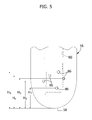
figure 5 is a front view of the part indicated by the arrow V infigure 4 , -
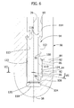
figure 6 is a cross-section corresponding tofigure 2 and showing a second embodiment of the present invention, -
figure 7 is a cross-section taken along line VII-VII offigure 6 . - Referring to
figure 1 , thereference number 10 indicates a fuel injector for diesel engines according to the present invention. Theinjector 10 is intended to be mounted into anelongated cavity 12 formed in thehead 14 of the engine. Theinjector 10 comprises anelongated housing 16 having at its top an enlargedhead 18 protruding outside of thecavity 12 and fixed to theengine head 14 by screws 20 (only one of which is visible infigure 1 ). - In the following description and in the claims the terms "upper", "lower", "top", "bottom" and the like refer to the normal position of use of the
injector 10. It is however envisaged that theinjector 10 could be mounted in a more or less inclined position with respect to a vertical axis. - A
fuel supply duct 22 is formed in thehousing 16 and is connected at its upper end to an opening 24 connected to a fuel supply line (not shown). Athrust element 26 is axially movable along alongitudinal axis 28 inside athrough cavity 30 formed in thehousing 16. Acompression spring 32 acts on atop head 34 of thethrust element 26. The upper end of thecompression spring 32 acts against anadjustment member 36 screwed into an axial hole formed in thehead 18 of theinjector 10. - A
valve guide 38 is fixed at a lower end of thehousing 16. Atubular fixing member 40 engages a threadedportion 42 of thehousing 16 to secure thevalve guide 38 at the front bottom end of thehousing 16. Theguide valve 38 has alongitudinal guide bore 44. Achamber 46 is formed at the lower end of the guide bore 44. Thechamber 46 is in flow connection with afuel supply duct 48 the upper end of which is connected to the lower end of thefuel supply duct 22 of thehousing 16. - With reference to
figures 2 and3 , aconical valve seat 50 is provided at the bottom end of thechamber 46 of thevalve guide 38. Ashort duct 52 extends downwardly of thevalve seat 50 and opens on afront face 54 of thevalve guide 38. - An
atomizer 56 is fixed at a lower end of thevalve guide 38. Theatomizer 56 has a cylindrical body of corrosion-resistant material with a closedbottom end 58. As shown infigure 1 , the lower end of theatomizer 56 extends in a combustion chamber C of the engine. An upperfront face 60 of theatomizer 56 frontally abuts thefront face 54 of thevalve guide 38. A circularupper flange 62 of theatomizer 56 engages a bottomcylindrical surface 64 of theguide valve 38. Avertical pin 66 engages mutually facing openings of thevalve guide 38 and of theatomizer 56 to set theatomizer 56 in a fixed angular position with respect to thevalve guide 38. - The
atomizer 56 is axially fixed to thevalve guide 38 by means of a cup-shaped retaining element 68. Theretaining element 68 and theatomizer 56 have mutually abuttingconical surfaces atomizer 56 projects downwardly through a bottom opening 74 of theretaining element 68. As shown infigure 1 , theretaining element 68 has anupper flange 76 which snap-engages anelastic ring 78 carried at the lower end of thetubular fixing member 40. - With reference to
figures 2 and3 , theatomizer 56 has alongitudinal bore 80 closed at its bottom end. The upper end of thelongitudinal bore 80 is in flow connection with thechamber 46 through theshort duct 52 and thevalve seat 50. A plurality ofnozzle bores 82 is formed in the lateral wall of theatomizer 56. Thenozzle bores 82 have respectiveinner openings 84 facing into thelongitudinal bore 80 andoutlet openings 86 open on the outer surface of theatomizer 56. The inlet openings 84 of at least some of thenozzle bores 82 are axially spaced from each other. In the example shown infigures 4 and5 , thenozzle bores 82 are positioned according to a substantially irregular pattern. - An important feature of the present invention is that the
nozzle bores 82 can be arranged according to any desired pattern. The position of thenozzle bores 82 can be defined as desired by the designer in order to optimize the spray quality. In particular, the number of the nozzle bores 82, the axial position of the inlet andoutlet openings longitudinal axis 28 can be varied as desired for providing an optimal spraying pattern. The fact that the nozzle bores 82 can be placed at any desired axial position is particularly useful in that the total number of nozzle bores arranged within a maximum angle (of e.g. 120°) can be increased without compromising the strength of the side wall of theatomizer 56. The nozzle bores 82 are not necessarily located in parallel rows as in prior art solutions. For instance, as shown infigure 5 , theoutlet openings 86 of the nozzle bores 82 can be located at different atomizer heights H1, H2, H3, H4, H5. - With reference to
figure 1 , aspindle 88 is axially displaceable into thevalve guide 38. Thespindle 88 has acylindrical portion 90 which slidably engages the longitudinal guide bore 44 of thevalve guide 38. As best shown infigures 2 and3 , thespindle 88 has aconical valve portion 92 which cooperates with theconical valve seat 50 of thevalve guide 38. Thespindle 88 is axially movable between a closed position shown infigure 2 and an open position shown infigure 3 . Referring tofigure 1 , the upper end of thespindle 88 abuts against the lower end of thethrust element 26. Thecompression spring 32, through thethrust element 26, biases thespindle 88 in its closed position wherein thevalve portion 92 of thespindle 88 abuts against thevalve seat 50 to shut-off the flow connection between thechamber 46 and thelongitudinal bore 80 of theatomizer 56. - Referring to
figures 2 and3 , thespindle 88 comprises a cut-offelement 94 which extends coaxially below thevalve portion 92 and into thelongitudinal duct 80 of theatomizer 56. The cut-offelement 94 is fixed to or integrally formed with the remaining part of thespindle 88. The outer surface of the cut-offelement 94 has a firstcylindrical sealing portion 96 and a secondcylindrical sealing portion 98 axially spaced apart from each other. Thefirst sealing portion 96 engages with tight fit a firstcylindrical sealing surface 100 of thelongitudinal bore 80 to define an upper cut-offsection 102. Thesecond sealing portion 98 engages with tight fit a secondcylindrical sealing surface 104 of thelongitudinal bore 80 to define a lower cut-offsection 106. The firstcylindrical sealing surface 100 has a diameter greater than that of the secondcylindrical sealing surface 104. - In the closed position of the
spindle 88 shown infigure 2 the upper cut-offsection 102 and the lower cut-offsection 106 are both closed. In the open position of thespindle 88 shown infigure 3 the upper cut-offsection 102 remains closed and the lower cut-offsection 106 is open. Preferably, the cut-offelement 94 has aportion 108 with reduced diameter axially extending between thefirst sealing portion 96 and thesecond sealing portion 98. - In the closed position shown in
figure 2 anannular injection chamber 110 is defined in a region of thelongitudinal bore 80 comprised between the upper cut-offsection 102 and the lower cut-offsection 106. Theinlet openings 84 of the nozzle bores 82 are all in flow connection with theinjection chamber 110. - The cut-off
element 94 has acentral duct 112 which is in flow connection throughtransverse holes 116 with anupper region 114 of thelongitudinal bore 80 located above the upper cut-offsection 102. Thecentral duct 112 is also in flow connection through abottom opening 120 with alower region 118 of thelongitudinal bore 80 located below the lower cut-off offsection 106. - When the
spindle 88 is in the closed position shown infigure 2 , theinjection chamber 110 is sealed from theupper region 114 by the upper cut-offsection 102 and is also sealed from thelower region 118 by the lower cut-offsection 106. Theupper region 114 is also sealed from thechamber 46 by the mutually abutting surfaces of thevalve seat 50 andvalve portion 92. When pressurised fuel is supplied to thechamber 46 through thesupply ducts spindle 88. When such force overcomes the force of thecompression spring 32, thespindle 88 moves to the open position offigure 3 . In this position, theupper region 114 of thelongitudinal bore 80 is in flow connection with thechamber 46 through theopen valve seat 50. The upward movement of the cut-offelement 94 opens the lower cut-offsection 106 and puts theinjection chamber 110 in flow connection with thelower region 118. Pressurised fluid reaches theinjection chamber 110 through theupper region 114, thetransverse holes 116, thecentral duct 112 and thebottom opening 120. All the nozzle bores 82 are simultaneously supplied with pressurised fuel as soon as the lower cut-offsection 106 is opened. - A second embodiment of the present invention is shown in
figures 6 and7 . The elements corresponding to the ones previously disclosed are indicated by the same reference numbers. In this second embodiment of the present invention, the cut-off offelement 94 has a constant or substantially constant outer diameter between thefirst sealing portion 96 and thesecond sealing portion 98. Thelongitudinal bore 80 of theatomizer 56 has anannular chamber 122 of increased diameter between thefirst sealing surface 100 and thesecond sealing surface 104. Thechamber 122 can have any shape, not necessarily cylindrical. Preferably, in theannular chamber 122 there is formed arecess 124 in correspondence with theinlet openings 84 of the nozzle bores 82. Theannular chamber 122 and therecess 124 form theinjection chamber 110. The operation of this second embodiment is substantially identical to that of the embodiment previously described with reference tofigures 2 and3 . - A remarkable advantage of the present invention is that a reduced axial travel of the spindle is sufficient for supplying simultaneously all the nozzle bores 82. The opening travel of the
spindle 88 is independent of the position and dimensions of the nozzle bores 82. In addition, since theinlet openings 84 of all the nozzle bores 82 are all in flow communication with thesame injection chamber 110, the nozzle bores 82 can be arranged according to any desired pattern, which can be chosen to optimize the spray quality. The number of the nozzle bores 82 can also be increased without compromising the strength of the wall of the atomizer.
Claims (5)
- A fuel injector for internal combustion engines, comprising:- a housing (16),- a valve guide (38) fixed at a lower end of said housing (16), the valve guide (38) having a longitudinal guide bore (44) and a chamber (46) provided with a valve seat (50), said chamber (46) being connected to a fuel supply duct (22, 48);- an atomizer (56) fixed at a lower end of said valve guide (38), the atomizer (56) having a longitudinal bore (80) in flow connection with said chamber (46), the atomizer having a plurality of nozzle bores (82) having inlet openings (84) facing into said longitudinal bore (80); and- a spindle (88) having a valve portion (92) cooperating with said valve seat (50) and a cut-off element (94) extending into said longitudinal bore (80) of the atomizer (56), wherein an upper cut-off section (102) and a lower cut-off section (106) axially spaced apart from each other are defined between the outer surface of the cut-off element (94) and the inner surface of the longitudinal bore (80), cut-off sections (102, 106) being both closed in the closed position of the spindle (88), the cut-off element (94) having a central duct (112) in flow connection with the longitudinal bore (80) of the atomizer (56) both above the upper cut-off section (102) and below the lower cut-off section (106);
characterized in that in the closed position of the spindle (88) the inlet openings (84) of said nozzle bores (82) are all in flow connection with an injection chamber (110) between said upper and lower cut-off sections (102, 106), and that in the open position of the spindle (88) the upper cut-off section (102) remains closed and the lower cut-off section (106) is opened to establish a flow connection between the central duct (112) of the cut-off element (94) and said injection chamber (110). - A fuel injector according to claim 1, characterized in that the cut-off element (94) has a first and a second cylindrical sealing portion (96, 98) forming respectively with first and second cylindrical sealing surfaces (100, 104) of said longitudinal bore (80) said upper and lower cut-off sections (102, 106).
- A fuel injector according to claim 1 or claim 2, characterised in that a lower region (118) of said longitudinal bore (80) below said lower cut-off section (106) is in flow connection with said central duct (112) of the cut-off element (94).
- A fuel injector according to claim 2, characterized in that said first cylindrical sealing surface (100) has a diameter greater than that of said second cylindrical sealing surface (104).
- A fuel injector according to claim 2, characterized in that the cut-off element (94) has a constant or substantially constant outer diameter between said first and second cylindrical sealing portions (96, 98) and that the longitudinal bore (80) of the atomizer (56) has a chamber (122) with increased diameter between said first and second cylindrical sealing surfaces (100, 104).
Priority Applications (6)
| Application Number | Priority Date | Filing Date | Title |
|---|---|---|---|
| DK09156590.3T DK2239451T3 (en) | 2009-03-30 | 2009-03-30 | Fuel injection device for internal combustion engines |
| EP09156590A EP2239451B1 (en) | 2009-03-30 | 2009-03-30 | A fuel injector for internal combustion engines |
| AT09156590T ATE523686T1 (en) | 2009-03-30 | 2009-03-30 | FUEL INJECTION VALVE FOR COMBUSTION ENGINES |
| JP2010017827A JP5822249B2 (en) | 2009-03-30 | 2010-01-29 | Fuel injector for internal combustion engine |
| CN201010156144.8A CN101852157B (en) | 2009-03-30 | 2010-03-30 | A fuel injector for internal combustion engines |
| KR1020100028612A KR101686671B1 (en) | 2009-03-30 | 2010-03-30 | A fuel injector for internal combustion engines |
Applications Claiming Priority (1)
| Application Number | Priority Date | Filing Date | Title |
|---|---|---|---|
| EP09156590A EP2239451B1 (en) | 2009-03-30 | 2009-03-30 | A fuel injector for internal combustion engines |
Publications (2)
| Publication Number | Publication Date |
|---|---|
| EP2239451A1 true EP2239451A1 (en) | 2010-10-13 |
| EP2239451B1 EP2239451B1 (en) | 2011-09-07 |
Family
ID=40941514
Family Applications (1)
| Application Number | Title | Priority Date | Filing Date |
|---|---|---|---|
| EP09156590A Active EP2239451B1 (en) | 2009-03-30 | 2009-03-30 | A fuel injector for internal combustion engines |
Country Status (6)
| Country | Link |
|---|---|
| EP (1) | EP2239451B1 (en) |
| JP (1) | JP5822249B2 (en) |
| KR (1) | KR101686671B1 (en) |
| CN (1) | CN101852157B (en) |
| AT (1) | ATE523686T1 (en) |
| DK (1) | DK2239451T3 (en) |
Cited By (3)
| Publication number | Priority date | Publication date | Assignee | Title |
|---|---|---|---|---|
| EP2503138A1 (en) * | 2011-03-24 | 2012-09-26 | OMT Officine Meccaniche Torino S.p.A. | Electrically-controlled fuel injector for large diesel engines |
| EP2428672A3 (en) * | 2010-09-08 | 2013-03-06 | Robert Bosch GmbH | Fuel injector |
| DK179281B1 (en) * | 2016-12-13 | 2018-04-03 | Man Diesel & Turbo Filial Af Man Diesel & Turbo Se Tyskland | Nozzle for fuel valve for injecting fuel into the cylinders of a large turbocharged two-stroke compression-ignited internal combustion engine |
Families Citing this family (5)
| Publication number | Priority date | Publication date | Assignee | Title |
|---|---|---|---|---|
| JP5798898B2 (en) * | 2011-11-24 | 2015-10-21 | 三菱重工業株式会社 | Fuel injection device |
| DE102013001098B3 (en) * | 2013-01-23 | 2014-07-03 | L'orange Gmbh | Fuel injector for use in common-rail system in motor car, has nozzle needle comprising end section that is sealingly retained in through-hole of nozzle tip, where axial bore is extended as blind hole towards near nozzle into end section |
| US10337448B2 (en) * | 2015-12-22 | 2019-07-02 | Ford Global Technologies, Llc | Methods and systems for a fuel injector assembly |
| JP7079182B2 (en) * | 2018-10-26 | 2022-06-01 | 株式会社クボタ | Electronic fuel injection diesel engine |
| DK181318B1 (en) * | 2022-02-18 | 2023-08-10 | Man Energy Solutions Filial Af Man Energy Solutions Se Tyskland | A fuel valve for a large turbocharged two-stroke uniflow crosshead internal combustion engine |
Citations (3)
| Publication number | Priority date | Publication date | Assignee | Title |
|---|---|---|---|---|
| EP0052937A1 (en) | 1980-11-20 | 1982-06-02 | B & W DIESEL A/S | A fuel injector for internal combustion engines |
| EP1063416A2 (en) * | 1999-06-25 | 2000-12-27 | Delphi Technologies, Inc. | Fuel injector |
| WO2008071187A1 (en) | 2006-12-15 | 2008-06-19 | Man Diesel A/S | A fuel injector for an internal combustion engine |
Family Cites Families (11)
| Publication number | Priority date | Publication date | Assignee | Title |
|---|---|---|---|---|
| DE2711902A1 (en) * | 1977-03-18 | 1978-09-21 | Bosch Gmbh Robert | FUEL INJECTOR |
| DE2948451A1 (en) * | 1979-12-01 | 1981-06-04 | Robert Bosch Gmbh, 7000 Stuttgart | Fuel injector for IC engine - has push rod upstream of valve determining cross=section of injection openings |
| JPH0158770U (en) * | 1987-10-07 | 1989-04-12 | ||
| JPH0538353U (en) * | 1991-10-30 | 1993-05-25 | いすゞ自動車株式会社 | Hole type nozzle |
| JPH05321789A (en) * | 1992-05-15 | 1993-12-07 | Kubota Corp | Multihole nozzle type fuel injection on valve for diesel engine |
| JPH08144896A (en) * | 1994-11-25 | 1996-06-04 | Zexel Corp | Variable nozzle hole type fuel injection nozzle |
| DE19815918A1 (en) * | 1998-04-09 | 1999-10-21 | Man B & W Diesel As | Fuel injector |
| JPH11351103A (en) * | 1998-06-13 | 1999-12-21 | Toyota Central Res & Dev Lab Inc | Fuel injection valve |
| JP4182315B2 (en) * | 2000-02-04 | 2008-11-19 | 株式会社デンソー | Fuel injection nozzle |
| US6691935B1 (en) * | 2000-02-07 | 2004-02-17 | Robert Bosch Gmbh | Injection nozzle |
| WO2008071188A1 (en) * | 2006-12-15 | 2008-06-19 | Man Diesel, Filial Af Man Diesel Se, Tyskland | A fuel injector for an internal combustion engine |
-
2009
- 2009-03-30 EP EP09156590A patent/EP2239451B1/en active Active
- 2009-03-30 DK DK09156590.3T patent/DK2239451T3/en active
- 2009-03-30 AT AT09156590T patent/ATE523686T1/en not_active IP Right Cessation
-
2010
- 2010-01-29 JP JP2010017827A patent/JP5822249B2/en active Active
- 2010-03-30 KR KR1020100028612A patent/KR101686671B1/en active IP Right Grant
- 2010-03-30 CN CN201010156144.8A patent/CN101852157B/en active Active
Patent Citations (3)
| Publication number | Priority date | Publication date | Assignee | Title |
|---|---|---|---|---|
| EP0052937A1 (en) | 1980-11-20 | 1982-06-02 | B & W DIESEL A/S | A fuel injector for internal combustion engines |
| EP1063416A2 (en) * | 1999-06-25 | 2000-12-27 | Delphi Technologies, Inc. | Fuel injector |
| WO2008071187A1 (en) | 2006-12-15 | 2008-06-19 | Man Diesel A/S | A fuel injector for an internal combustion engine |
Cited By (7)
| Publication number | Priority date | Publication date | Assignee | Title |
|---|---|---|---|---|
| EP2428672A3 (en) * | 2010-09-08 | 2013-03-06 | Robert Bosch GmbH | Fuel injector |
| EP2503138A1 (en) * | 2011-03-24 | 2012-09-26 | OMT Officine Meccaniche Torino S.p.A. | Electrically-controlled fuel injector for large diesel engines |
| DK179281B1 (en) * | 2016-12-13 | 2018-04-03 | Man Diesel & Turbo Filial Af Man Diesel & Turbo Se Tyskland | Nozzle for fuel valve for injecting fuel into the cylinders of a large turbocharged two-stroke compression-ignited internal combustion engine |
| DK201670986A1 (en) * | 2016-12-13 | 2018-04-03 | Man Diesel & Turbo Filial Af Man Diesel & Turbo Se Tyskland | Nozzle for fuel valve for injecting fuel into the cylinders of a large turbocharged two-stroke compression-ignited internal combustion engine |
| EP3336342A1 (en) * | 2016-12-13 | 2018-06-20 | MAN Diesel & Turbo, filal af MAN Diesel & Turbo SE, Tyskland | Nozzle for fuel valve for injecting fuel into the cylinders of a large turbocharged two-stroke compression-ignited internal combustion engine |
| CN108224476A (en) * | 2016-12-13 | 2018-06-29 | 曼狄赛尔公司德国曼柴油机欧洲股份公司的联营公司 | The nozzle of fuel valve |
| CN108224476B (en) * | 2016-12-13 | 2019-12-17 | 曼能解决方案(曼能解决方案德国股份公司)分公司 | Nozzle of fuel valve |
Also Published As
| Publication number | Publication date |
|---|---|
| JP2010236536A (en) | 2010-10-21 |
| CN101852157A (en) | 2010-10-06 |
| CN101852157B (en) | 2015-06-24 |
| JP5822249B2 (en) | 2015-11-24 |
| ATE523686T1 (en) | 2011-09-15 |
| EP2239451B1 (en) | 2011-09-07 |
| DK2239451T3 (en) | 2011-10-10 |
| KR20100109501A (en) | 2010-10-08 |
| KR101686671B1 (en) | 2016-12-14 |
Similar Documents
| Publication | Publication Date | Title |
|---|---|---|
| EP2239451B1 (en) | A fuel injector for internal combustion engines | |
| EP2999877B1 (en) | Fuel injector | |
| US20110180634A1 (en) | Nozzle body, nozzle assembly and fuel injector, and method for producing a nozzle body | |
| CN101925734B (en) | Fuel injector | |
| EP2011993B1 (en) | Dual spray injection nozzle | |
| US11591995B2 (en) | Fuel injector having valve seat orifice plate with valve seat and drain and re-pressurization orifices | |
| CN1759240A (en) | The Fuelinjection nozzle that is used for internal-combustion engine | |
| KR101822195B1 (en) | A fuel injector for internal combustion engines | |
| EP2541037B1 (en) | A fuel valve for large turbocharged two stroke diesel engines | |
| EP2405127B1 (en) | A fuel injector for internal combustion engines | |
| CN100564864C (en) | Be used for controlling the valve of the connection of high-pressure liquid system | |
| EP2218900B1 (en) | Valve assembly for an injection valve and injection valve | |
| EP1467087B1 (en) | Spray pattern element and fuel injection valve with a spray pattern element | |
| EP0361359A1 (en) | A multi-nozzle injector for an internal combustion engine | |
| JPS59502032A (en) | fuel injection valve | |
| US6131828A (en) | Fuel injector | |
| US20220298999A1 (en) | Fuel injector | |
| JP3901358B2 (en) | Fuel injection nozzle | |
| JPH08247002A (en) | Fuel injection nozzle | |
| CN111720248A (en) | Fuel injector | |
| KR102615468B1 (en) | Control valve device of fuel injector | |
| CN101798978B (en) | Electronic control split-type fuel injector | |
| CN114502834A (en) | Fuel injector for internal combustion engine | |
| JP2009002212A (en) | Fuel injection nozzle | |
| KR19990046719A (en) | Swirl structure for high pressure fuel injector |
Legal Events
| Date | Code | Title | Description |
|---|---|---|---|
| PUAI | Public reference made under article 153(3) epc to a published international application that has entered the european phase |
Free format text: ORIGINAL CODE: 0009012 |
|
| 17P | Request for examination filed |
Effective date: 20091014 |
|
| AK | Designated contracting states |
Kind code of ref document: A1 Designated state(s): AT BE BG CH CY CZ DE DK EE ES FI FR GB GR HR HU IE IS IT LI LT LU LV MC MK MT NL NO PL PT RO SE SI SK TR |
|
| AX | Request for extension of the european patent |
Extension state: AL BA RS |
|
| GRAP | Despatch of communication of intention to grant a patent |
Free format text: ORIGINAL CODE: EPIDOSNIGR1 |
|
| AKX | Designation fees paid |
Designated state(s): AT BE BG CH CY CZ DE DK EE ES FI FR GB GR HR HU IE IS IT LI LT LU LV MC MK MT NL NO PL PT RO SE SI SK TR |
|
| GRAS | Grant fee paid |
Free format text: ORIGINAL CODE: EPIDOSNIGR3 |
|
| GRAA | (expected) grant |
Free format text: ORIGINAL CODE: 0009210 |
|
| REG | Reference to a national code |
Ref country code: GB Ref legal event code: FG4D |
|
| REG | Reference to a national code |
Ref country code: CH Ref legal event code: NV Representative=s name: SULZER MANAGEMENT AG PATENTABTEILUNG/0067 Ref country code: CH Ref legal event code: EP |
|
| REG | Reference to a national code |
Ref country code: IE Ref legal event code: FG4D |
|
| REG | Reference to a national code |
Ref country code: DK Ref legal event code: T3 |
|
| REG | Reference to a national code |
Ref country code: DE Ref legal event code: R096 Ref document number: 602009002507 Country of ref document: DE Effective date: 20111103 |
|
| REG | Reference to a national code |
Ref country code: NL Ref legal event code: VDEP Effective date: 20110907 |
|
| PG25 | Lapsed in a contracting state [announced via postgrant information from national office to epo] |
Ref country code: HR Free format text: LAPSE BECAUSE OF FAILURE TO SUBMIT A TRANSLATION OF THE DESCRIPTION OR TO PAY THE FEE WITHIN THE PRESCRIBED TIME-LIMIT Effective date: 20110907 Ref country code: LT Free format text: LAPSE BECAUSE OF FAILURE TO SUBMIT A TRANSLATION OF THE DESCRIPTION OR TO PAY THE FEE WITHIN THE PRESCRIBED TIME-LIMIT Effective date: 20110907 Ref country code: NO Free format text: LAPSE BECAUSE OF FAILURE TO SUBMIT A TRANSLATION OF THE DESCRIPTION OR TO PAY THE FEE WITHIN THE PRESCRIBED TIME-LIMIT Effective date: 20111207 Ref country code: FI Free format text: LAPSE BECAUSE OF FAILURE TO SUBMIT A TRANSLATION OF THE DESCRIPTION OR TO PAY THE FEE WITHIN THE PRESCRIBED TIME-LIMIT Effective date: 20110907 Ref country code: SE Free format text: LAPSE BECAUSE OF FAILURE TO SUBMIT A TRANSLATION OF THE DESCRIPTION OR TO PAY THE FEE WITHIN THE PRESCRIBED TIME-LIMIT Effective date: 20110907 |
|
| LTIE | Lt: invalidation of european patent or patent extension |
Effective date: 20110907 |
|
| PG25 | Lapsed in a contracting state [announced via postgrant information from national office to epo] |
Ref country code: SI Free format text: LAPSE BECAUSE OF FAILURE TO SUBMIT A TRANSLATION OF THE DESCRIPTION OR TO PAY THE FEE WITHIN THE PRESCRIBED TIME-LIMIT Effective date: 20110907 Ref country code: AT Free format text: LAPSE BECAUSE OF FAILURE TO SUBMIT A TRANSLATION OF THE DESCRIPTION OR TO PAY THE FEE WITHIN THE PRESCRIBED TIME-LIMIT Effective date: 20110907 Ref country code: GR Free format text: LAPSE BECAUSE OF FAILURE TO SUBMIT A TRANSLATION OF THE DESCRIPTION OR TO PAY THE FEE WITHIN THE PRESCRIBED TIME-LIMIT Effective date: 20111208 Ref country code: LV Free format text: LAPSE BECAUSE OF FAILURE TO SUBMIT A TRANSLATION OF THE DESCRIPTION OR TO PAY THE FEE WITHIN THE PRESCRIBED TIME-LIMIT Effective date: 20110907 Ref country code: CY Free format text: LAPSE BECAUSE OF FAILURE TO SUBMIT A TRANSLATION OF THE DESCRIPTION OR TO PAY THE FEE WITHIN THE PRESCRIBED TIME-LIMIT Effective date: 20110907 |
|
| REG | Reference to a national code |
Ref country code: AT Ref legal event code: MK05 Ref document number: 523686 Country of ref document: AT Kind code of ref document: T Effective date: 20110907 |
|
| PG25 | Lapsed in a contracting state [announced via postgrant information from national office to epo] |
Ref country code: BE Free format text: LAPSE BECAUSE OF FAILURE TO SUBMIT A TRANSLATION OF THE DESCRIPTION OR TO PAY THE FEE WITHIN THE PRESCRIBED TIME-LIMIT Effective date: 20110907 |
|
| PG25 | Lapsed in a contracting state [announced via postgrant information from national office to epo] |
Ref country code: IS Free format text: LAPSE BECAUSE OF FAILURE TO SUBMIT A TRANSLATION OF THE DESCRIPTION OR TO PAY THE FEE WITHIN THE PRESCRIBED TIME-LIMIT Effective date: 20120107 Ref country code: CZ Free format text: LAPSE BECAUSE OF FAILURE TO SUBMIT A TRANSLATION OF THE DESCRIPTION OR TO PAY THE FEE WITHIN THE PRESCRIBED TIME-LIMIT Effective date: 20110907 Ref country code: SK Free format text: LAPSE BECAUSE OF FAILURE TO SUBMIT A TRANSLATION OF THE DESCRIPTION OR TO PAY THE FEE WITHIN THE PRESCRIBED TIME-LIMIT Effective date: 20110907 |
|
| PG25 | Lapsed in a contracting state [announced via postgrant information from national office to epo] |
Ref country code: PL Free format text: LAPSE BECAUSE OF FAILURE TO SUBMIT A TRANSLATION OF THE DESCRIPTION OR TO PAY THE FEE WITHIN THE PRESCRIBED TIME-LIMIT Effective date: 20110907 Ref country code: EE Free format text: LAPSE BECAUSE OF FAILURE TO SUBMIT A TRANSLATION OF THE DESCRIPTION OR TO PAY THE FEE WITHIN THE PRESCRIBED TIME-LIMIT Effective date: 20110907 Ref country code: PT Free format text: LAPSE BECAUSE OF FAILURE TO SUBMIT A TRANSLATION OF THE DESCRIPTION OR TO PAY THE FEE WITHIN THE PRESCRIBED TIME-LIMIT Effective date: 20120109 Ref country code: NL Free format text: LAPSE BECAUSE OF FAILURE TO SUBMIT A TRANSLATION OF THE DESCRIPTION OR TO PAY THE FEE WITHIN THE PRESCRIBED TIME-LIMIT Effective date: 20110907 Ref country code: RO Free format text: LAPSE BECAUSE OF FAILURE TO SUBMIT A TRANSLATION OF THE DESCRIPTION OR TO PAY THE FEE WITHIN THE PRESCRIBED TIME-LIMIT Effective date: 20110907 |
|
| PLBE | No opposition filed within time limit |
Free format text: ORIGINAL CODE: 0009261 |
|
| STAA | Information on the status of an ep patent application or granted ep patent |
Free format text: STATUS: NO OPPOSITION FILED WITHIN TIME LIMIT |
|
| 26N | No opposition filed |
Effective date: 20120611 |
|
| REG | Reference to a national code |
Ref country code: DE Ref legal event code: R097 Ref document number: 602009002507 Country of ref document: DE Effective date: 20120611 |
|
| PG25 | Lapsed in a contracting state [announced via postgrant information from national office to epo] |
Ref country code: MC Free format text: LAPSE BECAUSE OF NON-PAYMENT OF DUE FEES Effective date: 20120331 |
|
| REG | Reference to a national code |
Ref country code: FR Ref legal event code: ST Effective date: 20121130 |
|
| REG | Reference to a national code |
Ref country code: IE Ref legal event code: MM4A |
|
| PG25 | Lapsed in a contracting state [announced via postgrant information from national office to epo] |
Ref country code: IE Free format text: LAPSE BECAUSE OF NON-PAYMENT OF DUE FEES Effective date: 20120330 Ref country code: FR Free format text: LAPSE BECAUSE OF NON-PAYMENT OF DUE FEES Effective date: 20120402 |
|
| PG25 | Lapsed in a contracting state [announced via postgrant information from national office to epo] |
Ref country code: MK Free format text: LAPSE BECAUSE OF FAILURE TO SUBMIT A TRANSLATION OF THE DESCRIPTION OR TO PAY THE FEE WITHIN THE PRESCRIBED TIME-LIMIT Effective date: 20110907 |
|
| PG25 | Lapsed in a contracting state [announced via postgrant information from national office to epo] |
Ref country code: ES Free format text: LAPSE BECAUSE OF FAILURE TO SUBMIT A TRANSLATION OF THE DESCRIPTION OR TO PAY THE FEE WITHIN THE PRESCRIBED TIME-LIMIT Effective date: 20111218 |
|
| PG25 | Lapsed in a contracting state [announced via postgrant information from national office to epo] |
Ref country code: BG Free format text: LAPSE BECAUSE OF FAILURE TO SUBMIT A TRANSLATION OF THE DESCRIPTION OR TO PAY THE FEE WITHIN THE PRESCRIBED TIME-LIMIT Effective date: 20111207 |
|
| PG25 | Lapsed in a contracting state [announced via postgrant information from national office to epo] |
Ref country code: MT Free format text: LAPSE BECAUSE OF FAILURE TO SUBMIT A TRANSLATION OF THE DESCRIPTION OR TO PAY THE FEE WITHIN THE PRESCRIBED TIME-LIMIT Effective date: 20110907 |
|
| GBPC | Gb: european patent ceased through non-payment of renewal fee |
Effective date: 20130330 |
|
| PG25 | Lapsed in a contracting state [announced via postgrant information from national office to epo] |
Ref country code: GB Free format text: LAPSE BECAUSE OF NON-PAYMENT OF DUE FEES Effective date: 20130330 |
|
| REG | Reference to a national code |
Ref country code: CH Ref legal event code: NV Representative=s name: INTELLECTUAL PROPERTY SERVICES GMBH, CH |
|
| REG | Reference to a national code |
Ref country code: CH Ref legal event code: PCAR Free format text: NEW ADDRESS: LANGFELDSTRASSE 88, 8500 FRAUENFELD (CH) |
|
| PG25 | Lapsed in a contracting state [announced via postgrant information from national office to epo] |
Ref country code: TR Free format text: LAPSE BECAUSE OF FAILURE TO SUBMIT A TRANSLATION OF THE DESCRIPTION OR TO PAY THE FEE WITHIN THE PRESCRIBED TIME-LIMIT Effective date: 20110907 |
|
| PG25 | Lapsed in a contracting state [announced via postgrant information from national office to epo] |
Ref country code: LU Free format text: LAPSE BECAUSE OF NON-PAYMENT OF DUE FEES Effective date: 20120330 |
|
| PG25 | Lapsed in a contracting state [announced via postgrant information from national office to epo] |
Ref country code: HU Free format text: LAPSE BECAUSE OF FAILURE TO SUBMIT A TRANSLATION OF THE DESCRIPTION OR TO PAY THE FEE WITHIN THE PRESCRIBED TIME-LIMIT Effective date: 20090330 |
|
| PGFP | Annual fee paid to national office [announced via postgrant information from national office to epo] |
Ref country code: DK Payment date: 20160310 Year of fee payment: 8 |
|
| REG | Reference to a national code |
Ref country code: CH Ref legal event code: PFA Owner name: WINTERTHUR GAS AND DIESEL AG, CH Free format text: FORMER OWNER: WAERTSILAE SWITZERLAND LTD., CH |
|
| REG | Reference to a national code |
Ref country code: DK Ref legal event code: EBP Effective date: 20170331 |
|
| PG25 | Lapsed in a contracting state [announced via postgrant information from national office to epo] |
Ref country code: DK Free format text: LAPSE BECAUSE OF NON-PAYMENT OF DUE FEES Effective date: 20170331 |
|
| PGFP | Annual fee paid to national office [announced via postgrant information from national office to epo] |
Ref country code: IT Payment date: 20230314 Year of fee payment: 15 Ref country code: DE Payment date: 20230328 Year of fee payment: 15 |
|
| PGFP | Annual fee paid to national office [announced via postgrant information from national office to epo] |
Ref country code: CH Payment date: 20230402 Year of fee payment: 15 |