EP2239312A1 - Method of starting coal gasification furnace and startup device therefor - Google Patents
Method of starting coal gasification furnace and startup device therefor Download PDFInfo
- Publication number
- EP2239312A1 EP2239312A1 EP08791377A EP08791377A EP2239312A1 EP 2239312 A1 EP2239312 A1 EP 2239312A1 EP 08791377 A EP08791377 A EP 08791377A EP 08791377 A EP08791377 A EP 08791377A EP 2239312 A1 EP2239312 A1 EP 2239312A1
- Authority
- EP
- European Patent Office
- Prior art keywords
- furnace
- gas
- burner
- coal
- starting
- Prior art date
- Legal status (The legal status is an assumption and is not a legal conclusion. Google has not performed a legal analysis and makes no representation as to the accuracy of the status listed.)
- Withdrawn
Links
- 239000003245 coal Substances 0.000 title claims abstract description 178
- 238000000034 method Methods 0.000 title claims description 22
- 238000002309 gasification Methods 0.000 title abstract description 9
- 239000000446 fuel Substances 0.000 claims abstract description 66
- 238000002485 combustion reaction Methods 0.000 claims abstract description 34
- 239000002893 slag Substances 0.000 claims description 35
- 238000007789 sealing Methods 0.000 claims description 15
- 238000010438 heat treatment Methods 0.000 claims description 3
- 230000004044 response Effects 0.000 claims description 2
- 239000007789 gas Substances 0.000 abstract description 68
- 239000012159 carrier gas Substances 0.000 abstract description 8
- 230000007704 transition Effects 0.000 abstract description 5
- 230000003247 decreasing effect Effects 0.000 abstract description 2
- 239000003034 coal gas Substances 0.000 abstract 2
- VNWKTOKETHGBQD-UHFFFAOYSA-N methane Chemical compound C VNWKTOKETHGBQD-UHFFFAOYSA-N 0.000 description 52
- IJGRMHOSHXDMSA-UHFFFAOYSA-N Atomic nitrogen Chemical compound N#N IJGRMHOSHXDMSA-UHFFFAOYSA-N 0.000 description 30
- 239000003345 natural gas Substances 0.000 description 26
- 229910001873 dinitrogen Inorganic materials 0.000 description 10
- 229910052757 nitrogen Inorganic materials 0.000 description 10
- 230000001105 regulatory effect Effects 0.000 description 10
- 238000005516 engineering process Methods 0.000 description 6
- 239000001301 oxygen Substances 0.000 description 6
- 229910052760 oxygen Inorganic materials 0.000 description 6
- QVGXLLKOCUKJST-UHFFFAOYSA-N atomic oxygen Chemical compound [O] QVGXLLKOCUKJST-UHFFFAOYSA-N 0.000 description 5
- 239000000567 combustion gas Substances 0.000 description 4
- 230000001276 controlling effect Effects 0.000 description 4
- 238000004519 manufacturing process Methods 0.000 description 4
- 238000006243 chemical reaction Methods 0.000 description 3
- ATUOYWHBWRKTHZ-UHFFFAOYSA-N Propane Chemical compound CCC ATUOYWHBWRKTHZ-UHFFFAOYSA-N 0.000 description 2
- 238000001816 cooling Methods 0.000 description 2
- 239000000498 cooling water Substances 0.000 description 2
- 238000002844 melting Methods 0.000 description 2
- 230000008018 melting Effects 0.000 description 2
- 230000009467 reduction Effects 0.000 description 2
- 230000000630 rising effect Effects 0.000 description 2
- 230000004913 activation Effects 0.000 description 1
- 239000003570 air Substances 0.000 description 1
- 230000008901 benefit Effects 0.000 description 1
- 238000007664 blowing Methods 0.000 description 1
- 230000008878 coupling Effects 0.000 description 1
- 238000010168 coupling process Methods 0.000 description 1
- 238000005859 coupling reaction Methods 0.000 description 1
- 239000002737 fuel gas Substances 0.000 description 1
- 238000009434 installation Methods 0.000 description 1
- 239000000463 material Substances 0.000 description 1
- 239000002245 particle Substances 0.000 description 1
- 238000005192 partition Methods 0.000 description 1
- 239000003208 petroleum Substances 0.000 description 1
- 239000001294 propane Substances 0.000 description 1
Images



Classifications
-
- C—CHEMISTRY; METALLURGY
- C10—PETROLEUM, GAS OR COKE INDUSTRIES; TECHNICAL GASES CONTAINING CARBON MONOXIDE; FUELS; LUBRICANTS; PEAT
- C10J—PRODUCTION OF PRODUCER GAS, WATER-GAS, SYNTHESIS GAS FROM SOLID CARBONACEOUS MATERIAL, OR MIXTURES CONTAINING THESE GASES; CARBURETTING AIR OR OTHER GASES
- C10J3/00—Production of combustible gases containing carbon monoxide from solid carbonaceous fuels
- C10J3/72—Other features
- C10J3/726—Start-up
-
- C—CHEMISTRY; METALLURGY
- C10—PETROLEUM, GAS OR COKE INDUSTRIES; TECHNICAL GASES CONTAINING CARBON MONOXIDE; FUELS; LUBRICANTS; PEAT
- C10J—PRODUCTION OF PRODUCER GAS, WATER-GAS, SYNTHESIS GAS FROM SOLID CARBONACEOUS MATERIAL, OR MIXTURES CONTAINING THESE GASES; CARBURETTING AIR OR OTHER GASES
- C10J3/00—Production of combustible gases containing carbon monoxide from solid carbonaceous fuels
- C10J3/46—Gasification of granular or pulverulent flues in suspension
- C10J3/466—Entrained flow processes
-
- C—CHEMISTRY; METALLURGY
- C10—PETROLEUM, GAS OR COKE INDUSTRIES; TECHNICAL GASES CONTAINING CARBON MONOXIDE; FUELS; LUBRICANTS; PEAT
- C10J—PRODUCTION OF PRODUCER GAS, WATER-GAS, SYNTHESIS GAS FROM SOLID CARBONACEOUS MATERIAL, OR MIXTURES CONTAINING THESE GASES; CARBURETTING AIR OR OTHER GASES
- C10J2300/00—Details of gasification processes
- C10J2300/09—Details of the feed, e.g. feeding of spent catalyst, inert gas or halogens
- C10J2300/0913—Carbonaceous raw material
- C10J2300/093—Coal
Definitions
- the present invention relates to a starting method and a device therefor for starting the operation of a coal gasifier in which pulverized coal is charged into the furnace by means of inert transfer-gas (carrier-gas); more in detail, the invention relates to a starting method preferred for starting the operation of the coal gasifier by means of flammable gas, and a device for enforcing the starting method.
- a coal gasifier of a pressurized two-stage entrained-bed type and an air blowing type furnace which includes a combustor and a reductor; the ash content in the coal as fuel is melted; vitreous slag is formed in the furnace and discharged therefrom; thus, the inner wall of the furnace in operation is covered with the melted slag.
- the tip part of the starting burner the part which protrudes toward the furnace inside is covered with the slag when the starting burner is stopped and the operation of the furnace is stopped for a long duration of time before the next operation; thus, the restart of the furnace operation becomes difficult; therefore, the starting burner is needed to be, as it used to be, placed at a starting combustion chamber that is provided independently from the combustor.
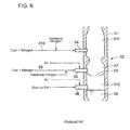
- a coal gasifier 02 comprises a pressure vessel that is provided with a combustor 03 at the inner lower side of the furnace, a reductor burner 04 at the upper side of the combustor 03, and a warm-up burner 06 at the lower side of the combustor burner 03 as well as at the lower side of a slag tap 05.
- the coal (pulverized coal) that is transferred by nitrogen gas (carrier gas) through the fuel supply passage 08 as well as air is thrown into a combustor 07 inside the coal gasifier 02 via the combustor burner; thereby, in the furnace, hot combustion gas is generated mainly by the combustion of the coal. Further, the melting slag is formed, being separated from the hot combustion gas; some part of the slag adheres to the inner wall inside the furnace and drops down along the wall; and some part of the slag directly drops down to the bottom of the furnace. Thus, the generated slag is discharged downward through the slag tap 05.
- cooling water 09 for cooling the discharged slag through the slag tap is stored.
- the coal that is transferred by nitrogen gas (carrier gas) as well as air through the fuel supply passage 010 is thrown into a reductor 011 arranged inside the coal gasifier 02.
- the reductor 011 the coal is mixed with the hot gas, and a coal gasification reaction is performed in a reducing atmosphere so as to yield flammable gas.
- the warm-up burner 06 In starting the operation of the coal gasifier 02, the warm-up burner 06 is used; thereby, auxiliary fuel for warming-up the furnace as well as air or oxygen is supplied to the warm-up burner 06 through which the auxiliary fuel as well as air or oxygen is thrown into a start-up combustion chamber 012 arranged inside the coal gasifier 02.
- the heat produced by the combustion reaction between the auxiliary fuel and air-or-oxygen warms up the inside of the coal gasifier 02; after the temperature inside the furnace 02 exceeds the ignition temperature of the pulverized coal, the pulverized coal together with air is thrown into the combustor 07 via the combustor burner 03; at the same time, the supply of the auxiliary fuel for warm-up is stopped.
- the patent reference 1 JP2002-161283 discloses a method for starting-up the coal gasifier.
- the furnace according to the patent reference 1 comprises:
- the warm-up burner (the start-up burner) 06 of the conventional technology it is needed that a start-up combustion chamber 012 is provided at the lower side of the combustor 07 in the coal gasification (melting) furnace 02, and the warm-up burner 06 is arranged there; thus, the height of the whole coal gasification furnace 02 increases, and the whole system is upsized; further, the number of the stand-pipes that surrounds and configures the pressure vessel 02 also increases; as a result, the manufacturing cost of the furnace increases.
- the tap burner needs to be placed below the slag tap; thus, the height of the coal gasifier is increased, the pressure vessel is upsized, and the manufacturing cost of the furnace is increased.
- the present invention aims at providing a starting method of a coal gasifier and a starting device therefor, whereby pulverized coal is transferred toward the furnace inside by use of an inert transfer gas and the coal thrown into the furnace inside is burnt so that the coal is gasified, wherein a warm-up (start-up) burner can be dispensed with, and a start-up combustion chamber can be accordingly eliminated; a start-up combustion chamber can be down-sized in comparison with the conventional start-up combustion chambers, even when a start-up chamber has to be provided; and, the height of the whole furnace can be restrained.
- the first invention to achieve the above-described objectives is a starting method of a coal gasifier whereby pulverized coal is transferred to the inside of the furnace by use of an inert transfer gas to gasify the coal thrown into the furnace.
- the method comprises the steps of:
- a flammable gas is supplied onto a part way of a fuel supply passage for supplying pulverized coal toward a combustor burner; the flow rate of the flammable gas is reduced, after the temperature of the furnace inside has reached a first temperature at which the pulverized coal can be ignited; then, the supply rates as to the pulverized coal and the transfer gas are increased so that the start-up combustion is shifted to a normal (operation) combustion performed by the pulverized coal and the transfer gas; therefore, the coal gasifier can be started up in a manner that the combustor burner is used also as a warm-up (start-up) burner.
- the warm-up burner can be free from an apprehension that the burner is submerged in the solidified slag derived from the fuel coal; therefore, a stable start-up of the furnace can be achieved.
- the start-up combustion chamber becomes unnecessary; thus, the coal gasifier can be compact (the height can be reduced); further, the numbers of the stand-pipes configuring the pressure vessel can be reduced; as a result, the manufacturing cost of the furnace can be reduced.
- the coal gasifier is directly heated up by the combustor burner that acts as a start-up (warm-up) burner during the start-up operation; thus, the temperature of the furnace inside can be effectively raised, namely, the heating-up performance as to the furnace inside can be enhanced; therefore, the fuel for starting-up the furnace can be saved.
- a preferable mode of the above-described first invention is the starting method of a coal gasifier, the furnace further being provided with an assist warm-up burner placed below the combustor burner and the slag tap.
- the method further comprises the steps of:
- a preferable mode of the above-described second invention is the starting device of a coal gasifier, the furnace further comprising an assist warm-up burner placed below the combustor burner as well as the slag tap; and, the start control means further comprising a start assist burner controller for controlling the start-up operation of the furnace so that the furnace inside is heated up by use of the assist warm-up burner till the temperature of the furnace inside reach a second temperature lower than the first temperature, while the flammable gas is supplied onto (the part way of) the fuel supply passage so as to continue the heat-up after the temperature of the furnace inside has reached the second temperature.
- the assist warm-up burner and the combustor burner perform the warming-up of the furnace during the start-up operation, during the start-up operation of the furnace; thus, in comparison with the conventional way where only a warm-up burner performs the warming-up of the furnace, the time span in which the temperature of the pulverized coal supplied to the furnace inside reaches the first temperature T1 at which the pulverized coal ignites can be reduced. Further, in comparison with the warm-up burner that is used in the conventional furnaces, the assist warm-up burner can be of a small size; thus, the height of the coal gasifier can be reduced. In addition, the upper side and the lower side of the slag tap furnace can be evenly heated up; the slag discharge during the start-up operation, namely during the incipient pulverized coal charging, can be stabilized.
- Another preferable mode of the above-described first invention is the starting method of a coal gasifier, wherein an inert sealing gas is supplied between an outlet of a pulverized coal hopper and a junction point as to the fuel supply passage and a starting gas supply passage when supplying the flammable gas for starting-up the furnace to the fuel supply passage so that back-flow of the starting flammable gas in the passage is prevented by use of the inert sealing gas.
- another preferable mode of the above-described second invention is the starting device of a coal gasifier, the furnace further comprising an inert sealing gas passage for supplying an inert sealing gas between the outlet of the pulverized coal hopper and the coupling point of the starting flammable gas supply passage on the fuel (pulverized coal) supply passage while the sealing flammable gas is supplied onto the pulverized coal supply passage, so that the flammable gas is prevented from flowing back in the fuel (pulverized coal) supply passage toward the hopper, by use of to the inert sealing gas.
- the starting gas (the flammable gas) is prevented from flowing back in the fuel (pulverized coal) supply passage toward the hopper, during the start-up operation of the furnace.
- the flammable gas for the start-up operation can be stably supplied to the furnace during the start-up operation; thus, the start-up of the furnace can be stabilized.
- a starting method of a coal gasifier and a starting device therefor can be provided, whereby pulverized coal is transferred toward the furnace inside by use of an inert transfer gas and the coal thrown into the furnace inside is gasified, wherein a warm-up (start-up) burner can be dispensed with, and a start-up combustion chamber can be accordingly eliminated; a start-up combustion chamber can be down-sized in comparison with the conventional start-up combustion chambers, even when a start-up chamber has to be provided; and, the height of the whole furnace can be restrained.
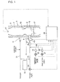
- Fig. 1 shows an outline of a coal gasifier according to the first embodiment of the present invention.
- a pressure vessel 3 forms a coal gasifier 1 that gasifies coal, and comprises a combustor (a combustion furnace) 5 which generates heat and a reductor (a reduction furnace) 7 which performs coal gasification reaction by use of the heat generated in the combustor 5.
- the combustor 5 is provided with at least one combustor burner (a combustion burner) 9 and the reductor 7 is provided with at least one reductor burner 11; in the attached figures, only one combustor burner and only one reductor burner are shown (the other burners are omitted from the figures).
- a partition area (a neck area) 13 is formed between the combustor burner 9 and the reductor burner 11, a partition area (a neck area) 13 is formed; below the combustor burner 9, a slag discharge port, namely slag tap 15, is provided so that the slag drops downward through the slag tap. At the bottom part of the pressure vessel, cooling water 17 for cooling the dropped slag is stored.
- the coal used as fuel that is pulverized into pulverized coal of pertinent particle sizes is transitorily stored in a coal supply hopper (a pulverized coal hopper) 19 (cf. Fig. 5 ).
- Inert nitrogen (carrier gas) is supplied to the outlet of the hopper 19 so as to transfer the coal (the pulverized coal), and the pulverized coal is transferred through a (gas coal) transfer pipe 21 to the reductor burner 11, while additional nitrogen is supplied to the transfer pipe 21.
- the pulverized coal is transferred to the combustor burner 9 through a (coal) fuel supply passage 23. Further, the supply flow rate of the coal transfer nitrogen gas (N 2 A) is adjustable by use of a flow regulating valve 25. In addition, a flow meter 27 is provided at a location P at the combustor inlet side of the (coal) fuel supply passage 23. Based on the information as to the flow rate detected by the flow meter 27 and the other data such as the diameter of the (coal) fuel supply passage and the detected temperature of the inside of the supply passage, the flow velocity of the pulverized coal in the passage to be transferred to the combustor burner 9 is calculated.
- air or oxygen is supplied to the combustor 9,and the air or oxygen is merged with the pulverized coal transferred through the supply passage 23 by the nitrogen (N 2 A), so as to be thrown into the combustor 5 where a combustion gas of a high temperature is generated mainly due to the coal combustion.
- the coal thrown in the reductor 7 is mixed with the high temperature combustion gas generated in the combustor, so that a gasification reaction is performed to generate a flammable gas derived from the coal, under a hot reducing atmosphere.
- a starting gas (a fuel gas) supply passage 29 is connected onto the (coal) fuel supply passage 23; an additional nitrogen (N 2 B) is supplied via a flow meter 31 and a flow regulating valve 33, while a flammable gas (NG1) as a start-up fuel such as natural gas or propane (liquefied petroleum) gas is supplied via a flow meter 35 and a flow regulating valve 37.
- a flammable gas (NG1) as a start-up fuel such as natural gas or propane (liquefied petroleum) gas is supplied via a flow meter 35 and a flow regulating valve 37.
- a detected signal from a furnace inside temperature sensor 41 for detecting the temperature of the furnace inside is inputted together with a signal from the flow meter 27 at the location P on the inlet side of the combustor burner 9, a signal from the flow meter 31 as to the additional nitrogen (N 2 B), and a signal from a flow meter 35 as to the flammable gas (NG1) as the start-up fuel.
- the flow rate adjustments as to the flow rates of the nitrogen (N 2 A), the additional nitrogen (N 2 B), and the start-up fuel (the flammable gas) are performed chiefly by the flow regulating valves 25, 33 and 37 respectively.
- the igniter 43 installed at the tip part of the combustor burner.
- the igniter 43 may use an ignition device of a red heated wire type, plasma generating type and so on.
- the flow regulating valves 37 is opened so that a starting gas (a flammable gas, e.g. NG1) begins to be delivered with a predetermined flow speed.
- a natural gas (NG1) as a start-up fuel is supplied to the (coal) fuel supply passage 23 through the starting gas supply passage 29; then, the natural gas is ignited. After the natural gas is ignited, the activation of the igniter 43 is ceased.
- the start-up gas fuel (NG1) When the start-up gas fuel (NG1) is ignited at a time point t0, the inner temperature of the coal gasifier 1 starts rising as shown in Fig.2 . As the pulverized coal can be ignited when the temperature of the furnace 1 reaches a first temperature T1 at a time point t1, the supply of the start-up gas fuel (NG1) is shifted to the supply of the pulverized coal.
- the openings as to the flow regulating valves 25 and 33 are adjusted so that the flow rates of the carrier gas (N 2 A) and the additional nitrogen (N 2 B) are controlled, and the velocity of the flow in the coal fuel supply passage 23 at the location P is made to be within a predetermined stable transfer flow velocity range H as to the pulverized coal by the aid of the nitrogen (N 2 A, N 2 B) and the start-up fuel (NG1).
- the flow velocity is controlled so as to be within a predetermined stable transfer flow velocity range H.
- the pulverized coal supply is started.
- the openings of the flow regulating valves 25 and 33 are controlled to increase the flow rate of the pulverized coal while the flow regulating valve 37 is controlled to make the flow rate of the start-up fuel (NG1) decreased so that the reduction of the flow rate of the start-up fuel (NG1) is compensated with the increase of the flow rate of the inert nitrogen gas.
- the supply of the start-up fuel (NG1) is stopped at a time point t2 so that the start-up operation is shifted to the normal operation only with the pulverized coal.
- the start-up gas (NG1) is supplied to a part way of the coal fuel supply passage 23 for supplying pulverized coal toward the combustor burner 9; the flow rate of the start-up gas (NG1) is reduced after the temperature inside of the furnace has reached the temperature T1 at which the pulverized coal can be ignited. Then, the supply rates as to the pulverized coal and the transfer gas are increased so that the start-up combustion is shifted to a normal (operation) combustion performed by the pulverized coal and the transfer gas. In this way, the coal gasifier 1 can be started up by making the combustor burner 9 act also as a start-up burner (a warm-up burner) for starting the operation of the furnace.
- start-up burner a warm-up burner
- the warm-up burner can be free from an apprehension that the burner is submerged in the solidified slag derived from the fuel coal Therefore, a stable start-up of the furnace can be achieved.
- the start-up burner (the warm-up burner) besides the combustor burner can be dispensed with, the start-up combustion chamber also becomes unnecessary; thus, the height of the gasifier can be reduced; further, the number of the stand-pipes configuring the pressure vessel 3 of the coal gasifier 1 can be reduced; as a result, the manufacturing cost of the furnace can be reduced.
- the combustor 5 of the coal gasifier 1 is directly heated up by the combustor burner 9 that acts also as a start-up (warm-up) burner during the start-up operation; thus, the temperature of the furnace inside can be effectively raised, namely, the heating-up performance as to the furnace inside can be enhanced; therefore, the fuel for starting-up the furnace can be reduced.
- Fig. 3 shows an outline of a coal gasifier according to the second embodiment of the present invention, whereby Fig.1 corresponds to the first embodiment, while Fig.3 corresponds to the second embodiment.
- an assist warm-up burner (a start assist burner) 50 is provided in the second embodiment in contrast to the first embodiment. Except this difference, the same configuration as that of the first embodiment is followed; thus, the same symbol is used for a same configuration member.
- the assist warm-up burner (a start assist burner) 50 is provided below the combustor burner 9 as well as the slag tap 15; a start control means 52 for controlling the operation of the furnace comprises a start assist burner controller 54 for controlling the start-up operation of the furnace so that the inside of the furnace is heated up by use of the assist warm-up burner 50 till the temperature of the furnace inside reaches a second temperature T2 which is a temperature lower than the first temperature T1.
- the start assist burner controller 54 performs the control as to the supply of the start-up fuel (NG2) so that the start-up fuel (NG2) is supplied to the assist warm-up burner (a start assist burner) 50, through a start assist gas supply passage 56 until the temperature of the furnace inside reaches the second temperature T2.
- the same kind of detected signals as in the first embodiment is inputted.
- a signal from a flow meter 58 as to the start-up fuel (NG2) supplied to the assist warm-up burner (a start assist burner) 50 is inputted to the start control means 52, and the flow rate of the start-up fuel (NG2) is regulated by a flow control valve 60.
- an igniter 62 is fitted to the assist warm-up burner (a start assist burner) 50, as is the case with the combustor burner 9.
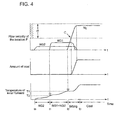
- the start-up fuel (NG2) When the start-up fuel (NG2) is ignited at a time point t0, the temperature in the coal gasifier 1 starts rising as shown in Fig. 4 .
- the temperature of the inside of the furnace reaches the second temperature T2 at a time point t1
- air is supplied to the combustor burner 9 so as to activate the igniter 43 fitted to the tip of the combustor burner 9.
- the flow-regulating valve 37 is opened so as to supply the start-up fuel (NG1) to ignite the natural gas as the fuel (NG1).
- the temperature of the inside of the furnace continues to rise.
- the pulverized coal can be ignited when the temperature of the inside of the furnace reaches the first temperature T1 at a time point t2, the operation by the start-up fuels (NG1 and NG2) is shifted to the operation by the pulverized coal.
- the fuel shift from the start-up fuel (NG1, NG2) into the pulverized coal after the time point t2 is the same as that in the first embodiment.
- the velocity of the flow in the coal fuel supply passage 23 reaches a lower limit C of a predetermined stable transfer flow velocity range H
- the supply of the pulverized coal is started.
- the openings of the flow regulating valves 25 and 33 are controlled to increase the flow rate of the pulverized coal.
- the flow of the natural gas (NG1, NG2) as the start-up fuel is replaced by a flow of inert nitrogen, and the supply of the natural gas is finally stopped at a time point t3 and the furnace operation only with the pulverized coal is continued.
- the start-up of the furnace is performed by the heat-up by means of the assist warm-up burner (a start assist burner) 50 and the combustor burner 9; thus, in comparison with the conventional way where only a warm-up burner performs the warming-up of the furnace, the time span in which the temperature of the pulverized coal supplied to the furnace inside reaches the first temperature T1 at which the pulverized coal ignites can be reduced.
- the assist warm-up burner 50 can be of a small size; thus, the height of the coal gasifier can be reduced.
- the upper side and the lower side of the slag tap furnace can be evenly heated up; the slag discharge during the start-up operation, namely during the incipient pulverized coal charging, can be stabilized.
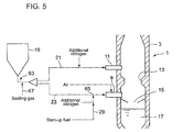
- a sealing gas supply passage 67 for supplying an inert sealing gas toward the (coal) fuel supply passage 23 is provided, the supply passage 67 being connected to a point on the passage 23 between the (coal hopper) outlet 63 of a pulverized coal hopper (funnel) 19 for storing and supplying the pulverized coal and a junction point (a cross point) 65 as to the passage 23 and the starting gas supply passage 29.
- sealing gas supply passage 67 nitrogen gas as a sealing gas is supplied.
- the starting flammable gas for starting-up the operation of the furnace can be prevented from flowing back in the (coal) fuel supply passage 23 toward the pulverized coal hopper (funnel) 19.
- the starting flammable gas can be stably supplied to the coal gasifier during the start-up furnace operation that is described in connection to the above first and second embodiments.
- a starting method of a coal gasifier and a starting device therefor can be provided, whereby pulverized coal is transferred toward the furnace inside by use of an inert transfer gas and the coal thrown into the furnace inside is gasified, wherein a warm-up (start-up) burner can be dispensed with, and a start-up combustion chamber can be accordingly eliminated; a start-up combustion chamber can be down-sized in comparison with the conventional start-up combustion chambers, even when a start-up chamber has to be provided; and, the height of the whole furnace can be restrained.
Landscapes
- Chemical & Material Sciences (AREA)
- Engineering & Computer Science (AREA)
- Combustion & Propulsion (AREA)
- Oil, Petroleum & Natural Gas (AREA)
- Organic Chemistry (AREA)
- Combustion Of Fluid Fuel (AREA)
Abstract
Description
- The present invention relates to a starting method and a device therefor for starting the operation of a coal gasifier in which pulverized coal is charged into the furnace by means of inert transfer-gas (carrier-gas); more in detail, the invention relates to a starting method preferred for starting the operation of the coal gasifier by means of flammable gas, and a device for enforcing the starting method.
- In a coal gasifier of a pressurized two-stage entrained-bed type and an air blowing type furnace which includes a combustor and a reductor; the ash content in the coal as fuel is melted; vitreous slag is formed in the furnace and discharged therefrom; thus, the inner wall of the furnace in operation is covered with the melted slag. Hence, in a case where a starting burner for starting the operation of the furnace is provided at the combustor side of the furnace, the tip part of the starting burner the part which protrudes toward the furnace inside is covered with the slag when the starting burner is stopped and the operation of the furnace is stopped for a long duration of time before the next operation; thus, the restart of the furnace operation becomes difficult; therefore, the starting burner is needed to be, as it used to be, placed at a starting combustion chamber that is provided independently from the combustor.
-
Fig.6 as an example shows a basic configuration as to the starting system for the conventional coal gasifier. As shown inFig. 6 , acoal gasifier 02 comprises a pressure vessel that is provided with acombustor 03 at the inner lower side of the furnace, areductor burner 04 at the upper side of thecombustor 03, and a warm-up burner 06 at the lower side of thecombustor burner 03 as well as at the lower side of aslag tap 05. - The coal (pulverized coal) that is transferred by nitrogen gas (carrier gas) through the
fuel supply passage 08 as well as air is thrown into acombustor 07 inside thecoal gasifier 02 via the combustor burner; thereby, in the furnace, hot combustion gas is generated mainly by the combustion of the coal. Further, the melting slag is formed, being separated from the hot combustion gas; some part of the slag adheres to the inner wall inside the furnace and drops down along the wall; and some part of the slag directly drops down to the bottom of the furnace. Thus, the generated slag is discharged downward through theslag tap 05. - In addition, below the
slag tap 05, coolingwater 09 for cooling the discharged slag through the slag tap is stored. - Also via a
reductor burner 04 that is placed over thecombustor burner 03, the coal (pulverized coal) that is transferred by nitrogen gas (carrier gas) as well as air through thefuel supply passage 010 is thrown into areductor 011 arranged inside thecoal gasifier 02. In thereductor 011, the coal is mixed with the hot gas, and a coal gasification reaction is performed in a reducing atmosphere so as to yield flammable gas. - In starting the operation of the
coal gasifier 02, the warm-up burner 06 is used; thereby, auxiliary fuel for warming-up the furnace as well as air or oxygen is supplied to the warm-up burner 06 through which the auxiliary fuel as well as air or oxygen is thrown into a start-upcombustion chamber 012 arranged inside thecoal gasifier 02. The heat produced by the combustion reaction between the auxiliary fuel and air-or-oxygen warms up the inside of thecoal gasifier 02; after the temperature inside thefurnace 02 exceeds the ignition temperature of the pulverized coal, the pulverized coal together with air is thrown into thecombustor 07 via thecombustor burner 03; at the same time, the supply of the auxiliary fuel for warm-up is stopped. - The subject is now changed into the conventional technology. The patent reference 1 (
JP2002-161283 - As shown in
Fig.7 of this application, the furnace according to thepatent reference 1 comprises: - a coal gasifier (a furnace body) 020;
- a
coal burner 022 and acoal burner 023 that are provided at thecoal gasifier 020, whereby pulverized coal and oxygen are supplied to a furnace-inside 021 in the furnace body via theburners - a
slag tap 024 that is provided at the lower side of thecoal burner 023, whereby the melted slag is discharged via theslag tap 024; - a
tap burner 025 that is provided at the lower side of theslag tap 024, whereby the tap burner heats up theslag tap 024. - In the case of starting the operation of the coal gasifier, before pulverized coal is supplied toward the
coal burners tap burner 025 is burned so as to heat up theslag tap 025 and raise the temperature of the furnace-inside 021. - However, as shown in
Fig.6 , in the warm-up burner (the start-up burner) 06 of the conventional technology, it is needed that a start-up combustion chamber 012 is provided at the lower side of thecombustor 07 in the coal gasification (melting)furnace 02, and the warm-up burner 06 is arranged there; thus, the height of the wholecoal gasification furnace 02 increases, and the whole system is upsized; further, the number of the stand-pipes that surrounds and configures thepressure vessel 02 also increases; as a result, the manufacturing cost of the furnace increases. - In addition, according to the disclosed technology of the patent reference as is the case with the above conventional technology; the tap burner needs to be placed below the slag tap; thus, the height of the coal gasifier is increased, the pressure vessel is upsized, and the manufacturing cost of the furnace is increased.
- In view of the above-described background, the present invention aims at providing a starting method of a coal gasifier and a starting device therefor, whereby pulverized coal is transferred toward the furnace inside by use of an inert transfer gas and the coal thrown into the furnace inside is burnt so that the coal is gasified, wherein a warm-up (start-up) burner can be dispensed with, and a start-up combustion chamber can be accordingly eliminated; a start-up combustion chamber can be down-sized in comparison with the conventional start-up combustion chambers, even when a start-up chamber has to be provided; and, the height of the whole furnace can be restrained.
- The first invention to achieve the above-described objectives is a starting method of a coal gasifier whereby pulverized coal is transferred to the inside of the furnace by use of an inert transfer gas to gasify the coal thrown into the furnace. The method comprises the steps of:
- supplying a flammable gas for starting-up the furnace to a part way of a fuel supply passage for supplying pulverized coal to a combustor burner;
- reducing flow rate of the flammable gas after the temperature of the inside of the furnace reaches a first temperature at which the pulverized coal can be ignited; and
- a starting gas supply passage for supplying a flammable gas for starting-up the furnace to a part way of a fuel supply passage for supplying pulverized coal to a combustor burner;
- a temperature sensing means for sensing the temperature of the inside of the furnace; and
- a start control means for controlling the operation of the furnace,
- According to the first invention as to a starting method as well as the second invention as to a starting device, a flammable gas is supplied onto a part way of a fuel supply passage for supplying pulverized coal toward a combustor burner; the flow rate of the flammable gas is reduced, after the temperature of the furnace inside has reached a first temperature at which the pulverized coal can be ignited; then, the supply rates as to the pulverized coal and the transfer gas are increased so that the start-up combustion is shifted to a normal (operation) combustion performed by the pulverized coal and the transfer gas; therefore, the coal gasifier can be started up in a manner that the combustor burner is used also as a warm-up (start-up) burner.
- In addition, it becomes unnecessary to provide a warm-up burner besides the combustor burner in the combustor; thus, the warm-up burner can be free from an apprehension that the burner is submerged in the solidified slag derived from the fuel coal; therefore, a stable start-up of the furnace can be achieved. Further, since the installation of the warm-up burner (besides the combustor burner) can be dispensed with, the start-up combustion chamber becomes unnecessary; thus, the coal gasifier can be compact (the height can be reduced); further, the numbers of the stand-pipes configuring the pressure vessel can be reduced; as a result, the manufacturing cost of the furnace can be reduced.
- Moreover, the coal gasifier is directly heated up by the combustor burner that acts as a start-up (warm-up) burner during the start-up operation; thus, the temperature of the furnace inside can be effectively raised, namely, the heating-up performance as to the furnace inside can be enhanced; therefore, the fuel for starting-up the furnace can be saved.
- A preferable mode of the above-described first invention is the starting method of a coal gasifier, the furnace further being provided with an assist warm-up burner placed below the combustor burner and the slag tap. The method further comprises the steps of:
- heating the inside of the furnace by use of the assist warm-up burner till the temperature of the inside of the furnace reaches a second temperature which is lower than the first temperature; and
- supplying the flammable gas to the fuel supply passage after the above step of heating-up the inside of the furnace by use of the assist warm-up burner.
- Further, a preferable mode of the above-described second invention is the starting device of a coal gasifier,
the furnace further comprising an assist warm-up burner placed below the combustor burner as well as the slag tap; and,
the start control means further comprising a start assist burner controller for controlling the start-up operation of the furnace so that
the furnace inside is heated up by use of the assist warm-up burner till the temperature of the furnace inside reach a second temperature lower than the first temperature, while the flammable gas is supplied onto (the part way of) the fuel supply passage so as to continue the heat-up after the temperature of the furnace inside has reached the second temperature. - According to the preferable mode of the first invention as to a starting method as well as the preferable mode of the second invention as to a starting device, the assist warm-up burner and the combustor burner perform the warming-up of the furnace during the start-up operation, during the start-up operation of the furnace; thus, in comparison with the conventional way where only a warm-up burner performs the warming-up of the furnace, the time span in which the temperature of the pulverized coal supplied to the furnace inside reaches the first temperature T1 at which the pulverized coal ignites can be reduced. Further, in comparison with the warm-up burner that is used in the conventional furnaces, the assist warm-up burner can be of a small size; thus, the height of the coal gasifier can be reduced. In addition, the upper side and the lower side of the slag tap furnace can be evenly heated up; the slag discharge during the start-up operation, namely during the incipient pulverized coal charging, can be stabilized.
- Another preferable mode of the above-described first invention is the starting method of a coal gasifier, wherein
an inert sealing gas is supplied between an outlet of a pulverized coal hopper and a junction point as to the fuel supply passage and a starting gas supply passage when supplying the flammable gas for starting-up the furnace to the fuel supply passage so that back-flow of the starting flammable gas in the passage is prevented by use of the inert sealing gas. - Further, another preferable mode of the above-described second invention is the starting device of a coal gasifier,
the furnace further comprising an inert sealing gas passage for supplying an inert sealing gas between the outlet of the pulverized coal hopper and the coupling point of the starting flammable gas supply passage on the fuel (pulverized coal) supply passage while the sealing flammable gas is supplied onto the pulverized coal supply passage, so that the flammable gas is prevented from flowing back in the fuel (pulverized coal) supply passage toward the hopper, by use of to the inert sealing gas. - According to the preferable mode of the first invention as to a starting method as well as the preferable mode of the second invention as to a starting device, the starting gas (the flammable gas) is prevented from flowing back in the fuel (pulverized coal) supply passage toward the hopper, during the start-up operation of the furnace. In this way, the flammable gas for the start-up operation can be stably supplied to the furnace during the start-up operation; thus, the start-up of the furnace can be stabilized.
- According to the present invention, a starting method of a coal gasifier and a starting device therefor can be provided, whereby pulverized coal is transferred toward the furnace inside by use of an inert transfer gas and the coal thrown into the furnace inside is gasified, wherein a warm-up (start-up) burner can be dispensed with, and a start-up combustion chamber can be accordingly eliminated; a start-up combustion chamber can be down-sized in comparison with the conventional start-up combustion chambers, even when a start-up chamber has to be provided; and, the height of the whole furnace can be restrained.
-
-
Fig. 1 shows an outline of a coal gasifier according to the first embodiment of the present invention; -
Fig. 2 explains the furnace operation transition during the start-up of the furnace according to the first embodiment; -
Fig. 3 shows an outline of a coal gasifier according to the second embodiment of the present invention, corresponding toFig. 1 ; -
Fig. 4 explains the furnace operation transition during the start-up of the furnace according to the second embodiment, corresponding toFig. 2 ; -
Fig. 5 shows an outline of a coal gasifier according to the third embodiment of the present invention; -
Fig. 6 shows an outline of a coal gasifier according to the conventional technology; -
Fig. 7 shows a whole configuration of a coal gasifier according to the conventional technology. - Hereafter, the present invention will be described in detail with reference to the embodiments shown in the figures. However, the dimensions, materials, shape, the relative placement and so on of a component described in these embodiments shall not be construed as limiting the scope of the invention thereto, unless especially specific mention is made.
- The first embodiment according to the present invention is now explained with reference to
Figs. 1 and2 .Fig. 1 shows an outline of a coal gasifier according to the first embodiment of the present invention. - As shown in
Fig.1 , apressure vessel 3 forms acoal gasifier 1 that gasifies coal, and comprises a combustor (a combustion furnace) 5 which generates heat and a reductor (a reduction furnace) 7 which performs coal gasification reaction by use of the heat generated in thecombustor 5. Thecombustor 5 is provided with at least one combustor burner (a combustion burner) 9 and thereductor 7 is provided with at least onereductor burner 11; in the attached figures, only one combustor burner and only one reductor burner are shown (the other burners are omitted from the figures). - Between the
combustor burner 9 and thereductor burner 11, a partition area (a neck area) 13 is formed; below thecombustor burner 9, a slag discharge port, namelyslag tap 15, is provided so that the slag drops downward through the slag tap. At the bottom part of the pressure vessel, coolingwater 17 for cooling the dropped slag is stored. - The coal used as fuel that is pulverized into pulverized coal of pertinent particle sizes is transitorily stored in a coal supply hopper (a pulverized coal hopper) 19 (cf.
Fig. 5 ). Inert nitrogen (carrier gas) is supplied to the outlet of thehopper 19 so as to transfer the coal (the pulverized coal), and the pulverized coal is transferred through a (gas coal)transfer pipe 21 to thereductor burner 11, while additional nitrogen is supplied to thetransfer pipe 21. - The pulverized coal is transferred to the
combustor burner 9 through a (coal)fuel supply passage 23. Further, the supply flow rate of the coal transfer nitrogen gas (N2A) is adjustable by use of aflow regulating valve 25. In addition, aflow meter 27 is provided at a location P at the combustor inlet side of the (coal)fuel supply passage 23. Based on the information as to the flow rate detected by theflow meter 27 and the other data such as the diameter of the (coal) fuel supply passage and the detected temperature of the inside of the supply passage, the flow velocity of the pulverized coal in the passage to be transferred to thecombustor burner 9 is calculated. - Further, air or oxygen is supplied to the
combustor 9,and the air or oxygen is merged with the pulverized coal transferred through thesupply passage 23 by the nitrogen (N2A), so as to be thrown into thecombustor 5 where a combustion gas of a high temperature is generated mainly due to the coal combustion. The coal thrown in thereductor 7 is mixed with the high temperature combustion gas generated in the combustor, so that a gasification reaction is performed to generate a flammable gas derived from the coal, under a hot reducing atmosphere. - As shown in
Fig.1 , a starting gas (a fuel gas)supply passage 29 is connected onto the (coal)fuel supply passage 23; an additional nitrogen (N2B) is supplied via aflow meter 31 and aflow regulating valve 33, while a flammable gas (NG1) as a start-up fuel such as natural gas or propane (liquefied petroleum) gas is supplied via aflow meter 35 and aflow regulating valve 37. - In the next place, the explanation about the start control means 39 (
Fig.1 ) is given with reference toFig.2 as to the furnace operation transition during the start-up of the furnace. - To the start control means 39, a detected signal from a furnace inside
temperature sensor 41 for detecting the temperature of the furnace inside is inputted together with a signal from theflow meter 27 at the location P on the inlet side of thecombustor burner 9, a signal from theflow meter 31 as to the additional nitrogen (N2B), and a signal from aflow meter 35 as to the flammable gas (NG1) as the start-up fuel. - The flow rate adjustments as to the flow rates of the nitrogen (N2A), the additional nitrogen (N2B), and the start-up fuel (the flammable gas) are performed chiefly by the
flow regulating valves - At first, in starting of the operation of the
coal gasifier 1, air is let into thecombustor burner 9 to activate anigniter 43 installed at the tip part of the combustor burner. Theigniter 43 may use an ignition device of a red heated wire type, plasma generating type and so on. After the igniter is activated, theflow regulating valves 37 is opened so that a starting gas (a flammable gas, e.g. NG1) begins to be delivered with a predetermined flow speed. A natural gas (NG1) as a start-up fuel is supplied to the (coal)fuel supply passage 23 through the startinggas supply passage 29; then, the natural gas is ignited. After the natural gas is ignited, the activation of theigniter 43 is ceased. - When the start-up gas fuel (NG1) is ignited at a time point t0, the inner temperature of the
coal gasifier 1 starts rising as shown inFig.2 . As the pulverized coal can be ignited when the temperature of thefurnace 1 reaches a first temperature T1 at a time point t1, the supply of the start-up gas fuel (NG1) is shifted to the supply of the pulverized coal. - When the temperature inside of the furnace reaches the first temperature T1, the openings as to the
flow regulating valves fuel supply passage 23 at the location P is made to be within a predetermined stable transfer flow velocity range H as to the pulverized coal by the aid of the nitrogen (N2A, N2B) and the start-up fuel (NG1). - In other words, if the pulverized coal transfer becomes unstable in a case where the velocity of the flow in the coal
fuel supply passage 23 fluctuates, then a stable coal-gasification cannot be obtained; thus, the flow velocity is controlled so as to be within a predetermined stable transfer flow velocity range H. - When the flow velocity reaches a lower limit C of the stable transfer flow velocity range H, the pulverized coal supply is started. The openings of the
flow regulating valves flow regulating valve 37 is controlled to make the flow rate of the start-up fuel (NG1) decreased so that the reduction of the flow rate of the start-up fuel (NG1) is compensated with the increase of the flow rate of the inert nitrogen gas. Finally, the supply of the start-up fuel (NG1) is stopped at a time point t2 so that the start-up operation is shifted to the normal operation only with the pulverized coal. - According to the first embodiment as described above, the start-up gas (NG1) is supplied to a part way of the coal
fuel supply passage 23 for supplying pulverized coal toward thecombustor burner 9; the flow rate of the start-up gas (NG1) is reduced after the temperature inside of the furnace has reached the temperature T1 at which the pulverized coal can be ignited. Then, the supply rates as to the pulverized coal and the transfer gas are increased so that the start-up combustion is shifted to a normal (operation) combustion performed by the pulverized coal and the transfer gas. In this way, thecoal gasifier 1 can be started up by making thecombustor burner 9 act also as a start-up burner (a warm-up burner) for starting the operation of the furnace. - Thus, it becomes unnecessary to provide a start-up burner (a warm-up burner) in the combustor for starting the operation of the furnace besides the combustor. Accordingly, the warm-up burner can be free from an apprehension that the burner is submerged in the solidified slag derived from the fuel coal Therefore, a stable start-up of the furnace can be achieved.
- Moreover, thanks to the advantage that the start-up burner (the warm-up burner) besides the combustor burner can be dispensed with, the start-up combustion chamber also becomes unnecessary; thus, the height of the gasifier can be reduced; further, the number of the stand-pipes configuring the
pressure vessel 3 of thecoal gasifier 1 can be reduced; as a result, the manufacturing cost of the furnace can be reduced. - Moreover, the
combustor 5 of thecoal gasifier 1 is directly heated up by thecombustor burner 9 that acts also as a start-up (warm-up) burner during the start-up operation; thus, the temperature of the furnace inside can be effectively raised, namely, the heating-up performance as to the furnace inside can be enhanced; therefore, the fuel for starting-up the furnace can be reduced. - The second embodiment according to the present invention is now explained with reference to
Figs. 3 and4 .Fig. 3 shows an outline of a coal gasifier according to the second embodiment of the present invention, wherebyFig.1 corresponds to the first embodiment, whileFig.3 corresponds to the second embodiment. - The difference between the first and second embodiments is that an assist warm-up burner (a start assist burner) 50 is provided in the second embodiment in contrast to the first embodiment. Except this difference, the same configuration as that of the first embodiment is followed; thus, the same symbol is used for a same configuration member.
- As shown in
Fig. 3 , the assist warm-up burner (a start assist burner) 50 is provided below thecombustor burner 9 as well as theslag tap 15; a start control means 52 for controlling the operation of the furnace comprises a start assistburner controller 54 for controlling the start-up operation of the furnace so that the inside of the furnace is heated up by use of the assist warm-up burner 50 till the temperature of the furnace inside reaches a second temperature T2 which is a temperature lower than the first temperature T1. - The start assist
burner controller 54 performs the control as to the supply of the start-up fuel (NG2) so that the start-up fuel (NG2) is supplied to the assist warm-up burner (a start assist burner) 50, through a start assistgas supply passage 56 until the temperature of the furnace inside reaches the second temperature T2. - The concrete explanation as to the start-up control is now given with reference to
Fig. 4 as to the furnace operation transition during the start-up of the furnace. - To the start control means 52, the same kind of detected signals as in the first embodiment is inputted. In addition to these signals, a signal from a
flow meter 58 as to the start-up fuel (NG2) supplied to the assist warm-up burner (a start assist burner) 50 is inputted to the start control means 52, and the flow rate of the start-up fuel (NG2) is regulated by aflow control valve 60. Further, an igniter 62 is fitted to the assist warm-up burner (a start assist burner) 50, as is the case with thecombustor burner 9. - At first, in starting of the operation of the
coal gasifier 1, air is supplied to the assist warm-up burner (a start assist burner) 50 to activate the igniter 62 fitted to the tip of theburner 50. Then, the flow-regulatingvalve 60 is opened to supply the start-up fuel (NG2) so that a natural gas as the fuel (NG2) is ignited. - When the start-up fuel (NG2) is ignited at a time point t0, the temperature in the
coal gasifier 1 starts rising as shown inFig. 4 . When the temperature of the inside of the furnace reaches the second temperature T2 at a time point t1, air is supplied to thecombustor burner 9 so as to activate theigniter 43 fitted to the tip of thecombustor burner 9. Then, the flow-regulatingvalve 37 is opened so as to supply the start-up fuel (NG1) to ignite the natural gas as the fuel (NG1). - After the start-up fuel (NG1) is ignited at the time point t1, the temperature of the inside of the furnace continues to rise. As the pulverized coal can be ignited when the temperature of the inside of the furnace reaches the first temperature T1 at a time point t2, the operation by the start-up fuels (NG1 and NG2) is shifted to the operation by the pulverized coal.
- The fuel shift from the start-up fuel (NG1, NG2) into the pulverized coal after the time point t2 is the same as that in the first embodiment. When the velocity of the flow in the coal
fuel supply passage 23 reaches a lower limit C of a predetermined stable transfer flow velocity range H, the supply of the pulverized coal is started. Then, the openings of theflow regulating valves - According to the second embodiment as described above, the start-up of the furnace is performed by the heat-up by means of the assist warm-up burner (a start assist burner) 50 and the
combustor burner 9; thus, in comparison with the conventional way where only a warm-up burner performs the warming-up of the furnace, the time span in which the temperature of the pulverized coal supplied to the furnace inside reaches the first temperature T1 at which the pulverized coal ignites can be reduced. Further, in comparison with the warm-up burner that is used in the conventional furnaces, the assist warm-up burner 50 can be of a small size; thus, the height of the coal gasifier can be reduced. Moreover, the upper side and the lower side of the slag tap furnace can be evenly heated up; the slag discharge during the start-up operation, namely during the incipient pulverized coal charging, can be stabilized. - The third embodiment according to the present invention is now explained with reference to
Fig. 5 . - In the method as well as device therefor, according to this third embodiment, a sealing
gas supply passage 67 for supplying an inert sealing gas toward the (coal)fuel supply passage 23 is provided, thesupply passage 67 being connected to a point on thepassage 23 between the (coal hopper)outlet 63 of a pulverized coal hopper (funnel) 19 for storing and supplying the pulverized coal and a junction point (a cross point) 65 as to thepassage 23 and the startinggas supply passage 29. - In the sealing
gas supply passage 67, nitrogen gas as a sealing gas is supplied. - By supplying the sealing gas as described above, the starting flammable gas for starting-up the operation of the furnace can be prevented from flowing back in the (coal)
fuel supply passage 23 toward the pulverized coal hopper (funnel) 19. Thus, the starting flammable gas can be stably supplied to the coal gasifier during the start-up furnace operation that is described in connection to the above first and second embodiments. - According to the present invention, a starting method of a coal gasifier and a starting device therefor can be provided, whereby pulverized coal is transferred toward the furnace inside by use of an inert transfer gas and the coal thrown into the furnace inside is gasified, wherein a warm-up (start-up) burner can be dispensed with, and a start-up combustion chamber can be accordingly eliminated; a start-up combustion chamber can be down-sized in comparison with the conventional start-up combustion chambers, even when a start-up chamber has to be provided; and, the height of the whole furnace can be restrained.
Claims (6)
- A starting method of a coal gasifier whereby pulverized coal is transferred to the inside of the furnace by use of an inert transfer gas to gasify the coal thrown into the furnace, the method comprises the steps of:supplying a flammable gas for starting-up the furnace to a part way of a fuel supply passage for supplying pulverized coal to a combustor burner;reducing flow rate of the flammable gas after the temperature of the inside of the furnace reaches a first temperature at which the pulverized coal can be ignited; andincreasing supply rates of the pulverized coal and the transfer gas in response to the above step of reducing the flow rate of the flammable gas, so that a start-up combustion is shifted to a normal operation combustion performed by the pulverized coal and the transfer gas.
- The starting method of a coal gasifier according to claim 1, the furnace further being provided with an assist warm-up burner placed below the combustor burner and a slag tap, wherein the method further comprises the steps of:heating the inside of the furnace by use of the assist warm-up burner till the temperature of the inside of the furnace reaches a second temperature which is lower than the first temperature; andsupplying the flammable gas to the fuel supply passage after the above step of heating-up the inside of the furnace by use of the assist warm-up burner.
- The starting method of a coal gasifier according to claim 1 or 2, wherein
an inert sealing gas is supplied between an outlet of a pulverized coal hopper and a junction point as to the fuel supply passage and a starting gas supply passage when supplying the flammable gas for starting-up the furnace to the fuel supply passage so that back-flow of the starting flammable gas in the passage is prevented by use of the inert sealing gas. - A starting device of a coal gasifier whereby pulverized coal is transferred to the inside of the furnace by use of an inert transfer gas to gasify the coal thrown into the furnace, the device comprises:a starting gas supply passage for supplying a flammable gas for starting-up the furnace to a part way of a fuel supply passage for supplying pulverized coal to a combustor burner;a temperature sensing means for sensing the temperature of the inside of the furnace; anda start control means for controlling the operation of the furnace,wherein the flow rate of the flammable gas is reduced after the temperature of the inside of the furnace reaches a first temperature at which the pulverized coal can be ignited, while the supply rates of the pulverized coal and the transfer gas are increased in order to shift the start-up combustion to a normal operation combustion performed by the pulverized coal and the transfer gas.
- The starting device of a coal gasifier according to claim 4, wherein the furnace is further provided with an assist warm-up burner placed below the combustor burner and a slag tap; and the start control means comprises
a start assist burner controller for heating up the inside of the furnace to a second temperature which is lower than the first temperature by use of the assist warm-up burner
wherein the flammable gas is supplied to the part way of the fuel supply passage after the temperature of the inside of the furnace reaches the second temperature. - The starting device of a coal gasifier according to claim 4 or 5, wherein
an inert sealing gas is supplied between an outlet of a pulverized coal hopper and a junction point as to the fuel supply passage and a starting gas supply passage when supplying the flammable gas for starting-up the furnace to the fuel supply passage so that back-flow of the starting flammable gas in the passage is prevented by use of the inert sealing gas.
Applications Claiming Priority (2)
| Application Number | Priority Date | Filing Date | Title |
|---|---|---|---|
| JP2008043561A JP5166910B2 (en) | 2008-01-29 | 2008-01-29 | Coal gasifier startup method and starter |
| PCT/JP2008/063090 WO2009096054A1 (en) | 2008-01-29 | 2008-07-15 | Method of starting coal gasification furnace and startup device therefor |
Publications (2)
| Publication Number | Publication Date |
|---|---|
| EP2239312A1 true EP2239312A1 (en) | 2010-10-13 |
| EP2239312A4 EP2239312A4 (en) | 2012-10-31 |
Family
ID=40912419
Family Applications (1)
| Application Number | Title | Priority Date | Filing Date |
|---|---|---|---|
| EP08791377A Withdrawn EP2239312A4 (en) | 2008-01-29 | 2008-07-15 | Method of starting coal gasification furnace and startup device therefor |
Country Status (7)
| Country | Link |
|---|---|
| US (1) | US8414668B2 (en) |
| EP (1) | EP2239312A4 (en) |
| JP (1) | JP5166910B2 (en) |
| CA (1) | CA2695025A1 (en) |
| RU (1) | RU2434932C2 (en) |
| WO (1) | WO2009096054A1 (en) |
| ZA (1) | ZA201000949B (en) |
Cited By (2)
| Publication number | Priority date | Publication date | Assignee | Title |
|---|---|---|---|---|
| CN101838557A (en) * | 2010-02-10 | 2010-09-22 | 马鞍山科达洁能有限公司 | Coal gas producer and coal gas production method |
| CN104479759A (en) * | 2014-12-19 | 2015-04-01 | 刘晓军 | Method for enhancing ignition success rate of gasification furnace start burner |
Families Citing this family (14)
| Publication number | Priority date | Publication date | Assignee | Title |
|---|---|---|---|---|
| DE102008036058B4 (en) * | 2008-08-01 | 2013-04-18 | Linde Ag | Method and device for starting up combustible gasification reactors |
| JP5678606B2 (en) * | 2010-11-25 | 2015-03-04 | 株式会社Ihi | Boiler equipment |
| JP5654338B2 (en) * | 2010-12-20 | 2015-01-14 | 日本エア・リキード株式会社 | Nitrogen gas production apparatus and gasification combined power generation system using the same |
| JP5615199B2 (en) * | 2011-02-21 | 2014-10-29 | 三菱重工業株式会社 | Combustion device |
| US20120255301A1 (en) * | 2011-04-06 | 2012-10-11 | Bell Peter S | System for generating power from a syngas fermentation process |
| US8945507B2 (en) * | 2011-04-21 | 2015-02-03 | Kellogg Brown & Root Llc | Systems and methods for operating a gasifier |
| US8673181B2 (en) * | 2011-08-11 | 2014-03-18 | Kellogg Brown & Root Llc | Systems and methods for starting up a gasifier |
| TR201819990T4 (en) | 2014-06-27 | 2019-01-21 | Tuerkiye Bilimsel Ve Teknolojik Arastirma Kurumu Tuebitak | A COAL FEEDING SYSTEM. |
| CN105132023B (en) * | 2015-08-26 | 2018-06-19 | 上海泽玛克敏达机械设备有限公司 | Block powder integration gasification furnace and the method for block powder integration gasification |
| JP6637797B2 (en) * | 2016-03-11 | 2020-01-29 | 三菱日立パワーシステムズ株式会社 | Carbon-containing raw material gasification system and method for setting oxidizing agent distribution ratio |
| BR112019014015A2 (en) * | 2017-01-06 | 2020-02-11 | Fenix Advanced Technologies, Limited | GAS SUSPENSION TRANSPORTABLE FUEL OF SOLID FUEL PARTICLES |
| CN113341703B (en) * | 2021-05-11 | 2022-11-15 | 中国大唐集团科学技术研究院有限公司西北电力试验研究院 | Pre-coaling feed-forward optimal time difference method for grinding starting pre-judgment |
| WO2023164079A1 (en) * | 2022-02-25 | 2023-08-31 | Sierra Energy | Fixed bed gasifier |
| CN114644946B (en) * | 2022-03-01 | 2022-11-29 | 徐州乔氏机械设备有限公司 | Intelligent coal gas making device |
Family Cites Families (13)
| Publication number | Priority date | Publication date | Assignee | Title |
|---|---|---|---|---|
| US4490156A (en) * | 1981-06-10 | 1984-12-25 | Texaco Inc. | Partial oxidation system |
| GB2099843B (en) | 1981-06-10 | 1985-01-30 | Texaco Development Corp | Partial oxidation process |
| JPS58154797A (en) * | 1982-03-10 | 1983-09-14 | Babcock Hitachi Kk | Starting spouted-bed coal gasifier |
| JPH083104B2 (en) * | 1986-11-27 | 1996-01-17 | バブコツク日立株式会社 | Burner device for coal gasifier |
| GB2202234B (en) | 1987-03-16 | 1991-09-18 | Shell Int Research | Method for starting up a partial combustion process |
| RU2009402C1 (en) | 1991-03-04 | 1994-03-15 | Варанкин Геннадий Юрьевич | Method and device for burning low-reaction powdered fuel |
| JP3492099B2 (en) | 1995-10-03 | 2004-02-03 | 三菱重工業株式会社 | Burner |
| US6033447A (en) * | 1997-06-25 | 2000-03-07 | Eastman Chemical Company | Start-up process for a gasification reactor |
| JPH11279568A (en) | 1998-03-26 | 1999-10-12 | Nippon Steel Corp | Char feeder of coal gasification system |
| JP4070325B2 (en) | 1998-10-16 | 2008-04-02 | 三菱重工業株式会社 | Pulverized coal supply system for coal gasifier |
| EP1349907A4 (en) * | 2000-11-17 | 2006-03-08 | Jaw Entpr Llc | Small scale high throughput biomass gasification system and method |
| JP2002161283A (en) * | 2000-11-27 | 2002-06-04 | Babcock Hitachi Kk | Startup method for coal gasifier |
| RU49186U1 (en) | 2005-07-08 | 2005-11-10 | Общество с ограниченной ответственностью Научно производственная компания "АДАПТИКА" | WASTE BURNING PLANT |
-
2008
- 2008-01-29 JP JP2008043561A patent/JP5166910B2/en not_active Expired - Fee Related
- 2008-07-15 RU RU2010105050/05A patent/RU2434932C2/en not_active IP Right Cessation
- 2008-07-15 WO PCT/JP2008/063090 patent/WO2009096054A1/en not_active Ceased
- 2008-07-15 EP EP08791377A patent/EP2239312A4/en not_active Withdrawn
- 2008-07-15 CA CA2695025A patent/CA2695025A1/en not_active Abandoned
- 2008-07-15 US US12/452,854 patent/US8414668B2/en not_active Expired - Fee Related
-
2010
- 2010-02-09 ZA ZA2010/00949A patent/ZA201000949B/en unknown
Cited By (4)
| Publication number | Priority date | Publication date | Assignee | Title |
|---|---|---|---|---|
| CN101838557A (en) * | 2010-02-10 | 2010-09-22 | 马鞍山科达洁能有限公司 | Coal gas producer and coal gas production method |
| CN101838557B (en) * | 2010-02-10 | 2011-09-21 | 马鞍山科达洁能股份有限公司 | Coal gas producer and coal gas production method |
| CN104479759A (en) * | 2014-12-19 | 2015-04-01 | 刘晓军 | Method for enhancing ignition success rate of gasification furnace start burner |
| CN104479759B (en) * | 2014-12-19 | 2016-09-07 | 刘晓军 | A kind of method improving gasifier to start working burner ignition success rate |
Also Published As
| Publication number | Publication date |
|---|---|
| JP5166910B2 (en) | 2013-03-21 |
| CA2695025A1 (en) | 2009-08-06 |
| RU2010105050A (en) | 2011-08-20 |
| US20100180503A1 (en) | 2010-07-22 |
| JP2009179790A (en) | 2009-08-13 |
| EP2239312A4 (en) | 2012-10-31 |
| ZA201000949B (en) | 2011-04-28 |
| RU2434932C2 (en) | 2011-11-27 |
| US8414668B2 (en) | 2013-04-09 |
| WO2009096054A1 (en) | 2009-08-06 |
Similar Documents
| Publication | Publication Date | Title |
|---|---|---|
| US8414668B2 (en) | Starting method of coal gasifier and starting device therefor | |
| US6199366B1 (en) | Gas turbine | |
| RU2670506C2 (en) | Start-up torch | |
| US5445087A (en) | Apparatus for incinerating waste material | |
| CN114174721A (en) | Ammonia combustion method and ammonia combustion system | |
| EP3313791B1 (en) | Submerged combustion glass melter with oxygen/gas heat-up burner system | |
| AU2009275490B2 (en) | Method and apparatus for starting up gasifying reactors operated with combustible dust | |
| EP4001763B1 (en) | Torch igniter system | |
| JP5216076B2 (en) | Melting furnace using slag melting oxygen burner | |
| CN103486577A (en) | Natural gas ignition system for circulating fluidized bed boiler | |
| US8726630B2 (en) | System and method for passive valving for pulse detonation combustors | |
| JP2527922B2 (en) | Pulverized coal oxygen combustion burner | |
| JP3924224B2 (en) | Gasifier and burner | |
| JP5517886B2 (en) | Ignition torch and pressurized gasifier | |
| RU2667280C1 (en) | Device for generating the heat and hydrogen | |
| JP6228788B2 (en) | Coal gasifier | |
| RU2839358C1 (en) | Reactor for production of synthesis gas | |
| EP4163251A1 (en) | Reactor for partial oxidation of hydrocarbons | |
| RU2842893C1 (en) | Ignition device | |
| JP4285760B2 (en) | Operation control method of gasification and melting system and system | |
| JP2020159584A (en) | Method for starting circulation fluidized bed boiler | |
| JPH08302365A (en) | Gasification apparatus for coal or the like | |
| US20180372312A1 (en) | Biomass auto combustion chamber | |
| KR850000950B1 (en) | Control method for a heater with fluidised bed | |
| CN118146837A (en) | A water-coal slurry gasification system and feeding control method |
Legal Events
| Date | Code | Title | Description |
|---|---|---|---|
| PUAI | Public reference made under article 153(3) epc to a published international application that has entered the european phase |
Free format text: ORIGINAL CODE: 0009012 |
|
| 17P | Request for examination filed |
Effective date: 20100212 |
|
| AK | Designated contracting states |
Kind code of ref document: A1 Designated state(s): AT BE BG CH CY CZ DE DK EE ES FI FR GB GR HR HU IE IS IT LI LT LU LV MC MT NL NO PL PT RO SE SI SK TR |
|
| AX | Request for extension of the european patent |
Extension state: AL BA MK RS |
|
| DAX | Request for extension of the european patent (deleted) | ||
| RIC1 | Information provided on ipc code assigned before grant |
Ipc: C10J 3/46 20060101AFI20120920BHEP Ipc: C10B 53/04 20060101ALI20120920BHEP Ipc: C10J 3/72 20060101ALI20120920BHEP |
|
| A4 | Supplementary search report drawn up and despatched |
Effective date: 20121004 |
|
| RIC1 | Information provided on ipc code assigned before grant |
Ipc: C10B 53/04 20060101ALI20120927BHEP Ipc: C10J 3/72 20060101ALI20120927BHEP Ipc: C10J 3/46 20060101AFI20120927BHEP |
|
| 17Q | First examination report despatched |
Effective date: 20130610 |
|
| STAA | Information on the status of an ep patent application or granted ep patent |
Free format text: STATUS: THE APPLICATION HAS BEEN WITHDRAWN |
|
| 18W | Application withdrawn |
Effective date: 20140528 |