EP2239090A1 - Vertical turret lathe with automatic tool exchanger - Google Patents
Vertical turret lathe with automatic tool exchanger Download PDFInfo
- Publication number
- EP2239090A1 EP2239090A1 EP10405068A EP10405068A EP2239090A1 EP 2239090 A1 EP2239090 A1 EP 2239090A1 EP 10405068 A EP10405068 A EP 10405068A EP 10405068 A EP10405068 A EP 10405068A EP 2239090 A1 EP2239090 A1 EP 2239090A1
- Authority
- EP
- European Patent Office
- Prior art keywords
- tool
- turret
- automatic
- automatic tool
- tool changer
- Prior art date
- Legal status (The legal status is an assumption and is not a legal conclusion. Google has not performed a legal analysis and makes no representation as to the accuracy of the status listed.)
- Granted
Links
Images






Classifications
-
- B—PERFORMING OPERATIONS; TRANSPORTING
- B23—MACHINE TOOLS; METAL-WORKING NOT OTHERWISE PROVIDED FOR
- B23Q—DETAILS, COMPONENTS, OR ACCESSORIES FOR MACHINE TOOLS, e.g. ARRANGEMENTS FOR COPYING OR CONTROLLING; MACHINE TOOLS IN GENERAL CHARACTERISED BY THE CONSTRUCTION OF PARTICULAR DETAILS OR COMPONENTS; COMBINATIONS OR ASSOCIATIONS OF METAL-WORKING MACHINES, NOT DIRECTED TO A PARTICULAR RESULT
- B23Q3/00—Devices holding, supporting, or positioning work or tools, of a kind normally removable from the machine
- B23Q3/155—Arrangements for automatic insertion or removal of tools, e.g. combined with manual handling
- B23Q3/15506—Arrangements for automatic insertion or removal of tools, e.g. combined with manual handling the tool being inserted in a tool holder directly from a storage device (without transfer device)
-
- B—PERFORMING OPERATIONS; TRANSPORTING
- B23—MACHINE TOOLS; METAL-WORKING NOT OTHERWISE PROVIDED FOR
- B23B—TURNING; BORING
- B23B29/00—Holders for non-rotary cutting tools; Boring bars or boring heads; Accessories for tool holders
- B23B29/24—Tool holders for a plurality of cutting tools, e.g. turrets
-
- B—PERFORMING OPERATIONS; TRANSPORTING
- B23—MACHINE TOOLS; METAL-WORKING NOT OTHERWISE PROVIDED FOR
- B23B—TURNING; BORING
- B23B3/00—General-purpose turning-machines or devices, e.g. centre lathes with feed rod and lead screw; Sets of turning-machines
- B23B3/08—Turning-machines characterised by the use of faceplates
- B23B3/10—Turning-machines characterised by the use of faceplates with the faceplate horizontal, i.e. vertical boring and turning machines
-
- B—PERFORMING OPERATIONS; TRANSPORTING
- B23—MACHINE TOOLS; METAL-WORKING NOT OTHERWISE PROVIDED FOR
- B23Q—DETAILS, COMPONENTS, OR ACCESSORIES FOR MACHINE TOOLS, e.g. ARRANGEMENTS FOR COPYING OR CONTROLLING; MACHINE TOOLS IN GENERAL CHARACTERISED BY THE CONSTRUCTION OF PARTICULAR DETAILS OR COMPONENTS; COMBINATIONS OR ASSOCIATIONS OF METAL-WORKING MACHINES, NOT DIRECTED TO A PARTICULAR RESULT
- B23Q3/00—Devices holding, supporting, or positioning work or tools, of a kind normally removable from the machine
- B23Q3/155—Arrangements for automatic insertion or removal of tools, e.g. combined with manual handling
- B23Q2003/15586—Arrangements for automatic insertion or removal of tools, e.g. combined with manual handling of tools in turrets
-
- Y—GENERAL TAGGING OF NEW TECHNOLOGICAL DEVELOPMENTS; GENERAL TAGGING OF CROSS-SECTIONAL TECHNOLOGIES SPANNING OVER SEVERAL SECTIONS OF THE IPC; TECHNICAL SUBJECTS COVERED BY FORMER USPC CROSS-REFERENCE ART COLLECTIONS [XRACs] AND DIGESTS
- Y10—TECHNICAL SUBJECTS COVERED BY FORMER USPC
- Y10T—TECHNICAL SUBJECTS COVERED BY FORMER US CLASSIFICATION
- Y10T483/00—Tool changing
- Y10T483/17—Tool changing including machine tool or component
- Y10T483/1702—Rotating work machine tool [e.g., screw machine, lathe, etc.]
-
- Y—GENERAL TAGGING OF NEW TECHNOLOGICAL DEVELOPMENTS; GENERAL TAGGING OF CROSS-SECTIONAL TECHNOLOGIES SPANNING OVER SEVERAL SECTIONS OF THE IPC; TECHNICAL SUBJECTS COVERED BY FORMER USPC CROSS-REFERENCE ART COLLECTIONS [XRACs] AND DIGESTS
- Y10—TECHNICAL SUBJECTS COVERED BY FORMER USPC
- Y10T—TECHNICAL SUBJECTS COVERED BY FORMER US CLASSIFICATION
- Y10T483/00—Tool changing
- Y10T483/17—Tool changing including machine tool or component
- Y10T483/1702—Rotating work machine tool [e.g., screw machine, lathe, etc.]
- Y10T483/1707—Tool having specific mounting or work treating feature
-
- Y—GENERAL TAGGING OF NEW TECHNOLOGICAL DEVELOPMENTS; GENERAL TAGGING OF CROSS-SECTIONAL TECHNOLOGIES SPANNING OVER SEVERAL SECTIONS OF THE IPC; TECHNICAL SUBJECTS COVERED BY FORMER USPC CROSS-REFERENCE ART COLLECTIONS [XRACs] AND DIGESTS
- Y10—TECHNICAL SUBJECTS COVERED BY FORMER USPC
- Y10T—TECHNICAL SUBJECTS COVERED BY FORMER US CLASSIFICATION
- Y10T483/00—Tool changing
- Y10T483/17—Tool changing including machine tool or component
- Y10T483/1702—Rotating work machine tool [e.g., screw machine, lathe, etc.]
- Y10T483/1714—Tool changer between tool support and matrix
- Y10T483/1719—Tool support comprises turret
-
- Y—GENERAL TAGGING OF NEW TECHNOLOGICAL DEVELOPMENTS; GENERAL TAGGING OF CROSS-SECTIONAL TECHNOLOGIES SPANNING OVER SEVERAL SECTIONS OF THE IPC; TECHNICAL SUBJECTS COVERED BY FORMER USPC CROSS-REFERENCE ART COLLECTIONS [XRACs] AND DIGESTS
- Y10—TECHNICAL SUBJECTS COVERED BY FORMER USPC
- Y10T—TECHNICAL SUBJECTS COVERED BY FORMER US CLASSIFICATION
- Y10T483/00—Tool changing
- Y10T483/17—Tool changing including machine tool or component
- Y10T483/1702—Rotating work machine tool [e.g., screw machine, lathe, etc.]
- Y10T483/1714—Tool changer between tool support and matrix
- Y10T483/1719—Tool support comprises turret
- Y10T483/1721—Linearly moveable tool changer
-
- Y—GENERAL TAGGING OF NEW TECHNOLOGICAL DEVELOPMENTS; GENERAL TAGGING OF CROSS-SECTIONAL TECHNOLOGIES SPANNING OVER SEVERAL SECTIONS OF THE IPC; TECHNICAL SUBJECTS COVERED BY FORMER USPC CROSS-REFERENCE ART COLLECTIONS [XRACs] AND DIGESTS
- Y10—TECHNICAL SUBJECTS COVERED BY FORMER USPC
- Y10T—TECHNICAL SUBJECTS COVERED BY FORMER US CLASSIFICATION
- Y10T483/00—Tool changing
- Y10T483/17—Tool changing including machine tool or component
- Y10T483/1702—Rotating work machine tool [e.g., screw machine, lathe, etc.]
- Y10T483/1726—Direct tool exchange between tool support and matrix
-
- Y—GENERAL TAGGING OF NEW TECHNOLOGICAL DEVELOPMENTS; GENERAL TAGGING OF CROSS-SECTIONAL TECHNOLOGIES SPANNING OVER SEVERAL SECTIONS OF THE IPC; TECHNICAL SUBJECTS COVERED BY FORMER USPC CROSS-REFERENCE ART COLLECTIONS [XRACs] AND DIGESTS
- Y10—TECHNICAL SUBJECTS COVERED BY FORMER USPC
- Y10T—TECHNICAL SUBJECTS COVERED BY FORMER US CLASSIFICATION
- Y10T82/00—Turning
- Y10T82/25—Lathe
- Y10T82/2508—Lathe with tool turret
-
- Y—GENERAL TAGGING OF NEW TECHNOLOGICAL DEVELOPMENTS; GENERAL TAGGING OF CROSS-SECTIONAL TECHNOLOGIES SPANNING OVER SEVERAL SECTIONS OF THE IPC; TECHNICAL SUBJECTS COVERED BY FORMER USPC CROSS-REFERENCE ART COLLECTIONS [XRACs] AND DIGESTS
- Y10—TECHNICAL SUBJECTS COVERED BY FORMER USPC
- Y10T—TECHNICAL SUBJECTS COVERED BY FORMER US CLASSIFICATION
- Y10T82/00—Turning
- Y10T82/25—Lathe
- Y10T82/2511—Vertical
-
- Y—GENERAL TAGGING OF NEW TECHNOLOGICAL DEVELOPMENTS; GENERAL TAGGING OF CROSS-SECTIONAL TECHNOLOGIES SPANNING OVER SEVERAL SECTIONS OF THE IPC; TECHNICAL SUBJECTS COVERED BY FORMER USPC CROSS-REFERENCE ART COLLECTIONS [XRACs] AND DIGESTS
- Y10—TECHNICAL SUBJECTS COVERED BY FORMER USPC
- Y10T—TECHNICAL SUBJECTS COVERED BY FORMER US CLASSIFICATION
- Y10T82/00—Turning
- Y10T82/25—Lathe
- Y10T82/2585—Tool rest
- Y10T82/2587—Turret type holder [e.g., multiple tools, etc.]
Definitions
- the vertical turret lathe further comprises a door for the automatic tool changer unit to enter the machining area.
- the outer diameter turning tool T 1 performs machining of the outer diameter portion of a workpiece W 1 held on a work table 20.
- the inner diameter turning tool T 2 performs machining of the inner diameter portion of the workpiece W 1 , and the protrusion length of the inner diameter turning tool T 2 is long. This causes a drawback in that the inner diameter turning tool T 2 interferes with the workpiece W 1 during machining of the outer diameter portion.
- the tool holder unit 80 has a shank hole 82 formed within the housing corresponding to a tool shank, and a click 84 capable of moving in the axial direction disposed in the shank hole 82.
- the click 84 interlocks with a piston 86, and a pair of hydraulic ports P 1 and P 2 is located at either side of the piston 86.
- the pins 74 and 76 are alternately pushed in, by which the hydraulic oil filled therein is supplied to port P 1 or port P 2 via a circuit not shown so as to clamp or unclamp the tool shank.
- step S8 the magazine 120 is turned.
- step S10 the clamping piston 162 is projected so as to clamp a tool T 21 .
- step S13 the ATC door 55 is closed.
- step S14 the turret tool rest 50 is allocated.
- step S15 the turret tool rest 50 is moved to the machining position.
- the automatic tool change of the tool is completed. Further, during machining of the outer diameter of the work, the tool on the tool holder 70 is removed so as to prevent the tools from interfering with the workpiece without fail.
Landscapes
- Engineering & Computer Science (AREA)
- Mechanical Engineering (AREA)
- Automatic Tool Replacement In Machine Tools (AREA)
Abstract
Description
- The present invention relates to a vertical turret lathe, and more specifically, to a vertical turret lathe equipped with an automatic tool changer apparatus.
- A turret lathe has twelve turning tool mounting portions formed on the circumference of a turret tool rest, for example, and is capable of realizing efficient machining in a short time by selecting appropriate tools.
- Japanese patent application laid-open publication No.
2008-80416 - However, according to the disclosure of
patent document 1, hydraulic pressure is supplied to a tool holder positioned at an automatic tool changing position using a hydraulic oil supplying means capable of being attached and removed via a socket. - According to the disclosed arrangement, defects are caused by the leakage of hydraulic oil from the circuit, the foreign substances coming into the circuit, and so on.
- The present invention aims at solving the problems of the prior art by providing an automatic tool changer apparatus of a vertical turret lathe capable of automatically changing the tools on a turret tool rest using a tool holder having mechanically operated pins, without having to apply hydraulic pressure from the exterior.
- The vertical turret lathe according to the present invention comprises, as basic means, a work table holding a workpiece and rotating, a working head moving in X-axis and Z-axis directions, and a turret tool rest disposed on the working head within a machining area, the vertical turret lathe comprising a tool holder disposed on a tool attachment portion on the turret tool rest, and an automatic tool changer apparatus disposed outside the machining area for automatically changing the tools on the tool holder, wherein the tool holder comprises a pair of mechanically operated pins, and a means for clamping or unclamping the tool via hydraulic pressure in response to the operation of the pins, wherein the automatic tool changer apparatus comprises a tool magazine facing the tool holder for changing the tools, and a pair of cylinders for operating the pins on the tool holder.
- Further, the automatic tool changer apparatus comprises a frame, a slide rail disposed on the frame, and an automatic tool changer unit moving on the slide rail and changing tools within the machining area, wherein the automatic tool changer unit comprises a turret-type tool magazine, and the turret-type tool magazine comprises a gripper for gripping the tool, and a spring for biasing the gripper towards the closing direction.
- Moreover, the vertical turret lathe further comprises a door for the automatic tool changer unit to enter the machining area.
- According to the present invention, a long-sized inner diameter turning tool or the like can be attached to the tool holder in a changeable manner, so that during machining of the outer diameter of a workpiece, the inner diameter turning tool can be prevented from interfering with the workpiece, and the processing of various types of workpieces can be performed without performing tooling changes.
-
-
FIG. 1 is an external view of a vertical turret lathe according to the present invention; -
FIG. 2 is an explanatory view showing the mechanical structure of a relevant portion thereof; -
FIG. 3 is an explanatory view showing an outline of a common turret lathe; -
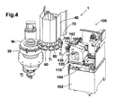
FIG. 4 is an explanatory view showing the structure of a turret tool rest and an automatic tool changer apparatus; -
FIG. 5 is an explanatory view showing the structure of a turret tool rest and an automatic tool changer apparatus; -
FIG. 6 is an external view of a tool holder; -
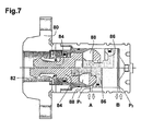
FIG. 7 is a cross-sectional view of a tool holder unit; -
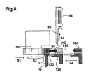
FIG. 8 is an explanatory view showing the operation of the automatic tool changer apparatus according to the present invention; -
FIG. 9 is an explanatory view showing the operation of the automatic tool changer apparatus according to the present invention; -
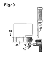
FIG. 10 is an explanatory view showing the operation of the automatic tool changer apparatus according to the present invention; -
FIG. 11 is an explanatory view showing the operation of the automatic tool changer apparatus according to the present invention; and -
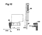
FIG. 12 is an explanatory view showing the operation of the automatic tool changer apparatus according to the present invention. -
FIG. 1 is an external view of a vertical turret lathe for realizing the present invention, andFIG. 2 is an explanatory view showing the mechanical structure of the relevant portion thereof. - The vertical turret lathe denoted as a whole by
reference number 1 has a work area WA provided on abase 10, and a work table 20 that grips a workpiece and rotates. - A
column 30 that moves along an X axis is provided on thebase 10, and on thecolumn 30 is disposed a workinghead 40 that moves along a Z axis parallel to a rotation axis of the work table 20. Aturret tool rest 50 is rotatably disposed on the workinghead 40 in an allocatable manner. -
FIG. 3 is an explanatory view showing the outline of a common turret lathe. - The
turret tool rest 50 has, for example, a dodecagon shape, and includes twelvetool supporting portions 60. Outer diameter turning tools T1 and inner diameter turning tools T2 are disposed on the respectivetool supporting portions 60. - The outer diameter turning tool T1 performs machining of the outer diameter portion of a workpiece W1 held on a work table 20. The inner diameter turning tool T2 performs machining of the inner diameter portion of the workpiece W1, and the protrusion length of the inner diameter turning tool T2 is long. This causes a drawback in that the inner diameter turning tool T2 interferes with the workpiece W1 during machining of the outer diameter portion.
- Therefore, to cope with this problem in a realistic manner, the occurrence of interference is prevented by attaching the inner diameter turning tool on a tool holder at a distant position and not attaching the inner diameter turning tool on the adjacent tool holders. This method, however, limits the number of tools to be attached to the
turret tool rest 50 and causes deterioration of machining efficiency. - The vertical turret lathe according to the present invention improves the machining efficiency thereof by attaching an automatic tool changer apparatus to either temporarily remove the inner diameter turning tool from the turret tool rest or change the tool to an inner diameter turning tool most suitable for machining.
- As shown in
FIG. 2 , an automatictool changer apparatus 100 is arranged adjacent to the work area WA, and adoor 55 closes and separates the automatictool changer apparatus 100 from the work area WA having the work table 20 and the turret tool rest 50 during machining. -
FIGS. 4 and5 are explanatory views showing the structure of theturret tool rest 50 and the automatictool changer apparatus 100. - A
tool holder 70 described later is disposed on thetool supporting portion 60 of theturret tool rest 50, and an automatictool changer apparatus 100 is disposed to face to thetool holder 70. - The automatic
tool changer apparatus 100 has aguide rail 104 disposed on aframe 102, and an automatictool changer unit 110 is disposed movably on therail 104. - The automatic
tool changer unit 110 has a turret-type tool magazine 120. Thetool magazine 120 has a pair ofgrippers 130 and aspring 140 that biases thegripper 130 toward the closing direction. - The inner diameter turning tool T2 held via the
gripper 130 can be drawn out resisting against the force of thespring 140 by applying force toward the outer direction, and the tool can also be pushed into the gripper. - The
tool holder 70 has a pair ofpins pins - The automatic
tool changer unit 110 has acylinder 150, and the twopistons pins tool holder 70. -
FIG. 6 is an explanatory view showing the external view of thetool holder 70, andFIG. 7 is a cross-sectional view showing the structure of thetool holder unit 80 disposed within thetool holder 70. - The
tool holder unit 80 has ashank hole 82 formed within the housing corresponding to a tool shank, and aclick 84 capable of moving in the axial direction disposed in theshank hole 82. The click 84 interlocks with apiston 86, and a pair of hydraulic ports P1 and P2 is located at either side of thepiston 86. - By supplying hydraulic oil to the first port P1, the
click 84 slides back together with thepiston 86, and clamps the shank of the tool inserted to theshank hole 82. Once the clamped state is realized, the clamp is self-locked via thepiston 86 and awedge member 88. By supplying hydraulic oil to the second port P2, thepiston 86 and theclick 84 are moved forward and the shank of the tool is unclamped. - According to the
tool holder 70 used in the present invention, thepins - The operation of the automatic tool changer apparatus according to the present invention will be described with reference to
FIGS. 8 through 12 . - In step S1, the
turret tool rest 50 is moved to the original point of ATC (automatic tool change). - In step S2, the
turret tool rest 50 is allocated. - In step S3, the ATC
door 55 is opened. - In step S4, the
magazine 120 of the automatic tool changer apparatus is advanced, and the tool T2 is received via thegripper 130. - In step S5, the
unclamping piston 160 is projected so as to unclamp the tool on thetool holder 70. - In step S6, the
unclamping piston 160 is pulled back. - In step S7, the
turret tool rest 50 is moved in the +Z direction. - In step S8, the
magazine 120 is turned. - In step S9, the
turret tool rest 50 is moved to the original point of ATC. - In step S10, the
clamping piston 162 is projected so as to clamp a tool T21. - In step S11, the
clamping piston 162 is pulled back. - In step S12, the
magazine 120 is pulled back. - In step S13, the
ATC door 55 is closed. - In step S14, the
turret tool rest 50 is allocated. - In step S15, the
turret tool rest 50 is moved to the machining position. - By the above-mentioned operation, the automatic tool change of the tool is completed. Further, during machining of the outer diameter of the work, the tool on the
tool holder 70 is removed so as to prevent the tools from interfering with the workpiece without fail.
Claims (5)
- A vertical turret lathe having a work table holding a workpiece and rotating, a working head moving in X-axis and Z-axis directions, and a turret tool rest disposed on the working head within a machining area, the vertical turret lathe comprising:a tool holder disposed on a tool attachment portion on the turret tool rest, and an automatic tool changer apparatus disposed outside the machining area for automatically changing the tools on the tool holder, wherein the tool holder comprises a pair of mechanically operated pins, and a means for clamping or unclamping the tool via hydraulic pressure in response to the operation of the pins, wherein the automatic tool changer apparatus comprises a tool magazine facing the tool holder for changing the tools, and a pair of cylinders for operating the pins on the tool holder.
- The vertical turret lathe according to claim 1, wherein
the automatic tool changer apparatus comprises a frame, a slide rail disposed on the frame and an automatic tool changer unit moving on the slide rail and changing tools within the machining area, and the automatic tool changer unit comprises a turret-type tool magazine. - The vertical turret lathe according to claim 1, wherein
the automatic tool changer apparatus comprises a frame, a slide rail disposed on the frame and an automatic tool changer unit moving on the slide rail and changing tools within the machining area, the automatic tool changer unit comprising a turret-type tool magazine, and the turret-type tool magazine comprising a gripper for gripping the tool and a spring for biasing the gripper towards the closing direction. - The vertical turret lathe according to claim 1, wherein
the automatic tool changer apparatus comprises a frame, a slide rail disposed on the frame and an automatic tool changer unit moving on the slide rail and changing tools within the machining area, and the vertical turret lathe comprises a door for the automatic tool changer unit to enter the machining area. - The vertical turret lathe according to claim 1, wherein
the tool attached to the tool holder is an inner diameter turning tool.
Applications Claiming Priority (1)
| Application Number | Priority Date | Filing Date | Title |
|---|---|---|---|
| JP2009084925A JP5406579B2 (en) | 2009-03-31 | 2009-03-31 | Vertical turret lathe |
Publications (2)
| Publication Number | Publication Date |
|---|---|
| EP2239090A1 true EP2239090A1 (en) | 2010-10-13 |
| EP2239090B1 EP2239090B1 (en) | 2011-10-26 |
Family
ID=42299266
Family Applications (1)
| Application Number | Title | Priority Date | Filing Date |
|---|---|---|---|
| EP10405068A Active EP2239090B1 (en) | 2009-03-31 | 2010-03-30 | Vertical turret lathe with automatic tool exchanger |
Country Status (5)
| Country | Link |
|---|---|
| US (1) | US8974357B2 (en) |
| EP (1) | EP2239090B1 (en) |
| JP (1) | JP5406579B2 (en) |
| CN (1) | CN101850427B (en) |
| AT (1) | ATE530293T1 (en) |
Cited By (1)
| Publication number | Priority date | Publication date | Assignee | Title |
|---|---|---|---|---|
| EP4159346A4 (en) * | 2020-10-13 | 2024-06-05 | Citizen Watch Co., Ltd. | Tooling exchange mechanism and machine tool having same |
Families Citing this family (21)
| Publication number | Priority date | Publication date | Assignee | Title |
|---|---|---|---|---|
| WO2014097434A1 (en) * | 2012-12-20 | 2014-06-26 | ヤマザキマザック株式会社 | Bore-machining attachment for machine tool |
| US10189092B2 (en) * | 2015-02-10 | 2019-01-29 | Doosan Machine Tools Co., Ltd. | Machine tool |
| CN105081932A (en) * | 2015-08-19 | 2015-11-25 | 武汉理工大学 | Rotating tower type robot polishing mechanism |
| BR102015024034B1 (en) * | 2015-09-17 | 2022-01-11 | Vallourec Soluções Tubulares Do Brasil S.A. | AUTOMATIC SYSTEM AND METHOD OF MEASURING AND MACHINING THE END OF TUBULAR ELEMENTS |
| JP6637989B2 (en) * | 2015-10-20 | 2020-01-29 | 株式会社Fuji | Machining system |
| JP6049918B1 (en) * | 2016-01-07 | 2016-12-21 | Dmg森精機株式会社 | Tool attaching / detaching device and machine tool |
| US10031056B2 (en) | 2016-06-30 | 2018-07-24 | Varel International Ind., L.P. | Thermomechanical testing of shear cutters |
| JP6346256B2 (en) | 2016-12-14 | 2018-06-20 | ファナック株式会社 | Numerical controller |
| CN106737477A (en) * | 2017-01-18 | 2017-05-31 | 中信戴卡股份有限公司 | A kind of vertical car chuck mounting bracket |
| CN106984727B (en) * | 2017-05-20 | 2018-12-04 | 中山鑫辉精密技术股份有限公司 | Vertical multi-station machining platform and machining equipment using same |
| DE102017007648A1 (en) * | 2017-08-12 | 2019-02-14 | Sauter Feinmechanik Gmbh | tool turret |
| WO2020084766A1 (en) | 2018-10-26 | 2020-04-30 | ヤマザキマザック株式会社 | Rotational force transmission mechanism, turret tool rest, and lathe |
| US11338461B2 (en) | 2019-04-26 | 2022-05-24 | General Electric Company | System for machining the abradable material of a turbofan engine |
| CN110027005B (en) * | 2019-05-27 | 2021-05-04 | 北京瑞盈智拓科技发展有限公司 | A tool library of quick-change tools and quick-change tools |
| CN110281295A (en) * | 2019-06-14 | 2019-09-27 | 杭州爱科科技股份有限公司 | The tool magazine device and its working method that automatic tool changer for nonmetallic cutting equipment has |
| JP6778311B1 (en) * | 2019-11-01 | 2020-10-28 | Dmg森精機株式会社 | Tool post and machine tools |
| CN110976919B (en) * | 2019-11-28 | 2021-02-26 | 铜陵市兆林工贸有限责任公司 | A multi-station CNC lathe |
| CN114260991A (en) * | 2021-10-08 | 2022-04-01 | 镇江中福马机械有限公司 | Integrated efficient tool changing system |
| CN115383158B (en) * | 2022-08-04 | 2023-04-28 | 武汉重型机床集团有限公司 | Clamping system of vertical lathe cutter holder |
| JP7406029B1 (en) | 2023-06-19 | 2023-12-26 | Dmg森精機株式会社 | Turrets and machine tools |
| WO2025105249A1 (en) * | 2023-11-14 | 2025-05-22 | シチズンマシナリー株式会社 | Tooling replacement mechanism and machine tool provided with same |
Citations (2)
| Publication number | Priority date | Publication date | Assignee | Title |
|---|---|---|---|---|
| FR2467052A1 (en) | 1979-10-09 | 1981-04-17 | Sculfort Machines Outils | Robot tool-change for lathe - uses step rotating tool and magazine wheels on parallel axes with latter reciprocating axially to effect change |
| JP2008080416A (en) | 2006-09-26 | 2008-04-10 | Tsugami Corp | Turret lathe |
Family Cites Families (20)
| Publication number | Priority date | Publication date | Assignee | Title |
|---|---|---|---|---|
| US3412459A (en) * | 1964-01-10 | 1968-11-26 | Giddings & Lewis | Automatic tool changing system |
| US3465890A (en) * | 1967-04-19 | 1969-09-09 | Leblond Mach Tool Co R K | Tool storage and handling mechanism |
| DE1752681A1 (en) * | 1968-07-02 | 1971-11-18 | Foriep Gmbh Maschf | Carousel machine tool |
| JPS511865B1 (en) * | 1968-09-30 | 1976-01-21 | ||
| US3726001A (en) * | 1971-02-18 | 1973-04-10 | Usm Corp | Quick change tooling |
| JPS5215153B2 (en) * | 1972-08-31 | 1977-04-27 | ||
| US3947951A (en) * | 1973-08-31 | 1976-04-06 | De Vlieg Machine Company | Tool changer |
| JPS5750189Y2 (en) * | 1977-05-19 | 1982-11-02 | ||
| US4321746A (en) * | 1978-11-01 | 1982-03-30 | White Consolidated Industries, Inc. | Tool changer for vertical boring machine |
| JPS5933504B2 (en) * | 1982-10-18 | 1984-08-16 | 工業技術院長 | Automatic cutting blade exchange mechanism for cutting tools |
| US4601094A (en) * | 1984-04-27 | 1986-07-22 | The Warner & Swasey Company | Turning machine with an automatic tool changer |
| US4632613A (en) * | 1985-08-26 | 1986-12-30 | Wollermann Kenneth A | Spindle tool retention and ejection mechanism |
| JPH06134640A (en) * | 1992-10-23 | 1994-05-17 | Hookosu Kk | Operating method for machining center of lateral multi-axial turret |
| US5300006A (en) * | 1993-07-02 | 1994-04-05 | Okuma Machine Tools Inc. | Automatic tool changer |
| JPH07214447A (en) * | 1994-02-02 | 1995-08-15 | Teijin Seiki Co Ltd | Drive device and tool changer equipped with the drive device |
| JPH08309638A (en) * | 1995-05-17 | 1996-11-26 | Toshiba Tungaloy Co Ltd | Machine tool and tool clamping unit |
| SE512241C2 (en) * | 1998-06-24 | 2000-02-14 | Sandvik Ab | Holder for detachable mounting of cutting tools |
| US20030134731A1 (en) * | 2001-03-21 | 2003-07-17 | Big Alpha Co., Inc. | Automatic-tool-changer-equipped lathe |
| DE20114908U1 (en) * | 2001-09-10 | 2001-11-22 | Deckel Maho Pfronten GmbH, 87459 Pfronten | Tool changer for a machine tool |
| EP1754568A1 (en) * | 2005-08-19 | 2007-02-21 | Mikron Agie Charmilles AG | Machine tool with an automatic cover in the roof |
-
2009
- 2009-03-31 JP JP2009084925A patent/JP5406579B2/en active Active
-
2010
- 2010-03-26 US US12/732,326 patent/US8974357B2/en active Active
- 2010-03-30 AT AT10405068T patent/ATE530293T1/en not_active IP Right Cessation
- 2010-03-30 EP EP10405068A patent/EP2239090B1/en active Active
- 2010-03-31 CN CN2010101575949A patent/CN101850427B/en active Active
Patent Citations (2)
| Publication number | Priority date | Publication date | Assignee | Title |
|---|---|---|---|---|
| FR2467052A1 (en) | 1979-10-09 | 1981-04-17 | Sculfort Machines Outils | Robot tool-change for lathe - uses step rotating tool and magazine wheels on parallel axes with latter reciprocating axially to effect change |
| JP2008080416A (en) | 2006-09-26 | 2008-04-10 | Tsugami Corp | Turret lathe |
Cited By (1)
| Publication number | Priority date | Publication date | Assignee | Title |
|---|---|---|---|---|
| EP4159346A4 (en) * | 2020-10-13 | 2024-06-05 | Citizen Watch Co., Ltd. | Tooling exchange mechanism and machine tool having same |
Also Published As
| Publication number | Publication date |
|---|---|
| ATE530293T1 (en) | 2011-11-15 |
| CN101850427B (en) | 2012-12-05 |
| CN101850427A (en) | 2010-10-06 |
| EP2239090B1 (en) | 2011-10-26 |
| US8974357B2 (en) | 2015-03-10 |
| JP5406579B2 (en) | 2014-02-05 |
| JP2010234479A (en) | 2010-10-21 |
| US20100242694A1 (en) | 2010-09-30 |
Similar Documents
| Publication | Publication Date | Title |
|---|---|---|
| US8974357B2 (en) | Vertical turret lathe | |
| KR102324412B1 (en) | Turret tool post and tool machine having the same | |
| CN102448645B (en) | Gripping mechanisms such as tools, chucks, and clamping mechanisms | |
| US8708623B2 (en) | Angle tool holder for five-face machining | |
| US5346454A (en) | Turret punch press | |
| JP5538012B2 (en) | Machine Tools | |
| KR102409614B1 (en) | Machine tool | |
| KR20160128102A (en) | Turret tool post device and method of tool changing thereof | |
| CN114616063A (en) | Toolholders and Machine Tools | |
| CN216421836U (en) | Be applied to manipulator and lathe of lathe | |
| US20250345891A1 (en) | Machine tool and method of operating the machine tool | |
| JP2977163B2 (en) | Laser multitasking machine | |
| KR20240159095A (en) | Tool magazine for machine tools | |
| US6348029B1 (en) | Machine tool | |
| KR20180085434A (en) | Unit for receiving a tool and hybrid machine tool including the same | |
| JP2977161B2 (en) | Laser multitasking machine | |
| JP4460351B2 (en) | Feed drive device with clamp function and machine tool | |
| KR102920889B1 (en) | Workpiece turning device of machine tools | |
| CN221110724U (en) | Machine tool spindle claw outer clamping part end face positioning device | |
| JP3233610U (en) | Machine tool jig automatic replacement mechanism | |
| JP2977162B2 (en) | Laser multitasking machine | |
| CN223642797U (en) | A hydraulic machine tool tailstock | |
| KR20000029444A (en) | Method of machining crankshaft | |
| JP4722636B2 (en) | Compound lathe tool changer | |
| CN210451040U (en) | Lathe hydraulic fixture for turbine shell |
Legal Events
| Date | Code | Title | Description |
|---|---|---|---|
| PUAI | Public reference made under article 153(3) epc to a published international application that has entered the european phase |
Free format text: ORIGINAL CODE: 0009012 |
|
| AK | Designated contracting states |
Kind code of ref document: A1 Designated state(s): AT BE BG CH CY CZ DE DK EE ES FI FR GB GR HR HU IE IS IT LI LT LU LV MC MK MT NL NO PL PT RO SE SI SK SM TR |
|
| AX | Request for extension of the european patent |
Extension state: AL BA ME RS |
|
| 17P | Request for examination filed |
Effective date: 20101207 |
|
| GRAP | Despatch of communication of intention to grant a patent |
Free format text: ORIGINAL CODE: EPIDOSNIGR1 |
|
| RIC1 | Information provided on ipc code assigned before grant |
Ipc: B23Q 3/155 20060101AFI20110510BHEP Ipc: B23B 29/24 20060101ALI20110510BHEP |
|
| GRAS | Grant fee paid |
Free format text: ORIGINAL CODE: EPIDOSNIGR3 |
|
| GRAA | (expected) grant |
Free format text: ORIGINAL CODE: 0009210 |
|
| AK | Designated contracting states |
Kind code of ref document: B1 Designated state(s): AT BE BG CH CY CZ DE DK EE ES FI FR GB GR HR HU IE IS IT LI LT LU LV MC MK MT NL NO PL PT RO SE SI SK SM TR |
|
| REG | Reference to a national code |
Ref country code: GB Ref legal event code: FG4D |
|
| REG | Reference to a national code |
Ref country code: CH Ref legal event code: EP |
|
| REG | Reference to a national code |
Ref country code: IE Ref legal event code: FG4D |
|
| REG | Reference to a national code |
Ref country code: DE Ref legal event code: R096 Ref document number: 602010000313 Country of ref document: DE Effective date: 20111229 |
|
| REG | Reference to a national code |
Ref country code: NL Ref legal event code: VDEP Effective date: 20111026 |
|
| LTIE | Lt: invalidation of european patent or patent extension |
Effective date: 20111026 |
|
| REG | Reference to a national code |
Ref country code: AT Ref legal event code: MK05 Ref document number: 530293 Country of ref document: AT Kind code of ref document: T Effective date: 20111026 |
|
| PG25 | Lapsed in a contracting state [announced via postgrant information from national office to epo] |
Ref country code: NO Free format text: LAPSE BECAUSE OF FAILURE TO SUBMIT A TRANSLATION OF THE DESCRIPTION OR TO PAY THE FEE WITHIN THE PRESCRIBED TIME-LIMIT Effective date: 20120126 Ref country code: IS Free format text: LAPSE BECAUSE OF FAILURE TO SUBMIT A TRANSLATION OF THE DESCRIPTION OR TO PAY THE FEE WITHIN THE PRESCRIBED TIME-LIMIT Effective date: 20120226 Ref country code: BE Free format text: LAPSE BECAUSE OF FAILURE TO SUBMIT A TRANSLATION OF THE DESCRIPTION OR TO PAY THE FEE WITHIN THE PRESCRIBED TIME-LIMIT Effective date: 20111026 Ref country code: LT Free format text: LAPSE BECAUSE OF FAILURE TO SUBMIT A TRANSLATION OF THE DESCRIPTION OR TO PAY THE FEE WITHIN THE PRESCRIBED TIME-LIMIT Effective date: 20111026 |
|
| PG25 | Lapsed in a contracting state [announced via postgrant information from national office to epo] |
Ref country code: HR Free format text: LAPSE BECAUSE OF FAILURE TO SUBMIT A TRANSLATION OF THE DESCRIPTION OR TO PAY THE FEE WITHIN THE PRESCRIBED TIME-LIMIT Effective date: 20111026 Ref country code: GR Free format text: LAPSE BECAUSE OF FAILURE TO SUBMIT A TRANSLATION OF THE DESCRIPTION OR TO PAY THE FEE WITHIN THE PRESCRIBED TIME-LIMIT Effective date: 20120127 Ref country code: SE Free format text: LAPSE BECAUSE OF FAILURE TO SUBMIT A TRANSLATION OF THE DESCRIPTION OR TO PAY THE FEE WITHIN THE PRESCRIBED TIME-LIMIT Effective date: 20111026 Ref country code: PT Free format text: LAPSE BECAUSE OF FAILURE TO SUBMIT A TRANSLATION OF THE DESCRIPTION OR TO PAY THE FEE WITHIN THE PRESCRIBED TIME-LIMIT Effective date: 20120227 Ref country code: LV Free format text: LAPSE BECAUSE OF FAILURE TO SUBMIT A TRANSLATION OF THE DESCRIPTION OR TO PAY THE FEE WITHIN THE PRESCRIBED TIME-LIMIT Effective date: 20111026 Ref country code: PL Free format text: LAPSE BECAUSE OF FAILURE TO SUBMIT A TRANSLATION OF THE DESCRIPTION OR TO PAY THE FEE WITHIN THE PRESCRIBED TIME-LIMIT Effective date: 20111026 Ref country code: NL Free format text: LAPSE BECAUSE OF FAILURE TO SUBMIT A TRANSLATION OF THE DESCRIPTION OR TO PAY THE FEE WITHIN THE PRESCRIBED TIME-LIMIT Effective date: 20111026 Ref country code: SI Free format text: LAPSE BECAUSE OF FAILURE TO SUBMIT A TRANSLATION OF THE DESCRIPTION OR TO PAY THE FEE WITHIN THE PRESCRIBED TIME-LIMIT Effective date: 20111026 |
|
| PG25 | Lapsed in a contracting state [announced via postgrant information from national office to epo] |
Ref country code: CY Free format text: LAPSE BECAUSE OF FAILURE TO SUBMIT A TRANSLATION OF THE DESCRIPTION OR TO PAY THE FEE WITHIN THE PRESCRIBED TIME-LIMIT Effective date: 20111026 |
|
| PG25 | Lapsed in a contracting state [announced via postgrant information from national office to epo] |
Ref country code: CZ Free format text: LAPSE BECAUSE OF FAILURE TO SUBMIT A TRANSLATION OF THE DESCRIPTION OR TO PAY THE FEE WITHIN THE PRESCRIBED TIME-LIMIT Effective date: 20111026 Ref country code: EE Free format text: LAPSE BECAUSE OF FAILURE TO SUBMIT A TRANSLATION OF THE DESCRIPTION OR TO PAY THE FEE WITHIN THE PRESCRIBED TIME-LIMIT Effective date: 20111026 Ref country code: BG Free format text: LAPSE BECAUSE OF FAILURE TO SUBMIT A TRANSLATION OF THE DESCRIPTION OR TO PAY THE FEE WITHIN THE PRESCRIBED TIME-LIMIT Effective date: 20120126 Ref country code: DK Free format text: LAPSE BECAUSE OF FAILURE TO SUBMIT A TRANSLATION OF THE DESCRIPTION OR TO PAY THE FEE WITHIN THE PRESCRIBED TIME-LIMIT Effective date: 20111026 Ref country code: SK Free format text: LAPSE BECAUSE OF FAILURE TO SUBMIT A TRANSLATION OF THE DESCRIPTION OR TO PAY THE FEE WITHIN THE PRESCRIBED TIME-LIMIT Effective date: 20111026 |
|
| PG25 | Lapsed in a contracting state [announced via postgrant information from national office to epo] |
Ref country code: RO Free format text: LAPSE BECAUSE OF FAILURE TO SUBMIT A TRANSLATION OF THE DESCRIPTION OR TO PAY THE FEE WITHIN THE PRESCRIBED TIME-LIMIT Effective date: 20111026 |
|
| PLBE | No opposition filed within time limit |
Free format text: ORIGINAL CODE: 0009261 |
|
| STAA | Information on the status of an ep patent application or granted ep patent |
Free format text: STATUS: NO OPPOSITION FILED WITHIN TIME LIMIT |
|
| 26N | No opposition filed |
Effective date: 20120727 |
|
| PG25 | Lapsed in a contracting state [announced via postgrant information from national office to epo] |
Ref country code: MC Free format text: LAPSE BECAUSE OF NON-PAYMENT OF DUE FEES Effective date: 20120331 |
|
| REG | Reference to a national code |
Ref country code: DE Ref legal event code: R097 Ref document number: 602010000313 Country of ref document: DE Effective date: 20120727 |
|
| REG | Reference to a national code |
Ref country code: IE Ref legal event code: MM4A |
|
| PG25 | Lapsed in a contracting state [announced via postgrant information from national office to epo] |
Ref country code: IE Free format text: LAPSE BECAUSE OF NON-PAYMENT OF DUE FEES Effective date: 20120330 Ref country code: AT Free format text: LAPSE BECAUSE OF FAILURE TO SUBMIT A TRANSLATION OF THE DESCRIPTION OR TO PAY THE FEE WITHIN THE PRESCRIBED TIME-LIMIT Effective date: 20111026 |
|
| PG25 | Lapsed in a contracting state [announced via postgrant information from national office to epo] |
Ref country code: MK Free format text: LAPSE BECAUSE OF FAILURE TO SUBMIT A TRANSLATION OF THE DESCRIPTION OR TO PAY THE FEE WITHIN THE PRESCRIBED TIME-LIMIT Effective date: 20111026 |
|
| PG25 | Lapsed in a contracting state [announced via postgrant information from national office to epo] |
Ref country code: FI Free format text: LAPSE BECAUSE OF FAILURE TO SUBMIT A TRANSLATION OF THE DESCRIPTION OR TO PAY THE FEE WITHIN THE PRESCRIBED TIME-LIMIT Effective date: 20111026 |
|
| PG25 | Lapsed in a contracting state [announced via postgrant information from national office to epo] |
Ref country code: MT Free format text: LAPSE BECAUSE OF FAILURE TO SUBMIT A TRANSLATION OF THE DESCRIPTION OR TO PAY THE FEE WITHIN THE PRESCRIBED TIME-LIMIT Effective date: 20111026 |
|
| PG25 | Lapsed in a contracting state [announced via postgrant information from national office to epo] |
Ref country code: ES Free format text: LAPSE BECAUSE OF FAILURE TO SUBMIT A TRANSLATION OF THE DESCRIPTION OR TO PAY THE FEE WITHIN THE PRESCRIBED TIME-LIMIT Effective date: 20120206 |
|
| PG25 | Lapsed in a contracting state [announced via postgrant information from national office to epo] |
Ref country code: TR Free format text: LAPSE BECAUSE OF FAILURE TO SUBMIT A TRANSLATION OF THE DESCRIPTION OR TO PAY THE FEE WITHIN THE PRESCRIBED TIME-LIMIT Effective date: 20111026 |
|
| PG25 | Lapsed in a contracting state [announced via postgrant information from national office to epo] |
Ref country code: SM Free format text: LAPSE BECAUSE OF FAILURE TO SUBMIT A TRANSLATION OF THE DESCRIPTION OR TO PAY THE FEE WITHIN THE PRESCRIBED TIME-LIMIT Effective date: 20111026 Ref country code: LU Free format text: LAPSE BECAUSE OF NON-PAYMENT OF DUE FEES Effective date: 20120330 |
|
| PG25 | Lapsed in a contracting state [announced via postgrant information from national office to epo] |
Ref country code: HU Free format text: LAPSE BECAUSE OF FAILURE TO SUBMIT A TRANSLATION OF THE DESCRIPTION OR TO PAY THE FEE WITHIN THE PRESCRIBED TIME-LIMIT Effective date: 20100330 |
|
| REG | Reference to a national code |
Ref country code: CH Ref legal event code: PL |
|
| PG25 | Lapsed in a contracting state [announced via postgrant information from national office to epo] |
Ref country code: CH Free format text: LAPSE BECAUSE OF NON-PAYMENT OF DUE FEES Effective date: 20140331 Ref country code: LI Free format text: LAPSE BECAUSE OF NON-PAYMENT OF DUE FEES Effective date: 20140331 |
|
| REG | Reference to a national code |
Ref country code: FR Ref legal event code: PLFP Year of fee payment: 7 |
|
| REG | Reference to a national code |
Ref country code: FR Ref legal event code: PLFP Year of fee payment: 8 |
|
| REG | Reference to a national code |
Ref country code: FR Ref legal event code: PLFP Year of fee payment: 9 |
|
| PGFP | Annual fee paid to national office [announced via postgrant information from national office to epo] |
Ref country code: IT Payment date: 20240212 Year of fee payment: 15 Ref country code: FR Payment date: 20240213 Year of fee payment: 15 |
|
| PG25 | Lapsed in a contracting state [announced via postgrant information from national office to epo] |
Ref country code: IT Free format text: LAPSE BECAUSE OF NON-PAYMENT OF DUE FEES Effective date: 20250330 Ref country code: FR Free format text: LAPSE BECAUSE OF NON-PAYMENT OF DUE FEES Effective date: 20250331 |
|
| REG | Reference to a national code |
Ref country code: DE Ref legal event code: R082 Ref document number: 602010000313 Country of ref document: DE Representative=s name: MAUCHER JENKINS PATENTANWAELTE & RECHTSANWAELT, DE |
|
| PGFP | Annual fee paid to national office [announced via postgrant information from national office to epo] |
Ref country code: GB Payment date: 20260209 Year of fee payment: 17 |
|
| PGFP | Annual fee paid to national office [announced via postgrant information from national office to epo] |
Ref country code: DE Payment date: 20260204 Year of fee payment: 17 |