EP2239083A1 - Internally supported airfoil and method for internally supporting a hollow airfoil during manufacturing. - Google Patents
Internally supported airfoil and method for internally supporting a hollow airfoil during manufacturing. Download PDFInfo
- Publication number
- EP2239083A1 EP2239083A1 EP10250661A EP10250661A EP2239083A1 EP 2239083 A1 EP2239083 A1 EP 2239083A1 EP 10250661 A EP10250661 A EP 10250661A EP 10250661 A EP10250661 A EP 10250661A EP 2239083 A1 EP2239083 A1 EP 2239083A1
- Authority
- EP
- European Patent Office
- Prior art keywords
- airfoil
- support material
- ribs
- interior surface
- wall
- Prior art date
- Legal status (The legal status is an assumption and is not a legal conclusion. Google has not performed a legal analysis and makes no representation as to the accuracy of the status listed.)
- Withdrawn
Links
Images


Classifications
-
- B—PERFORMING OPERATIONS; TRANSPORTING
- B23—MACHINE TOOLS; METAL-WORKING NOT OTHERWISE PROVIDED FOR
- B23K—SOLDERING OR UNSOLDERING; WELDING; CLADDING OR PLATING BY SOLDERING OR WELDING; CUTTING BY APPLYING HEAT LOCALLY, e.g. FLAME CUTTING; WORKING BY LASER BEAM
- B23K20/00—Non-electric welding by applying impact or other pressure, with or without the application of heat, e.g. cladding or plating
- B23K20/12—Non-electric welding by applying impact or other pressure, with or without the application of heat, e.g. cladding or plating the heat being generated by friction; Friction welding
- B23K20/129—Non-electric welding by applying impact or other pressure, with or without the application of heat, e.g. cladding or plating the heat being generated by friction; Friction welding specially adapted for particular articles or work
-
- B—PERFORMING OPERATIONS; TRANSPORTING
- B23—MACHINE TOOLS; METAL-WORKING NOT OTHERWISE PROVIDED FOR
- B23K—SOLDERING OR UNSOLDERING; WELDING; CLADDING OR PLATING BY SOLDERING OR WELDING; CUTTING BY APPLYING HEAT LOCALLY, e.g. FLAME CUTTING; WORKING BY LASER BEAM
- B23K20/00—Non-electric welding by applying impact or other pressure, with or without the application of heat, e.g. cladding or plating
- B23K20/12—Non-electric welding by applying impact or other pressure, with or without the application of heat, e.g. cladding or plating the heat being generated by friction; Friction welding
- B23K20/122—Non-electric welding by applying impact or other pressure, with or without the application of heat, e.g. cladding or plating the heat being generated by friction; Friction welding using a non-consumable tool, e.g. friction stir welding
- B23K20/1265—Non-butt welded joints, e.g. overlap-joints, T-joints or spot welds
-
- F—MECHANICAL ENGINEERING; LIGHTING; HEATING; WEAPONS; BLASTING
- F01—MACHINES OR ENGINES IN GENERAL; ENGINE PLANTS IN GENERAL; STEAM ENGINES
- F01D—NON-POSITIVE DISPLACEMENT MACHINES OR ENGINES, e.g. STEAM TURBINES
- F01D5/00—Blades; Blade-carrying members; Heating, heat-insulating, cooling or antivibration means on the blades or the members
- F01D5/12—Blades
- F01D5/14—Form or construction
- F01D5/147—Construction, i.e. structural features, e.g. of weight-saving hollow blades
-
- B—PERFORMING OPERATIONS; TRANSPORTING
- B23—MACHINE TOOLS; METAL-WORKING NOT OTHERWISE PROVIDED FOR
- B23K—SOLDERING OR UNSOLDERING; WELDING; CLADDING OR PLATING BY SOLDERING OR WELDING; CUTTING BY APPLYING HEAT LOCALLY, e.g. FLAME CUTTING; WORKING BY LASER BEAM
- B23K2101/00—Articles made by soldering, welding or cutting
- B23K2101/001—Turbines
-
- F—MECHANICAL ENGINEERING; LIGHTING; HEATING; WEAPONS; BLASTING
- F05—INDEXING SCHEMES RELATING TO ENGINES OR PUMPS IN VARIOUS SUBCLASSES OF CLASSES F01-F04
- F05D—INDEXING SCHEME FOR ASPECTS RELATING TO NON-POSITIVE-DISPLACEMENT MACHINES OR ENGINES, GAS-TURBINES OR JET-PROPULSION PLANTS
- F05D2220/00—Application
- F05D2220/30—Application in turbines
- F05D2220/36—Application in turbines specially adapted for the fan of turbofan engines
-
- F—MECHANICAL ENGINEERING; LIGHTING; HEATING; WEAPONS; BLASTING
- F05—INDEXING SCHEMES RELATING TO ENGINES OR PUMPS IN VARIOUS SUBCLASSES OF CLASSES F01-F04
- F05D—INDEXING SCHEME FOR ASPECTS RELATING TO NON-POSITIVE-DISPLACEMENT MACHINES OR ENGINES, GAS-TURBINES OR JET-PROPULSION PLANTS
- F05D2230/00—Manufacture
- F05D2230/10—Manufacture by removing material
-
- Y—GENERAL TAGGING OF NEW TECHNOLOGICAL DEVELOPMENTS; GENERAL TAGGING OF CROSS-SECTIONAL TECHNOLOGIES SPANNING OVER SEVERAL SECTIONS OF THE IPC; TECHNICAL SUBJECTS COVERED BY FORMER USPC CROSS-REFERENCE ART COLLECTIONS [XRACs] AND DIGESTS
- Y10—TECHNICAL SUBJECTS COVERED BY FORMER USPC
- Y10T—TECHNICAL SUBJECTS COVERED BY FORMER US CLASSIFICATION
- Y10T29/00—Metal working
- Y10T29/49—Method of mechanical manufacture
- Y10T29/49316—Impeller making
- Y10T29/49336—Blade making
- Y10T29/49339—Hollow blade
Definitions
- This disclosure relates to methods and apparatus for manufacturing hollow airfoils generally, and more particularly to a method and apparatus for providing support within an internal cavity of the airfoil during the manufacturing process.
- a gas turbine engine includes a fan section, a compressor section, a combustor and a turbine section disposed along an axially extending centerline.
- the fan section includes a plurality of rotor assemblies rotatable about the centerline, and at least one stator assembly.
- Each rotor assembly has a rotor disk and plurality of fan blades extending radially out from the disk.
- the fan blades are disposed within a gas path where they are operable to transfer energy to air passing therethrough, thus producing useful thrust.
- Each fan blade has an airfoil portion, and in most instances an inner platform as well.
- Fan blades that can be selectively mounted on the disk include a base (sometimes referred to as a "root”) that engages the disk for attachment purposes.
- Some gas turbine fan blades (typically referred to as a "hollow fan blade”) have an internal cavity disposed within the airfoil section, which cavity is formed between a pressure side wall and a suction side wall, and a plurality of ribs extending between the walls.
- hollow fan blades are manufactured by joining a first portion of the airfoil together with a second portion of the airfoil. Welding is a known method of attachment.
- One of the problems associated with welding is that the airfoil portions can distort during the process and create misalignments between mating portions, thereby making it difficult to properly join the portions. This is particularly problematic in those instances where the mating parts cannot be visually inspected.
- a method for manufacturing a hollow airfoil including the steps of: a) providing a first airfoil portion, which first portion has a wall with an interior surface and an exterior surface, and one or more ribs extending out from the interior surface; b) providing a second airfoil portion having a wall with an interior surface and an exterior surface, wherein the first and second airfoil portions have mating geometries in which the one or more ribs extend between the interior surfaces of the walls of the first and second airfoil portions to form at least one internal cavity, and wherein the hollow airfoil includes at least one exterior port disposed in one of the first airfoil portion or the second airfoil portion, or is formed between the first and second airfoil portions, which at least one exterior port is in fluid communication with the at least one cavity; c) disposing a support material within the at least one of the internal cavity allowing the support material to be in contact with the one or more ribs, which
- a hollow airfoil includes a first airfoil portion, a second airfoil portion, and a support material.
- the first airfoil portion has a wall with an interior surface and an exterior surface, and one or more ribs extending out from the interior surface.
- the second airfoil portion has a wall with an interior surface and an exterior surface, and is attached to the first airfoil portion.
- the first and second airfoil portions have mating geometries in which the one or more ribs extend between the interior surfaces of the walls of the first and second airfoil portion to form at least one internal cavity defined by the interior surface of the first portion wall, one or more of the ribs, and the interior surface of the second portion wall.
- the airfoil includes at least one exterior port disposed in one of the first airfoil portion or the second airfoil portion, or is formed between the first and second airfoil portions, which at least one exterior port is in fluid communication with the at least one cavity.
- the support material is disposed within the at least one internal cavity in contact with the one or more ribs. The support material is operative to structurally support the one or more ribs.
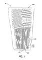
- FIG. 1 is a diagrammatic representation of a first airfoil portion.
- FIG. 2 is a diagrammatic cross-sectioned partial view of first and second airfoil portions joined together.
- FIG. 3 is another diagrammatic cross-sectioned partial view of first and second airfoil portions joined together.
- FIG. 4 is a diagrammatic cross-sectioned partial view shown in FIG. 3 , filled with a support material.
- FIG. 5 is a flow diagram illustrating the present method.
- FIG. 6 illustrates an example of an attachment process for attaching the first and second airfoil portions that can be used with the exemplary disclosure.
- a hollow airfoil 30 includes a first airfoil portion 230A and a second airfoil portion 230B, and at least one internal cavity 250.
- the first and second airfoil portions 230A, 230B may be formed from a material such as, but not limited to, aluminum, an aluminum alloy, and all other weldable alloy systems.
- the first airfoil portion 230A has a wall 231 defined by an exterior surface 242 and an interior surface 240, and one or more ribs 254 extending out from the interior surface 240.
- the second airfoil portion 230B has a wall 233 defined by an exterior surface 244 and an interior surface 246.
- FIG. 2 illustrates an example of a second airfoil portion 230B having one or more ribs 260 extending out from the interior surface 246.
- FIG. 3 illustrates an example wherein the ribs 254 extending out from the interior surface 240 of the first airfoil portion 230A extend across to the interior surface 246 of the second airfoil portion 230B.
- the second airfoil portion 230B is configured as a substantially flat panel.
- the first and second airfoil portions 230A, 230B may have any combinations of ribs extending out from one or the other, or from both.
- the at least one internal cavity 250 is defined by the interior surface 240 of the first portion wall 230A, one or more of the ribs 254, 260, and the interior surface 246 of the second portion wall 230B.
- the diagrammatic examples shown in FIGS. 2 and 3 include a plurality of internal cavities 250.
- the airfoil 30 includes at least one exterior port 256 (see FIG. 1 ) extending between the at least one internal cavity 250 and the exterior of the hollow airfoil 30.
- the exterior port 256 provides fluid communication between the internal cavity 250 and the exterior of the hollow airfoil as will be explained below. In those embodiments having more than one internal cavity 250, which internal cavities 250 receive a support material 600 as is described below, all of such internal cavities 250 are in fluid communication with at least one exterior port 256.
- the support material 600 may be any material that: a) can be disposed within the at least one internal cavity 250; b) provides sufficient support for a structural member (e.g., a rib 254) of the first and/or second airfoil portions 230A, 230B to facilitate preventing substantial deformation of the member during the process of attaching the first and second airfoil portions 230A, 230B together; and c) may be removed from the at least one internal cavity through the exterior port 256 after the airfoil portions 230A, 230B are attached together.
- the specific properties of the support material 600 may vary depending upon the material of the airfoil portions and/or the attachment process (e.g., friction stir welding).
- an acceptable support material 600 is a ceramic material (e.g., fused silica, alumina, silica-alumino silicate, etc.) used in conjunction with a binder (e.g., wax, phenolic urethane, etc.). These binder systems may be removed through the airfoil 30 by acid erosion or through thermal cycling of the welded component.
- a binder e.g., wax, phenolic urethane, etc.
- Another example of an acceptable support material 600 is a low melt metallic alloy that can be removed by thermal liquification. It should be noted that these are examples of acceptable support materials, and the exemplary method is not limited to these materials.
- the amount of support material 600 disposed within the internal cavity 250 is dictated by the amount of support needed by the airfoil member, and the amount of support provided by the support material 600. In FIG. 4 , the internal cavities 250 are shown filled with support material 600. In other applications, it may be possible to use an amount of support material 600 that does not fill
- Blocks 500 and 510 represent providing the first airfoil portion 230A and providing the second airfoil portion 230B.
- Block 520 represents the step of disposing a support material within the at least one internal cavity in a position to permit the support material to structurally support the one or more ribs.
- Block 530 represents attaching the first and second airfoil portions 230A, 230B to one another, for example using a welding or other bonding process.
- An example of a bonding process that is acceptable for joining first and second airfoil portions 230A, 230B including an aluminum alloy is friction stir welding.
- the exemplary method implements support material to facilitate, for example, a) joining the airfoil portions together along interfaces that cannot be visually inspected during the joining process; b) decreasing the deformation of members (particularly relatively thin members) during the joining process; and c) enabling the use of joining processes that otherwise would not be feasible.
- friction stir welding is a process that uses a rotating tool 712 to join two work pieces or to repair cracks in a single work piece.
- the rotating tool 712 is contacted with the workpiece 444 in a manner that produces frictional heating in an amount sufficient to weld the workpieces 444, 454 together. Because the process relies upon friction, some amount of force is applied to the workpieces 444, 454, which force can cause undesirable deformation of the workpieces to be joined.
- Friction stir welding is a well known process and further details are not necessary to provide an enabling disclosure. As indicated above, the exemplary method is not limited to using friction stir welding as a process for attaching the first and second airfoil portions 230A, 230B together.
- Block 540 represents the step of removing the support material from the now joined first and second airfoil portions 230A, 230B.
- the support material 600 is a ceramic type material
- certain acids may be used to erode the ceramic disposed within the at least one internal cavity 250, and permit the erosion products to pass out of the internal cavity 250, and subsequently out of the airfoil 30 via the exterior port 256.
- the support material 600 is a low-melt metallic alloy
- the support material 600 may be removed from the airfoil 30 by heating the airfoil and contained low-melt alloy support material 600 to a temperature in a range above the melt point of the support material 600 and below a temperature detrimental to the airfoil 30 material. Once the low-melt alloy support material is liquefied, it can be removed from the airfoil 30 through the exterior port 256.
Landscapes
- Engineering & Computer Science (AREA)
- Mechanical Engineering (AREA)
- Architecture (AREA)
- General Engineering & Computer Science (AREA)
- Pressure Welding/Diffusion-Bonding (AREA)
- Turbine Rotor Nozzle Sealing (AREA)
Abstract
A hollow airfoil (30) and a method for manufacturing a hollow airfoil are provided. The method includes the steps of: providing (500) a first airfoil portion (230A), which first portion has a wall (231) with an interior surface (240) and an exterior surface (242), and one or more ribs (254) extending out from the interior surface; providing (510) a second airfoil portion (230B) having a wall (233) with an interior surface (246) and an exterior surface (244);wherein the first airfoil portion and the second airfoil portion have mating geometries in which the one or more ribs extend between the interior surfaces of the walls of the first and second airfoil portion to form at least one internal cavity (250) defined by the interior surface of the first portion wall, one or more of the ribs, and the interior surface of the second portion wall, and wherein the airfoil includes at least one exterior port (256) disposed in one of the first airfoil portion or the second airfoil portion, or is formed between the first and second airfoil portions, which at least one exterior port is in fluid communication with the at least one cavity; disposing (520) a support material (600) within the at least one internal cavity allowing the support material to be in contact with the one or more ribs, which support material is operative to structurally support the one or more ribs; attaching (530) the first and second airfoil portions together; and removing (540) the support material from the at least one internal cavity through the at least one exterior port.
Description
- This disclosure relates to methods and apparatus for manufacturing hollow airfoils generally, and more particularly to a method and apparatus for providing support within an internal cavity of the airfoil during the manufacturing process.
- A gas turbine engine includes a fan section, a compressor section, a combustor and a turbine section disposed along an axially extending centerline. The fan section includes a plurality of rotor assemblies rotatable about the centerline, and at least one stator assembly. Each rotor assembly has a rotor disk and plurality of fan blades extending radially out from the disk. The fan blades are disposed within a gas path where they are operable to transfer energy to air passing therethrough, thus producing useful thrust. Each fan blade has an airfoil portion, and in most instances an inner platform as well. Fan blades that can be selectively mounted on the disk include a base (sometimes referred to as a "root") that engages the disk for attachment purposes.
- Some gas turbine fan blades (typically referred to as a "hollow fan blade") have an internal cavity disposed within the airfoil section, which cavity is formed between a pressure side wall and a suction side wall, and a plurality of ribs extending between the walls. Typically, hollow fan blades are manufactured by joining a first portion of the airfoil together with a second portion of the airfoil. Welding is a known method of attachment. One of the problems associated with welding is that the airfoil portions can distort during the process and create misalignments between mating portions, thereby making it difficult to properly join the portions. This is particularly problematic in those instances where the mating parts cannot be visually inspected.
- According to an aspect of the present invention, a method for manufacturing a hollow airfoil is provided, including the steps of: a) providing a first airfoil portion, which first portion has a wall with an interior surface and an exterior surface, and one or more ribs extending out from the interior surface; b) providing a second airfoil portion having a wall with an interior surface and an exterior surface, wherein the first and second airfoil portions have mating geometries in which the one or more ribs extend between the interior surfaces of the walls of the first and second airfoil portions to form at least one internal cavity, and wherein the hollow airfoil includes at least one exterior port disposed in one of the first airfoil portion or the second airfoil portion, or is formed between the first and second airfoil portions, which at least one exterior port is in fluid communication with the at least one cavity; c) disposing a support material within the at least one of the internal cavity allowing the support material to be in contact with the one or more ribs, which support material is operative to structurally support the one or more ribs; d) attaching the first and second airfoil portions together; and e) removing the support material from the at least one internal cavity through the at least one exterior port.
- According to another aspect of the invention a hollow airfoil is provided. The airfoil includes a first airfoil portion, a second airfoil portion, and a support material. The first airfoil portion has a wall with an interior surface and an exterior surface, and one or more ribs extending out from the interior surface. The second airfoil portion has a wall with an interior surface and an exterior surface, and is attached to the first airfoil portion. The first and second airfoil portions have mating geometries in which the one or more ribs extend between the interior surfaces of the walls of the first and second airfoil portion to form at least one internal cavity defined by the interior surface of the first portion wall, one or more of the ribs, and the interior surface of the second portion wall. The airfoil includes at least one exterior port disposed in one of the first airfoil portion or the second airfoil portion, or is formed between the first and second airfoil portions, which at least one exterior port is in fluid communication with the at least one cavity. The support material is disposed within the at least one internal cavity in contact with the one or more ribs. The support material is operative to structurally support the one or more ribs.
-
FIG. 1 is a diagrammatic representation of a first airfoil portion. -
FIG. 2 is a diagrammatic cross-sectioned partial view of first and second airfoil portions joined together. -
FIG. 3 is another diagrammatic cross-sectioned partial view of first and second airfoil portions joined together. -
FIG. 4 is a diagrammatic cross-sectioned partial view shown inFIG. 3 , filled with a support material. -
FIG. 5 is a flow diagram illustrating the present method. -
FIG. 6 illustrates an example of an attachment process for attaching the first and second airfoil portions that can be used with the exemplary disclosure. - Referring to
FIGS. 1-3 , ahollow airfoil 30 includes afirst airfoil portion 230A and asecond airfoil portion 230B, and at least oneinternal cavity 250. The first andsecond airfoil portions first airfoil portion 230A has awall 231 defined by anexterior surface 242 and aninterior surface 240, and one ormore ribs 254 extending out from theinterior surface 240. Thesecond airfoil portion 230B has awall 233 defined by anexterior surface 244 and aninterior surface 246.FIG. 2 illustrates an example of asecond airfoil portion 230B having one ormore ribs 260 extending out from theinterior surface 246.FIG. 3 illustrates an example wherein theribs 254 extending out from theinterior surface 240 of thefirst airfoil portion 230A extend across to theinterior surface 246 of thesecond airfoil portion 230B. In this example, thesecond airfoil portion 230B is configured as a substantially flat panel. The first andsecond airfoil portions internal cavity 250 is defined by theinterior surface 240 of thefirst portion wall 230A, one or more of theribs interior surface 246 of thesecond portion wall 230B. The diagrammatic examples shown inFIGS. 2 and 3 include a plurality ofinternal cavities 250. - The
airfoil 30 includes at least one exterior port 256 (seeFIG. 1 ) extending between the at least oneinternal cavity 250 and the exterior of thehollow airfoil 30. Theexterior port 256 provides fluid communication between theinternal cavity 250 and the exterior of the hollow airfoil as will be explained below. In those embodiments having more than oneinternal cavity 250, whichinternal cavities 250 receive asupport material 600 as is described below, all of suchinternal cavities 250 are in fluid communication with at least oneexterior port 256. - The support material 600 (illustrated in
FIG. 4 ) may be any material that: a) can be disposed within the at least oneinternal cavity 250; b) provides sufficient support for a structural member (e.g., a rib 254) of the first and/orsecond airfoil portions second airfoil portions exterior port 256 after theairfoil portions support material 600 may vary depending upon the material of the airfoil portions and/or the attachment process (e.g., friction stir welding). An example of anacceptable support material 600 is a ceramic material (e.g., fused silica, alumina, silica-alumino silicate, etc.) used in conjunction with a binder (e.g., wax, phenolic urethane, etc.). These binder systems may be removed through theairfoil 30 by acid erosion or through thermal cycling of the welded component. Another example of anacceptable support material 600 is a low melt metallic alloy that can be removed by thermal liquification. It should be noted that these are examples of acceptable support materials, and the exemplary method is not limited to these materials. The amount ofsupport material 600 disposed within theinternal cavity 250 is dictated by the amount of support needed by the airfoil member, and the amount of support provided by thesupport material 600. InFIG. 4 , theinternal cavities 250 are shown filled withsupport material 600. In other applications, it may be possible to use an amount ofsupport material 600 that does not fill theinternal cavities 250. - Now referring to
FIG. 5 , a flow diagram is provided illustrating an example of the exemplary method. Each block represents a step of the method. The order of the steps is not fixed and the steps may be performed in a variety of different orders.Blocks first airfoil portion 230A and providing thesecond airfoil portion 230B.Block 520 represents the step of disposing a support material within the at least one internal cavity in a position to permit the support material to structurally support the one or more ribs.Block 530 represents attaching the first andsecond airfoil portions second airfoil portions - Now referring to
FIG. 6 , friction stir welding, as known in the art, is a process that uses a rotatingtool 712 to join two work pieces or to repair cracks in a single work piece. Therotating tool 712 is contacted with theworkpiece 444 in a manner that produces frictional heating in an amount sufficient to weld theworkpieces workpieces second airfoil portions -
Block 540 represents the step of removing the support material from the now joined first andsecond airfoil portions support material 600 is a ceramic type material, certain acids may be used to erode the ceramic disposed within the at least oneinternal cavity 250, and permit the erosion products to pass out of theinternal cavity 250, and subsequently out of theairfoil 30 via theexterior port 256. Similarly, if thesupport material 600 is a low-melt metallic alloy, thesupport material 600 may be removed from theairfoil 30 by heating the airfoil and contained low-meltalloy support material 600 to a temperature in a range above the melt point of thesupport material 600 and below a temperature detrimental to theairfoil 30 material. Once the low-melt alloy support material is liquefied, it can be removed from theairfoil 30 through theexterior port 256. - While various embodiments of the method for providing internal support during friction stir welding have been described, it will be apparent to those of ordinary skill in the art that many more embodiments and implementations are possible within the scope of the method. Accordingly, the method is not to be restricted except in light of the attached claims and their equivalents.
Claims (13)
- A method for manufacturing a hollow airfoil, comprising the steps of:providing (500) a first airfoil portion (230A), which first portion has a wall (231) with an interior surface (240) and an exterior surface (242), and one or more ribs (254) extending out from the interior surface;providing (510) a second airfoil portion (230B) having a wall (233) with an interior surface (246) and an exterior surface (244);wherein the first airfoil portion and the second airfoil portion have mating geometries in which the one or more ribs extend between the interior surfaces of the walls of the first and second airfoil portion to form at least one internal cavity (250) defined by the interior surface of the first portion wall, one or more of the ribs, and the interior surface of the second portion wall, and wherein the airfoil includes at least one exterior port (256) disposed in one of the first airfoil portion or the second airfoil portion, or is formed between the first and second airfoil portions, which at least one exterior port is in fluid communication with the at least one cavity;disposing (520) a support material (600) within the at least one internal cavity allowing the support material to be in contact with the one or more ribs, which support material is operative to structurally support the one or more ribs;attaching (530) the first and second airfoil portions together; andremoving (540) the support material from the at least one internal cavity through the at least one exterior port.
- The method of claim 1, wherein disposing the support material comprises providing a ceramic material.
- The method of claim 2, wherein providing the ceramic material includes providing at least one of fused silica, alumina, and silica-aluminosilicate.
- The method of claim 2 or 3, wherein removing the support material comprises eroding the ceramic material, and passing the ceramic material out of the airfoil through the exterior port.
- The method of claim 1, 2, 3 or 4, wherein the first and second airfoil portions comprise aluminum.
- The method of any preceding claim, wherein the first and second airfoil portions comprise a weldable alloy.
- The method of claim 6, wherein the weldable alloy is an aluminum alloy.
- The method of any preceding claim, wherein disposing the support material comprises at least partially filling the at least one internal cavity with the support material.
- The method of any preceding claim, wherein attaching the first and second airfoil portions together comprises friction stir welding.
- The method of any preceding claim, wherein disposing the support material comprises providing a material having a melting point temperature lower than a melting point temperature of the first and second airfoil portions.
- The method of claim 10, wherein providing the material comprises providing a metal alloy.
- The method of claim 10 or 11, wherein removing the support material comprises elevating the support material to a temperature at or above the melting point temperature of the support material, and draining a resultant liquefied support material through the exterior port.
- A hollow airfoil, comprising:a first airfoil portion (230A), which first portion has a wall (231) with an interior surface (240) and an exterior surface (242), and one or more ribs (254) extending out from the interior surface;a second airfoil portion (230B) having a wall (233) with an interior surface (246) and an exterior surface (244), attached to the first airfoil portion;wherein the first airfoil portion and the second airfoil portion have mating geometries in which the one or more ribs extend between the interior surfaces of the walls of the first and second airfoil portion to form at least one internal cavity (250) defined by the interior surface of the first portion wall, one or more of the ribs, and the interior surface of the second portion wall, and wherein the airfoil includes at least one exterior port (256) disposed in one of the first airfoil portion or the second airfoil portion, or is formed between the first and second airfoil portions, which at least one exterior port is in fluid communication with the at least one cavity; and
a support material (600) disposed within the at least one internal cavity in contact with the one or more ribs, which support material is operative to structurally support the one or more ribs.
Applications Claiming Priority (1)
| Application Number | Priority Date | Filing Date | Title |
|---|---|---|---|
| US12/415,307 US8240999B2 (en) | 2009-03-31 | 2009-03-31 | Internally supported airfoil and method for internally supporting a hollow airfoil during manufacturing |
Publications (1)
| Publication Number | Publication Date |
|---|---|
| EP2239083A1 true EP2239083A1 (en) | 2010-10-13 |
Family
ID=42289017
Family Applications (1)
| Application Number | Title | Priority Date | Filing Date |
|---|---|---|---|
| EP10250661A Withdrawn EP2239083A1 (en) | 2009-03-31 | 2010-03-30 | Internally supported airfoil and method for internally supporting a hollow airfoil during manufacturing. |
Country Status (2)
| Country | Link |
|---|---|
| US (1) | US8240999B2 (en) |
| EP (1) | EP2239083A1 (en) |
Cited By (4)
| Publication number | Priority date | Publication date | Assignee | Title |
|---|---|---|---|---|
| EP2634367A1 (en) * | 2012-02-29 | 2013-09-04 | United Technologies Corporation | Method of applying liquid adhesive to a surface of a metallic fan blade |
| EP2573324A3 (en) * | 2011-09-23 | 2015-05-06 | United Technologies Corporation | Hollow fan blade with channel configuration to reduce stress |
| EP2573322A3 (en) * | 2011-09-23 | 2015-05-20 | United Technologies Corporation | Fan blade |
| EP3712377A1 (en) * | 2019-03-20 | 2020-09-23 | United Technologies Corporation | Method of forming gas turbine engine components |
Families Citing this family (5)
| Publication number | Priority date | Publication date | Assignee | Title |
|---|---|---|---|---|
| FR2978196B1 (en) | 2011-07-20 | 2016-12-09 | Snecma | TURBOMACHINE AUB COMPRISING A PLATE REPORTED ON A MAIN PART |
| EP2900923B1 (en) * | 2012-09-25 | 2019-12-25 | United Technologies Corporation | Airfoil array with vanes that differ in geometry according to geometry classes |
| GB201316732D0 (en) | 2013-09-20 | 2013-11-06 | Rolls Royce Plc | Manufacture of filled aerofoil |
| GB201316731D0 (en) * | 2013-09-20 | 2013-11-06 | Rolls Royce Plc | Manufacture of hollow aerofoil |
| US20180038386A1 (en) * | 2016-08-08 | 2018-02-08 | United Technologies Corporation | Fan blade with composite cover |
Citations (4)
| Publication number | Priority date | Publication date | Assignee | Title |
|---|---|---|---|---|
| US2326430A (en) * | 1940-06-14 | 1943-08-10 | Gen Motors Corp | Propeller manufacture |
| JPH10230375A (en) * | 1997-02-21 | 1998-09-02 | Showa Alum Corp | Friction stir welding of metal hollow materials |
| EP1596036A1 (en) * | 2004-05-14 | 2005-11-16 | General Electric Company | Friction stir welded hollow airfoils and method therefor |
| DE102007023151A1 (en) * | 2007-05-16 | 2008-11-27 | Mtu Aero Engines Gmbh | Method for joining of metal components, involves joining of metal components having cavity with corresponding joint faces of gas turbine by low- or high-frequency pressure welding process |
Family Cites Families (17)
| Publication number | Priority date | Publication date | Assignee | Title |
|---|---|---|---|---|
| US6158957A (en) * | 1998-12-23 | 2000-12-12 | United Technologies Corporation | Thermal barrier removal process |
| US6637500B2 (en) * | 2001-10-24 | 2003-10-28 | United Technologies Corporation | Cores for use in precision investment casting |
| US6908690B2 (en) * | 2002-04-29 | 2005-06-21 | The Boeing Company | Method and apparatus for friction stir welding |
| US6966354B2 (en) * | 2003-12-05 | 2005-11-22 | United Technologies Corporation | Shelling apparatus and methods for investment casting |
| US7334333B2 (en) * | 2004-01-26 | 2008-02-26 | United Technologies Corporation | Method for making a hollow fan blade with machined internal cavities |
| US7070391B2 (en) * | 2004-01-26 | 2006-07-04 | United Technologies Corporation | Hollow fan blade for gas turbine engine |
| US20050211408A1 (en) * | 2004-03-25 | 2005-09-29 | Bullied Steven J | Single crystal investment cast components and methods of making same |
| US7951580B2 (en) * | 2004-04-21 | 2011-05-31 | The Regents Of The University Of California | Automated, programmable, high throughput, multiplexed assay system for cellular and biological assays |
| US7172012B1 (en) * | 2004-07-14 | 2007-02-06 | United Technologies Corporation | Investment casting |
| US7144220B2 (en) * | 2004-07-30 | 2006-12-05 | United Technologies Corporation | Investment casting |
| US7438527B2 (en) * | 2005-04-22 | 2008-10-21 | United Technologies Corporation | Airfoil trailing edge cooling |
| US7240821B2 (en) * | 2005-07-21 | 2007-07-10 | The Boeing Company | Method for joining at least two adjoining work-pieces by friction stir and/or friction stir spot welding |
| US20070074839A1 (en) * | 2005-10-03 | 2007-04-05 | United Technologies Corporation | Method for manufacturing a pattern for a hollow component |
| US7243700B2 (en) * | 2005-10-27 | 2007-07-17 | United Technologies Corporation | Method for casting core removal |
| US20080169270A1 (en) * | 2007-01-17 | 2008-07-17 | United Technologies Corporation | Method of removing a case layer from a metal alloy |
| US20080311421A1 (en) * | 2007-06-15 | 2008-12-18 | United Technologies Corporation | Friction stir welded structures derived from AL-RE-TM alloys |
| US20080308610A1 (en) * | 2007-06-15 | 2008-12-18 | United Technologies Corporation | Hollow structures formed with friction stir welding |
-
2009
- 2009-03-31 US US12/415,307 patent/US8240999B2/en active Active
-
2010
- 2010-03-30 EP EP10250661A patent/EP2239083A1/en not_active Withdrawn
Patent Citations (4)
| Publication number | Priority date | Publication date | Assignee | Title |
|---|---|---|---|---|
| US2326430A (en) * | 1940-06-14 | 1943-08-10 | Gen Motors Corp | Propeller manufacture |
| JPH10230375A (en) * | 1997-02-21 | 1998-09-02 | Showa Alum Corp | Friction stir welding of metal hollow materials |
| EP1596036A1 (en) * | 2004-05-14 | 2005-11-16 | General Electric Company | Friction stir welded hollow airfoils and method therefor |
| DE102007023151A1 (en) * | 2007-05-16 | 2008-11-27 | Mtu Aero Engines Gmbh | Method for joining of metal components, involves joining of metal components having cavity with corresponding joint faces of gas turbine by low- or high-frequency pressure welding process |
Cited By (6)
| Publication number | Priority date | Publication date | Assignee | Title |
|---|---|---|---|---|
| EP2573324A3 (en) * | 2011-09-23 | 2015-05-06 | United Technologies Corporation | Hollow fan blade with channel configuration to reduce stress |
| EP2573322A3 (en) * | 2011-09-23 | 2015-05-20 | United Technologies Corporation | Fan blade |
| EP2634367A1 (en) * | 2012-02-29 | 2013-09-04 | United Technologies Corporation | Method of applying liquid adhesive to a surface of a metallic fan blade |
| EP3712377A1 (en) * | 2019-03-20 | 2020-09-23 | United Technologies Corporation | Method of forming gas turbine engine components |
| US11033993B2 (en) | 2019-03-20 | 2021-06-15 | Raytheon Technologies Corporation | Method of forming gas turbine engine components |
| EP4234884A3 (en) * | 2019-03-20 | 2023-12-06 | RTX Corporation | Method of forming gas turbine engine components |
Also Published As
| Publication number | Publication date |
|---|---|
| US8240999B2 (en) | 2012-08-14 |
| US20100247322A1 (en) | 2010-09-30 |
Similar Documents
| Publication | Publication Date | Title |
|---|---|---|
| US8240999B2 (en) | Internally supported airfoil and method for internally supporting a hollow airfoil during manufacturing | |
| US7966707B2 (en) | Method for repairing superalloy components using inserts | |
| EP1759799B1 (en) | Method for forming or remanufacturing a turbine engine component | |
| EP1074331B1 (en) | Method for repairing superralloy castings using a metallurgically bonded tapered plug | |
| EP2286953B1 (en) | A method of joining components using sinterable powder and relative displacement of the components | |
| EP1721697B2 (en) | Superalloy repair methods and inserts | |
| US10689989B2 (en) | Method for friction-welding a blade to a turbomachine vane, including a surfacing process | |
| EP1055480A2 (en) | Repair of a recess in an article surface | |
| IT9021627A1 (en) | METHOD FOR MANUFACTURING DOUBLE ALLOY TURBINE DISCS | |
| EP2025864A2 (en) | Airfoil replacement repair | |
| US20130004320A1 (en) | Method of rotated airfoils | |
| US20140140859A1 (en) | Uber-cooled multi-alloy integrally bladed rotor | |
| EP1953347A2 (en) | Non-stablug stator apparatus and assembly method | |
| JP2014534079A (en) | Method of joining or repairing superalloy structures using resistance brazing of convex parts and corresponding superalloy components | |
| KR102302909B1 (en) | Turbine blade repair method using additive manufacturing | |
| EP1952917B1 (en) | A method of manufacturing a component by consolidating powder material | |
| US8322595B2 (en) | Joining method and resultant article | |
| US20190376396A1 (en) | Turbine blisk and process of making | |
| KR102423535B1 (en) | Repair coupon for mechanical equipment | |
| EP2020274A1 (en) | Apparatus and method for reparing airfoil tips |
Legal Events
| Date | Code | Title | Description |
|---|---|---|---|
| PUAI | Public reference made under article 153(3) epc to a published international application that has entered the european phase |
Free format text: ORIGINAL CODE: 0009012 |
|
| AK | Designated contracting states |
Kind code of ref document: A1 Designated state(s): AT BE BG CH CY CZ DE DK EE ES FI FR GB GR HR HU IE IS IT LI LT LU LV MC MK MT NL NO PL PT RO SE SI SK SM TR |
|
| AX | Request for extension of the european patent |
Extension state: AL BA ME RS |
|
| 17P | Request for examination filed |
Effective date: 20110413 |
|
| STAA | Information on the status of an ep patent application or granted ep patent |
Free format text: STATUS: THE APPLICATION HAS BEEN WITHDRAWN |
|
| 18W | Application withdrawn |
Effective date: 20140611 |