EP2239041A2 - System and method for obtaining an optimal estimate of NOx emissions - Google Patents
System and method for obtaining an optimal estimate of NOx emissions Download PDFInfo
- Publication number
- EP2239041A2 EP2239041A2 EP10157273A EP10157273A EP2239041A2 EP 2239041 A2 EP2239041 A2 EP 2239041A2 EP 10157273 A EP10157273 A EP 10157273A EP 10157273 A EP10157273 A EP 10157273A EP 2239041 A2 EP2239041 A2 EP 2239041A2
- Authority
- EP
- European Patent Office
- Prior art keywords
- time
- signal
- estimate
- nox emission
- responsive signal
- Prior art date
- Legal status (The legal status is an assumption and is not a legal conclusion. Google has not performed a legal analysis and makes no representation as to the accuracy of the status listed.)
- Granted
Links
Images


Classifications
-
- B—PERFORMING OPERATIONS; TRANSPORTING
- B01—PHYSICAL OR CHEMICAL PROCESSES OR APPARATUS IN GENERAL
- B01D—SEPARATION
- B01D53/00—Separation of gases or vapours; Recovering vapours of volatile solvents from gases; Chemical or biological purification of waste gases, e.g. engine exhaust gases, smoke, fumes, flue gases, aerosols
- B01D53/34—Chemical or biological purification of waste gases
- B01D53/74—General processes for purification of waste gases; Apparatus or devices specially adapted therefor
- B01D53/86—Catalytic processes
- B01D53/8621—Removing nitrogen compounds
- B01D53/8625—Nitrogen oxides
-
- B—PERFORMING OPERATIONS; TRANSPORTING
- B01—PHYSICAL OR CHEMICAL PROCESSES OR APPARATUS IN GENERAL
- B01D—SEPARATION
- B01D53/00—Separation of gases or vapours; Recovering vapours of volatile solvents from gases; Chemical or biological purification of waste gases, e.g. engine exhaust gases, smoke, fumes, flue gases, aerosols
- B01D53/30—Controlling by gas-analysis apparatus
-
- B—PERFORMING OPERATIONS; TRANSPORTING
- B01—PHYSICAL OR CHEMICAL PROCESSES OR APPARATUS IN GENERAL
- B01D—SEPARATION
- B01D53/00—Separation of gases or vapours; Recovering vapours of volatile solvents from gases; Chemical or biological purification of waste gases, e.g. engine exhaust gases, smoke, fumes, flue gases, aerosols
- B01D53/34—Chemical or biological purification of waste gases
- B01D53/74—General processes for purification of waste gases; Apparatus or devices specially adapted therefor
- B01D53/86—Catalytic processes
- B01D53/90—Injecting reactants
-
- F—MECHANICAL ENGINEERING; LIGHTING; HEATING; WEAPONS; BLASTING
- F01—MACHINES OR ENGINES IN GENERAL; ENGINE PLANTS IN GENERAL; STEAM ENGINES
- F01N—GAS-FLOW SILENCERS OR EXHAUST APPARATUS FOR MACHINES OR ENGINES IN GENERAL; GAS-FLOW SILENCERS OR EXHAUST APPARATUS FOR INTERNAL-COMBUSTION ENGINES
- F01N3/00—Exhaust or silencing apparatus having means for purifying, rendering innocuous, or otherwise treating exhaust
- F01N3/08—Exhaust or silencing apparatus having means for purifying, rendering innocuous, or otherwise treating exhaust for rendering innocuous
- F01N3/10—Exhaust or silencing apparatus having means for purifying, rendering innocuous, or otherwise treating exhaust for rendering innocuous by thermal or catalytic conversion of noxious components of exhaust
- F01N3/18—Exhaust or silencing apparatus having means for purifying, rendering innocuous, or otherwise treating exhaust for rendering innocuous by thermal or catalytic conversion of noxious components of exhaust characterised by methods of operation; Control
- F01N3/20—Exhaust or silencing apparatus having means for purifying, rendering innocuous, or otherwise treating exhaust for rendering innocuous by thermal or catalytic conversion of noxious components of exhaust characterised by methods of operation; Control specially adapted for catalytic conversion
- F01N3/206—Adding periodically or continuously substances to exhaust gases for promoting purification, e.g. catalytic material in liquid form, NOx reducing agents
- F01N3/208—Control of selective catalytic reduction [SCR], e.g. by adjusting the dosing of reducing agent
-
- F—MECHANICAL ENGINEERING; LIGHTING; HEATING; WEAPONS; BLASTING
- F01—MACHINES OR ENGINES IN GENERAL; ENGINE PLANTS IN GENERAL; STEAM ENGINES
- F01N—GAS-FLOW SILENCERS OR EXHAUST APPARATUS FOR MACHINES OR ENGINES IN GENERAL; GAS-FLOW SILENCERS OR EXHAUST APPARATUS FOR INTERNAL-COMBUSTION ENGINES
- F01N9/00—Electrical control of exhaust gas treating apparatus
- F01N9/005—Electrical control of exhaust gas treating apparatus using models instead of sensors to determine operating characteristics of exhaust systems, e.g. calculating catalyst temperature instead of measuring it directly
-
- F—MECHANICAL ENGINEERING; LIGHTING; HEATING; WEAPONS; BLASTING
- F23—COMBUSTION APPARATUS; COMBUSTION PROCESSES
- F23J—REMOVAL OR TREATMENT OF COMBUSTION PRODUCTS OR COMBUSTION RESIDUES; FLUES
- F23J15/00—Arrangements of devices for treating smoke or fumes
- F23J15/003—Arrangements of devices for treating smoke or fumes for supplying chemicals to fumes, e.g. using injection devices
-
- G—PHYSICS
- G05—CONTROLLING; REGULATING
- G05B—CONTROL OR REGULATING SYSTEMS IN GENERAL; FUNCTIONAL ELEMENTS OF SUCH SYSTEMS; MONITORING OR TESTING ARRANGEMENTS FOR SUCH SYSTEMS OR ELEMENTS
- G05B13/00—Adaptive control systems, i.e. systems automatically adjusting themselves to have a performance which is optimum according to some preassigned criterion
- G05B13/02—Adaptive control systems, i.e. systems automatically adjusting themselves to have a performance which is optimum according to some preassigned criterion electric
- G05B13/04—Adaptive control systems, i.e. systems automatically adjusting themselves to have a performance which is optimum according to some preassigned criterion electric involving the use of models or simulators
- G05B13/048—Adaptive control systems, i.e. systems automatically adjusting themselves to have a performance which is optimum according to some preassigned criterion electric involving the use of models or simulators using a predictor
-
- G—PHYSICS
- G05—CONTROLLING; REGULATING
- G05B—CONTROL OR REGULATING SYSTEMS IN GENERAL; FUNCTIONAL ELEMENTS OF SUCH SYSTEMS; MONITORING OR TESTING ARRANGEMENTS FOR SUCH SYSTEMS OR ELEMENTS
- G05B17/00—Systems involving the use of models or simulators of said systems
- G05B17/02—Systems involving the use of models or simulators of said systems electric
-
- B—PERFORMING OPERATIONS; TRANSPORTING
- B01—PHYSICAL OR CHEMICAL PROCESSES OR APPARATUS IN GENERAL
- B01D—SEPARATION
- B01D2251/00—Reactants
- B01D2251/20—Reductants
- B01D2251/206—Ammonium compounds
- B01D2251/2062—Ammonia
-
- F—MECHANICAL ENGINEERING; LIGHTING; HEATING; WEAPONS; BLASTING
- F01—MACHINES OR ENGINES IN GENERAL; ENGINE PLANTS IN GENERAL; STEAM ENGINES
- F01N—GAS-FLOW SILENCERS OR EXHAUST APPARATUS FOR MACHINES OR ENGINES IN GENERAL; GAS-FLOW SILENCERS OR EXHAUST APPARATUS FOR INTERNAL-COMBUSTION ENGINES
- F01N2560/00—Exhaust systems with means for detecting or measuring exhaust gas components or characteristics
- F01N2560/02—Exhaust systems with means for detecting or measuring exhaust gas components or characteristics the means being an exhaust gas sensor
- F01N2560/026—Exhaust systems with means for detecting or measuring exhaust gas components or characteristics the means being an exhaust gas sensor for measuring or detecting NOx
-
- F—MECHANICAL ENGINEERING; LIGHTING; HEATING; WEAPONS; BLASTING
- F01—MACHINES OR ENGINES IN GENERAL; ENGINE PLANTS IN GENERAL; STEAM ENGINES
- F01N—GAS-FLOW SILENCERS OR EXHAUST APPARATUS FOR MACHINES OR ENGINES IN GENERAL; GAS-FLOW SILENCERS OR EXHAUST APPARATUS FOR INTERNAL-COMBUSTION ENGINES
- F01N2900/00—Details of electrical control or of the monitoring of the exhaust gas treating apparatus
- F01N2900/04—Methods of control or diagnosing
- F01N2900/0411—Methods of control or diagnosing using a feed-forward control
-
- F—MECHANICAL ENGINEERING; LIGHTING; HEATING; WEAPONS; BLASTING
- F01—MACHINES OR ENGINES IN GENERAL; ENGINE PLANTS IN GENERAL; STEAM ENGINES
- F01N—GAS-FLOW SILENCERS OR EXHAUST APPARATUS FOR MACHINES OR ENGINES IN GENERAL; GAS-FLOW SILENCERS OR EXHAUST APPARATUS FOR INTERNAL-COMBUSTION ENGINES
- F01N2900/00—Details of electrical control or of the monitoring of the exhaust gas treating apparatus
- F01N2900/06—Parameters used for exhaust control or diagnosing
- F01N2900/14—Parameters used for exhaust control or diagnosing said parameters being related to the exhaust gas
- F01N2900/1402—Exhaust gas composition
-
- Y—GENERAL TAGGING OF NEW TECHNOLOGICAL DEVELOPMENTS; GENERAL TAGGING OF CROSS-SECTIONAL TECHNOLOGIES SPANNING OVER SEVERAL SECTIONS OF THE IPC; TECHNICAL SUBJECTS COVERED BY FORMER USPC CROSS-REFERENCE ART COLLECTIONS [XRACs] AND DIGESTS
- Y02—TECHNOLOGIES OR APPLICATIONS FOR MITIGATION OR ADAPTATION AGAINST CLIMATE CHANGE
- Y02T—CLIMATE CHANGE MITIGATION TECHNOLOGIES RELATED TO TRANSPORTATION
- Y02T10/00—Road transport of goods or passengers
- Y02T10/10—Internal combustion engine [ICE] based vehicles
- Y02T10/12—Improving ICE efficiencies
-
- Y—GENERAL TAGGING OF NEW TECHNOLOGICAL DEVELOPMENTS; GENERAL TAGGING OF CROSS-SECTIONAL TECHNOLOGIES SPANNING OVER SEVERAL SECTIONS OF THE IPC; TECHNICAL SUBJECTS COVERED BY FORMER USPC CROSS-REFERENCE ART COLLECTIONS [XRACs] AND DIGESTS
- Y02—TECHNOLOGIES OR APPLICATIONS FOR MITIGATION OR ADAPTATION AGAINST CLIMATE CHANGE
- Y02T—CLIMATE CHANGE MITIGATION TECHNOLOGIES RELATED TO TRANSPORTATION
- Y02T10/00—Road transport of goods or passengers
- Y02T10/10—Internal combustion engine [ICE] based vehicles
- Y02T10/40—Engine management systems
Definitions
- the invention relates generally to systems for monitoring NOx emissions, and more particularly to systems for obtaining an optimal estimate of the emissions.
- a CEM system typically includes a gas analyzer installed either directly in the exhaust stack, or connected via an extractive system which extracts a gas sample from the exhaust stack and conveys it to an analyzer at grade level.
- Continuous emissions monitoring systems are quite expensive, particularly due to the installation cost and demanding maintenance and calibration requirements of the gas analyzers.
- PEMS built in the past to predict various combustion and emission parameters from continuous industrial processes and to calculate process or combustion efficiency for compliance reporting and process optimization purposes.
- the PEMS is "trained" by monitoring multiple inputs such as pressures, temperatures, flow rates, etc., and one or more output parameters such as, but not limited to, NOx and carbon monoxide. After training, in normal operation, the PEMS monitors only the multiple inputs and calculates estimated output parameter values that closely match the actual pollutant levels.
- Methodologies used in the past include nonlinear statistical, neural network, eigenvalue, stochastic, and other methods of processing the input parameters from available field devices and to predict process emission rates and combustion or process efficiency.
- the PEMS are complicated, relatively costly, and difficult to implement.
- the systems also typically require retraining with the support of specialized staff from the system provider to adjust the proprietary model to the real-world conditions encountered in the field.
- an improved system for obtaining an optimal estimate of NOx emissions is desirable to address one or more of the aforementioned issues.
- a control system for providing an optimal estimate of NOx emission in an exhaust during a selective catalytic reduction process.
- the control system includes a continuous emission monitoring sensor configured to generate a responsive signal representing a first estimate of NOx emission; wherein the responsive signal has a first time lag between a time of measurement of NOx emission and the time when the corresponding responsive signal is made available by the continuous emission monitoring sensor, and the continuous emission monitoring sensor has a first time constant.
- the control system also includes a virtual sensor configured to generate a relatively faster responsive signal representing a second estimate of NOx emission.
- the control system further includes a processor that includes a time delay compensation circuit configured to introduce a second time lag in the relatively faster responsive signal, wherein the second time lag matches the first time lag.
- the processor also includes a low pass filter circuit coupled to the time delay compensating circuit, wherein the low pass filter circuit has a second time constant matching the first time constant to generate a time delayed signal representing a third estimate of NOx emission.
- the processor is further configured to subtract the time delayed signal from the summation of the responsive signal and the relatively faster responsive signal to generate the optimal estimate of the NOx emission, wherein the optimal estimate is fed as a feedforward signal into an injection system in the selective catalytic reduction process.
- a method for providing an optimal estimate of NOx emission in an exhaust during a selective catalytic reduction process includes generating a responsive signal representing a first estimate of NOx emission via a continuous emission monitoring sensor; the responsive signal comprising a first time lag and the continuous emission monitoring sensor comprising a first time constant.
- the method also includes generating a relatively faster responsive signal representing a second estimate of NOx emission via a virtual sensor.
- the method further includes introducing a second time lag in the relatively faster responsive signal via a time delay compensation circuit; the second time lag matching the first time lag.
- the method also includes generating a time delayed signal representing a third estimate of NOx emission via a low pass filter circuit coupled to the time delay compensation circuit, the low pass filter circuit including a second time constant matching the first time constant.
- the method also includes subtracting the time delayed signal from a summation of the responsive signal and the relatively faster responsive signal via a processor to generate the optimal estimate of the NOx emission, wherein the optimal estimate is fed as a feedforward signal into an injection system in the selective catalytic reduction process.
- a method for generating an accurate control signal includes receiving a first input signal via a first sensor; the first input signal characterized by a first time lag and the first sensor comprising a first time constant.
- the method also includes receiving a second input signal via a second sensor; the second input signal characterized by zero time lag.
- the method further includes introducing a second time delay in the second input signal, wherein the second time delay matches the first time delay.
- the method also includes transmitting the second input signal with the second time delay via a low pass filter, wherein the low pass filter includes a second time constant, and the second time constant matches the first time constant.
- the method further includes subtracting the time delayed signal output via the low pass filter, from a summation of the first input signal and the second input signal to generate the accurate control signal, wherein the accurate control signal is fed as a feedforward signal into an injection system.
- various embodiments of the invention include a system and method for obtaining an optimal estimate of NOx emissions.
- the system and method include a technique to introduce a time delay in a relatively faster, responsive signal and filter the signal via a low pass filter.
- the term 'NOx emission' includes emission of gases such as, but not limited to, nitrogen oxide and nitrogen dioxide.
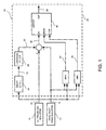
- FIG. 1 is a schematic illustration of a control system 10 for obtaining an optimal estimate of NOx emissions in an exhaust during a selective catalytic reduction process.
- the system 10 includes a continuous emission monitoring sensor (CEMS) 12 having a first time constant to generate a responsive signal 14 representing a first estimate of NOx emission.
- the first time constant includes a range between about 60 seconds to about 180 seconds.
- the responsive signal 14 has a first time lag between a time of measurement of NOx emission and the time when the corresponding responsive signal is made available by the CEMS sensor 12.
- the first time lag typically occurs due to a transportation period and processing time of a sample in the exhaust. In one embodiment, the first time lag is greater than about 45 seconds.
- a virtual sensor 18 generates a relatively faster, responsive signal 20 representing a second estimate of NOx emission.
- the term 'relatively faster' refers to a faster response time as compared to the responsive signal 14.
- the relatively faster, responsive signal is considered relatively inaccurate compared to the responsive signal 14.
- the second estimate is determined based upon a model reflecting a predetermined relationship between control parameters and NOx emissions, wherein the control parameters include ambient humidity, manifold pressure, manifold temperature, fuel rate, and engine speed associated with an engine, for example.
- the model may be adjusted based on a determination of whether the predicted NOx values meet predetermined criteria associated with actual NOx values measured.
- the model or the virtual sensor may be associated with a neural network that accepts determined control parameters as inputs and produces a predicted NOx value as an output.
- a processor 22 including a time delay compensation circuit 24 introduces a second time lag in the relatively faster, responsive signal 20 resulting in signal 26, wherein the second time lag in the signal 26 is equal to the first time lag in the responsive signal 14.
- a low pass filter circuit 28 having a second time constant matching the first time constant is coupled to the time delay compensation circuit 24 to generate an additional time delayed signal 32 representing a third estimate of NOx emission.
- the low pass filter circuit 28 is a first order low pass filter circuit.
- the signal 32 is subtracted from a sum of the responsive signal 14 and the relatively faster, responsive signal 20 to output a signal 36. In effect, the signal 32 removes contribution of the relatively inaccurate component from the relatively faster, responsive signal 20.
- the third component completely cancels contribution of the second component and the resulting estimate is the accurate first component referring to the responsive signal 14.
- logic of obtaining signal 36 representing an accurate estimate of NOx emission has similarities to a Smith Predictor control algorithm.
- the Smith Predictor control algorithm is often employed in feedback control of systems having "dead times.” In such a scheme, the outer feedback control loop feeds the output back to the input, as usual. However, this loop alone would not provide satisfactory control, because of the delay; this loop is feeding back outdated information. Intuitively, for the time during which no fresh information is available, the system is controlled by the inner feedback loop which contains a predictor of what the (unobservable) output of the plant currently is. Accordingly, a Smith-Predictor like algorithm is appropriate for use herein, because there are time delays involved in obtaining an optimal estimate.
- the invention is distinct from the typical Smith Predictor control algorithm in that accurate estimate of NOx emissions is generated for the purposes of feedforward control instead of feedback control.
- a limiter 40 further receives the signal 36 to ensure that magnitude of an output signal 38 is maintained within a certain range.
- a maximum value 42 and a minimum value 44 of the responsive signals 14 and the relatively faster, responsive signals 20 are computed respectively.
- the maximum value 42 and the minimum value 44 are further fed into the limiter 40.
- the limiter 40 thus, limits the input signal 36 between the maximum value 42 and the minimum value 44.
- the optimal estimate is fed as a feedforward signal for an injection system of a gas, for example, ammonia, in the selective catalytic reduction process.
- the selective catalytic reduction process is performed in a power plant. It should be noted that although two sensors have been illustrated here, any number of sensors may be employed.
- processor for performing the processing tasks of the invention.
- processor is intended to denote any machine capable of performing the calculations, or computations, necessary to perform the tasks of the invention.
- processor is intended to denote any machine that is capable of accepting a structured input and of processing the input in accordance with prescribed rules to produce an output.
- phrase "configured to” as used herein means that the processor is equipped with a combination of hardware and software for performing the tasks of the invention, as will be understood by those skilled in the art.
- FIG. 2 is a graphical comparison 70 of simulated results for optimal estimates of NOX emissions obtained via a CEMS sensor, a virtual sensor, and the control system 10 in FIG. 1 for a time range of about 600 sec.
- the X-axis 72 represents time in seconds and the Y-axis 74 represents estimate of NOx emission in ppm (parts per million).
- curve 76 represents an actual estimate of NOx emission. The actual estimate rises as a step function from an initial value of to a steady state of 120 ppm.
- Curve 78 represents an estimate of NOx emission from a CEMS. The estimate varies from an initial value of 0 ppm for about 100 sec to reach a steady state of about 120 ppm after about 400 sec.
- curve 80 represents an estimate of NOx emission obtained from a virtual sensor.
- the estimate rises as a step function from an initial value of 0 ppm to a steady value of 100 ppm.
- curve 82 represents an estimate of NOx emission measured from the control system 10 in FIG. 1 . As illustrated herein, the signal remains at 100 ppm for about 100 sec and further increases rapidly to reach a steady value of the actual estimate of 120 ppm at around 200 sec.
- FIG. 3 is a flow chart representing steps in a method 100 for providing an optimal estimate of NOx emission in an exhaust during a selective catalytic reduction process.
- the method 100 includes generating a responsive signal representing a first estimate of NOx emission via a continuous emission monitoring sensor; wherein the responsive signal includes a first time lag and the continuous emission monitoring sensor includes a first time constant in step 102.
- a relatively faster responsive signal representing a second estimate of NOx emission is generated via a virtual sensor in step 104.
- the steps 102 and 104 are performed simultaneously.
- a second time lag is introduced in the relatively faster responsive signal via a time delay compensation circuit; wherein the second time lag matches the first time lag in step 106.
- a time delayed signal representing a third estimate of NOx emission is generated in step 108 via a low pass filter circuit coupled to the time delay compensation circuit, wherein the low pass filter circuit includes a second time constant matching the first time constant.
- the time delayed signal is subtracted from a summation of the responsive signal and the relatively faster responsive signal via a processor to generate the optimal estimate of the NOx emission in step 110.
- the optimal estimate of the NOx emission is fed into an injection system in the selective catalytic reduction process in step 112.
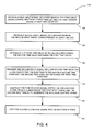
- FIG. 4 is a flow chart representing steps in a method 120 for generating an accurate signal.
- the method 120 includes receiving a first input signal via a first sensor; the first input signal characterized by a first time lag and the first sensor having a first time constant in step 122.
- the first sensor includes continuous emission monitoring sensor.
- a second input signal is received via a second sensor in step 124, wherein the second input signal is characterized by zero time lag.
- the second sensor includes a virtual sensor.
- a second time delay is introduced in the second input signal in step 126, wherein the second time delay matches the first time delay.
- the second input signal is transmitted with the second time delay via a low pass filter in step 128, wherein the low pass filter includes a second time constant that matches the first time constant.
- the low pass filter is a first order low pass filter.
- the time delayed signal output via the low pass filter is subtracted from a summation of the first input signal and the second input signal to generate the accurate control signal in step 130.
- the time delayed signal output is subtracted via a processor.
- the accurate control signal is further fed into an injection system in step 132.
- the various embodiments of a system and method for obtaining an optimal estimate for NOx emissions described above thus provide a way to achieve a convenient and efficient means for determining amount of fluid to be injected in a selective catalytic reduction process.
- the system and method also enable maintaining and regulating amount of NOx emitted below an acceptable level. Further, the system and technique also allows for cost effective means for estimating NOx.
- first order low pass filter described with respect to one embodiment can be adapted for use with a control system employing more than two sensors described with respect to another.
- various features described, as well as other known equivalents for each feature can be mixed and matched by one of ordinary skill in this art to construct additional systems and techniques in accordance with principles of this disclosure.
Landscapes
- Engineering & Computer Science (AREA)
- Chemical & Material Sciences (AREA)
- Chemical Kinetics & Catalysis (AREA)
- Analytical Chemistry (AREA)
- Environmental & Geological Engineering (AREA)
- Health & Medical Sciences (AREA)
- General Chemical & Material Sciences (AREA)
- Oil, Petroleum & Natural Gas (AREA)
- Mechanical Engineering (AREA)
- General Engineering & Computer Science (AREA)
- Automation & Control Theory (AREA)
- Biomedical Technology (AREA)
- Combustion & Propulsion (AREA)
- Physics & Mathematics (AREA)
- General Physics & Mathematics (AREA)
- Artificial Intelligence (AREA)
- Toxicology (AREA)
- Computer Vision & Pattern Recognition (AREA)
- Evolutionary Computation (AREA)
- Medical Informatics (AREA)
- Software Systems (AREA)
- Exhaust Gas After Treatment (AREA)
- Exhaust Gas Treatment By Means Of Catalyst (AREA)
- Feedback Control In General (AREA)
Abstract
Description
- The invention relates generally to systems for monitoring NOx emissions, and more particularly to systems for obtaining an optimal estimate of the emissions.
- Public awareness has increased with respect to the environment, and primary pollutants such as nitrogen oxides and sulfur dioxide are currently regulated in most industries. A great deal of attention in recent years has been spent on addressing the monitoring requirements of these regulations, in order to minimize the discharge of noxious gases into the atmosphere by industrial facilities.
- One technique for ensuring correct monitoring of NOx has been to implement continuous emissions monitoring systems (CEMS). A CEM system typically includes a gas analyzer installed either directly in the exhaust stack, or connected via an extractive system which extracts a gas sample from the exhaust stack and conveys it to an analyzer at grade level. Continuous emissions monitoring systems are quite expensive, particularly due to the installation cost and demanding maintenance and calibration requirements of the gas analyzers.
- In order to target the challenges associated with CEMS, solutions have been developed that do away with the gas analyzer and instead uses a computer based model for predicting the NOx emissions. The model uses as input a number of monitored parameters from the energy or fuel conversion process, such as temperatures and pressures. These systems are referred to as predictive or parametric emissions measurement systems (PEMS).
- There have been PEMS built in the past to predict various combustion and emission parameters from continuous industrial processes and to calculate process or combustion efficiency for compliance reporting and process optimization purposes. Typically, the PEMS is "trained" by monitoring multiple inputs such as pressures, temperatures, flow rates, etc., and one or more output parameters such as, but not limited to, NOx and carbon monoxide. After training, in normal operation, the PEMS monitors only the multiple inputs and calculates estimated output parameter values that closely match the actual pollutant levels. Methodologies used in the past include nonlinear statistical, neural network, eigenvalue, stochastic, and other methods of processing the input parameters from available field devices and to predict process emission rates and combustion or process efficiency. However, the PEMS are complicated, relatively costly, and difficult to implement. The systems also typically require retraining with the support of specialized staff from the system provider to adjust the proprietary model to the real-world conditions encountered in the field.
- Therefore, an improved system for obtaining an optimal estimate of NOx emissions is desirable to address one or more of the aforementioned issues.
- According to various aspects of the present invention, a control system for providing an optimal estimate of NOx emission in an exhaust during a selective catalytic reduction process is provided. The control system includes a continuous emission monitoring sensor configured to generate a responsive signal representing a first estimate of NOx emission; wherein the responsive signal has a first time lag between a time of measurement of NOx emission and the time when the corresponding responsive signal is made available by the continuous emission monitoring sensor, and the continuous emission monitoring sensor has a first time constant. The control system also includes a virtual sensor configured to generate a relatively faster responsive signal representing a second estimate of NOx emission. The control system further includes a processor that includes a time delay compensation circuit configured to introduce a second time lag in the relatively faster responsive signal, wherein the second time lag matches the first time lag. The processor also includes a low pass filter circuit coupled to the time delay compensating circuit, wherein the low pass filter circuit has a second time constant matching the first time constant to generate a time delayed signal representing a third estimate of NOx emission. The processor is further configured to subtract the time delayed signal from the summation of the responsive signal and the relatively faster responsive signal to generate the optimal estimate of the NOx emission, wherein the optimal estimate is fed as a feedforward signal into an injection system in the selective catalytic reduction process.
- According to various aspects, a method for providing an optimal estimate of NOx emission in an exhaust during a selective catalytic reduction process is provided. The method includes generating a responsive signal representing a first estimate of NOx emission via a continuous emission monitoring sensor; the responsive signal comprising a first time lag and the continuous emission monitoring sensor comprising a first time constant. The method also includes generating a relatively faster responsive signal representing a second estimate of NOx emission via a virtual sensor. The method further includes introducing a second time lag in the relatively faster responsive signal via a time delay compensation circuit; the second time lag matching the first time lag. The method also includes generating a time delayed signal representing a third estimate of NOx emission via a low pass filter circuit coupled to the time delay compensation circuit, the low pass filter circuit including a second time constant matching the first time constant. The method also includes subtracting the time delayed signal from a summation of the responsive signal and the relatively faster responsive signal via a processor to generate the optimal estimate of the NOx emission, wherein the optimal estimate is fed as a feedforward signal into an injection system in the selective catalytic reduction process.
- According to various aspects, a method for generating an accurate control signal is also provided. The method includes receiving a first input signal via a first sensor; the first input signal characterized by a first time lag and the first sensor comprising a first time constant. The method also includes receiving a second input signal via a second sensor; the second input signal characterized by zero time lag. The method further includes introducing a second time delay in the second input signal, wherein the second time delay matches the first time delay. The method also includes transmitting the second input signal with the second time delay via a low pass filter, wherein the low pass filter includes a second time constant, and the second time constant matches the first time constant. The method further includes subtracting the time delayed signal output via the low pass filter, from a summation of the first input signal and the second input signal to generate the accurate control signal, wherein the accurate control signal is fed as a feedforward signal into an injection system.
- Various features, aspects, and advantages of the present invention will become better understood when the following detailed description is read with reference to the accompanying drawings in which like characters represent like parts throughout the drawings, wherein:
-
FIG. 1 is a schematic illustration of a control system for providing an optimal estimate of NOx emission in an exhaust during a selective catalytic reduction process in accordance with an embodiment of the invention. -
FIG. 2 is a graphical comparison of simulated results for optimal estimates of NOx emissions obtained via a CEMS sensor, a virtual sensor, and the control system inFIG. 1 . -
FIG. 3 is a flow chart representing steps in a method for providing an optimal estimate of NOx emission in an exhaust during a selective catalytic reduction process in accordance with an embodiment of the invention. -
FIG. 4 is a flow chart representing steps in a method for generating an accurate signal in accordance with an embodiment of the invention. - As discussed in detail below, various embodiments of the invention include a system and method for obtaining an optimal estimate of NOx emissions. The system and method include a technique to introduce a time delay in a relatively faster, responsive signal and filter the signal via a low pass filter. As used herein, the term 'NOx emission' includes emission of gases such as, but not limited to, nitrogen oxide and nitrogen dioxide.
-
FIG. 1 is a schematic illustration of acontrol system 10 for obtaining an optimal estimate of NOx emissions in an exhaust during a selective catalytic reduction process. Thesystem 10 includes a continuous emission monitoring sensor (CEMS) 12 having a first time constant to generate aresponsive signal 14 representing a first estimate of NOx emission. In a particular embodiment, the first time constant includes a range between about 60 seconds to about 180 seconds. Theresponsive signal 14 has a first time lag between a time of measurement of NOx emission and the time when the corresponding responsive signal is made available by the CEMS sensor 12. The first time lag typically occurs due to a transportation period and processing time of a sample in the exhaust. In one embodiment, the first time lag is greater than about 45 seconds. - A
virtual sensor 18 generates a relatively faster,responsive signal 20 representing a second estimate of NOx emission. The term 'relatively faster' refers to a faster response time as compared to theresponsive signal 14. The relatively faster, responsive signal is considered relatively inaccurate compared to theresponsive signal 14. In a particular embodiment, the second estimate is determined based upon a model reflecting a predetermined relationship between control parameters and NOx emissions, wherein the control parameters include ambient humidity, manifold pressure, manifold temperature, fuel rate, and engine speed associated with an engine, for example. Furthermore, the model may be adjusted based on a determination of whether the predicted NOx values meet predetermined criteria associated with actual NOx values measured. In another embodiment, the model or the virtual sensor may be associated with a neural network that accepts determined control parameters as inputs and produces a predicted NOx value as an output. - Furthermore, a
processor 22 including a timedelay compensation circuit 24 introduces a second time lag in the relatively faster,responsive signal 20 resulting insignal 26, wherein the second time lag in thesignal 26 is equal to the first time lag in theresponsive signal 14. A lowpass filter circuit 28 having a second time constant matching the first time constant is coupled to the timedelay compensation circuit 24 to generate an additional timedelayed signal 32 representing a third estimate of NOx emission. In one embodiment, the lowpass filter circuit 28 is a first order low pass filter circuit. Thesignal 32 is subtracted from a sum of theresponsive signal 14 and the relatively faster,responsive signal 20 to output asignal 36. In effect, thesignal 32 removes contribution of the relatively inaccurate component from the relatively faster,responsive signal 20. In a steady state, the third component completely cancels contribution of the second component and the resulting estimate is the accurate first component referring to theresponsive signal 14. - In one embodiment, logic of obtaining
signal 36 representing an accurate estimate of NOx emission has similarities to a Smith Predictor control algorithm. The Smith Predictor control algorithm is often employed in feedback control of systems having "dead times." In such a scheme, the outer feedback control loop feeds the output back to the input, as usual. However, this loop alone would not provide satisfactory control, because of the delay; this loop is feeding back outdated information. Intuitively, for the time during which no fresh information is available, the system is controlled by the inner feedback loop which contains a predictor of what the (unobservable) output of the plant currently is. Accordingly, a Smith-Predictor like algorithm is appropriate for use herein, because there are time delays involved in obtaining an optimal estimate. Applying a lag and a low pass filter to the faster responsive signal generates a 'prediction' of the CEMS NOx signal. The invention is distinct from the typical Smith Predictor control algorithm in that accurate estimate of NOx emissions is generated for the purposes of feedforward control instead of feedback control. - A
limiter 40 further receives thesignal 36 to ensure that magnitude of anoutput signal 38 is maintained within a certain range. Amaximum value 42 and aminimum value 44 of theresponsive signals 14 and the relatively faster,responsive signals 20 are computed respectively. Themaximum value 42 and theminimum value 44 are further fed into thelimiter 40. Thelimiter 40, thus, limits theinput signal 36 between themaximum value 42 and theminimum value 44. In a particular embodiment, the optimal estimate is fed as a feedforward signal for an injection system of a gas, for example, ammonia, in the selective catalytic reduction process. In another embodiment, the selective catalytic reduction process is performed in a power plant. It should be noted that although two sensors have been illustrated here, any number of sensors may be employed. - It should be noted that embodiments of the invention are not limited to any particular processor for performing the processing tasks of the invention. The term "processor," as that term is used herein, is intended to denote any machine capable of performing the calculations, or computations, necessary to perform the tasks of the invention. The term "processor" is intended to denote any machine that is capable of accepting a structured input and of processing the input in accordance with prescribed rules to produce an output. It should also be noted that the phrase "configured to" as used herein means that the processor is equipped with a combination of hardware and software for performing the tasks of the invention, as will be understood by those skilled in the art.
-
FIG. 2 is agraphical comparison 70 of simulated results for optimal estimates of NOX emissions obtained via a CEMS sensor, a virtual sensor, and thecontrol system 10 inFIG. 1 for a time range of about 600 sec. TheX-axis 72 represents time in seconds and the Y-axis 74 represents estimate of NOx emission in ppm (parts per million). As illustrated herein,curve 76 represents an actual estimate of NOx emission. The actual estimate rises as a step function from an initial value of to a steady state of 120 ppm.Curve 78 represents an estimate of NOx emission from a CEMS. The estimate varies from an initial value of 0 ppm for about 100 sec to reach a steady state of about 120 ppm after about 400 sec. Similarly,curve 80 represents an estimate of NOx emission obtained from a virtual sensor. The estimate rises as a step function from an initial value of 0 ppm to a steady value of 100 ppm. Furthermore, thecurve 82 represents an estimate of NOx emission measured from thecontrol system 10 inFIG. 1 . As illustrated herein, the signal remains at 100 ppm for about 100 sec and further increases rapidly to reach a steady value of the actual estimate of 120 ppm at around 200 sec. -
FIG. 3 is a flow chart representing steps in amethod 100 for providing an optimal estimate of NOx emission in an exhaust during a selective catalytic reduction process. Themethod 100 includes generating a responsive signal representing a first estimate of NOx emission via a continuous emission monitoring sensor; wherein the responsive signal includes a first time lag and the continuous emission monitoring sensor includes a first time constant instep 102. A relatively faster responsive signal representing a second estimate of NOx emission is generated via a virtual sensor instep 104. In a particular embodiment, thesteps step 106. A time delayed signal representing a third estimate of NOx emission is generated instep 108 via a low pass filter circuit coupled to the time delay compensation circuit, wherein the low pass filter circuit includes a second time constant matching the first time constant. The time delayed signal is subtracted from a summation of the responsive signal and the relatively faster responsive signal via a processor to generate the optimal estimate of the NOx emission instep 110. The optimal estimate of the NOx emission is fed into an injection system in the selective catalytic reduction process instep 112. -
FIG. 4 is a flow chart representing steps in amethod 120 for generating an accurate signal. Themethod 120 includes receiving a first input signal via a first sensor; the first input signal characterized by a first time lag and the first sensor having a first time constant instep 122. In one embodiment, the first sensor includes continuous emission monitoring sensor. A second input signal is received via a second sensor instep 124, wherein the second input signal is characterized by zero time lag. In a particular embodiment, the second sensor includes a virtual sensor. A second time delay is introduced in the second input signal instep 126, wherein the second time delay matches the first time delay. The second input signal is transmitted with the second time delay via a low pass filter instep 128, wherein the low pass filter includes a second time constant that matches the first time constant. In one embodiment, the low pass filter is a first order low pass filter. The time delayed signal output via the low pass filter is subtracted from a summation of the first input signal and the second input signal to generate the accurate control signal instep 130. In one embodiment, the time delayed signal output is subtracted via a processor. The accurate control signal is further fed into an injection system instep 132. - The various embodiments of a system and method for obtaining an optimal estimate for NOx emissions described above thus provide a way to achieve a convenient and efficient means for determining amount of fluid to be injected in a selective catalytic reduction process. The system and method also enable maintaining and regulating amount of NOx emitted below an acceptable level. Further, the system and technique also allows for cost effective means for estimating NOx.
- It is to be understood that not necessarily all such objects or advantages described above may be achieved in accordance with any particular embodiment. Thus, for example, those skilled in the art will recognize that the systems and techniques described herein may be embodied or carried out in a manner that achieves or optimizes one advantage or group of advantages as taught herein without necessarily achieving other objects or advantages as may be taught or suggested herein.
- Furthermore, the skilled artisan will recognize the interchangeability of various features from different embodiments. For example, the use of a first order low pass filter described with respect to one embodiment can be adapted for use with a control system employing more than two sensors described with respect to another. Similarly, the various features described, as well as other known equivalents for each feature, can be mixed and matched by one of ordinary skill in this art to construct additional systems and techniques in accordance with principles of this disclosure.
- While the invention has been described in detail in connection with only a limited number of embodiments, it should be readily understood that the invention is not limited to such disclosed embodiments. Rather, the invention can be modified to incorporate any number of variations, alterations, substitutions or equivalent arrangements not heretofore described, but which are commensurate with the spirit and scope of the invention. Additionally, while various embodiments of the invention have been described, it is to be understood that aspects of the invention may include only some of the described embodiments. Accordingly, the invention is not to be seen as limited by the foregoing description, but is only limited by the scope of the appended claims.
- Various aspects and embodiments of the present invention are defined by the following numbered clauses:
- 1. A control system for providing an optimal estimate of NOx emission in an exhaust during a selective catalytic reduction process, the control system comprising:
- a continuous emission monitoring sensor configured to generate a responsive signal representing a first estimate of NOx emission; the responsive signal having a first time lag between a time of measurement of NOx emission and the time when the corresponding responsive signal is made available by the continuous emission monitoring sensor, and the continuous emission monitoring sensor having a first time constant;
- a virtual sensor configured to generate a relatively faster responsive signal representing a second estimate of NOx emission; and
- a processor comprising:
- a time delay compensation circuit configured to introduce a second time lag in the relatively faster responsive signal, the second time lag matching the first time lag;
- a low pass filter circuit coupled to the time delay compensating circuit, the low pass filter circuit having a second time constant matching the first time constant to generate a time delayed signal representing a third estimate of NOx emission; the processor further configured to subtract the time delayed signal from the summation of the responsive signal and the relatively faster responsive signal to generate the optimal estimate of the NOx emission, wherein the optimal estimate is fed as a feedforward signal into an injection system in the selective catalytic reduction process.
- 2. The system of clause 1, wherein the NOx emission comprises nitrogen oxide and nitrogen dioxide.
- 3. The system of any preceding clause, wherein the optimal estimate is fed as a feedforward signal for an injection system of a gas in the selective catalytic reduction process.
- 4. The system of any preceding clause, wherein the gas comprises ammonia.
- 5. The system of any preceding clause, wherein the processor comprises a Smith predictor like algorithm.
- 6. The system of any preceding clause, wherein the selective catalytic reduction process is performed in a power plant.
- 7. The system of any preceding clause, wherein the first time lag comprises a time greater than about 45 seconds.
- 8. The system of any preceding clause, wherein the first time constant comprises a range between about 60 seconds to about 180 seconds.
- 9. The system of any preceding clause, wherein the first time lag occurs due to transportation period and processing time of sample in the exhaust.
- 10. A method for providing an optimal estimate of NOx emission in an exhaust during a selective catalytic reduction process, the method comprising:
- generating a responsive signal representing a first estimate of NOx emission via a continuous emission monitoring sensor; the responsive signal comprising a first time lag and the continuous emission monitoring sensor having a first time constant;
- generating a relatively faster responsive signal representing a second estimate of NOx emission via a virtual sensor;
- introducing a second time lag in the relatively faster responsive signal via a time delay compensation circuit; the second time lag matching the first time lag;
- generating a time delayed signal representing a third estimate of NOx emission via a low pass filter circuit coupled to the time delay compensation circuit, the low pass filter circuit having a second time constant matching the first time constant;
- subtracting the time delayed signal from a summation of the responsive signal and the relatively faster responsive signal via a processor to generate the optimal estimate of the NOx emission; and
- feeding the optimal estimate of the NOx emission into an injection system in the selective catalytic reduction process.
- 11. The method of any preceding clause, wherein the first time constant comprises a range between about 60 seconds to about 180 seconds.
- 12. The method of any preceding clause, wherein the second time constant comprises a range between about 60 seconds to about 180 seconds.
- 13. A method for generating an accurate control signal comprising:
- receiving a first input signal via a first sensor; the first input signal characterized by a first time lag and the first sensor comprising a first time constant;
- receiving a second input signal via a second sensor; the second input signal characterized by zero time lag;
- introducing a second time delay in the second input signal, the second time delay matching the first time delay;
- transmitting the second input signal with the second time delay via a low pass filter, the low pass filter comprising a second time constant, the second time constant matching the first time constant; and
- subtracting the time delayed signal output via the low pass filter, from a summation of the first input signal and the second input signal to generate the accurate control signal; and
- feeding the accurate control signal into an injection system.
- 14. The method of any preceding clause, wherein the first sensor comprises a continuous emission monitoring sensor.
- 15. The method of any preceding clause, wherein said subtracting comprises subtracting via a processor.
Claims (10)
- A control system (10) for providing an optimal estimate of NOx emission in an exhaust during a selective catalytic reduction process, the control system (10) comprising:a continuous emission monitoring sensor (12) configured to generate a responsive signal (14) representing a first estimate of NOx emission; the responsive signal (14) having a first time lag between a time of measurement of NOx emission and the time when the corresponding responsive signal is made available by the continuous emission monitoring sensor (12), and the continuous emission monitoring sensor having a first time constant;a virtual sensor (18) configured to generate a relatively faster responsive signal representing a second estimate of NOx emission; anda processor (22) comprising:a time delay compensation circuit (24) configured to introduce a second time lag in the relatively faster responsive signal, the second time lag matching the first time lag; anda low pass filter circuit (28) coupled to the time delay compensating circuit (24), the low pass filter circuit (28) having a second time constant matching the first time constant to generate a time delayed signal representing a third estimate of NOx emission; the processor (22) further configured to subtract the time delayed signal from the summation of the responsive signal and the relatively faster responsive signal to generate the optimal estimate of the NOx emission, wherein the optimal estimate is fed as a feedforward signal into an injection system in the selective catalytic reduction process.
- The system (10) of claim 1, wherein the optimal estimate is fed as a feedforward signal for an injection system of a gas in the selective catalytic reduction process.
- The system (10) of any preceding claim, wherein the first time lag comprises a time greater than about 45 seconds.
- The system (10) of any preceding claim, wherein the first time constant comprises a range between about 60 seconds to about 180 seconds.
- The system (10) of any preceding claim, wherein the first time lag occurs due to transportation period and processing time of sample in the exhaust.
- A method (100) for providing an optimal estimate of NOx emission in an exhaust during a selective catalytic reduction process, the method comprising:generating (102) a responsive signal representing a first estimate of NOx emission via a continuous emission monitoring sensor; the responsive signal comprising a first time lag and the continuous emission monitoring sensor having a first time constant;generating (104) a relatively faster responsive signal representing a second estimate of NOx emission via a virtual sensor;introducing (106) a second time lag in the relatively faster responsive signal via a time delay compensation circuit; the second time lag matching the first time lag;generating (108) a time delayed signal representing a third estimate of NOx emission via a low pass filter circuit coupled to the time delay compensation circuit, the low pass filter circuit having a second time constant matching the first time constant;subtracting (110) the time delayed signal from a summation of the responsive signal and the relatively faster responsive signal via a processor to generate the optimal estimate of the NOx emission; andfeeding (112) the optimal estimate of the NOx emission into an injection system in the selective catalytic reduction process.
- The method (100) of claim 6, wherein the first time constant comprises a range between about 60 seconds to about 180 seconds.
- The method (100) of claim 6 or claim 7, wherein the second time constant comprises a range between about 60 seconds to about 180 seconds.
- A method (120) for generating an accurate control signal comprising:receiving (122) a first input signal via a first sensor; the first input signal characterized by a first time lag and the first sensor comprising a first time constant;receiving (124) a second input signal via a second sensor; the second input signal characterized by zero time lag;introducing (126) a second time delay in the second input signal, the second time delay matching the first time delay;transmitting (128) the second input signal with the second time delay via a low pass filter, the low pass filter comprising a second time constant, the second time constant matching the first time constant; andsubtracting (130) the time delayed signal output via the low pass filter, from a summation of the first input signal and the second input signal to generate the accurate control signal; andfeeding (132) the accurate control signal into an injection system.
- The method (120) of claim 9, wherein the first sensor comprises a continuous emission monitoring sensor.
Applications Claiming Priority (1)
| Application Number | Priority Date | Filing Date | Title |
|---|---|---|---|
| US12/419,382 US8140248B2 (en) | 2009-04-07 | 2009-04-07 | System and method for obtaining an optimal estimate of NOx emissions |
Publications (3)
| Publication Number | Publication Date |
|---|---|
| EP2239041A2 true EP2239041A2 (en) | 2010-10-13 |
| EP2239041A3 EP2239041A3 (en) | 2013-06-12 |
| EP2239041B1 EP2239041B1 (en) | 2014-08-13 |
Family
ID=42312825
Family Applications (1)
| Application Number | Title | Priority Date | Filing Date |
|---|---|---|---|
| EP10157273.3A Active EP2239041B1 (en) | 2009-04-07 | 2010-03-23 | System and method for obtaining an optimal estimate of NOx emissions |
Country Status (2)
| Country | Link |
|---|---|
| US (1) | US8140248B2 (en) |
| EP (1) | EP2239041B1 (en) |
Cited By (1)
| Publication number | Priority date | Publication date | Assignee | Title |
|---|---|---|---|---|
| DE102009028873B4 (en) * | 2009-08-26 | 2021-04-22 | Robert Bosch Gmbh | Process for the sensor and computer model-based determination of the raw NOx emissions of an internal combustion engine |
Families Citing this family (17)
| Publication number | Priority date | Publication date | Assignee | Title |
|---|---|---|---|---|
| US8301356B2 (en) * | 2008-10-06 | 2012-10-30 | GM Global Technology Operations LLC | Engine out NOx virtual sensor using cylinder pressure sensor |
| JP5333120B2 (en) * | 2009-09-25 | 2013-11-06 | 富士通株式会社 | Engine control program, method and apparatus |
| US8510024B2 (en) * | 2010-09-09 | 2013-08-13 | GM Global Technology Operations LLC | Model-based diagnostic method and system for a selective reduction catalyst device in a vehicle |
| KR101317413B1 (en) * | 2011-11-22 | 2013-10-10 | 서울대학교산학협력단 | System and method for controlling nox |
| US9777637B2 (en) | 2012-03-08 | 2017-10-03 | General Electric Company | Gas turbine fuel flow measurement using inert gas |
| US10071344B2 (en) | 2015-10-19 | 2018-09-11 | Paccar Inc | Reductant dosing control using prediction of exhaust species in selective catalytic reduction |
| JP7048216B2 (en) * | 2017-03-29 | 2022-04-05 | 三菱重工業株式会社 | Information processing equipment, information processing methods and programs |
| CN107803114B (en) * | 2017-12-04 | 2020-06-16 | 烟台龙源电力技术股份有限公司 | Denitration control system and control method and control device thereof |
| CN108170129A (en) * | 2017-12-29 | 2018-06-15 | 凯龙高科技股份有限公司 | A kind of controller develops test platform |
| CN110414089A (en) * | 2019-07-10 | 2019-11-05 | 一汽解放汽车有限公司 | The simulated prediction method of vehicle PEMS discharge based on Engine Universal Characteristics |
| CN111266004B (en) * | 2020-03-20 | 2021-07-23 | 大唐环境产业集团股份有限公司 | SCR denitration reactor inlet NOx delay estimation system |
| CN111722611A (en) * | 2020-05-15 | 2020-09-29 | 北京国电富通科技发展有限责任公司 | An intelligent ash removal adjustment system and method based on big data of unit parameters |
| CN111584015B (en) * | 2020-05-27 | 2021-09-10 | 大唐环境产业集团股份有限公司 | Denitration system inlet NOx measurement delay estimation method and device |
| DE102020214474B4 (en) | 2020-11-18 | 2025-11-27 | Robert Bosch Gesellschaft mit beschränkter Haftung | Method and apparatus for creating an emission model of an internal combustion engine |
| CN112576351B (en) * | 2020-11-27 | 2022-04-26 | 潍柴动力股份有限公司 | Method, device, equipment and medium for obtaining engine nitrogen oxide model value |
| CN113655816B (en) * | 2021-06-30 | 2023-11-21 | 武汉钢铁有限公司 | Flow control method and computer-readable storage medium for ladle bottom blowing argon system |
| CN115575580B (en) * | 2022-10-19 | 2025-09-09 | 东北电力大学 | Dynamic soft measurement method for NOx emission concentration at outlet of SCR (selective catalytic reduction) system |
Family Cites Families (10)
| Publication number | Priority date | Publication date | Assignee | Title |
|---|---|---|---|---|
| US5099647A (en) | 1991-06-28 | 1992-03-31 | Ford Motor Company | Combined engine air/fuel control and catalyst monitoring |
| US5970426A (en) * | 1995-09-22 | 1999-10-19 | Rosemount Analytical Inc. | Emission monitoring system |
| US5929700A (en) | 1996-06-26 | 1999-07-27 | United Technologies Corporation | Increased bandwidth for plants with resonant modes using nonlinear notch filters |
| US6125629A (en) * | 1998-11-13 | 2000-10-03 | Engelhard Corporation | Staged reductant injection for improved NOx reduction |
| US6415602B1 (en) * | 2000-10-16 | 2002-07-09 | Engelhard Corporation | Control system for mobile NOx SCR applications |
| JP3973922B2 (en) * | 2002-02-15 | 2007-09-12 | 本田技研工業株式会社 | Control device |
| US7784272B2 (en) * | 2004-08-31 | 2010-08-31 | Cummins Inc. | Control system for an engine aftertreatment system |
| US8768664B2 (en) * | 2005-03-18 | 2014-07-01 | CMC Solutions, LLC. | Predictive emissions monitoring using a statistical hybrid model |
| US7647204B2 (en) | 2006-04-06 | 2010-01-12 | Fuel And Furnace Consulting, Inc. | Method for estimating the impact of fuel distribution and furnace configuration on fossil fuel-fired furnace emissions and corrosion responses |
| US7610750B2 (en) * | 2006-07-25 | 2009-11-03 | Gm Global Technology Operations, Inc. | Method and apparatus for monitoring a urea injection system in an exhaust aftertreatment system |
-
2009
- 2009-04-07 US US12/419,382 patent/US8140248B2/en active Active
-
2010
- 2010-03-23 EP EP10157273.3A patent/EP2239041B1/en active Active
Non-Patent Citations (1)
| Title |
|---|
| None |
Cited By (1)
| Publication number | Priority date | Publication date | Assignee | Title |
|---|---|---|---|---|
| DE102009028873B4 (en) * | 2009-08-26 | 2021-04-22 | Robert Bosch Gmbh | Process for the sensor and computer model-based determination of the raw NOx emissions of an internal combustion engine |
Also Published As
| Publication number | Publication date |
|---|---|
| US20100251699A1 (en) | 2010-10-07 |
| US8140248B2 (en) | 2012-03-20 |
| EP2239041B1 (en) | 2014-08-13 |
| EP2239041A3 (en) | 2013-06-12 |
Similar Documents
| Publication | Publication Date | Title |
|---|---|---|
| EP2239041B1 (en) | System and method for obtaining an optimal estimate of NOx emissions | |
| EP4158250B1 (en) | Emission monitoring of flare systems | |
| CN107544288B (en) | Denitration optimization control method and system | |
| EP3229093B1 (en) | Abnormality diagnosing method and abnormality diagnosing system | |
| US20070225836A1 (en) | Predictive emissions monitoring system and method | |
| CN112221347A (en) | Accurate ammonia injection control method for SCR denitration system | |
| CN115155310B (en) | A precise optimization method for ammonia injection in SCR denitrification system | |
| CN119043702A (en) | Fault early warning method and device for regulating valve, regulating valve and storage medium | |
| EP3244043B1 (en) | Apparatus and method for controlling an egr valve | |
| CN120939724A (en) | A model-based predictive control method and system for flue gas denitrification, pollution reduction, and carbon reduction. | |
| EP1983338A2 (en) | Method for monitoring emissions of NOx from an emission source | |
| US20170167341A1 (en) | System and method for emission control in power plants | |
| CN121103103A (en) | An automatic ammonia injection regulation system and method for SCR denitrification in gas turbines | |
| CN115059530A (en) | Method, device and equipment for determining ammonia demand of SCR (selective catalytic reduction) device | |
| CN115888341B (en) | Feedforward control method of flue gas denitrification system based on signal reconstruction | |
| CN117334966B (en) | Operation monitoring method and system based on vehicle-mounted hydrogen system | |
| JP4627509B2 (en) | Plant control apparatus and plant control method | |
| CN115492666B (en) | SCR device fault diagnosis method, device, equipment and storage medium | |
| CN107589764B (en) | Denitration control method and system | |
| JP4854122B2 (en) | Reducing agent addition amount control method | |
| US11898501B2 (en) | Method for controlling a gas turbine by means of a future combustion dynamic | |
| US11773798B1 (en) | Controlling operation of an engine based on emissions monitoring | |
| JP3546319B2 (en) | Apparatus and method for controlling flue gas denitration | |
| JP7728686B2 (en) | Denitration control device, denitration control method and program | |
| CN121539748B (en) | Intelligent gas terminal energy-saving control Internet of things system and method |
Legal Events
| Date | Code | Title | Description |
|---|---|---|---|
| PUAI | Public reference made under article 153(3) epc to a published international application that has entered the european phase |
Free format text: ORIGINAL CODE: 0009012 |
|
| AK | Designated contracting states |
Kind code of ref document: A2 Designated state(s): AT BE BG CH CY CZ DE DK EE ES FI FR GB GR HR HU IE IS IT LI LT LU LV MC MK MT NL NO PL PT RO SE SI SK SM TR |
|
| AX | Request for extension of the european patent |
Extension state: AL BA ME RS |
|
| PUAL | Search report despatched |
Free format text: ORIGINAL CODE: 0009013 |
|
| AK | Designated contracting states |
Kind code of ref document: A3 Designated state(s): AT BE BG CH CY CZ DE DK EE ES FI FR GB GR HR HU IE IS IT LI LT LU LV MC MK MT NL NO PL PT RO SE SI SK SM TR |
|
| AX | Request for extension of the european patent |
Extension state: AL BA ME RS |
|
| RIC1 | Information provided on ipc code assigned before grant |
Ipc: G05B 17/02 20060101ALI20130506BHEP Ipc: F01N 9/00 20060101ALI20130506BHEP Ipc: B01D 53/86 20060101ALI20130506BHEP Ipc: B01D 53/90 20060101ALI20130506BHEP Ipc: G05B 13/04 20060101ALI20130506BHEP Ipc: F23J 15/00 20060101ALI20130506BHEP Ipc: B01D 53/30 20060101AFI20130506BHEP Ipc: F01N 3/20 20060101ALI20130506BHEP Ipc: G05B 23/02 20060101ALI20130506BHEP |
|
| 17P | Request for examination filed |
Effective date: 20131212 |
|
| RBV | Designated contracting states (corrected) |
Designated state(s): AT BE BG CH CY CZ DE DK EE ES FI FR GB GR HR HU IE IS IT LI LT LU LV MC MK MT NL NO PL PT RO SE SI SK SM TR |
|
| 17Q | First examination report despatched |
Effective date: 20140120 |
|
| GRAP | Despatch of communication of intention to grant a patent |
Free format text: ORIGINAL CODE: EPIDOSNIGR1 |
|
| INTG | Intention to grant announced |
Effective date: 20140423 |
|
| GRAS | Grant fee paid |
Free format text: ORIGINAL CODE: EPIDOSNIGR3 |
|
| GRAA | (expected) grant |
Free format text: ORIGINAL CODE: 0009210 |
|
| AK | Designated contracting states |
Kind code of ref document: B1 Designated state(s): AT BE BG CH CY CZ DE DK EE ES FI FR GB GR HR HU IE IS IT LI LT LU LV MC MK MT NL NO PL PT RO SE SI SK SM TR |
|
| REG | Reference to a national code |
Ref country code: GB Ref legal event code: FG4D |
|
| REG | Reference to a national code |
Ref country code: CH Ref legal event code: EP Ref country code: AT Ref legal event code: REF Ref document number: 681847 Country of ref document: AT Kind code of ref document: T Effective date: 20140815 |
|
| REG | Reference to a national code |
Ref country code: IE Ref legal event code: FG4D |
|
| REG | Reference to a national code |
Ref country code: DE Ref legal event code: R096 Ref document number: 602010018150 Country of ref document: DE Effective date: 20140925 |
|
| REG | Reference to a national code |
Ref country code: NL Ref legal event code: VDEP Effective date: 20140813 |
|
| REG | Reference to a national code |
Ref country code: AT Ref legal event code: MK05 Ref document number: 681847 Country of ref document: AT Kind code of ref document: T Effective date: 20140813 |
|
| REG | Reference to a national code |
Ref country code: LT Ref legal event code: MG4D |
|
| PG25 | Lapsed in a contracting state [announced via postgrant information from national office to epo] |
Ref country code: PT Free format text: LAPSE BECAUSE OF FAILURE TO SUBMIT A TRANSLATION OF THE DESCRIPTION OR TO PAY THE FEE WITHIN THE PRESCRIBED TIME-LIMIT Effective date: 20141215 Ref country code: SE Free format text: LAPSE BECAUSE OF FAILURE TO SUBMIT A TRANSLATION OF THE DESCRIPTION OR TO PAY THE FEE WITHIN THE PRESCRIBED TIME-LIMIT Effective date: 20140813 Ref country code: ES Free format text: LAPSE BECAUSE OF FAILURE TO SUBMIT A TRANSLATION OF THE DESCRIPTION OR TO PAY THE FEE WITHIN THE PRESCRIBED TIME-LIMIT Effective date: 20140813 Ref country code: BG Free format text: LAPSE BECAUSE OF FAILURE TO SUBMIT A TRANSLATION OF THE DESCRIPTION OR TO PAY THE FEE WITHIN THE PRESCRIBED TIME-LIMIT Effective date: 20141113 Ref country code: FI Free format text: LAPSE BECAUSE OF FAILURE TO SUBMIT A TRANSLATION OF THE DESCRIPTION OR TO PAY THE FEE WITHIN THE PRESCRIBED TIME-LIMIT Effective date: 20140813 Ref country code: GR Free format text: LAPSE BECAUSE OF FAILURE TO SUBMIT A TRANSLATION OF THE DESCRIPTION OR TO PAY THE FEE WITHIN THE PRESCRIBED TIME-LIMIT Effective date: 20141114 Ref country code: NO Free format text: LAPSE BECAUSE OF FAILURE TO SUBMIT A TRANSLATION OF THE DESCRIPTION OR TO PAY THE FEE WITHIN THE PRESCRIBED TIME-LIMIT Effective date: 20141113 Ref country code: LT Free format text: LAPSE BECAUSE OF FAILURE TO SUBMIT A TRANSLATION OF THE DESCRIPTION OR TO PAY THE FEE WITHIN THE PRESCRIBED TIME-LIMIT Effective date: 20140813 |
|
| PG25 | Lapsed in a contracting state [announced via postgrant information from national office to epo] |
Ref country code: CY Free format text: LAPSE BECAUSE OF FAILURE TO SUBMIT A TRANSLATION OF THE DESCRIPTION OR TO PAY THE FEE WITHIN THE PRESCRIBED TIME-LIMIT Effective date: 20140813 Ref country code: IS Free format text: LAPSE BECAUSE OF FAILURE TO SUBMIT A TRANSLATION OF THE DESCRIPTION OR TO PAY THE FEE WITHIN THE PRESCRIBED TIME-LIMIT Effective date: 20141213 Ref country code: AT Free format text: LAPSE BECAUSE OF FAILURE TO SUBMIT A TRANSLATION OF THE DESCRIPTION OR TO PAY THE FEE WITHIN THE PRESCRIBED TIME-LIMIT Effective date: 20140813 Ref country code: LV Free format text: LAPSE BECAUSE OF FAILURE TO SUBMIT A TRANSLATION OF THE DESCRIPTION OR TO PAY THE FEE WITHIN THE PRESCRIBED TIME-LIMIT Effective date: 20140813 Ref country code: HR Free format text: LAPSE BECAUSE OF FAILURE TO SUBMIT A TRANSLATION OF THE DESCRIPTION OR TO PAY THE FEE WITHIN THE PRESCRIBED TIME-LIMIT Effective date: 20140813 |
|
| PG25 | Lapsed in a contracting state [announced via postgrant information from national office to epo] |
Ref country code: NL Free format text: LAPSE BECAUSE OF FAILURE TO SUBMIT A TRANSLATION OF THE DESCRIPTION OR TO PAY THE FEE WITHIN THE PRESCRIBED TIME-LIMIT Effective date: 20140813 |
|
| PG25 | Lapsed in a contracting state [announced via postgrant information from national office to epo] |
Ref country code: EE Free format text: LAPSE BECAUSE OF FAILURE TO SUBMIT A TRANSLATION OF THE DESCRIPTION OR TO PAY THE FEE WITHIN THE PRESCRIBED TIME-LIMIT Effective date: 20140813 Ref country code: SK Free format text: LAPSE BECAUSE OF FAILURE TO SUBMIT A TRANSLATION OF THE DESCRIPTION OR TO PAY THE FEE WITHIN THE PRESCRIBED TIME-LIMIT Effective date: 20140813 Ref country code: RO Free format text: LAPSE BECAUSE OF FAILURE TO SUBMIT A TRANSLATION OF THE DESCRIPTION OR TO PAY THE FEE WITHIN THE PRESCRIBED TIME-LIMIT Effective date: 20140813 Ref country code: CZ Free format text: LAPSE BECAUSE OF FAILURE TO SUBMIT A TRANSLATION OF THE DESCRIPTION OR TO PAY THE FEE WITHIN THE PRESCRIBED TIME-LIMIT Effective date: 20140813 Ref country code: DK Free format text: LAPSE BECAUSE OF FAILURE TO SUBMIT A TRANSLATION OF THE DESCRIPTION OR TO PAY THE FEE WITHIN THE PRESCRIBED TIME-LIMIT Effective date: 20140813 Ref country code: IT Free format text: LAPSE BECAUSE OF FAILURE TO SUBMIT A TRANSLATION OF THE DESCRIPTION OR TO PAY THE FEE WITHIN THE PRESCRIBED TIME-LIMIT Effective date: 20140813 |
|
| REG | Reference to a national code |
Ref country code: DE Ref legal event code: R097 Ref document number: 602010018150 Country of ref document: DE |
|
| PG25 | Lapsed in a contracting state [announced via postgrant information from national office to epo] |
Ref country code: PL Free format text: LAPSE BECAUSE OF FAILURE TO SUBMIT A TRANSLATION OF THE DESCRIPTION OR TO PAY THE FEE WITHIN THE PRESCRIBED TIME-LIMIT Effective date: 20140813 |
|
| PLBE | No opposition filed within time limit |
Free format text: ORIGINAL CODE: 0009261 |
|
| STAA | Information on the status of an ep patent application or granted ep patent |
Free format text: STATUS: NO OPPOSITION FILED WITHIN TIME LIMIT |
|
| 26N | No opposition filed |
Effective date: 20150515 |
|
| PG25 | Lapsed in a contracting state [announced via postgrant information from national office to epo] |
Ref country code: MC Free format text: LAPSE BECAUSE OF FAILURE TO SUBMIT A TRANSLATION OF THE DESCRIPTION OR TO PAY THE FEE WITHIN THE PRESCRIBED TIME-LIMIT Effective date: 20140813 Ref country code: LU Free format text: LAPSE BECAUSE OF FAILURE TO SUBMIT A TRANSLATION OF THE DESCRIPTION OR TO PAY THE FEE WITHIN THE PRESCRIBED TIME-LIMIT Effective date: 20150323 |
|
| PG25 | Lapsed in a contracting state [announced via postgrant information from national office to epo] |
Ref country code: SI Free format text: LAPSE BECAUSE OF FAILURE TO SUBMIT A TRANSLATION OF THE DESCRIPTION OR TO PAY THE FEE WITHIN THE PRESCRIBED TIME-LIMIT Effective date: 20140813 |
|
| REG | Reference to a national code |
Ref country code: FR Ref legal event code: ST Effective date: 20151130 |
|
| REG | Reference to a national code |
Ref country code: IE Ref legal event code: MM4A |
|
| PG25 | Lapsed in a contracting state [announced via postgrant information from national office to epo] |
Ref country code: IE Free format text: LAPSE BECAUSE OF NON-PAYMENT OF DUE FEES Effective date: 20150323 |
|
| PG25 | Lapsed in a contracting state [announced via postgrant information from national office to epo] |
Ref country code: FR Free format text: LAPSE BECAUSE OF NON-PAYMENT OF DUE FEES Effective date: 20150331 |
|
| PG25 | Lapsed in a contracting state [announced via postgrant information from national office to epo] |
Ref country code: BE Free format text: LAPSE BECAUSE OF FAILURE TO SUBMIT A TRANSLATION OF THE DESCRIPTION OR TO PAY THE FEE WITHIN THE PRESCRIBED TIME-LIMIT Effective date: 20140813 |
|
| PG25 | Lapsed in a contracting state [announced via postgrant information from national office to epo] |
Ref country code: MT Free format text: LAPSE BECAUSE OF FAILURE TO SUBMIT A TRANSLATION OF THE DESCRIPTION OR TO PAY THE FEE WITHIN THE PRESCRIBED TIME-LIMIT Effective date: 20140813 |
|
| PG25 | Lapsed in a contracting state [announced via postgrant information from national office to epo] |
Ref country code: HU Free format text: LAPSE BECAUSE OF FAILURE TO SUBMIT A TRANSLATION OF THE DESCRIPTION OR TO PAY THE FEE WITHIN THE PRESCRIBED TIME-LIMIT; INVALID AB INITIO Effective date: 20100323 Ref country code: SM Free format text: LAPSE BECAUSE OF FAILURE TO SUBMIT A TRANSLATION OF THE DESCRIPTION OR TO PAY THE FEE WITHIN THE PRESCRIBED TIME-LIMIT Effective date: 20140813 |
|
| PG25 | Lapsed in a contracting state [announced via postgrant information from national office to epo] |
Ref country code: TR Free format text: LAPSE BECAUSE OF FAILURE TO SUBMIT A TRANSLATION OF THE DESCRIPTION OR TO PAY THE FEE WITHIN THE PRESCRIBED TIME-LIMIT Effective date: 20140813 |
|
| PG25 | Lapsed in a contracting state [announced via postgrant information from national office to epo] |
Ref country code: MK Free format text: LAPSE BECAUSE OF FAILURE TO SUBMIT A TRANSLATION OF THE DESCRIPTION OR TO PAY THE FEE WITHIN THE PRESCRIBED TIME-LIMIT Effective date: 20140813 |
|
| REG | Reference to a national code |
Ref country code: DE Ref legal event code: R081 Ref document number: 602010018150 Country of ref document: DE Owner name: GENERAL ELECTRIC TECHNOLOGY GMBH, CH Free format text: FORMER OWNER: GENERAL ELECTRIC COMPANY, SCHENECTADY, NY, US |
|
| REG | Reference to a national code |
Ref country code: GB Ref legal event code: 732E Free format text: REGISTERED BETWEEN 20240222 AND 20240228 |
|
| PGFP | Annual fee paid to national office [announced via postgrant information from national office to epo] |
Ref country code: CH Payment date: 20250401 Year of fee payment: 16 |
|
| REG | Reference to a national code |
Ref country code: CH Ref legal event code: U11 Free format text: ST27 STATUS EVENT CODE: U-0-0-U10-U11 (AS PROVIDED BY THE NATIONAL OFFICE) Effective date: 20260401 |
|
| PGFP | Annual fee paid to national office [announced via postgrant information from national office to epo] |
Ref country code: GB Payment date: 20260219 Year of fee payment: 17 |
|
| PGFP | Annual fee paid to national office [announced via postgrant information from national office to epo] |
Ref country code: DE Payment date: 20260219 Year of fee payment: 17 |