EP2238937A1 - Tool for use with a bone anchor, in particular for spinal surgery - Google Patents
Tool for use with a bone anchor, in particular for spinal surgery Download PDFInfo
- Publication number
- EP2238937A1 EP2238937A1 EP09005130A EP09005130A EP2238937A1 EP 2238937 A1 EP2238937 A1 EP 2238937A1 EP 09005130 A EP09005130 A EP 09005130A EP 09005130 A EP09005130 A EP 09005130A EP 2238937 A1 EP2238937 A1 EP 2238937A1
- Authority
- EP
- European Patent Office
- Prior art keywords
- tool
- gear unit
- counter
- torque
- bone anchor
- Prior art date
- Legal status (The legal status is an assumption and is not a legal conclusion. Google has not performed a legal analysis and makes no representation as to the accuracy of the status listed.)
- Granted
Links
- 210000000988 bone and bone Anatomy 0.000 title claims abstract description 23
- 238000001356 surgical procedure Methods 0.000 title description 5
- 238000004873 anchoring Methods 0.000 claims abstract description 6
- 230000000007 visual effect Effects 0.000 description 8
- 230000005540 biological transmission Effects 0.000 description 2
- 241000755266 Kathetostoma giganteum Species 0.000 description 1
- 230000001419 dependent effect Effects 0.000 description 1
- 238000011161 development Methods 0.000 description 1
- 230000018109 developmental process Effects 0.000 description 1
- 229920001971 elastomer Polymers 0.000 description 1
- 239000000806 elastomer Substances 0.000 description 1
- 238000007689 inspection Methods 0.000 description 1
- 239000000463 material Substances 0.000 description 1
- 238000012986 modification Methods 0.000 description 1
- 230000004048 modification Effects 0.000 description 1
- 230000002441 reversible effect Effects 0.000 description 1
- 238000012800 visualization Methods 0.000 description 1
Images


Classifications
-
- A—HUMAN NECESSITIES
- A61—MEDICAL OR VETERINARY SCIENCE; HYGIENE
- A61B—DIAGNOSIS; SURGERY; IDENTIFICATION
- A61B17/00—Surgical instruments, devices or methods, e.g. tourniquets
- A61B17/56—Surgical instruments or methods for treatment of bones or joints; Devices specially adapted therefor
- A61B17/58—Surgical instruments or methods for treatment of bones or joints; Devices specially adapted therefor for osteosynthesis, e.g. bone plates, screws, setting implements or the like
- A61B17/68—Internal fixation devices, including fasteners and spinal fixators, even if a part thereof projects from the skin
- A61B17/70—Spinal positioners or stabilisers ; Bone stabilisers comprising fluid filler in an implant
- A61B17/7074—Tools specially adapted for spinal fixation operations other than for bone removal or filler handling
- A61B17/7091—Tools specially adapted for spinal fixation operations other than for bone removal or filler handling for applying, tightening or removing longitudinal element-to-bone anchor locking elements, e.g. caps, set screws, nuts or wedges
-
- A—HUMAN NECESSITIES
- A61—MEDICAL OR VETERINARY SCIENCE; HYGIENE
- A61B—DIAGNOSIS; SURGERY; IDENTIFICATION
- A61B17/00—Surgical instruments, devices or methods, e.g. tourniquets
- A61B17/56—Surgical instruments or methods for treatment of bones or joints; Devices specially adapted therefor
- A61B17/58—Surgical instruments or methods for treatment of bones or joints; Devices specially adapted therefor for osteosynthesis, e.g. bone plates, screws, setting implements or the like
- A61B17/68—Internal fixation devices, including fasteners and spinal fixators, even if a part thereof projects from the skin
- A61B17/70—Spinal positioners or stabilisers ; Bone stabilisers comprising fluid filler in an implant
- A61B17/7074—Tools specially adapted for spinal fixation operations other than for bone removal or filler handling
- A61B17/7076—Tools specially adapted for spinal fixation operations other than for bone removal or filler handling for driving, positioning or assembling spinal clamps or bone anchors specially adapted for spinal fixation
- A61B17/7082—Tools specially adapted for spinal fixation operations other than for bone removal or filler handling for driving, positioning or assembling spinal clamps or bone anchors specially adapted for spinal fixation for driving, i.e. rotating, screws or screw parts specially adapted for spinal fixation, e.g. for driving polyaxial or tulip-headed screws
-
- A—HUMAN NECESSITIES
- A61—MEDICAL OR VETERINARY SCIENCE; HYGIENE
- A61B—DIAGNOSIS; SURGERY; IDENTIFICATION
- A61B17/00—Surgical instruments, devices or methods, e.g. tourniquets
- A61B17/56—Surgical instruments or methods for treatment of bones or joints; Devices specially adapted therefor
- A61B17/58—Surgical instruments or methods for treatment of bones or joints; Devices specially adapted therefor for osteosynthesis, e.g. bone plates, screws, setting implements or the like
- A61B17/88—Osteosynthesis instruments; Methods or means for implanting or extracting internal or external fixation devices
- A61B17/8875—Screwdrivers, spanners or wrenches
-
- A—HUMAN NECESSITIES
- A61—MEDICAL OR VETERINARY SCIENCE; HYGIENE
- A61B—DIAGNOSIS; SURGERY; IDENTIFICATION
- A61B90/00—Instruments, implements or accessories specially adapted for surgery or diagnosis and not covered by any of the groups A61B1/00 - A61B50/00, e.g. for luxation treatment or for protecting wound edges
- A61B90/03—Automatic limiting or abutting means, e.g. for safety
- A61B2090/031—Automatic limiting or abutting means, e.g. for safety torque limiting
-
- A—HUMAN NECESSITIES
- A61—MEDICAL OR VETERINARY SCIENCE; HYGIENE
- A61B—DIAGNOSIS; SURGERY; IDENTIFICATION
- A61B90/00—Instruments, implements or accessories specially adapted for surgery or diagnosis and not covered by any of the groups A61B1/00 - A61B50/00, e.g. for luxation treatment or for protecting wound edges
- A61B90/06—Measuring instruments not otherwise provided for
- A61B2090/064—Measuring instruments not otherwise provided for for measuring force, pressure or mechanical tension
-
- B—PERFORMING OPERATIONS; TRANSPORTING
- B25—HAND TOOLS; PORTABLE POWER-DRIVEN TOOLS; MANIPULATORS
- B25B—TOOLS OR BENCH DEVICES NOT OTHERWISE PROVIDED FOR, FOR FASTENING, CONNECTING, DISENGAGING OR HOLDING
- B25B17/00—Hand-driven gear-operated wrenches or screwdrivers
Definitions
- the invention relates to a tool for use with a bone anchor, wherein the bone anchor has an anchoring section and a receiving part for receiving a rod to be connected to the anchoring section and a locking element.
- the tool is particularly applicable in spinal surgery, for example for the fixation of a rod to pedicle screws.
- a known tool 100 is shown in Fig. 17 and 18 in connection with polyaxial screws 101, 102 which are connected via a rod 103.
- the tool 100 comprises a counter-holding portion 104 with a handle 105 and a screw driver portion 106 which is rotatable with respect to the counter-holding portion 104 and which also comprises a handle 107.
- the screw driver portion 106 has a tip portion (not shown) which engages a locking screw 108 of the polyaxial screw for fixation of the rod 103 within the receiving part 109.
- the counter-holding portion 104 engages the receiving part 109 and holds the receiving part during tightening of the locking screw 108.
- the tightening torque which is necessary for finally tightening the locking screw 108 typically is in the range of approximately 7 to 15 Nm.
- the counter-holding portion is advantageous in particular for counter-holding such high tightening torques.
- the known tool since the counter-holding portion acts at least partially onto the rod, the known tool is not suitable for flexible rods, for example for rods made of an elastomer material such as PCU, since the loads would lead to deformations which may damage the rod. Further, the sensitive handling with two hands is difficult when applying high tightening torques.
- a tool which has a counter-holding portion which engages the receiving portion of a bone anchor in a positive fit manner is known from EP 1 726 264 .
- the tool has the advantage that the tightening torque which has to be applied manually by the surgeon is considerably reduced. Therefore, the manually applied fastening torque is small and tightening of the locking screw can be performed smoothly.
- the tip portion of the screw driver portion of the tool may be exchangeable. Therefore, a suitable tip portion can be selected and the tool can be used for different kinds of locking elements.
- the applied fastening torque may be limited by either observing a display indicating the applied torque and manually stopping the application of torque or by using a preset torque adapter which can be mounted together with the gear unit.
- the tool comprises a screw driver portion which includes a drive shaft 1 as schematically shown by the dashed live in Fig. 1 and a driven shaft 2 as shown in Fig. 3 .
- the drive shaft 1 has a handle 3 at its free end projecting outside a housing 4.
- the drive shaft 1 and the driven shaft 2 enclose an angle of 90° and are connected by a reduction gear unit 5 which will be explained more in detail below.
- the tool further comprises a counter-holding portion 6 which is fixedly connected to the housing 4 so that the drive shaft 2 is rotatable with respect to the counter-holding portion 6.
- the housing 4 At its free end opposite to the counter-holding portion 6 the housing 4 comprises a handle 7 for holding the tool.
- the tool further has a display member 8 which may include visual marks 9 for indicating the applied torque.
- the driven shaft 2 has, as can be seen in Fig. 3, 4 , 6 and 7 a tip portion 20 with an engagement portion 21 for engagement with a locking element of a bone anchor.
- a locking element can be, for example, a set screw 108 (shown in Fig. 16 ) of a receiving part 109 of a polyaxial bone screw.
- the engagement portion 21 can have a hexagon shape or a flathead, crosshead, square, hexsocket or torx shape or any other shape adapted to the respective engagement portion of the locking element.
- the tip portion is connected via a plug connection member 22 to a main shaft portion 23 of the driven shaft 2.
- the main shaft portion 23 has at its end facing the tip portion 20 a section 24 with an enlarged outer diameter and a recess for inserting the plug connection member 22.
- the tip portion has at its end facing the main shaft portion a recess for inserting a portion of the plug connection member 22.
- the plug connection member 22 can have a resilient portion 25 which allows the releasable holding of the tip portion 20 in the main shaft portion 23.
- the tip portion 20 and the main shaft portion 23 are connected in a positive fit manner, such as, for example, shown in Fig. 7 by means of circumferentially projecting portions 26 which engage in circumferentially arranged recesses 27 at the corresponding other part, respectively.
- a plurality of tip portions 20 may be provided with different engagement portions 21 which can be interchangeably connected to the main shaft portion 23.
- the main shaft portion 23 comprises an engagement portion 28 to be connected with the gear unit 5.
- the gear unit 5 includes a worm drive having a worm 51 connected to the drive shaft 1 and a worm wheel 52.
- the worm wheel 52 also is provided with an engagement portion 53 to be engaged with the engagement portion 28 of the main shaft portion 23.
- the gear transmission ratio is for the application in spinal surgery around 3:1 or 10:1.
- the worm drive is advantageous to transmit higher torques.
- a common advantage of a worm drive is that the direction of transmission from the drive shaft to the driven shaft is not reversible. In surgery this has the advantage that the final tightening of the locking element can be performed exactly.
- the display member 8 comprises a tube portion 81 which is fixed at its lower end to the main shaft portion 23 of the driven shaft 2 so that it rotates with the driven shaft 2.
- the display member 8 At its end facing away from the tip portion 20 the display member 8 comprises a lower ring-shaped portion 82 with an enlarged diameter which carries a first visual mark 9a at its outer side.
- the visual mark 9a can be of any type including bars, engravings etc. It serves for indicating a predefined tightening torque.
- the display member 8 further comprises an upper ring-shaped portion 83 which is connected to the worm wheel 52 and therefore to the main shaft portion 23.
- the lower ring-shaped portion 82 and the upper ring shaped portion are rotatable against each other. Between the two ring-shaped portions, a ring shaped plate member for facilitating gliding may be provided.
- the upper and lower ring-shaped portions have second visual marks 9b which indicate zero position.
- the housing 4 comprises a recess 41 to allow inspection of the visual marks indicating the applied torque.
- the handle 7 may be fixedly attached to the housing 4, for example by screwing as shown in Fig. 13 .
- the housing 4 further has on its end opposite to the handle 7 a projection with fixation means, for example of the type of a thread, to connect the housing 4 to the counter-holding portion 6.
- the counter-holding portion 6 has on its end facing the housing connection means 61 for connecting it fixedly to the housing 4.
- the counter-holding portion 6 further includes a main tube portion 62 shown in Fig. 3 the diameter of which is such that the driven shaft 2 and the tube portion 81 can be arranged and freely rotate therein.
- the counter-holding portion comprises an end section 63 as shown in Fig. 3 and 5 which is hollow so that the tip portion 20 extends through the end section 63.
- the end section 63 has at its free end an engagement portion 64 engaging the receiving part 109 of the bone anchor.
- the engagement section 64 has a square or rectangular inner contour which is adapted to the outer contour of the receiving portion 109.
- the receiving portion 109 has two opposed flat outer surfaces 110 as shown for example in Fig. 5 and the engagement section 64 has corresponding inner flat surfaces 65 as shown in Figs. 8 and 9 .
- the engagement portion 64 has on the other two sides two recesses 66 where the rod 103 can be guided through.
- the end section 63 further has on the side which includes the flat surfaces two recesses 67 which allow visualisation of the inserted tip portion 20.
- the end section is fixedly connected to the end tube portion 62.
- it can also be releasably attached thereto so as to allow fixation of different end section 63 with engagement portion 64 adapted to the shape and size of the receiving part.
- the engagement portion 64 can have any shape which provides for a positive fit connection with the receiving part 109 without acting onto the rod 103.
- FIG. 14a schematically shows bone anchor which is in this example a polyaxial bone screw 101 comprising a receiving part 109 and set screw 108 for fixation of the rod (not shown) in the receiving part.
- the bone anchor 101 is inserted into the bone, then the rod 103 and thereafter the set screw 108 is inserted.
- the counter-holding portion 6 is fixed with the engagement portion 64 at the receiving part as shown in Fig. 14b ).
- the driven shaft including the tip portion 20 is inserted.
- the housing 4 with the reduction gear unit and the handles is mounted.
- the upper ring-shaped portion 83 rotates with respect to the lower ring-shaped portion 82 while the main shaft portion is twisted.
- a predefined tightening torque is applied. Because of the gear unit, final tightening of the set screw is possible with low tightening torque to be manually applied.
- the tool may be preassembled or assembled before or during surgery.
- the visual mark 9a can be applied when calibrating the tool.
- the angle of 90° between drive shaft and driven shaft provides a convenient handling.
- the torque flow is such that the torque is transmitted from the driven shaft to the set screw and are redirected by the end section 63 of the counter-holding portion. Therefore, no forces are conducted via the rod back to the receiving portion which could loosen the anchoring section in the bone.
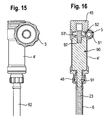
- the upper portion of a further embodiment of the tool is shown in Figs. 15 and 16 .
- the tool differs from the tool of the previous embodiment in that a preset torque adapter 90 is provided which limits the applicable torque to a specific predefined value.
- the preset torque adapter 90 is arranged in a housing 4' which can be releasably connected to the main shaft portion 23 of the driven shaft.
- the preset torque adapter 90 has a shaft portion 91 which can be coupled to the main shaft portion 23 to transfer the torque.
- the preset torque adapter further has recess 92 on the side opposite to the shaft portion 91 in which a shaft 53' engages which is fixidly connected to the worm wheel 52 of the gear unit 5.
- the recess 92 may be square recess, hexagon recess or any other recess by means of which torque can be transferred from the shaft portion 53' to the torque adapter 90.
- the torque adapter 90 has in its interior a clutch mechanism (not shown) which has a defined release torque.
- the clutch mechanism can be slipping clutch. If the applied torque exceeds the predefmed torque the torque is no longer transferred from the shaft portion 53' via the torque adapter to the main shaft portion 23.
- the housing 4' also contains the gear unit 5. It may be closed by a closure 45 with our without an additional handle. Further, the housing 4' can be connected to the counter-holding portion 6 via a screw or a press-fit or any other connection 46. The whole unit including the gear unit and the torque adapter can be selectively connected instead of the housing with the gear unit and the display unit according to the previous embodiment.
- the gear unit needs not to be a worm drive, it could also be realized by a planetary gear unit, in particular with coaxial drive shaft and driven shaft. Any other reduction gear unit may be used also.
- the counter-holding portion and the tip portion may be exchanged such that the counter holding portion is at the center and the tip portion of the screw driver is surrounding it.
- the counter-holding portion and the tip portion can be adapted in their shape to various shapes of receiving portions and locking elements.
Landscapes
- Health & Medical Sciences (AREA)
- Orthopedic Medicine & Surgery (AREA)
- Neurology (AREA)
- Life Sciences & Earth Sciences (AREA)
- Surgery (AREA)
- Heart & Thoracic Surgery (AREA)
- Engineering & Computer Science (AREA)
- Biomedical Technology (AREA)
- Nuclear Medicine, Radiotherapy & Molecular Imaging (AREA)
- Medical Informatics (AREA)
- Molecular Biology (AREA)
- Animal Behavior & Ethology (AREA)
- General Health & Medical Sciences (AREA)
- Public Health (AREA)
- Veterinary Medicine (AREA)
- Surgical Instruments (AREA)
- Dental Prosthetics (AREA)
Abstract
Description
- The invention relates to a tool for use with a bone anchor, wherein the bone anchor has an anchoring section and a receiving part for receiving a rod to be connected to the anchoring section and a locking element. The tool is particularly applicable in spinal surgery, for example for the fixation of a rod to pedicle screws.
- A known
tool 100 is shown inFig. 17 and 18 in connection withpolyaxial screws rod 103. Thetool 100 comprises acounter-holding portion 104 with ahandle 105 and ascrew driver portion 106 which is rotatable with respect to thecounter-holding portion 104 and which also comprises ahandle 107. Thescrew driver portion 106 has a tip portion (not shown) which engages alocking screw 108 of the polyaxial screw for fixation of therod 103 within thereceiving part 109. Thecounter-holding portion 104 engages thereceiving part 109 and holds the receiving part during tightening of thelocking screw 108. The tightening torque which is necessary for finally tightening thelocking screw 108 typically is in the range of approximately 7 to 15 Nm. The counter-holding portion is advantageous in particular for counter-holding such high tightening torques. However, since the counter-holding portion acts at least partially onto the rod, the known tool is not suitable for flexible rods, for example for rods made of an elastomer material such as PCU, since the loads would lead to deformations which may damage the rod. Further, the sensitive handling with two hands is difficult when applying high tightening torques. - A tool which has a counter-holding portion which engages the receiving portion of a bone anchor in a positive fit manner is known from
EP 1 726 264 . - It is an object of the invention to provide a tool for use with a bone anchor of the above described type where loads acting onto the bone anchor and therefore onto the bone are reduced and which allows for a facilitated handling.
- The object is solved by a tool according to claim 1. Further developments are given in the dependent claims.
- The tool has the advantage that the tightening torque which has to be applied manually by the surgeon is considerably reduced. Therefore, the manually applied fastening torque is small and tightening of the locking screw can be performed smoothly.
- The flow of forces is restricted to the locking element and the tool which implies that the force applied during final tightening is transferred directly from the locking element through the receiving member to the counter holding portion. This results in an unloaded rod element. In addition, the tightening load is not transferred into the bone by the bone anchor.
- The tip portion of the screw driver portion of the tool may be exchangeable. Therefore, a suitable tip portion can be selected and the tool can be used for different kinds of locking elements.
- The applied fastening torque may be limited by either observing a display indicating the applied torque and manually stopping the application of torque or by using a preset torque adapter which can be mounted together with the gear unit.
- Further features and advantages of the invention will become apparent by the description of embodiments by means of the accompanying drawings.
- In the drawings:
- Fig. 1
- shows a perspective view of an embodiment of the tool.
- Fig. 2
- shows an enlarged portion of
Fig. 1 . - Fig. 3
- shows a perspective exploded view of the tool.
- Fig. 4
- shows an enlarged portion of
Fig. 3 with arrows indicating the torque flow. - Fig. 5
- shows a further enlarged portion of
Fig. 3 with arrows showing the torque flow. - Fig. 6
- shows a sectional view of the lower portion of the driven shaft of the tool.
- Fig. 7
- shows a side view of the lower portion of the driven shaft according to
Fig. 6 - Fig. 8
- shows a sectional view of the lower-portion of the counter-holding por- tion of the tool.
- Fig. 9
- shows a side view of the counter-holding portion according to
Fig. 8 . - Fig. 10
- shows an enlarged perspective view of the upper portion of the tool.
- Fig. 11
- shows an exploded perspective view of the upper portion of the tool in- cluding the drive shaft.
- Fig. 12
- shows a plan view of the tool.
- Fig. 13
- shows a sectional view of the upper portion of the tool.
- Fig. 14a)-d)
- shows steps of assembling and applying the tool.
- Fig. 15
- shows a schematic side view of the upper portion of a further embodi- ment of the tool.
- Fig. 16
- shows a schematic sectional view of the further embodiment shown in
Fig. 15 . - Fig. 17
- shows a perspective view of a known tool.
- Fig. 18
- shows an enlarged portion of
Fig. 16 . - With reference to
Fig. 1 to 5 the tool according to one embodiment comprises a screw driver portion which includes a drive shaft 1 as schematically shown by the dashed live inFig. 1 and a drivenshaft 2 as shown inFig. 3 . The drive shaft 1 has ahandle 3 at its free end projecting outside ahousing 4. The drive shaft 1 and the drivenshaft 2 enclose an angle of 90° and are connected by areduction gear unit 5 which will be explained more in detail below. - The tool further comprises a
counter-holding portion 6 which is fixedly connected to thehousing 4 so that thedrive shaft 2 is rotatable with respect to thecounter-holding portion 6. At its free end opposite to thecounter-holding portion 6 thehousing 4 comprises ahandle 7 for holding the tool. - The tool further has a
display member 8 which may includevisual marks 9 for indicating the applied torque. The drivenshaft 2 has, as can be seen inFig. 3, 4 ,6 and 7 atip portion 20 with anengagement portion 21 for engagement with a locking element of a bone anchor. Such a locking element can be, for example, a set screw 108 (shown inFig. 16 ) of a receivingpart 109 of a polyaxial bone screw. Theengagement portion 21 can have a hexagon shape or a flathead, crosshead, square, hexsocket or torx shape or any other shape adapted to the respective engagement portion of the locking element. The tip portion is connected via aplug connection member 22 to amain shaft portion 23 of the drivenshaft 2. Themain shaft portion 23 has at its end facing the tip portion 20 asection 24 with an enlarged outer diameter and a recess for inserting theplug connection member 22. The tip portion has at its end facing the main shaft portion a recess for inserting a portion of theplug connection member 22. Theplug connection member 22 can have aresilient portion 25 which allows the releasable holding of thetip portion 20 in themain shaft portion 23. Further, thetip portion 20 and themain shaft portion 23 are connected in a positive fit manner, such as, for example, shown inFig. 7 by means of circumferentially projectingportions 26 which engage in circumferentially arrangedrecesses 27 at the corresponding other part, respectively. - A plurality of
tip portions 20 may be provided withdifferent engagement portions 21 which can be interchangeably connected to themain shaft portion 23. By means of the plug connection the exchange of the tip portion can be easily made by hand. At its end facing thegear unit 5 themain shaft portion 23 comprises anengagement portion 28 to be connected with thegear unit 5. - The drive shaft 1 and the reduction gear unit are now explained with particular reference to
Fig. 10 to 13 . In the embodiment shown thegear unit 5 includes a worm drive having aworm 51 connected to the drive shaft 1 and aworm wheel 52. Theworm wheel 52 also is provided with anengagement portion 53 to be engaged with theengagement portion 28 of themain shaft portion 23. The gear transmission ratio is for the application in spinal surgery around 3:1 or 10:1. The worm drive is advantageous to transmit higher torques. A common advantage of a worm drive is that the direction of transmission from the drive shaft to the driven shaft is not reversible. In surgery this has the advantage that the final tightening of the locking element can be performed exactly. - As shown in
Fig. 3 and6 to 7 , thedisplay member 8 comprises atube portion 81 which is fixed at its lower end to themain shaft portion 23 of the drivenshaft 2 so that it rotates with the drivenshaft 2. At its end facing away from thetip portion 20 thedisplay member 8 comprises a lower ring-shapedportion 82 with an enlarged diameter which carries a firstvisual mark 9a at its outer side. Thevisual mark 9a can be of any type including bars, engravings etc. It serves for indicating a predefined tightening torque. Thedisplay member 8 further comprises an upper ring-shapedportion 83 which is connected to theworm wheel 52 and therefore to themain shaft portion 23. The lower ring-shapedportion 82 and the upper ring shaped portion are rotatable against each other. Between the two ring-shaped portions, a ring shaped plate member for facilitating gliding may be provided. The upper and lower ring-shaped portions have secondvisual marks 9b which indicate zero position. - As can be seen in
Fig. 10 and13 , thehousing 4 comprises arecess 41 to allow inspection of the visual marks indicating the applied torque. - The
handle 7 may be fixedly attached to thehousing 4, for example by screwing as shown inFig. 13 . Thehousing 4 further has on its end opposite to the handle 7 a projection with fixation means, for example of the type of a thread, to connect thehousing 4 to thecounter-holding portion 6. Thecounter-holding portion 6 has on its end facing the housing connection means 61 for connecting it fixedly to thehousing 4. Thecounter-holding portion 6 further includes amain tube portion 62 shown inFig. 3 the diameter of which is such that the drivenshaft 2 and thetube portion 81 can be arranged and freely rotate therein. Further, the counter-holding portion comprises anend section 63 as shown inFig. 3 and 5 which is hollow so that thetip portion 20 extends through theend section 63. Theend section 63 has at its free end anengagement portion 64 engaging the receivingpart 109 of the bone anchor. Theengagement section 64 has a square or rectangular inner contour which is adapted to the outer contour of the receivingportion 109. In the embodiment shown the receivingportion 109 has two opposed flatouter surfaces 110 as shown for example inFig. 5 and theengagement section 64 has corresponding innerflat surfaces 65 as shown inFigs. 8 and 9 . In addition, theengagement portion 64 has on the other two sides tworecesses 66 where therod 103 can be guided through. Theend section 63 further has on the side which includes the flat surfaces tworecesses 67 which allow visualisation of the insertedtip portion 20. - In the embodiment shown, the end section is fixedly connected to the
end tube portion 62. However, it can also be releasably attached thereto so as to allow fixation ofdifferent end section 63 withengagement portion 64 adapted to the shape and size of the receiving part. Hence, theengagement portion 64 can have any shape which provides for a positive fit connection with the receivingpart 109 without acting onto therod 103. - Use of the tool is now explained with reference to
Fig. 14a ) to d).Fig. 14a ) schematically shows bone anchor which is in this example apolyaxial bone screw 101 comprising a receivingpart 109 and setscrew 108 for fixation of the rod (not shown) in the receiving part. Thebone anchor 101 is inserted into the bone, then therod 103 and thereafter theset screw 108 is inserted. Then, thecounter-holding portion 6 is fixed with theengagement portion 64 at the receiving part as shown inFig. 14b ). Thereafter, as shown inFig. 14c ) the driven shaft including thetip portion 20 is inserted. Next, as shown inFig. 14d ) thehousing 4 with the reduction gear unit and the handles is mounted. In this condition, by rotating the drive shaft by means of thehandle 3 the set screw is screwed in. When theset screw 108 abuts the rod and is blocked thereby and the drive shaft 1 is further rotated, themain shaft portion 23 of the drivenshaft 2 becomes twisted by the torque which is introduced by theworm wheel 25 via theengagement portions portion 83 which is fixedly connected to the upper end of themain shaft portion 23 is rotated by theworm wheel 52 as long as thehandle 3 is rotated by the surgeon. The lower ring-shapedportion 82 is connected with the lower end of the main shaft portion via thetube portion 81. Thus, the ring-shapedportion 82 is not rotated any more when theset screw 108 is blocked. Hence, the upper ring-shapedportion 83 rotates with respect to the lower ring-shapedportion 82 while the main shaft portion is twisted. By rotating thehandle 3 until the uppervisual mark 9b is aligned with the lowervisual mark 9a a predefined tightening torque is applied. Because of the gear unit, final tightening of the set screw is possible with low tightening torque to be manually applied.
The tool may be preassembled or assembled before or during surgery. - The
visual mark 9a can be applied when calibrating the tool. - The angle of 90° between drive shaft and driven shaft provides a convenient handling.
- As shown in
Fig. 4 and 5 the torque flow is such that the torque is transmitted from the driven shaft to the set screw and are redirected by theend section 63 of the counter-holding portion. Therefore, no forces are conducted via the rod back to the receiving portion which could loosen the anchoring section in the bone. - The upper portion of a further embodiment of the tool is shown in
Figs. 15 and 16 . The tool differs from the tool of the previous embodiment in that apreset torque adapter 90 is provided which limits the applicable torque to a specific predefined value. Thepreset torque adapter 90 is arranged in a housing 4' which can be releasably connected to themain shaft portion 23 of the driven shaft. Thepreset torque adapter 90 has ashaft portion 91 which can be coupled to themain shaft portion 23 to transfer the torque. The preset torque adapter further hasrecess 92 on the side opposite to theshaft portion 91 in which a shaft 53' engages which is fixidly connected to theworm wheel 52 of thegear unit 5. Therecess 92 may be square recess, hexagon recess or any other recess by means of which torque can be transferred from the shaft portion 53' to thetorque adapter 90. Thetorque adapter 90 has in its interior a clutch mechanism (not shown) which has a defined release torque. For example, the clutch mechanism can be slipping clutch. If the applied torque exceeds the predefmed torque the torque is no longer transferred from the shaft portion 53' via the torque adapter to themain shaft portion 23. - As shown in the Figures, the housing 4' also contains the
gear unit 5. It may be closed by aclosure 45 with our without an additional handle. Further, the housing 4' can be connected to thecounter-holding portion 6 via a screw or a press-fit or anyother connection 46. The whole unit including the gear unit and the torque adapter can be selectively connected instead of the housing with the gear unit and the display unit according to the previous embodiment. - Various modifications of the tool are conceivable. The gear unit needs not to be a worm drive, it could also be realized by a planetary gear unit, in particular with coaxial drive shaft and driven shaft. Any other reduction gear unit may be used also.
- The counter-holding portion and the tip portion may be exchanged such that the counter holding portion is at the center and the tip portion of the screw driver is surrounding it.
- The counter-holding portion and the tip portion can be adapted in their shape to various shapes of receiving portions and locking elements.
Claims (16)
- Tool for use with a bone anchor,
the tool comprising
a tip portion (20) for engaging a locking element (108) of the bone anchor,
a mechanism (1, 2) to apply torque to the tip portion (20),
a counter-holding portion (6), wherein the tip portion (20) is rotatable with respect to the counter holding portion (6),
characterized in that the mechanism to apply torque comprises a gear unit (5). - The tool of claim 1, wherein the gear unit (5) is a reduction gear unit.
- The tool of claim 2, wherein the gear reduction is in the range of approximately 3:1 to 10:1.
- The tool of one of claims 1 to 3, wherein the gear unit (5) comprises a bevel gear.
- The tool of one of claims 1 to 4, wherein gear unit (5) comprises a worm drive.
- The tool of one of claims 1 to 3, wherein the gear unit comprises a planetary drive.
- The tool of one of claims 1 to 6, wherein the tip portion (20) is releasably connected to a driven shaft of the gear unit (5).
- The tool of claim 7, wherein a plurality of tip portions (20) is provided which can be interchangeably connected to the driven shaft.
- The tool of one of claims 1 to 8, wherein the drive shaft (1) of the gear unit (5) comprises a handle (3).
- The tool of one of claims 1 to 9, wherein the counter-holding portion comprises an engagement portion (64) for engagement with the receiving part (109) which is constructed so as to provide a positive fit connection.
- The tool of Claim 10, wherein the engagement portion (64) has two opposite flat surfaces (65).
- The tool of one of claims 1 to 11, further comprising a display member (8) for indicating the value of the applied torque.
- The tool of claim 12, wherein the mechanism (2) comprises a twistable element (23) and the display member (8) indicates a twisting thereof.
- The tool of claim 13, wherein display member (8) comprises a first portion (82), which is connected to a first end of the twistable element (23) and a second portion (83) which is connected to a second end of the twistable element and wherein the first portion (82) and the second portion (83) are rotatable against each other when the twistable element (23) is twisted.
- The tool of one of claims 1 to 11, wherein the mechanism (2) comprises a preset torque adapter which can be selectively connected to the tip portion (20).
- A kit with a bone anchor comprising an anchoring section to be anchored in the bone and a receiving part (109) for receiving a rod (103) and a locking element (108) cooperating with the receiving part and a tool according to one of claims 1 to 15.
Priority Applications (11)
| Application Number | Priority Date | Filing Date | Title |
|---|---|---|---|
| ES09005130T ES2393583T3 (en) | 2009-04-07 | 2009-04-07 | Usable tool with a bone anchor, particularly for vertebral surgery |
| ES11155454.9T ES2468890T3 (en) | 2009-04-07 | 2009-04-07 | Usable tool with a bone anchor, particularly for vertebral surgery |
| EP11155459A EP2324787A1 (en) | 2009-04-07 | 2009-04-07 | Tool for use with a bone anchor, in particular for spinal surgery |
| EP09005130A EP2238937B1 (en) | 2009-04-07 | 2009-04-07 | Tool for use with a bone anchor, in particular for spinal surgery |
| EP11155454.9A EP2335629B1 (en) | 2009-04-07 | 2009-04-07 | Tool for use with a bone anchor, in particular for spinal surgery |
| KR1020100029841A KR101501272B1 (en) | 2009-04-07 | 2010-04-01 | Tool for use with a bone anchor, in particular for spinal surgery |
| JP2010086298A JP5610820B2 (en) | 2009-04-07 | 2010-04-02 | Tools for use with bone anchors |
| TW099110259A TWI527556B (en) | 2009-04-07 | 2010-04-02 | Tool for use with a bone anchor, in particular for spinal surgery |
| CN201010156676.1A CN101856263B (en) | 2009-04-07 | 2010-04-06 | Tool for use with bone anchor, in particular for spinal surgery |
| US12/755,360 US9149308B2 (en) | 2009-04-07 | 2010-04-06 | Tool for use with a bone anchor, in particular for spinal surgery |
| US13/612,283 US20130066386A1 (en) | 2009-04-07 | 2012-09-12 | Tool for use with a bone anchor, in particular for spinal surgery |
Applications Claiming Priority (1)
| Application Number | Priority Date | Filing Date | Title |
|---|---|---|---|
| EP09005130A EP2238937B1 (en) | 2009-04-07 | 2009-04-07 | Tool for use with a bone anchor, in particular for spinal surgery |
Related Child Applications (3)
| Application Number | Title | Priority Date | Filing Date |
|---|---|---|---|
| EP11155454.9A Division-Into EP2335629B1 (en) | 2009-04-07 | 2009-04-07 | Tool for use with a bone anchor, in particular for spinal surgery |
| EP11155454.9A Division EP2335629B1 (en) | 2009-04-07 | 2009-04-07 | Tool for use with a bone anchor, in particular for spinal surgery |
| EP11155459A Division-Into EP2324787A1 (en) | 2009-04-07 | 2009-04-07 | Tool for use with a bone anchor, in particular for spinal surgery |
Publications (2)
| Publication Number | Publication Date |
|---|---|
| EP2238937A1 true EP2238937A1 (en) | 2010-10-13 |
| EP2238937B1 EP2238937B1 (en) | 2012-08-22 |
Family
ID=41073439
Family Applications (3)
| Application Number | Title | Priority Date | Filing Date |
|---|---|---|---|
| EP11155459A Withdrawn EP2324787A1 (en) | 2009-04-07 | 2009-04-07 | Tool for use with a bone anchor, in particular for spinal surgery |
| EP11155454.9A Not-in-force EP2335629B1 (en) | 2009-04-07 | 2009-04-07 | Tool for use with a bone anchor, in particular for spinal surgery |
| EP09005130A Not-in-force EP2238937B1 (en) | 2009-04-07 | 2009-04-07 | Tool for use with a bone anchor, in particular for spinal surgery |
Family Applications Before (2)
| Application Number | Title | Priority Date | Filing Date |
|---|---|---|---|
| EP11155459A Withdrawn EP2324787A1 (en) | 2009-04-07 | 2009-04-07 | Tool for use with a bone anchor, in particular for spinal surgery |
| EP11155454.9A Not-in-force EP2335629B1 (en) | 2009-04-07 | 2009-04-07 | Tool for use with a bone anchor, in particular for spinal surgery |
Country Status (7)
| Country | Link |
|---|---|
| US (2) | US9149308B2 (en) |
| EP (3) | EP2324787A1 (en) |
| JP (1) | JP5610820B2 (en) |
| KR (1) | KR101501272B1 (en) |
| CN (1) | CN101856263B (en) |
| ES (2) | ES2393583T3 (en) |
| TW (1) | TWI527556B (en) |
Cited By (2)
| Publication number | Priority date | Publication date | Assignee | Title |
|---|---|---|---|---|
| WO2015155658A1 (en) * | 2014-04-08 | 2015-10-15 | Medacta International Sa | Fixing device for a surgical anchor member |
| CN111200984A (en) * | 2017-06-27 | 2020-05-26 | 美多斯国际有限公司 | Spinal screw insertion device and method |
Families Citing this family (36)
| Publication number | Priority date | Publication date | Assignee | Title |
|---|---|---|---|---|
| US20160242816A9 (en) | 2001-05-09 | 2016-08-25 | Roger P. Jackson | Dynamic spinal stabilization assembly with elastic bumpers and locking limited travel closure mechanisms |
| US7862587B2 (en) | 2004-02-27 | 2011-01-04 | Jackson Roger P | Dynamic stabilization assemblies, tool set and method |
| US11241261B2 (en) | 2005-09-30 | 2022-02-08 | Roger P Jackson | Apparatus and method for soft spinal stabilization using a tensionable cord and releasable end structure |
| US7901437B2 (en) | 2007-01-26 | 2011-03-08 | Jackson Roger P | Dynamic stabilization member with molded connection |
| US11224463B2 (en) | 2007-01-18 | 2022-01-18 | Roger P. Jackson | Dynamic stabilization connecting member with pre-tensioned flexible core member |
| US10383660B2 (en) | 2007-05-01 | 2019-08-20 | Roger P. Jackson | Soft stabilization assemblies with pretensioned cords |
| US8439922B1 (en) | 2008-02-06 | 2013-05-14 | NiVasive, Inc. | Systems and methods for holding and implanting bone anchors |
| EP2442739A1 (en) * | 2008-08-01 | 2012-04-25 | Jackson, Roger P. | Longitudinal connecting member with sleeved tensioned cords |
| EP2324787A1 (en) * | 2009-04-07 | 2011-05-25 | BIEDERMANN MOTECH GmbH | Tool for use with a bone anchor, in particular for spinal surgery |
| US20150105831A1 (en) * | 2009-10-09 | 2015-04-16 | Synthes Usa, Lla | Tightening device for spine surgery |
| US8545505B2 (en) | 2010-01-15 | 2013-10-01 | Pioneer Surgical Technology, Inc. | Low friction rod persuader |
| EP2613719A1 (en) | 2010-09-08 | 2013-07-17 | Roger P. Jackson | Dynamic stabilization members with elastic and inelastic sections |
| US8696511B2 (en) * | 2010-10-29 | 2014-04-15 | Warsaw Orthopedic, Inc. | Surgical instrument with plantary gear system |
| US9198698B1 (en) | 2011-02-10 | 2015-12-01 | Nuvasive, Inc. | Minimally invasive spinal fixation system and related methods |
| GB2497782A (en) | 2011-12-20 | 2013-06-26 | Vincent Lefauconnier | Bone fixation device |
| US9554820B2 (en) | 2012-06-01 | 2017-01-31 | Covidien Lp | Ultrasonic surgical instrument |
| US9402673B2 (en) * | 2012-09-28 | 2016-08-02 | DePuy Synthes Products, Inc. | Devices and methods for breaking and retaining surgical reduction tabs |
| WO2014085870A1 (en) | 2012-12-08 | 2014-06-12 | Kevin Seex | Surgical tool |
| US9486256B1 (en) | 2013-03-15 | 2016-11-08 | Nuvasive, Inc. | Rod reduction assemblies and related methods |
| US10136927B1 (en) | 2013-03-15 | 2018-11-27 | Nuvasive, Inc. | Rod reduction assemblies and related methods |
| DE102014109200A1 (en) * | 2014-07-01 | 2016-01-07 | Aesculap Ag | Medical screwdriver, shaft for the medical screwdriver and method for introducing pedicle screws |
| WO2016044843A1 (en) * | 2014-09-19 | 2016-03-24 | In Queue Innovations, Llc | Fusion systems and methods of assembly and use |
| US9987066B2 (en) | 2014-12-15 | 2018-06-05 | Medos International Sarl | Bone anchor driver and methods |
| US11278325B2 (en) | 2015-03-11 | 2022-03-22 | Warsaw Orthopedic, Inc. | Surgical instrument and method |
| US11672575B2 (en) | 2015-03-11 | 2023-06-13 | Warsaw Orthopedic, Inc. | Surgical instrument and method |
| EP3092962B1 (en) * | 2015-05-12 | 2017-10-04 | Biedermann Technologies GmbH & Co. KG | Instrument for use with a polyaxial bone anchoring device and system including the instrument and a polyaxial bone anchoring device |
| US9974577B1 (en) | 2015-05-21 | 2018-05-22 | Nuvasive, Inc. | Methods and instruments for performing leveraged reduction during single position spine surgery |
| CN105232124A (en) * | 2015-10-13 | 2016-01-13 | 广州聚生生物科技有限公司 | Bare-handed nail implantation external fixation system |
| CN106002428A (en) * | 2016-06-20 | 2016-10-12 | 昆山鸿福泰环保科技有限公司 | Novel receiving internal rod |
| US10398481B2 (en) | 2016-10-03 | 2019-09-03 | Nuvasive, Inc. | Spinal fixation system |
| CN106510834B (en) * | 2016-11-22 | 2020-05-12 | 常州华森医疗器械有限公司 | Installation tool for pedicle of vertebral arch fixing system |
| US10779866B2 (en) | 2016-12-29 | 2020-09-22 | K2M, Inc. | Rod reducer assembly |
| US10463404B2 (en) * | 2017-07-27 | 2019-11-05 | Warsaw Orthopedic, Inc. | Spinal implant system and method |
| US11051861B2 (en) | 2018-06-13 | 2021-07-06 | Nuvasive, Inc. | Rod reduction assemblies and related methods |
| US11229462B2 (en) | 2019-05-07 | 2022-01-25 | Warsaw Orthopedic, Inc. | Head assembly inserters |
| US11432852B1 (en) | 2021-03-22 | 2022-09-06 | Warsaw Orthopedic, Inc. | Screw shank based tissue retraction |
Citations (4)
| Publication number | Priority date | Publication date | Assignee | Title |
|---|---|---|---|---|
| DE8526564U1 (en) * | 1985-09-17 | 1986-03-06 | Kreidler, Eberhard, 7204 Wurmlingen | Device for driving a tool |
| EP1726264A1 (en) | 2005-05-27 | 2006-11-29 | BIEDERMANN MOTECH GmbH | Receiving part for connecting a shank of a bone anchoring element to a rod and bone anchoring device with such a receiving part |
| US7296500B1 (en) | 2005-01-15 | 2007-11-20 | Nu Vasive, Inc. | System and method for applying torque to a fastener |
| US20080200918A1 (en) | 2007-02-12 | 2008-08-21 | James Spitler | Pedicle screw driver |
Family Cites Families (37)
| Publication number | Priority date | Publication date | Assignee | Title |
|---|---|---|---|---|
| US4762031A (en) * | 1986-09-05 | 1988-08-09 | Ross Bradley | Ratchet wrenches |
| US5632748A (en) * | 1993-06-14 | 1997-05-27 | Linvatec Corporation | Endosteal anchoring device for urging a ligament against a bone surface |
| ES2121326T3 (en) * | 1994-09-27 | 1998-11-16 | Straumann Inst Ag | SURGICAL DYNAMOMETRIC KEY WITH A TURN TIME INDICATOR. |
| IL128261A0 (en) * | 1999-01-27 | 1999-11-30 | Disc O Tech Medical Tech Ltd | Expandable element |
| US6272952B1 (en) * | 2000-05-10 | 2001-08-14 | Yu-Tu Hsu | Double-reversible screwdriver and wrench combination hand tool |
| US6330845B1 (en) * | 2000-05-17 | 2001-12-18 | Bristol-Myers Squibb | Wrench for an implant |
| US6634260B1 (en) * | 2000-11-02 | 2003-10-21 | Jonathan R Smith | Anchored and screw assisted wrench tool |
| US6393949B1 (en) * | 2000-12-27 | 2002-05-28 | Yen Hsing Enterprise Co., Ltd. | Ratchet screwdriver |
| JP2003019142A (en) * | 2001-07-05 | 2003-01-21 | Robert Reed Shokai Co Ltd | Medical driver |
| DE10136129A1 (en) * | 2001-07-27 | 2003-02-20 | Biedermann Motech Gmbh | Bone screw and fastening tool for this |
| US6723043B2 (en) * | 2001-09-25 | 2004-04-20 | Sdgi Holdings, Inc. | Methods and devices for inserting and manipulating surgical instruments |
| US20030213340A1 (en) * | 2002-05-16 | 2003-11-20 | Alden Ray M. | Reverse torque drive ratchet wrench |
| US7588573B2 (en) * | 2002-09-23 | 2009-09-15 | Warsaw Orthopedic, Inc. | Expansion tool for adjustable spinal implant |
| DK2284266T3 (en) * | 2002-11-14 | 2014-01-13 | Thermo Fisher Scient Biosciences Inc | SIRNA MOLECULE MOD TP53 |
| JP3677503B2 (en) * | 2003-03-24 | 2005-08-03 | 株式会社空研 | wrench |
| AU2004245015A1 (en) * | 2003-05-30 | 2004-12-16 | Frank Nguyen | Methods and devices for transpedicular discectomy |
| US8926637B2 (en) * | 2003-06-13 | 2015-01-06 | Covidien Lp | Multiple member interconnect for surgical instrument and absorbable screw fastener |
| US7297166B2 (en) * | 2003-06-25 | 2007-11-20 | Depuy Products, Inc. | Assembly tool for modular implants and associated method |
| US20040267275A1 (en) * | 2003-06-26 | 2004-12-30 | Cournoyer John R. | Spinal implant holder and rod reduction systems and methods |
| DE10357926B3 (en) * | 2003-12-11 | 2005-09-01 | Deltacor Gmbh | Length adjustable spinal implant |
| US8152810B2 (en) * | 2004-11-23 | 2012-04-10 | Jackson Roger P | Spinal fixation tool set and method |
| US7338499B1 (en) * | 2004-09-13 | 2008-03-04 | Howmedia Osteonics Corp. | Hip arthroplasty balancing apparatus and method |
| US7691129B2 (en) * | 2004-10-27 | 2010-04-06 | Felix Brent A | Spinal stabilizing system |
| US20060229607A1 (en) * | 2005-03-16 | 2006-10-12 | Sdgi Holdings, Inc. | Systems, kits and methods for treatment of the spinal column using elongate support members |
| US7194934B2 (en) * | 2005-05-23 | 2007-03-27 | Custom Spine, Inc. | Ratcheting torque wrench |
| US20070006692A1 (en) * | 2005-07-11 | 2007-01-11 | Phan Christopher U | Torque limiting device |
| US20070149981A1 (en) * | 2005-12-09 | 2007-06-28 | Massachusetts General Hospital | Implant insertion device |
| US7644848B2 (en) | 2006-01-31 | 2010-01-12 | Ethicon Endo-Surgery, Inc. | Electronic lockouts and surgical instrument including same |
| US7464846B2 (en) * | 2006-01-31 | 2008-12-16 | Ethicon Endo-Surgery, Inc. | Surgical instrument having a removable battery |
| US7100476B1 (en) * | 2006-02-01 | 2006-09-05 | Feit Steven H | Torque wrench for dental implants |
| US20080243134A1 (en) * | 2007-03-29 | 2008-10-02 | Limberg Kurt P | Bidirectionally ratcheting surgical instrument |
| US20090024174A1 (en) * | 2007-07-17 | 2009-01-22 | Stark John G | Bone screws and particular applications to sacroiliac joint fusion |
| US8156847B2 (en) * | 2007-08-07 | 2012-04-17 | Alphatec Spine, Inc. | Undercut screw feature and driver |
| US20090112219A1 (en) * | 2007-10-31 | 2009-04-30 | Daniels David W | Taper sleeve extractor |
| US20090275993A1 (en) * | 2008-04-30 | 2009-11-05 | Phan Christopher U | Apparatus and methods for inserting facet screws |
| US20100211115A1 (en) * | 2008-12-24 | 2010-08-19 | Jeff Tyber | Compression screw assembly, an orthopedic fixation system including a compression screw assembly and method of use |
| EP2324787A1 (en) * | 2009-04-07 | 2011-05-25 | BIEDERMANN MOTECH GmbH | Tool for use with a bone anchor, in particular for spinal surgery |
-
2009
- 2009-04-07 EP EP11155459A patent/EP2324787A1/en not_active Withdrawn
- 2009-04-07 EP EP11155454.9A patent/EP2335629B1/en not_active Not-in-force
- 2009-04-07 ES ES09005130T patent/ES2393583T3/en active Active
- 2009-04-07 EP EP09005130A patent/EP2238937B1/en not_active Not-in-force
- 2009-04-07 ES ES11155454.9T patent/ES2468890T3/en active Active
-
2010
- 2010-04-01 KR KR1020100029841A patent/KR101501272B1/en active IP Right Grant
- 2010-04-02 JP JP2010086298A patent/JP5610820B2/en not_active Expired - Fee Related
- 2010-04-02 TW TW099110259A patent/TWI527556B/en not_active IP Right Cessation
- 2010-04-06 US US12/755,360 patent/US9149308B2/en active Active
- 2010-04-06 CN CN201010156676.1A patent/CN101856263B/en not_active Expired - Fee Related
-
2012
- 2012-09-12 US US13/612,283 patent/US20130066386A1/en not_active Abandoned
Patent Citations (4)
| Publication number | Priority date | Publication date | Assignee | Title |
|---|---|---|---|---|
| DE8526564U1 (en) * | 1985-09-17 | 1986-03-06 | Kreidler, Eberhard, 7204 Wurmlingen | Device for driving a tool |
| US7296500B1 (en) | 2005-01-15 | 2007-11-20 | Nu Vasive, Inc. | System and method for applying torque to a fastener |
| EP1726264A1 (en) | 2005-05-27 | 2006-11-29 | BIEDERMANN MOTECH GmbH | Receiving part for connecting a shank of a bone anchoring element to a rod and bone anchoring device with such a receiving part |
| US20080200918A1 (en) | 2007-02-12 | 2008-08-21 | James Spitler | Pedicle screw driver |
Cited By (3)
| Publication number | Priority date | Publication date | Assignee | Title |
|---|---|---|---|---|
| WO2015155658A1 (en) * | 2014-04-08 | 2015-10-15 | Medacta International Sa | Fixing device for a surgical anchor member |
| CN111200984A (en) * | 2017-06-27 | 2020-05-26 | 美多斯国际有限公司 | Spinal screw insertion device and method |
| CN111200984B (en) * | 2017-06-27 | 2023-05-05 | 美多斯国际有限公司 | Spinal screw insertion device and method |
Also Published As
| Publication number | Publication date |
|---|---|
| EP2238937B1 (en) | 2012-08-22 |
| CN101856263A (en) | 2010-10-13 |
| JP5610820B2 (en) | 2014-10-22 |
| KR20100111621A (en) | 2010-10-15 |
| ES2393583T3 (en) | 2012-12-26 |
| EP2335629B1 (en) | 2014-03-26 |
| TWI527556B (en) | 2016-04-01 |
| EP2324787A1 (en) | 2011-05-25 |
| US20130066386A1 (en) | 2013-03-14 |
| US20110004222A1 (en) | 2011-01-06 |
| JP2010240425A (en) | 2010-10-28 |
| US9149308B2 (en) | 2015-10-06 |
| CN101856263B (en) | 2014-08-20 |
| EP2335629A1 (en) | 2011-06-22 |
| KR101501272B1 (en) | 2015-03-11 |
| ES2468890T3 (en) | 2014-06-17 |
| TW201036587A (en) | 2010-10-16 |
Similar Documents
| Publication | Publication Date | Title |
|---|---|---|
| EP2335629B1 (en) | Tool for use with a bone anchor, in particular for spinal surgery | |
| EP2969395B1 (en) | Ratcheting torque wrench | |
| EP2219541B1 (en) | An instrument for placing a "polyaxial" bone screw of vertebral osteosynthesis equipment | |
| US7824428B2 (en) | System to be used with an implanting tool | |
| JP6635688B2 (en) | Medical screwdriver, method of introducing shank and pedicle screw for medical screwdriver | |
| US7572264B2 (en) | Driver instrument for use in a surgical application | |
| EP2566411B1 (en) | Ultra high torque device | |
| EP2948093B1 (en) | In-line disposable torque limiting device suitable for power drive | |
| EP2675595B1 (en) | International application for enhanced high torque device | |
| US20080016990A1 (en) | Semi automatic disposable torque limiting device and method | |
| US20100107829A1 (en) | Torque limiting driver | |
| AU2003202403A1 (en) | Screw comprising an integrated screwdriver | |
| ES2446541T3 (en) | Torque wrench, in particular for the medical field | |
| EP1955667A1 (en) | Global nail screw retaining screwdriver | |
| US10925654B2 (en) | Apparatus, system, and method for crimping a cable for bone fixation | |
| US20170128116A1 (en) | Torque limiting devices and methods of use | |
| TWI742925B (en) | Tool for bone implant | |
| EP2948078B1 (en) | Fortified plastic disposable torque devices | |
| US20220125489A1 (en) | System for Tightening an Orthopedic Set Screw at Two Different Torque Levels | |
| US20230356373A1 (en) | Counter-torque driver tool | |
| WO2021237328A1 (en) | Dental and orthopedic insertion tool |
Legal Events
| Date | Code | Title | Description |
|---|---|---|---|
| PUAI | Public reference made under article 153(3) epc to a published international application that has entered the european phase |
Free format text: ORIGINAL CODE: 0009012 |
|
| 17P | Request for examination filed |
Effective date: 20100521 |
|
| AK | Designated contracting states |
Kind code of ref document: A1 Designated state(s): AT BE BG CH CY CZ DE DK EE ES FI FR GB GR HR HU IE IS IT LI LT LU LV MC MK MT NL NO PL PT RO SE SI SK TR |
|
| AX | Request for extension of the european patent |
Extension state: AL BA RS |
|
| GRAP | Despatch of communication of intention to grant a patent |
Free format text: ORIGINAL CODE: EPIDOSNIGR1 |
|
| RIC1 | Information provided on ipc code assigned before grant |
Ipc: A61B 17/88 20060101AFI20120228BHEP Ipc: A61B 19/00 20060101ALN20120228BHEP |
|
| RAP1 | Party data changed (applicant data changed or rights of an application transferred) |
Owner name: BIEDERMANN TECHNOLOGIES GMBH & CO. KG |
|
| GRAS | Grant fee paid |
Free format text: ORIGINAL CODE: EPIDOSNIGR3 |
|
| GRAA | (expected) grant |
Free format text: ORIGINAL CODE: 0009210 |
|
| AK | Designated contracting states |
Kind code of ref document: B1 Designated state(s): AT BE BG CH CY CZ DE DK EE ES FI FR GB GR HR HU IE IS IT LI LT LU LV MC MK MT NL NO PL PT RO SE SI SK TR |
|
| REG | Reference to a national code |
Ref country code: GB Ref legal event code: FG4D |
|
| REG | Reference to a national code |
Ref country code: CH Ref legal event code: NV Representative=s name: NOVAGRAAF INTERNATIONAL SA Ref country code: CH Ref legal event code: EP |
|
| REG | Reference to a national code |
Ref country code: IE Ref legal event code: FG4D |
|
| REG | Reference to a national code |
Ref country code: AT Ref legal event code: REF Ref document number: 571490 Country of ref document: AT Kind code of ref document: T Effective date: 20120915 |
|
| REG | Reference to a national code |
Ref country code: DE Ref legal event code: R096 Ref document number: 602009009125 Country of ref document: DE Effective date: 20121018 |
|
| REG | Reference to a national code |
Ref country code: ES Ref legal event code: FG2A Ref document number: 2393583 Country of ref document: ES Kind code of ref document: T3 Effective date: 20121226 |
|
| REG | Reference to a national code |
Ref country code: NL Ref legal event code: VDEP Effective date: 20120822 |
|
| REG | Reference to a national code |
Ref country code: AT Ref legal event code: MK05 Ref document number: 571490 Country of ref document: AT Kind code of ref document: T Effective date: 20120822 |
|
| REG | Reference to a national code |
Ref country code: LT Ref legal event code: MG4D Effective date: 20120822 |
|
| PG25 | Lapsed in a contracting state [announced via postgrant information from national office to epo] |
Ref country code: HR Free format text: LAPSE BECAUSE OF FAILURE TO SUBMIT A TRANSLATION OF THE DESCRIPTION OR TO PAY THE FEE WITHIN THE PRESCRIBED TIME-LIMIT Effective date: 20120822 Ref country code: IS Free format text: LAPSE BECAUSE OF FAILURE TO SUBMIT A TRANSLATION OF THE DESCRIPTION OR TO PAY THE FEE WITHIN THE PRESCRIBED TIME-LIMIT Effective date: 20121222 Ref country code: CY Free format text: LAPSE BECAUSE OF FAILURE TO SUBMIT A TRANSLATION OF THE DESCRIPTION OR TO PAY THE FEE WITHIN THE PRESCRIBED TIME-LIMIT Effective date: 20120822 Ref country code: FI Free format text: LAPSE BECAUSE OF FAILURE TO SUBMIT A TRANSLATION OF THE DESCRIPTION OR TO PAY THE FEE WITHIN THE PRESCRIBED TIME-LIMIT Effective date: 20120822 Ref country code: AT Free format text: LAPSE BECAUSE OF FAILURE TO SUBMIT A TRANSLATION OF THE DESCRIPTION OR TO PAY THE FEE WITHIN THE PRESCRIBED TIME-LIMIT Effective date: 20120822 Ref country code: NO Free format text: LAPSE BECAUSE OF FAILURE TO SUBMIT A TRANSLATION OF THE DESCRIPTION OR TO PAY THE FEE WITHIN THE PRESCRIBED TIME-LIMIT Effective date: 20121122 Ref country code: LT Free format text: LAPSE BECAUSE OF FAILURE TO SUBMIT A TRANSLATION OF THE DESCRIPTION OR TO PAY THE FEE WITHIN THE PRESCRIBED TIME-LIMIT Effective date: 20120822 |
|
| PG25 | Lapsed in a contracting state [announced via postgrant information from national office to epo] |
Ref country code: SE Free format text: LAPSE BECAUSE OF FAILURE TO SUBMIT A TRANSLATION OF THE DESCRIPTION OR TO PAY THE FEE WITHIN THE PRESCRIBED TIME-LIMIT Effective date: 20120822 Ref country code: SI Free format text: LAPSE BECAUSE OF FAILURE TO SUBMIT A TRANSLATION OF THE DESCRIPTION OR TO PAY THE FEE WITHIN THE PRESCRIBED TIME-LIMIT Effective date: 20120822 Ref country code: GR Free format text: LAPSE BECAUSE OF FAILURE TO SUBMIT A TRANSLATION OF THE DESCRIPTION OR TO PAY THE FEE WITHIN THE PRESCRIBED TIME-LIMIT Effective date: 20121123 Ref country code: LV Free format text: LAPSE BECAUSE OF FAILURE TO SUBMIT A TRANSLATION OF THE DESCRIPTION OR TO PAY THE FEE WITHIN THE PRESCRIBED TIME-LIMIT Effective date: 20120822 Ref country code: BE Free format text: LAPSE BECAUSE OF FAILURE TO SUBMIT A TRANSLATION OF THE DESCRIPTION OR TO PAY THE FEE WITHIN THE PRESCRIBED TIME-LIMIT Effective date: 20120822 Ref country code: PT Free format text: LAPSE BECAUSE OF FAILURE TO SUBMIT A TRANSLATION OF THE DESCRIPTION OR TO PAY THE FEE WITHIN THE PRESCRIBED TIME-LIMIT Effective date: 20121224 |
|
| PG25 | Lapsed in a contracting state [announced via postgrant information from national office to epo] |
Ref country code: NL Free format text: LAPSE BECAUSE OF FAILURE TO SUBMIT A TRANSLATION OF THE DESCRIPTION OR TO PAY THE FEE WITHIN THE PRESCRIBED TIME-LIMIT Effective date: 20120822 |
|
| PG25 | Lapsed in a contracting state [announced via postgrant information from national office to epo] |
Ref country code: DK Free format text: LAPSE BECAUSE OF FAILURE TO SUBMIT A TRANSLATION OF THE DESCRIPTION OR TO PAY THE FEE WITHIN THE PRESCRIBED TIME-LIMIT Effective date: 20120822 Ref country code: EE Free format text: LAPSE BECAUSE OF FAILURE TO SUBMIT A TRANSLATION OF THE DESCRIPTION OR TO PAY THE FEE WITHIN THE PRESCRIBED TIME-LIMIT Effective date: 20120822 Ref country code: RO Free format text: LAPSE BECAUSE OF FAILURE TO SUBMIT A TRANSLATION OF THE DESCRIPTION OR TO PAY THE FEE WITHIN THE PRESCRIBED TIME-LIMIT Effective date: 20120822 Ref country code: CZ Free format text: LAPSE BECAUSE OF FAILURE TO SUBMIT A TRANSLATION OF THE DESCRIPTION OR TO PAY THE FEE WITHIN THE PRESCRIBED TIME-LIMIT Effective date: 20120822 |
|
| PG25 | Lapsed in a contracting state [announced via postgrant information from national office to epo] |
Ref country code: PL Free format text: LAPSE BECAUSE OF FAILURE TO SUBMIT A TRANSLATION OF THE DESCRIPTION OR TO PAY THE FEE WITHIN THE PRESCRIBED TIME-LIMIT Effective date: 20120822 Ref country code: SK Free format text: LAPSE BECAUSE OF FAILURE TO SUBMIT A TRANSLATION OF THE DESCRIPTION OR TO PAY THE FEE WITHIN THE PRESCRIBED TIME-LIMIT Effective date: 20120822 |
|
| PLBE | No opposition filed within time limit |
Free format text: ORIGINAL CODE: 0009261 |
|
| STAA | Information on the status of an ep patent application or granted ep patent |
Free format text: STATUS: NO OPPOSITION FILED WITHIN TIME LIMIT |
|
| 26N | No opposition filed |
Effective date: 20130523 |
|
| PG25 | Lapsed in a contracting state [announced via postgrant information from national office to epo] |
Ref country code: BG Free format text: LAPSE BECAUSE OF FAILURE TO SUBMIT A TRANSLATION OF THE DESCRIPTION OR TO PAY THE FEE WITHIN THE PRESCRIBED TIME-LIMIT Effective date: 20121122 |
|
| REG | Reference to a national code |
Ref country code: DE Ref legal event code: R097 Ref document number: 602009009125 Country of ref document: DE Effective date: 20130523 |
|
| PG25 | Lapsed in a contracting state [announced via postgrant information from national office to epo] |
Ref country code: MC Free format text: LAPSE BECAUSE OF FAILURE TO SUBMIT A TRANSLATION OF THE DESCRIPTION OR TO PAY THE FEE WITHIN THE PRESCRIBED TIME-LIMIT Effective date: 20120822 |
|
| REG | Reference to a national code |
Ref country code: IE Ref legal event code: MM4A |
|
| PG25 | Lapsed in a contracting state [announced via postgrant information from national office to epo] |
Ref country code: IE Free format text: LAPSE BECAUSE OF NON-PAYMENT OF DUE FEES Effective date: 20130407 |
|
| PG25 | Lapsed in a contracting state [announced via postgrant information from national office to epo] |
Ref country code: MT Free format text: LAPSE BECAUSE OF FAILURE TO SUBMIT A TRANSLATION OF THE DESCRIPTION OR TO PAY THE FEE WITHIN THE PRESCRIBED TIME-LIMIT Effective date: 20120822 |
|
| PG25 | Lapsed in a contracting state [announced via postgrant information from national office to epo] |
Ref country code: TR Free format text: LAPSE BECAUSE OF FAILURE TO SUBMIT A TRANSLATION OF THE DESCRIPTION OR TO PAY THE FEE WITHIN THE PRESCRIBED TIME-LIMIT Effective date: 20120822 |
|
| PG25 | Lapsed in a contracting state [announced via postgrant information from national office to epo] |
Ref country code: HU Free format text: LAPSE BECAUSE OF FAILURE TO SUBMIT A TRANSLATION OF THE DESCRIPTION OR TO PAY THE FEE WITHIN THE PRESCRIBED TIME-LIMIT; INVALID AB INITIO Effective date: 20090407 Ref country code: MK Free format text: LAPSE BECAUSE OF FAILURE TO SUBMIT A TRANSLATION OF THE DESCRIPTION OR TO PAY THE FEE WITHIN THE PRESCRIBED TIME-LIMIT Effective date: 20120822 Ref country code: LU Free format text: LAPSE BECAUSE OF NON-PAYMENT OF DUE FEES Effective date: 20130407 |
|
| REG | Reference to a national code |
Ref country code: FR Ref legal event code: PLFP Year of fee payment: 8 |
|
| REG | Reference to a national code |
Ref country code: FR Ref legal event code: PLFP Year of fee payment: 9 |
|
| REG | Reference to a national code |
Ref country code: FR Ref legal event code: PLFP Year of fee payment: 10 |
|
| PGFP | Annual fee paid to national office [announced via postgrant information from national office to epo] |
Ref country code: IT Payment date: 20220427 Year of fee payment: 14 Ref country code: GB Payment date: 20220425 Year of fee payment: 14 Ref country code: FR Payment date: 20220421 Year of fee payment: 14 Ref country code: ES Payment date: 20220518 Year of fee payment: 14 Ref country code: DE Payment date: 20220427 Year of fee payment: 14 |
|
| PGFP | Annual fee paid to national office [announced via postgrant information from national office to epo] |
Ref country code: CH Payment date: 20220425 Year of fee payment: 14 |
|
| P01 | Opt-out of the competence of the unified patent court (upc) registered |
Effective date: 20230525 |
|
| REG | Reference to a national code |
Ref country code: DE Ref legal event code: R119 Ref document number: 602009009125 Country of ref document: DE |
|
| REG | Reference to a national code |
Ref country code: CH Ref legal event code: PL |
|
| GBPC | Gb: european patent ceased through non-payment of renewal fee |
Effective date: 20230407 |
|
| PG25 | Lapsed in a contracting state [announced via postgrant information from national office to epo] |
Ref country code: GB Free format text: LAPSE BECAUSE OF NON-PAYMENT OF DUE FEES Effective date: 20230407 |
|
| PG25 | Lapsed in a contracting state [announced via postgrant information from national office to epo] |
Ref country code: LI Free format text: LAPSE BECAUSE OF NON-PAYMENT OF DUE FEES Effective date: 20230430 Ref country code: GB Free format text: LAPSE BECAUSE OF NON-PAYMENT OF DUE FEES Effective date: 20230407 Ref country code: FR Free format text: LAPSE BECAUSE OF NON-PAYMENT OF DUE FEES Effective date: 20230430 Ref country code: DE Free format text: LAPSE BECAUSE OF NON-PAYMENT OF DUE FEES Effective date: 20231103 Ref country code: CH Free format text: LAPSE BECAUSE OF NON-PAYMENT OF DUE FEES Effective date: 20230430 |
|
| PG25 | Lapsed in a contracting state [announced via postgrant information from national office to epo] |
Ref country code: IT Free format text: LAPSE BECAUSE OF NON-PAYMENT OF DUE FEES Effective date: 20230407 |
|
| REG | Reference to a national code |
Ref country code: ES Ref legal event code: FD2A Effective date: 20240528 |
|
| PG25 | Lapsed in a contracting state [announced via postgrant information from national office to epo] |
Ref country code: ES Free format text: LAPSE BECAUSE OF NON-PAYMENT OF DUE FEES Effective date: 20230408 |
|
| PG25 | Lapsed in a contracting state [announced via postgrant information from national office to epo] |
Ref country code: ES Free format text: LAPSE BECAUSE OF NON-PAYMENT OF DUE FEES Effective date: 20230408 |