EP2238818A1 - Aufsatteldrehpflug mit einer Einrichtung zur Reduzierung des Drucks - Google Patents
Aufsatteldrehpflug mit einer Einrichtung zur Reduzierung des Drucks Download PDFInfo
- Publication number
- EP2238818A1 EP2238818A1 EP10159287A EP10159287A EP2238818A1 EP 2238818 A1 EP2238818 A1 EP 2238818A1 EP 10159287 A EP10159287 A EP 10159287A EP 10159287 A EP10159287 A EP 10159287A EP 2238818 A1 EP2238818 A1 EP 2238818A1
- Authority
- EP
- European Patent Office
- Prior art keywords
- pressure
- plow
- orifice
- plow according
- cylinder
- Prior art date
- Legal status (The legal status is an assumption and is not a legal conclusion. Google has not performed a legal analysis and makes no representation as to the accuracy of the status listed.)
- Withdrawn
Links
- 230000002441 reversible effect Effects 0.000 title claims description 7
- 239000003638 chemical reducing agent Substances 0.000 claims abstract description 3
- 239000012530 fluid Substances 0.000 description 13
- 230000008878 coupling Effects 0.000 description 5
- 238000010168 coupling process Methods 0.000 description 5
- 238000005859 coupling reaction Methods 0.000 description 5
- 230000009467 reduction Effects 0.000 description 5
- 238000010586 diagram Methods 0.000 description 2
- 230000006870 function Effects 0.000 description 2
- 230000035939 shock Effects 0.000 description 2
- 230000009471 action Effects 0.000 description 1
- 230000003292 diminished effect Effects 0.000 description 1
- 230000000694 effects Effects 0.000 description 1
- 238000009434 installation Methods 0.000 description 1
- 230000004048 modification Effects 0.000 description 1
- 238000012986 modification Methods 0.000 description 1
- 238000004904 shortening Methods 0.000 description 1
- 239000002689 soil Substances 0.000 description 1
- 230000003068 static effect Effects 0.000 description 1
- 238000006467 substitution reaction Methods 0.000 description 1
- 238000011144 upstream manufacturing Methods 0.000 description 1
Images


Classifications
-
- A—HUMAN NECESSITIES
- A01—AGRICULTURE; FORESTRY; ANIMAL HUSBANDRY; HUNTING; TRAPPING; FISHING
- A01B—SOIL WORKING IN AGRICULTURE OR FORESTRY; PARTS, DETAILS, OR ACCESSORIES OF AGRICULTURAL MACHINES OR IMPLEMENTS, IN GENERAL
- A01B3/00—Ploughs with fixed plough-shares
- A01B3/46—Ploughs supported partly by tractor and partly by their own wheels
- A01B3/464—Alternating ploughs with frame rotating about a horizontal axis, e.g. turn-wrest ploughs
-
- A—HUMAN NECESSITIES
- A01—AGRICULTURE; FORESTRY; ANIMAL HUSBANDRY; HUNTING; TRAPPING; FISHING
- A01B—SOIL WORKING IN AGRICULTURE OR FORESTRY; PARTS, DETAILS, OR ACCESSORIES OF AGRICULTURAL MACHINES OR IMPLEMENTS, IN GENERAL
- A01B3/00—Ploughs with fixed plough-shares
- A01B3/36—Ploughs mounted on tractors
- A01B3/40—Alternating ploughs
- A01B3/42—Turn-wrest ploughs
Definitions
- the present invention relates to the general technical field of agricultural machinery and more particularly to a reversible plow comprising a hitching structure, a bearing structure and an actuating member for moving said bearing structure relative to said hitching structure around the hinge structure.
- a cylindrical hinge so as to bring said plow from one working position to another working position, each of the working positions being limited by a respective abutment stop.
- the carrying structure comprises a front portion connected to the coupling structure by means of a cylindrical articulation of longitudinal axis substantially parallel to the direction of advance and a rear portion supporting plow bodies.
- the supporting structure pivots about 180 ° around the longitudinal axis via a turning cylinder.
- This hydraulic cylinder is of the double-acting type and comprises a large chamber and a small chamber.
- the jack is connected on the one hand to said hitching structure by means of an upper hinge and on the other hand to said support structure by means of a lower hinge.
- the cylinder rod travels back and forth. That is to say that from a stem starting position output, the rod retracts into the cylinder under the control of the hydraulic circuit and the cylinder extends to bring the plow in its other working position.
- the circuit is supplied with fluid via the hydraulic unit of the tractor.
- the operator maintains his action on the distributor controlling the hydraulic unit throughout the reversal operation.
- a respective stop limits the pivoting of the carrier structure relative to the hitch structure.
- These stops allow adjustment of the plow plumb, that is to say, the adjustment of the perpendicularity of the plane of the props relative to the ground surface.
- Each body of plow being fixed on an age by a stanchion.
- Each of the working positions is limited by means of a corresponding adjustable plumb abutment. This is an adjustable screw stop.
- the stops are placed on the hitching structure so that the cylinder rod alternately bears on one of them.
- the jack When the carrier structure arrives in its working position after the reversal, the jack alternately hits one of the stops.
- the cylinder directly hits the abutment on which it relies to give the working position.
- the stop In this case, the stop extends on the same side of the longitudinal axis as the rod of the jack.
- This shock is caused by the unbalance of the plow and the pressure in the turning cylinder.
- the pressure in the cylinder is that of the hydraulic unit of the tractor which is of the order of 200 bar. Under the effect of repeated shocks, the hitch structure is deformed. This deformation can go as far as the breaking of the stops.
- the jack strikes the plumb abutment which extends on the other side of the longitudinal axis at the end of overturning. With such an arrangement, the forces at the abutment are reduced but it is the cylindrical articulation which is much more solicited. The hitch structure of this plow is therefore also deformed.
- the screw stop system is replaced by a memory cylinder.
- this type of hydraulic stop the inclination of the plow can be modified during plowing.
- only a symmetrical adjustment of the memory jack is possible. That is to say that a different alignment between the left-hand job and the right-hand job is not possible.
- the cost of a memory cylinder is much higher than a mechanical stop.
- the present invention aims to overcome the aforementioned drawbacks and to provide a plow with a hitch structure lighter and therefore less expensive.
- the plow has a device for reducing the pressure in said actuator without limiting the pressure between said hydraulic unit and said device.
- Said pressure reduction device makes it possible to obtain at its output a set, reduced and constant value. With said device, the impacts on the coupling structure are much less violent since the pressure in the operating member is reduced.
- the maximum pressure is equal to the set pressure of the device.
- the set pressure is well below the 200 bar of the plant hydraulic. The set pressure does not disturb the folding / unfolding of the plow if necessary.
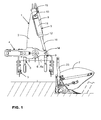
- the figure 1 represents the front part of a reversible plow.
- This reversible plow (1) has in outline a hitching structure (2) linked to a coupling system (3) at three points of a tractor (not shown), a bearing structure (4), a body operating device (5) and a circuit for controlling the operating member (5).
- the circuit is powered by a hydraulic power unit (16).
- the carrying structure (4) comprises a front part connected to the coupling structure (2) by means of a cylindrical articulation (6) of longitudinal axis (6a) substantially horizontal and directed in the direction of advance (A). and a rear portion supporting plow bodies (7).
- the upper plowing bodies and the beam with ages bearing the bodies were not represented on the figure 1 .
- the hitching structure (2) is provided with plumb abutments (8). These plumb abutments (8) are preferably in the form of adjustable screws when it comes to mechanical stop or by a memory cylinder when it comes to hydraulic stop.
- This operating member (5) consists of a double acting type hydraulic cylinder with a cylinder (9) and a piston rod (10). It has a large room (11) and a small room (12).
- the cylinder is firstly connected to the coupling structure (2) by means of an upper hinge (13) and secondly to the supporting structure (4) by means of a lower hinge (14).
- the joints (13, 14) each have a substantially horizontal axis and substantially parallel to the direction of advance (A).
- the upper articulation (13) is located above the cylindrical articulation (6) and its axis is substantially parallel to the longitudinal axis (6a) of said cylindrical articulation (6).
- the carrier structure (4) has in its front part a drive support on which is hung the rod (10) of the cylinder by means of the lower hinge (14).
- the lower hinge (14) is caused to be moved either to the left or to the right of the longitudinal axis (6a) of said cylindrical hinge (6) depending on the working position.
- the cylinder enables the carrier structure (4) to be rotated about 180 °, ie a half-turn. More specifically, when the cylinder shortens, the carrier structure (4) pivots about the longitudinal axis (6a) by about 90 °, a quarter of a turn, and then, said jack extends to pivot said carrier structure ( 4) about 90 ° further.
- the plow (1) also comprises a hydraulic block (15) for controlling in particular the operating member (5) to perform the reversal.
- the hydraulic block (15) is intended to be connected to a hydraulic unit (16) which imposes the pressure on the oil in the circuit.
- a hydraulic unit (16) which imposes the pressure on the oil in the circuit.
- it is the tractor which acts as hydraulic power station (16) while being coupled to the plow (1).
- the tractor is equipped with at least one distributor (17) with four ports and three positions. Two of the ports are connected to the hydraulic source and the other two are connected to the tank.
- This distributor (17) is manually controlled from the tractor by a lever.
- the operating member (5) is fed by the hydraulic unit (16), and in particular the tractor pump.
- the figure 2 schematically represents the hydraulic circuit of the hydraulic block (15) for controlling a reversible plow without variable working width.
- the figure 2 shows the fluid supply circuit of the large chamber (11) of the cylinder for reversal, second quarter turn.
- the hydraulic block (15) comprises a circuit with a distributor (18) with drawers that can occupy two positions and has six orifices.
- the distributor (18) has a return member (19) and control lines (20, 21, 22) for controlling it. This biasing element (19) maintains or recalls the distributor (18) in its initial position (the initial position is not shown).
- the first control line (20) communicates with a small control surface intended to act in the opposite direction of the return element (19) so as to bring the distributor (18) to its other position.
- the second control line (21) communicates with a large control surface intended to act in the opposite direction of the return element (19) so as to bring the distributor (18) to its other position.
- the third control line (22) communicates with a large driving surface intended to act in the same direction as the return element (19) so as to bring the distributor (18) to its other position.
- the two large pilot surfaces are advantageously of the same size.
- the dispenser (18) has six orifices, each of which receives a conduit that supplies the fluid.
- the distributor (18) thus communicates with the cylinder by means of a first and a second pipe (25, 26) and with the hydraulic power unit (16) by means of a third and a fourth pipe (27, 28).
- the large chamber (11) of the cylinder is connected to the first pipe (25) and the small chamber (12) is connected to the second pipe (26).
- the first control line (20) communicates with the third line (27) and the third control line (22) communicates with the fourth line (28).
- a check valve (29) located on the first conduit (25) between the large chamber (11) of the cylinder and one of the orifices of the distributor (18).
- This non-return valve (29) is controlled by the pressure prevailing in the second pipe (26) by means of an additional control line (30). It is intended to allow, when not controlled, only the passage of the fluid from the distributor (18) to the large chamber (11). When it is controlled, it allows the passage of fluid in both directions.
- This non-return valve (29) makes it possible in particular to ensure the static position of the jack during work (when no chamber (11, 12) is fed). Thus the non-return valve (29) prevents the turning cylinder from shortening.
- the fluid from the hydraulic unit (16) corresponds to the supply pressure.
- This supply pressure of the order of 200 bar therefore applies to the small and large control surfaces (20, 21) which keeps the distributor (18) in its other position (as shown).
- the turning cylinder extends, which makes it possible to pivot the supporting structure (4) by an additional quarter turn around the longitudinal axis (6a).
- the carrier structure (4) will have performed a half-turn or 180 °.
- the fluid contained in the small chamber (12) is driven out and escapes through the second pipe (26), through the distributor (18) which allows the passage of said fluid to the fourth pipe (28) to finish in the hydraulic power station (16).
- To this fluid, from the small chamber (12) of the cylinder there is a return pressure and a return flow.
- the plow (1) has a device (31) for reducing the pressure in said operating member (5) without limiting the pressure between said hydraulic unit (16) and said device (31).
- This device (31) is implanted on the first pipe (25) which feeds the large chamber (11).
- the device (31) is interposed between the non-return valve (29) and the large chamber (11) of the operating member (5).
- This device (31) makes it possible to obtain at its output a set, reduced and constant pressure value.
- the outlet pressure is determined by setting a spring adjustable by a screw-nut system.
- the device (31) is adjustable to a certain or arbitrary calibration value.
- the set pressure of the device (31) is independent of the operating pressure of the hydraulic power unit (16) of the tractor.
- the device (31) is a pressure reducer consisting of a pressure reducing valve, three direct acting channels.
- the valve is of the drawer type. Thanks to this device (31) interposed just in front of the large chamber (11) of the jack, there is no disturbance during reversal movements. With this pressure reduction device (31) when the cylinder reaches the end of its movement at the end of reversal, the cylinder bears with the reduced pressure on the corresponding abutment. The stresses on the stops as well as on the hitch structure are then well diminished.
- the device (31) is controlled by a return member (32) and a control line (33).
- This return element (32) keeps the device (31) in its initial position.
- the driving duct (33) communicates with a driving surface intended to act in the opposite direction of the return element (32) so as to bring the device (31) to its other position.
- the device (31) has three orifices (34, 35, 36).
- the first port (34) communicates with a supply line (37), the second port (35) communicates with the first line (25) and the third port (36) communicates with the return line (38).
- the device (31) is normally open and allows a flow rate of the second orifice (35).
- the inlet pressure of the device (31) at the second orifice (35) is imposed by the hydraulic unit (16) while the outlet pressure in the supply line (37) is reduced to the setting value. .
- the spool moves to limit the flow rate at the inlet of the second port (35), which regulates the pressure at the first port (34) in the line power supply (37).
- the third port (36) is drained, i.e. it is connected to the tank by means of a drain (39).
- This calibration value is stable and constant regardless of the pressure or the pressure variations in the first pipe (25). If the pressure at the first orifice (34) is greater than the setting of the device (31), the spool continues its travel to restore the excess pressure through the third orifice (36) to the reservoir. Thus, the hitch structure (2) is protected against excessive pressure variations.
- the maximum pressure that can prevail in the large chamber (11) of the cylinder is equal to the set pressure set on the device (31).
- the device (31) of pressure reduction is combined with a check valve calibrated with spring (40).
- This calibrated check valve with spring (40) is provided between the device (31) and the second pipe (26) for returning the fluid to the reservoir. It is controlled by the pressure in the third line (27) by means of an additional control line (41).
- the valve (40) When the valve (40) is controlled, it allows the excess oil to return to the tank via the return line (38) which is connected to the third pipe (27).
- On the fourth pipe (28) is located a constriction (42) whose function is to limit the flow of fluid from the small chamber (12) of the cylinder.
- the other constriction (43) limits the flow of fluid from the large chamber (11) when the cylinder is shortened.
- the pressure reducing device (31) is integrated in the control block of the operating member (5).
- the hydraulic block (15) for overturning can be combined with a folding / unfolding block, when the reversible plow is of multiple or variable widths.
- the plow then has a folding cylinder / unfolding and at least one connecting rod to bring the carrier structure (4) of the longitudinal axis (6a).
- the two blocks then successively control the supply of the cylinder chambers to first bring the carrier structure (4), then perform the inversion and finally the unfolding to work the desired strip of land.
- the selection device (44) and the plugs (45) closing the respective lines are of interest.
- the device (31) is implanted in the hydraulic block (15).
- the cylinders are controlled by the different pressure thresholds which move the internal drawers of the blocks. Inserting a device (31) upstream does not does not disturb the pressure and thus the operation of the turnaround. Thus, the operation of the folding / unfolding jack connected in parallel is not disturbed by this pressure reduction towards the large chamber (11) of the operating member (5).
- the figure 3 schematically represents the cylinder end of movement at the end of the reversal, when the rod (10) comes into contact with one of the plumb abutments (8).
- the device (31) according to the invention is not integrated in the hydraulic block (15). It is quite possible to use this device (31) of pressure reduction in the form of additional component that can be adapted to existing plows.
- the distributor (17) When the plow (1) returns the soil, the distributor (17) is in its rest position, that is to say that there is no circulation of oil in the hydraulic block (15).
- the pressure in the large chamber (11) of the operating member (5) may exceed the setting pressure of the device (31).
- the agricultural machine of the figure 1 is a plow of the type worn. It is intended to be mounted on the three-point hitch of a tractor.
- the device (31) for reducing the pressure in the operating member (5) can also be applied to a semi-mounted plow. This operating member is then composed of two turning cylinders.
Landscapes
- Life Sciences & Earth Sciences (AREA)
- Engineering & Computer Science (AREA)
- Mechanical Engineering (AREA)
- Soil Sciences (AREA)
- Environmental Sciences (AREA)
- Lifting Devices For Agricultural Implements (AREA)
Applications Claiming Priority (1)
| Application Number | Priority Date | Filing Date | Title |
|---|---|---|---|
| FR0952293A FR2944180A1 (fr) | 2009-04-08 | 2009-04-08 | Charrue reversible avec dispositif de reduction de pression |
Publications (1)
| Publication Number | Publication Date |
|---|---|
| EP2238818A1 true EP2238818A1 (de) | 2010-10-13 |
Family
ID=41334577
Family Applications (1)
| Application Number | Title | Priority Date | Filing Date |
|---|---|---|---|
| EP10159287A Withdrawn EP2238818A1 (de) | 2009-04-08 | 2010-04-08 | Aufsatteldrehpflug mit einer Einrichtung zur Reduzierung des Drucks |
Country Status (2)
| Country | Link |
|---|---|
| EP (1) | EP2238818A1 (de) |
| FR (1) | FR2944180A1 (de) |
Families Citing this family (1)
| Publication number | Priority date | Publication date | Assignee | Title |
|---|---|---|---|---|
| CN108626188B (zh) * | 2018-05-18 | 2020-07-03 | 特尔阀门高科技有限公司 | 一种自动控制阀门 |
Citations (4)
| Publication number | Priority date | Publication date | Assignee | Title |
|---|---|---|---|---|
| DE2106450A1 (de) * | 1971-02-11 | 1972-08-24 | Rabewerk Heinrich Clausing, 4509 Linne | Wendevorrichtung für Drehpflüge |
| EP0049034A2 (de) * | 1980-09-30 | 1982-04-07 | Modular Controls Corporation | Hydraulisches Folgeschaltventil |
| DE4342065A1 (de) | 1992-12-11 | 1994-06-16 | Huard Sa | Landwirtschaftliche Maschine zur Bodenbearbeitung mit verbesserter Dreheinrichtung |
| EP0776597A2 (de) * | 1995-11-29 | 1997-06-04 | Dowdeswell Engineering Co. Ltd. | Pflugsteuersystem |
-
2009
- 2009-04-08 FR FR0952293A patent/FR2944180A1/fr not_active Withdrawn
-
2010
- 2010-04-08 EP EP10159287A patent/EP2238818A1/de not_active Withdrawn
Patent Citations (4)
| Publication number | Priority date | Publication date | Assignee | Title |
|---|---|---|---|---|
| DE2106450A1 (de) * | 1971-02-11 | 1972-08-24 | Rabewerk Heinrich Clausing, 4509 Linne | Wendevorrichtung für Drehpflüge |
| EP0049034A2 (de) * | 1980-09-30 | 1982-04-07 | Modular Controls Corporation | Hydraulisches Folgeschaltventil |
| DE4342065A1 (de) | 1992-12-11 | 1994-06-16 | Huard Sa | Landwirtschaftliche Maschine zur Bodenbearbeitung mit verbesserter Dreheinrichtung |
| EP0776597A2 (de) * | 1995-11-29 | 1997-06-04 | Dowdeswell Engineering Co. Ltd. | Pflugsteuersystem |
Also Published As
| Publication number | Publication date |
|---|---|
| FR2944180A1 (fr) | 2010-10-15 |
Similar Documents
| Publication | Publication Date | Title |
|---|---|---|
| FR2558027A1 (fr) | Mecanisme de retournement et de reglage pour charrue | |
| CA2225557C (fr) | Reglage automatique de l'allegement d'une unite de travail d'une machine: procede, dispositif et machine | |
| EP2871924B1 (de) | Schneidemaschine | |
| FR2501954A1 (fr) | Systeme de controle d'assiette pour outil ou machine et travaillant le sol et circuit de commande destine a ce systeme | |
| FR2944410A1 (fr) | Dispositif agricole de travail du sol | |
| EP2524583B1 (de) | Aufsatteleinzelradpflug mit Arbeitsbreitenverstellung | |
| FR2944180A1 (fr) | Charrue reversible avec dispositif de reduction de pression | |
| EP0890748B1 (de) | Steuereinrichtung für einen Pflug | |
| EP3698612A1 (de) | Pflug mit kompensationsvorrichtung der seitlichen belastung beim arbeiten | |
| EP2629597B1 (de) | Erntemaschine mit einer beleuchtungsvorrichtung | |
| FR2571925A1 (fr) | Installation hydraulique pour un vehicule de travail agricole, en particulier un tracteur | |
| CA3044243A1 (fr) | Machine de fenaison avec largeur de projection controlee | |
| EP2733364B1 (de) | Doppelt wirkende Zylinder mit einer zusätzlichen Öffnung und Landwirtschaftliche Maschine mit einem solchen Zylinder | |
| EP1639875B1 (de) | Aufsattel-Pflug mit einer verstellbaren Vorrichtung mit Speicher | |
| FR2897235A1 (fr) | Dispositif pour planter les pieds de vignes comportant un enfonce piquet particulier | |
| EP2143314B1 (de) | Verbesserter oberer Lenker | |
| FR2964007A1 (fr) | Machine agricole, en particulier dispositif de fauchage | |
| EP0986943B1 (de) | Landwirtschaftliche Maschine | |
| FR3113707A1 (fr) | Circuit hydraulique pour machine agricole et machine agricole associée | |
| FR2912867A1 (fr) | Machine de travail du sol comportant, a l'arriere, des outils de type rouleaux dont le relevage peut etre commande de facon a regler la profondeur de travail | |
| EP2989878B1 (de) | Landwirtschaftliche maschine mit mindestens einer gelenkeigen sämaschine | |
| EP3048870B1 (de) | Werkzeugtragbalken mit einer verriegelungsvorrichtung und landwirtschaftliche maschine mit diesem werkzeugtragbalken | |
| LU82586A1 (fr) | Perfectionnements aux charrues portees reversibles | |
| FR2699041A1 (fr) | Machine agricole de travail du sol avec un dispositif de retournement perfectionné. | |
| FR2586890A1 (fr) | Systemes hydrauliques de securite a clapet double pour charrue a declenchement et reenclenchement automatiques |
Legal Events
| Date | Code | Title | Description |
|---|---|---|---|
| PUAI | Public reference made under article 153(3) epc to a published international application that has entered the european phase |
Free format text: ORIGINAL CODE: 0009012 |
|
| AK | Designated contracting states |
Kind code of ref document: A1 Designated state(s): AT BE BG CH CY CZ DE DK EE ES FI FR GB GR HR HU IE IS IT LI LT LU LV MC MK MT NL NO PL PT RO SE SI SK SM TR |
|
| AX | Request for extension of the european patent |
Extension state: AL BA ME RS |
|
| 17P | Request for examination filed |
Effective date: 20110413 |
|
| STAA | Information on the status of an ep patent application or granted ep patent |
Free format text: STATUS: THE APPLICATION IS DEEMED TO BE WITHDRAWN |
|
| 18D | Application deemed to be withdrawn |
Effective date: 20131101 |