EP2237973B1 - Reifen mit einer verstärkten wulststruktur - Google Patents
Reifen mit einer verstärkten wulststruktur Download PDFInfo
- Publication number
- EP2237973B1 EP2237973B1 EP07866248A EP07866248A EP2237973B1 EP 2237973 B1 EP2237973 B1 EP 2237973B1 EP 07866248 A EP07866248 A EP 07866248A EP 07866248 A EP07866248 A EP 07866248A EP 2237973 B1 EP2237973 B1 EP 2237973B1
- Authority
- EP
- European Patent Office
- Prior art keywords
- tire
- tire according
- bead
- core
- elongated
- Prior art date
- Legal status (The legal status is an assumption and is not a legal conclusion. Google has not performed a legal analysis and makes no representation as to the accuracy of the status listed.)
- Active
Links
- 239000011324 bead Substances 0.000 title claims abstract description 94
- 230000003014 reinforcing effect Effects 0.000 claims abstract description 119
- 239000002131 composite material Substances 0.000 claims abstract description 52
- 239000000835 fiber Substances 0.000 claims abstract description 35
- 229910052751 metal Inorganic materials 0.000 claims abstract description 30
- 239000002184 metal Substances 0.000 claims abstract description 29
- 239000000463 material Substances 0.000 claims abstract description 19
- 239000000203 mixture Substances 0.000 claims description 22
- 239000011347 resin Substances 0.000 claims description 19
- 229920005989 resin Polymers 0.000 claims description 19
- 239000003365 glass fiber Substances 0.000 claims description 8
- 229920001187 thermosetting polymer Polymers 0.000 claims description 6
- 229920005992 thermoplastic resin Polymers 0.000 claims description 5
- 239000004760 aramid Substances 0.000 claims description 4
- 229920003235 aromatic polyamide Polymers 0.000 claims description 4
- 230000005484 gravity Effects 0.000 claims description 4
- 229920000049 Carbon (fiber) Polymers 0.000 claims description 2
- 239000004372 Polyvinyl alcohol Substances 0.000 claims description 2
- 239000004917 carbon fiber Substances 0.000 claims description 2
- 229920002451 polyvinyl alcohol Polymers 0.000 claims description 2
- 239000010410 layer Substances 0.000 description 53
- 241000254043 Melolonthinae Species 0.000 description 34
- 230000002787 reinforcement Effects 0.000 description 21
- 229910000831 Steel Inorganic materials 0.000 description 19
- 239000010959 steel Substances 0.000 description 19
- 238000000034 method Methods 0.000 description 16
- 230000000052 comparative effect Effects 0.000 description 11
- -1 for example Polymers 0.000 description 10
- 239000000945 filler Substances 0.000 description 9
- 239000002174 Styrene-butadiene Substances 0.000 description 6
- HCHKCACWOHOZIP-UHFFFAOYSA-N Zinc Chemical compound [Zn] HCHKCACWOHOZIP-UHFFFAOYSA-N 0.000 description 6
- 229920001971 elastomer Polymers 0.000 description 6
- 239000005060 rubber Substances 0.000 description 6
- 229920003048 styrene butadiene rubber Polymers 0.000 description 6
- 229920001567 vinyl ester resin Polymers 0.000 description 6
- 239000011701 zinc Substances 0.000 description 6
- 229920002943 EPDM rubber Polymers 0.000 description 5
- 244000043261 Hevea brasiliensis Species 0.000 description 5
- 239000013536 elastomeric material Substances 0.000 description 5
- 229920003052 natural elastomer Polymers 0.000 description 5
- 229920001194 natural rubber Polymers 0.000 description 5
- 229920000642 polymer Polymers 0.000 description 5
- 229910052725 zinc Inorganic materials 0.000 description 5
- 150000008360 acrylonitriles Chemical class 0.000 description 4
- 238000004873 anchoring Methods 0.000 description 4
- 229920006168 hydrated nitrile rubber Polymers 0.000 description 4
- 229920000126 latex Polymers 0.000 description 4
- 239000007788 liquid Substances 0.000 description 4
- 239000004753 textile Substances 0.000 description 4
- RYGMFSIKBFXOCR-UHFFFAOYSA-N Copper Chemical compound [Cu] RYGMFSIKBFXOCR-UHFFFAOYSA-N 0.000 description 3
- 229920000459 Nitrile rubber Polymers 0.000 description 3
- MTAZNLWOLGHBHU-UHFFFAOYSA-N butadiene-styrene rubber Chemical compound C=CC=C.C=CC1=CC=CC=C1 MTAZNLWOLGHBHU-UHFFFAOYSA-N 0.000 description 3
- 239000011248 coating agent Substances 0.000 description 3
- 238000000576 coating method Methods 0.000 description 3
- 239000010949 copper Substances 0.000 description 3
- 229920002681 hypalon Polymers 0.000 description 3
- 239000004816 latex Substances 0.000 description 3
- 238000005259 measurement Methods 0.000 description 3
- 238000005096 rolling process Methods 0.000 description 3
- 239000011115 styrene butadiene Substances 0.000 description 3
- DGXAGETVRDOQFP-UHFFFAOYSA-N 2,6-dihydroxybenzaldehyde Chemical compound OC1=CC=CC(O)=C1C=O DGXAGETVRDOQFP-UHFFFAOYSA-N 0.000 description 2
- NLHHRLWOUZZQLW-UHFFFAOYSA-N Acrylonitrile Chemical compound C=CC#N NLHHRLWOUZZQLW-UHFFFAOYSA-N 0.000 description 2
- KAKZBPTYRLMSJV-UHFFFAOYSA-N Butadiene Chemical compound C=CC=C KAKZBPTYRLMSJV-UHFFFAOYSA-N 0.000 description 2
- 229910000531 Co alloy Inorganic materials 0.000 description 2
- RRHGJUQNOFWUDK-UHFFFAOYSA-N Isoprene Chemical compound CC(=C)C=C RRHGJUQNOFWUDK-UHFFFAOYSA-N 0.000 description 2
- 239000005062 Polybutadiene Substances 0.000 description 2
- 229920000297 Rayon Polymers 0.000 description 2
- 229910001294 Reinforcing steel Inorganic materials 0.000 description 2
- VYPSYNLAJGMNEJ-UHFFFAOYSA-N Silicium dioxide Chemical compound O=[Si]=O VYPSYNLAJGMNEJ-UHFFFAOYSA-N 0.000 description 2
- 229910001297 Zn alloy Inorganic materials 0.000 description 2
- 239000000654 additive Substances 0.000 description 2
- 239000000853 adhesive Substances 0.000 description 2
- 230000001070 adhesive effect Effects 0.000 description 2
- 229910045601 alloy Inorganic materials 0.000 description 2
- 239000000956 alloy Substances 0.000 description 2
- 229920005549 butyl rubber Polymers 0.000 description 2
- 239000006229 carbon black Substances 0.000 description 2
- 239000011247 coating layer Substances 0.000 description 2
- 230000006835 compression Effects 0.000 description 2
- 238000007906 compression Methods 0.000 description 2
- 229920001577 copolymer Polymers 0.000 description 2
- 229910052802 copper Inorganic materials 0.000 description 2
- 238000005260 corrosion Methods 0.000 description 2
- 230000007797 corrosion Effects 0.000 description 2
- 238000000151 deposition Methods 0.000 description 2
- 238000007598 dipping method Methods 0.000 description 2
- 239000003822 epoxy resin Substances 0.000 description 2
- LNEPOXFFQSENCJ-UHFFFAOYSA-N haloperidol Chemical compound C1CC(O)(C=2C=CC(Cl)=CC=2)CCN1CCCC(=O)C1=CC=C(F)C=C1 LNEPOXFFQSENCJ-UHFFFAOYSA-N 0.000 description 2
- 238000004519 manufacturing process Methods 0.000 description 2
- 229910001092 metal group alloy Inorganic materials 0.000 description 2
- 238000000623 plasma-assisted chemical vapour deposition Methods 0.000 description 2
- 229920000647 polyepoxide Polymers 0.000 description 2
- 229920000139 polyethylene terephthalate Polymers 0.000 description 2
- 239000005020 polyethylene terephthalate Substances 0.000 description 2
- 230000008569 process Effects 0.000 description 2
- 239000002964 rayon Substances 0.000 description 2
- 239000002904 solvent Substances 0.000 description 2
- 239000013585 weight reducing agent Substances 0.000 description 2
- 238000004804 winding Methods 0.000 description 2
- RRKODOZNUZCUBN-CCAGOZQPSA-N (1z,3z)-cycloocta-1,3-diene Chemical compound C1CC\C=C/C=C\C1 RRKODOZNUZCUBN-CCAGOZQPSA-N 0.000 description 1
- XQUPVDVFXZDTLT-UHFFFAOYSA-N 1-[4-[[4-(2,5-dioxopyrrol-1-yl)phenyl]methyl]phenyl]pyrrole-2,5-dione Chemical compound O=C1C=CC(=O)N1C(C=C1)=CC=C1CC1=CC=C(N2C(C=CC2=O)=O)C=C1 XQUPVDVFXZDTLT-UHFFFAOYSA-N 0.000 description 1
- HECLRDQVFMWTQS-RGOKHQFPSA-N 1755-01-7 Chemical compound C1[C@H]2[C@@H]3CC=C[C@@H]3[C@@H]1C=C2 HECLRDQVFMWTQS-RGOKHQFPSA-N 0.000 description 1
- 125000003903 2-propenyl group Chemical group [H]C([*])([H])C([H])=C([H])[H] 0.000 description 1
- KGIGUEBEKRSTEW-UHFFFAOYSA-N 2-vinylpyridine Chemical compound C=CC1=CC=CC=N1 KGIGUEBEKRSTEW-UHFFFAOYSA-N 0.000 description 1
- 241000531908 Aramides Species 0.000 description 1
- 229910001369 Brass Inorganic materials 0.000 description 1
- OKTJSMMVPCPJKN-UHFFFAOYSA-N Carbon Chemical compound [C] OKTJSMMVPCPJKN-UHFFFAOYSA-N 0.000 description 1
- 229910000881 Cu alloy Inorganic materials 0.000 description 1
- 229920000271 Kevlar® Polymers 0.000 description 1
- 229920000877 Melamine resin Polymers 0.000 description 1
- 229910000914 Mn alloy Inorganic materials 0.000 description 1
- 229910001182 Mo alloy Inorganic materials 0.000 description 1
- ZOKXTWBITQBERF-UHFFFAOYSA-N Molybdenum Chemical compound [Mo] ZOKXTWBITQBERF-UHFFFAOYSA-N 0.000 description 1
- 239000004677 Nylon Substances 0.000 description 1
- 229920003189 Nylon 4,6 Polymers 0.000 description 1
- 229920002292 Nylon 6 Polymers 0.000 description 1
- 229920002302 Nylon 6,6 Polymers 0.000 description 1
- 239000004696 Poly ether ether ketone Substances 0.000 description 1
- 239000004952 Polyamide Substances 0.000 description 1
- 239000004698 Polyethylene Substances 0.000 description 1
- NINIDFKCEFEMDL-UHFFFAOYSA-N Sulfur Chemical compound [S] NINIDFKCEFEMDL-UHFFFAOYSA-N 0.000 description 1
- 239000012190 activator Substances 0.000 description 1
- 229920006231 aramid fiber Polymers 0.000 description 1
- 238000005452 bending Methods 0.000 description 1
- 230000005540 biological transmission Effects 0.000 description 1
- 239000010951 brass Substances 0.000 description 1
- NTXGQCSETZTARF-UHFFFAOYSA-N buta-1,3-diene;prop-2-enenitrile Chemical class C=CC=C.C=CC#N NTXGQCSETZTARF-UHFFFAOYSA-N 0.000 description 1
- 229910052799 carbon Inorganic materials 0.000 description 1
- 238000006243 chemical reaction Methods 0.000 description 1
- 239000003795 chemical substances by application Substances 0.000 description 1
- YACLQRRMGMJLJV-UHFFFAOYSA-N chloroprene Chemical compound ClC(=C)C=C YACLQRRMGMJLJV-UHFFFAOYSA-N 0.000 description 1
- 150000001875 compounds Chemical class 0.000 description 1
- 238000010276 construction Methods 0.000 description 1
- 230000008878 coupling Effects 0.000 description 1
- 238000010168 coupling process Methods 0.000 description 1
- 238000005859 coupling reaction Methods 0.000 description 1
- 150000001993 dienes Chemical class 0.000 description 1
- 238000009826 distribution Methods 0.000 description 1
- 238000001035 drying Methods 0.000 description 1
- HQQADJVZYDDRJT-UHFFFAOYSA-N ethene;prop-1-ene Chemical group C=C.CC=C HQQADJVZYDDRJT-UHFFFAOYSA-N 0.000 description 1
- 230000008020 evaporation Effects 0.000 description 1
- 238000001704 evaporation Methods 0.000 description 1
- 238000001125 extrusion Methods 0.000 description 1
- 230000002349 favourable effect Effects 0.000 description 1
- HDNHWROHHSBKJG-UHFFFAOYSA-N formaldehyde;furan-2-ylmethanol Chemical compound O=C.OCC1=CC=CO1 HDNHWROHHSBKJG-UHFFFAOYSA-N 0.000 description 1
- 239000007849 furan resin Substances 0.000 description 1
- 239000011521 glass Substances 0.000 description 1
- 229920005555 halobutyl Polymers 0.000 description 1
- 238000010438 heat treatment Methods 0.000 description 1
- 229920001519 homopolymer Polymers 0.000 description 1
- 238000005470 impregnation Methods 0.000 description 1
- 230000006872 improvement Effects 0.000 description 1
- 230000003993 interaction Effects 0.000 description 1
- 239000012948 isocyanate Substances 0.000 description 1
- 150000002513 isocyanates Chemical class 0.000 description 1
- 239000004761 kevlar Substances 0.000 description 1
- 238000001755 magnetron sputter deposition Methods 0.000 description 1
- WPBNNNQJVZRUHP-UHFFFAOYSA-L manganese(2+);methyl n-[[2-(methoxycarbonylcarbamothioylamino)phenyl]carbamothioyl]carbamate;n-[2-(sulfidocarbothioylamino)ethyl]carbamodithioate Chemical compound [Mn+2].[S-]C(=S)NCCNC([S-])=S.COC(=O)NC(=S)NC1=CC=CC=C1NC(=S)NC(=O)OC WPBNNNQJVZRUHP-UHFFFAOYSA-L 0.000 description 1
- 239000007769 metal material Substances 0.000 description 1
- 239000012764 mineral filler Substances 0.000 description 1
- 239000011733 molybdenum Substances 0.000 description 1
- 239000000178 monomer Substances 0.000 description 1
- 238000000465 moulding Methods 0.000 description 1
- JFNLZVQOOSMTJK-KNVOCYPGSA-N norbornene Chemical compound C1[C@@H]2CC[C@H]1C=C2 JFNLZVQOOSMTJK-KNVOCYPGSA-N 0.000 description 1
- 229920001778 nylon Polymers 0.000 description 1
- 150000002894 organic compounds Chemical class 0.000 description 1
- 229920001568 phenolic resin Polymers 0.000 description 1
- 239000005011 phenolic resin Substances 0.000 description 1
- 229920003192 poly(bis maleimide) Polymers 0.000 description 1
- 229920001084 poly(chloroprene) Polymers 0.000 description 1
- 229920003207 poly(ethylene-2,6-naphthalate) Polymers 0.000 description 1
- 229920002647 polyamide Polymers 0.000 description 1
- 229920002857 polybutadiene Polymers 0.000 description 1
- 229920000515 polycarbonate Polymers 0.000 description 1
- 239000004417 polycarbonate Substances 0.000 description 1
- 229920000728 polyester Polymers 0.000 description 1
- 229920001225 polyester resin Polymers 0.000 description 1
- 239000004645 polyester resin Substances 0.000 description 1
- 229920002530 polyetherether ketone Polymers 0.000 description 1
- 229920000573 polyethylene Polymers 0.000 description 1
- 239000011112 polyethylene naphthalate Substances 0.000 description 1
- 229920001721 polyimide Polymers 0.000 description 1
- 239000009719 polyimide resin Substances 0.000 description 1
- 229920001195 polyisoprene Polymers 0.000 description 1
- 229920006324 polyoxymethylene Polymers 0.000 description 1
- 230000008092 positive effect Effects 0.000 description 1
- 239000000843 powder Substances 0.000 description 1
- 230000005855 radiation Effects 0.000 description 1
- 239000000377 silicon dioxide Substances 0.000 description 1
- 229920002050 silicone resin Polymers 0.000 description 1
- 239000007921 spray Substances 0.000 description 1
- 238000004544 sputter deposition Methods 0.000 description 1
- 239000000126 substance Substances 0.000 description 1
- 229910052717 sulfur Inorganic materials 0.000 description 1
- 239000011593 sulfur Substances 0.000 description 1
- 229920001897 terpolymer Polymers 0.000 description 1
- 229920006337 unsaturated polyester resin Polymers 0.000 description 1
- 238000004073 vulcanization Methods 0.000 description 1
Images


Classifications
-
- B—PERFORMING OPERATIONS; TRANSPORTING
- B60—VEHICLES IN GENERAL
- B60C—VEHICLE TYRES; TYRE INFLATION; TYRE CHANGING; CONNECTING VALVES TO INFLATABLE ELASTIC BODIES IN GENERAL; DEVICES OR ARRANGEMENTS RELATED TO TYRES
- B60C15/00—Tyre beads, e.g. ply turn-up or overlap
- B60C15/06—Flipper strips, fillers, or chafing strips and reinforcing layers for the construction of the bead
- B60C15/0628—Flipper strips, fillers, or chafing strips and reinforcing layers for the construction of the bead comprising a bead reinforcing layer
-
- B—PERFORMING OPERATIONS; TRANSPORTING
- B60—VEHICLES IN GENERAL
- B60C—VEHICLE TYRES; TYRE INFLATION; TYRE CHANGING; CONNECTING VALVES TO INFLATABLE ELASTIC BODIES IN GENERAL; DEVICES OR ARRANGEMENTS RELATED TO TYRES
- B60C9/00—Reinforcements or ply arrangement of pneumatic tyres
- B60C9/005—Reinforcements made of different materials, e.g. hybrid or composite cords
-
- B—PERFORMING OPERATIONS; TRANSPORTING
- B60—VEHICLES IN GENERAL
- B60C—VEHICLE TYRES; TYRE INFLATION; TYRE CHANGING; CONNECTING VALVES TO INFLATABLE ELASTIC BODIES IN GENERAL; DEVICES OR ARRANGEMENTS RELATED TO TYRES
- B60C15/00—Tyre beads, e.g. ply turn-up or overlap
- B60C15/06—Flipper strips, fillers, or chafing strips and reinforcing layers for the construction of the bead
- B60C15/0628—Flipper strips, fillers, or chafing strips and reinforcing layers for the construction of the bead comprising a bead reinforcing layer
- B60C2015/065—Flipper strips, fillers, or chafing strips and reinforcing layers for the construction of the bead comprising a bead reinforcing layer at the axially outer side of the carcass turn-up portion not wrapped around the bead core
Definitions
- This invention relates to a tire having a reinforced bead structure.
- the present invention relates to a high performance tire such as, for example, a tire designed for high-powered cars or, more generally, a tire intended for applications involving high operating speeds and/or extreme driving conditions.
- the present invention relates to a high performance (HP) or ultra high performance (UHP) tire, as well as to a tire suitable for being employed in sporting contests such as track motor races.
- HP high performance
- UHP ultra high performance
- the present invention also relates to a tire suitable for Sports Utility Vehicles (SUV) which combine the characteristics of comfort and roominess typical of a station wagon with high performances (especially in terms of high torques and high speeds) typical of high-powered cars.
- SUV Sports Utility Vehicles
- the present invention relates to a tire comprising a bead structure including at least one reinforcing layer, said reinforcing layer comprising at least one reinforcing cord comprising a core including at least one elongated element of composite material, said core being wrapped with at least one metal elongated element.
- a tire for vehicle wheels generally comprises: a carcass structure including at least one carcass ply having respectively opposite ends which are turned up around or associated with respective annular anchoring structures, i.e. the so called “bead cores"; a tread band in a radial outer position with respect to the carcass structure; a belt (or breaker) structure interposed between the carcass structure and the tread band.
- a tire generally further comprises a pair of sidewalls applied to the carcass structure in axially opposite positions.
- the tire portion which comprises the bead core is known as "bead structure" and performs the function of fixing the tire on a respective rim.
- the bead in a radially outer position with respect to said bead core, the bead comprises a strip made of elastomeric composition, conventionally called “bead filler' or “bead apex", which has a substantially triangular cross-section and extends radially outward from the respective bead core.
- United States Patent US 4,319,621 relates to a pneumatic radial tire having an improved bead portion reinforcing construction comprising: a carcass body having substantially radially arranged ply cords; a belt for reinforcing a crown portion of said carcass body; and a bead portion reinforcing band disposed along a bead portion formed by folding the ply of said carcass body around a bead ring, said bead portion reinforcing band comprising at least one chipper layer, said chipper comprising an extensible reinforcing element embedded in rubber and formed of from 2 to 30 helically formed metal filaments without twisting; said reinforcing element having a modulus of elasticity of 0.029 ⁇ 10 4 kg/mm 2 to 1.60 ⁇ 10 4 kg/mm 2 and a compression modulus of elasticity of 20 to 300 kg/mm 2 , each of said filaments having a diameter within a range of 0.1 to 1.0 mm; the ratio of maximum diameter to minimum diameter
- United States Patent Application US 2001/0018941 discloses the features of the preamble of claim 1 and relates to a tire, in particular a heavy-vehicle tire, of height H on its rim, comprising at least one radial carcass reinforcement, formed of at least one ply of inextensible reinforcement elements and anchored in each bead to a bead wire to form an upturn, the end of which is located at a radial distance H RNC from the base D of the bead wire.
- Each bead is reinforced by at least two additional reinforcement armatures: a) at least one first armature which is formed of radial metallic reinforcement elements, and b) at least one second armature which is formed of metallic elements that form, with the circumferential direction, an angle ⁇ such that 0° ⁇ ⁇ ⁇ 45°.
- the first reinforcement armature is formed of at least one ply of inextensible elements which is wound around the anchoring bead wire of the carcass reinforcement on the inside of said carcass reinforcement to form two strands.
- the axially inner strand which is located between the radially lower end A of its radially upper edge adjacent to the carcass reinforcement and its point of tangency T to the anchoring bead wire, follows a rectilinear trace AT, referred to as "shortest-path", and its radially upper end is radially located at a distance H LI from the base D of the bead wire of between 0.216 and 0.432 times the height H.
- the axially outer strand which is located axially to the inside of the upturn of the carcass reinforcement, has its radially upper end radially closer to the axis of rotation than the end of the carcass reinforcement upturn and the distance H LE between said end of the base D of the bead wire is between 0.2 and 0.8 times the height H RNC of the upturn of the carcass reinforcement.
- the second armature of elements is inclined relative to the radial direction, is not wound around the anchoring bead wire, and is arranged axially to the outside of the upturn of the carcass reinforcement.
- the metallic reinforcement elements of said first and second armatures are formed of radial metal cords or cables. The abovementioned tire is said to have an improved life of the beads.
- United States Patent Application US 2003/0034108 relates to a tyre which comprises a crown reinforcement surmounted by a tread, said tread being joined by means of two sidewalls to two beads, between which extends at least one carcass reinforcement ply, anchored within each bead by winding around an annular element, the tensile strength of which is less than the tensile strength of a bead wire of a conventional tire of the same dimension, and an assembly of at least two bead reinforcement layers which are arranged in contact with the annular element and are composed of reinforcing elements which are parallel to each other within each layer and are crossed from one layer to the next, forming an angle ⁇ satisfying the relationship 0° ⁇ ⁇ 15°.
- the annular element has a tensile strength of between 3 and 5 times the tension imparted to the carcass reinforcement by the recommended inflation pressure, and an elongation at break between 2 and 6%, all the bead reinforcement layers having a tensile strength of between 0.5 and 1 time the tensile strength of the annular element, and the total of the tensile strengths of the annular element and the assembly of the reinforcement layers being between 6 and 8 times the tension imparted to the carcass reinforcement.
- the bead reinforcement layers are formed of cables of aromatic polyamide. The abovementioned tire is said to have a better distribution of the tensile strengths of the elements which constitute the bead.
- the Applicant has perceived the necessity for a tire which is provided with a reinforced bead structure suitable for ensuring the desired structural strength which is needed for the applications mentioned above without negatively affecting the handling of the tire itself.
- any structural changes in the tire bead area in order to decrease the tire rolling resistance by reducing stresses and strains in said area, generally increase the stiffness of the bead structure meanwhile causing the ride comfort characteristics to considerably decrease.
- the Applicant has found that said results may be achieved by providing the tire bead area with a reinforcing layer comprising at least one reinforcing cord comprising a core including at least one elongated element of composite material, said core being wrapped with at least one metal elongated element.
- a reinforcing layer comprising at least one reinforcing cord comprising a core including at least one elongated element of composite material, said core being wrapped with at least one metal elongated element.
- said reinforcing layer reduce the tire weight, with a positive effect on the rolling characteristics of the same, particularly on its rolling resistance.
- the present invention relates to a tire comprising:
- Each one of said end portions of said at least one carcass ply has an axially outer portion and an axially inner portion.
- said at least one reinforcing layer is placed at an axially outer position with respect to the axially outer portion of said at least one end portion of said at least one carcass ply.
- said at least one reinforcing layer is placed at an axially inner position with respect to the axially inner portion of said at least one end portion of said at least one carcass ply.
- said at least one reinforcing layer is placed at an axially inner position with respect to the axially outer portion of said at least one end portion of said at least one carcass ply.
- said tire comprises two carcass plies having end portions associated with said bead cores, said at least one reinforcing layer being placed between the end portions of said carcass plies.
- said at least one reinforcing layer may start in correspondence of the radially outer portion of said at least one bead core, extends along the axially inner portion or the axially outer portion of said at least one end portion of said at least one carcass ply and extends radially outward with respect to said at least one bead core.
- said bead structures further comprise at least one bead filler, said at least one bead filler being located radially outward with respect to said at least one bead core.
- the end portions of said at least one carcass ply are turned up around said bead cores, said turned up carcass ply having an axially inner portion and an axially outer portion.
- said at least one reinforcing layer may start in correspondence of the radially inner portion of said at least one bead core, extends along the axially inner portion or the axially outer portion of said turned up carcass ply and ends substantially in correspondence of the end portion of said turned up carcass ply.
- said at least one reinforcing layer may extend along the tire sidewall up to the end of the tire belt structure.
- the present invention may show one or more of the preferred characteristics hereinafter described.
- said at least one first reinforcing cord comprises a core including at least two first elongated elements, said at least two first elongated elements being arranged in parallel to each other.
- said at least one first reinforcing cord comprises a core including at least three first elongated elements, said at least three first elongated elements being arranged in parallel to each other.
- the presence of more than one first elongated element greatly improved the stiffness of a reinforcing layer to be used in a tire bead area, in particular as a tire chafer of a high performance tire.
- elongated elements arranged in parallel to each other means that said elongated elements are not twisted, i.e. have a substantially infinite lay length.
- said core is wrapped with only one second elongated element, said second elongated element comprising at least one elementary metal wire.
- the presence of only one second elongated element allows to obtain a reinforcing cord having a breaking load in combination with a flexibility degree which ensure good structural strength as well as handling and ride comfort characteristics when used in a reinforcing layer of a tire bead area, in particular in a tire chafer of a high performance tire.
- said second elongated elements are parallely wound, in the same direction, around said core.
- the parallel winding intersection points between said second elongated elements which may negatively affect the lifetime of the reinforcing cord, are avoided.
- said at least one second elongated element consists of a single elementary metal wire (i.e. a monofilament).
- said first elongated element has a diameter of from about 0.1 mm to about 1.0 mm, preferably of from about 0.2 mm to about 0.6 mm.
- said second elongated element has a diameter of from about 0.08 mm to about 1.0 mm, preferably of from about 0.1 mm to about 0.6 mm.
- said first reinforcing cord has a diameter of from about 0.3 mm to about 2.0 mm, preferably of from about 0.4 mm to about 1.2 mm.
- said second elongated element is wound around said core at a stranding pitch of from about 2.5 mm to about 30 mm, preferably of from about 5 mm to about 20 mm.
- said first reinforcing cord has an elongation at break, measured on the bare cord, higher than or equal to about 0.8%, preferably of from about 1.2% to about 2.5%.
- said first reinforcing cord has a stiffness, measured on the bare cord, higher than or equal to about 8 tsu, preferably of from about 12 tsu to about 25 tsu.
- said composite material has a flexural modulus, measured according to Standard ASTM D790-03, at 23°C, not lower than or equal to about 10 GPa, preferably of from about 20 GPa to about 200 GPa.
- Said flexural modulus allows to obtain a reinforcing cord having a stiffness particularly adapted to be used in a reinforcing layer of a tire bead area, in particular in a tire chafer of a high performance tire.
- said composite material has an ultimate tensile strength, measured according to Standard ASTM D3916-02, at 23°C, not lower than or equal to about 600 MPa, preferably of from about 1000 MPa to about 2500 MPa.
- Said ultimate tensile strength allows to obtain a reinforcing cord having a breaking load particularly adapted to be used in a reinforcing layer of a tire bead area, in particular in a tire chafer of a high performance tire.
- said composite material has a tensile modulus, measured according to Standard ASTM D3916-02, at 23°C, not lower than or equal to about 20 GPa, preferably of from about 30 GPa to about 200 GPa.
- said composite material has a specific gravity, measured according to Standard ASTM D792-00, lower than or equal to about 3.0 g/cm 3 , preferably of from about 1.0 g/cm 3 to about 2.5 g/cm 3 .
- said polymeric material has a flexural modulus, measured according to Standard ASTM D790-03, at 23°C, not lower than or equal to about 0.5 GPa, preferably of from aboput 2.0 GPa to about 25 GPa.
- said polymeric material has an ultimate tensile strength, measured according to Standard ASTM D638-03, at 23°C, not lower than or equal to about 40 MPa, preferably of from about 50 MPa to about 200 MPa.
- said polymeric material may be selected, for example, from thermoplastic resins, thermosetting resins, or mixtures thereof.
- thermoplastic resins thermosetting resins
- thermosetting resins are particularly preferred.
- said thermoplastic resins may be selected, for example, from: polyamides (such as, for example, nylon-6,6, nylon-6, nylon-4,6), polyesters (such as, for example, polyethylene terephthalate, polyethylene naphthalate), polyether ether ketones, polycarbonates, polyacetals, or mixtures thereof.
- polyamides such as, for example, nylon-6,6, nylon-6, nylon-4,6
- polyesters such as, for example, polyethylene terephthalate, polyethylene naphthalate
- polyether ether ketones such as, for example, polyethylene terephthalate, polyethylene naphthalate
- polyether ether ketones such as polyether ether ketones
- polycarbonates such as polycarbonates, polyacetals, or mixtures thereof.
- Polyethylene tetrephthalate is particularly preferred.
- said thermosetting resins may be selected, for example, from: vinyl-ester resins, epoxy resins, unsaturated polyester resins (such as, for example, isophthalic polyester resins), phenolic resins, melamine resins, polyimide resins, bismaleimide resins, furan resins, silicone resins, allyl resins, or mixtures thereof. Vinyl ester resins, epoxy resins, or mixtures thereof, are particularly preferred.
- said elongated fibers have an ultimate tensile strength, measured according to Standard ASTM D885-03, not lower than or equal to about 1500 MPa, preferably of from about 1800 MPa to about 4000 MPa.
- said elongated fibers have a tensile modulus, measured according to Standard ASTM D885-03, not lower than or equal to about 50 GPa, preferably of from about 60 GPa to about 250 GPa.
- said elongated fibers may be selected, for example, from: glass fibers, aromatic polyamide fibers (for example, aramid fibers such as, for example, Kevlar ® ), polyvinyl alcohol fibers, carbon fibers, or mixtures thereof. Glass fibers are particularly preferred. Glass fibers of type "E" are even particularly preferred.
- said elongated fibers are present in the composite material in an amount of from about 30% by weight to about 95% by weight, preferably of from about 50% by weight to about 90% by weight, with respect to the total weight of the composite material.
- said composite material may be manufactured continuously by pultrusion.
- This is a known technique which comprises unwinding elongated fibers (i.e. fibers of unlimited length) from a reel, and dipping them into a polymeric material (i.e. a resin) bath to impregnate them.
- a polymeric material i.e. a resin
- the fibers are passed through a liquid resin, or through a liquid mixture of its monomers and/or oligomers, and the thus impregnated fibers are passed through a die to give a desired shape to the composite material and to remove excessive uncured resin liquid and bubbles entrapped in the bundle.
- the obtained composite material is passed through a tubular mold where it is heated to form a semi-cured composite material.
- the obtained semi-cured composite material is subjected to a further curing by means, for example, of UV radiation, or heating, to complete the curing reaction.
- the composite material may be produced according to the same manner as in the case of using the thermosetting resins, in which a bath of melted resins may be used as a liquid bath.
- resin powder may be previously sprinkled around the fibers to promote the impregnation.
- a further coating layer of thermoplastic resin preferably selected from those above disclosed, may be applied to the obtained composite material. To this aim, the composite material is passed through a bath of melted resin and the thus impregnated composite material is passed through a die to obtain said coating layer.
- said composite material comprises a plurality, generally of the order of several hundreds, of elongated fibers (i.e. fibers of unlimited length) of a diameter of several microns, these elongated fibers all being side by side and, therefore, substantially parallel to each other, except for a few overlaps.
- elongated fibers i.e. fibers of unlimited length
- the expression "substantially parallel to each other" is intended to indicate that said fibers are not intentionally twisted or braided and that said fibers are arranged parallel, except for the geometric accuracy of the arrangement.
- Examples of composite materials which may be used according to the present invention and are available commercially, are the products known by the name of Glassline ® Getev from Tecniconsult S.p.A., Twintex ® from Saint-Gobain Vetrotex.
- said first elongated element may be surface-treated by dipping it into a solution containing a mixture of resorcinol-formaldehyde resin and a rubber latex (this mixture being commonly denoted by the expression "resorcinol-formaldehyde latex RFL”), and subsequently drying them.
- a mixture of resorcinol-formaldehyde resin and a rubber latex this mixture being commonly denoted by the expression "resorcinol-formaldehyde latex RFL”
- the latex used may be selected, for example, from: vinylpyridine/styrene-butadiene (VP/SBR), styrene-butadiene (SBR), latex of natural rubber (NR), carboxylated and hydrogenated acrylonitrile-butadiene (X-HNBR), hydrogenated acrylonitrile (HNBR), acrylonitrile (NBR), ethylene-propylene-diene monomer (EPDM), chlorosulfonated polyethylene (CSM), or a mixture thereof.
- VP/SBR vinylpyridine/styrene-butadiene
- SBR styrene-butadiene
- NR latex of natural rubber
- X-HNBR carboxylated and hydrogenated acrylonitrile-butadiene
- HNBR hydrogenated acrylonitrile
- NBR acrylonitrile
- EPDM ethylene-propylene-diene monomer
- CSM chlorosulfonated polyethylene
- said first elongated element may be impregnated with an adhesive in a solvent medium for obtaining an additional layer covering the fibers.
- the adhesive in a solvent medium is a blend of polymers, possibly halogenated polymers, organic compounds, such as isocyanates, and mineral fillers, such as carbon black.
- the additional layer forming a ring around said elongated elements, is particularly advantageous for ensuring good adhesion to certain types of rubber, such as acrylonitrile (NBR), hydrogenated acrylonitrile (HNBR), carboxylated hydrogenated acrylonitrile (X-HNBR), vulcanizable hydrogenated acrylonitrile (ZSC), chlorosulfonated polyethylene (CSM), alkylated chlorosulfonated polyethylene (ACSM), ethylenepropylene-diene monomer (EPDM), or mixtures thereof.
- NBR acrylonitrile
- HNBR hydrogenated acrylonitrile
- X-HNBR carboxylated hydrogenated acrylonitrile
- ZSC vulcanizable hydrogenated acrylonitrile
- CSM chlorosulfonated polyethylene
- ACSM alkylated chlorosulfonated polyethylene
- EPDM ethylenepropylene-diene monomer
- said at least one second elongated element comprises at least one preformed elementary metal wire.
- said preformed elementary metal wire is preformed in one plane.
- said elementary metal wire is preformed so that it assumes a wave-shaped configuration so that it is substantially devoid of sharp edges and/or discontinuities in curvature along their longitudinal extension. Said feature is particularly advantageous since the absence of said sharp edges results in a favourable increasing of the breaking load of the elementary metal wire.
- said sinusoidal undulations have a wavelength of from about 2.5 mm to about 30 mm, and more preferably of from about 5 mm to about 25 mm.
- said sinusoidal undulations have a wave amplitude of from about 0.12 mm to about 1 mm.
- the elementary metal wire is not preformed in a plane but, for example, is helically preformed.
- said second elongated element is made of steel or an alloy thereof.
- the breaking strength of a standard NT (normal tensile) steel ranges from 2600 N/mm 2 (or 2600 MPa) to 3200 N/mm 2
- the breaking strength of a HT (High Tensile) steel ranges from 3000 N/mm 2 to 3600 N/mm 2
- the breaking strength of a SHT (Super High Tensile) steel ranges from 3300 N/mm 2 to 3900 N/mm 2
- the breaking strength of a UHT (Ultra High Tensile) steel ranges from 3600 N/mm 2 to about 4200 N/mm 2 .
- Said breaking strength values depend in particular on the quantity of carbon contained in the steel.
- said at least one first reinforcing cord may be surface coated with a metal or a metal alloy (e.g., copper, zinc, copper/zinc alloy, zinc/manganese alloy, zinc/molibdenum/cobalt alloys, and the like) by a plasma deposition technique which may be selected from the group comprising: sputtering (in particular, magnetron sputtering), evaporation by voltaic arc, plasma spray, plasma enhanced chemical vapor deposition (PECVD). Details about said plasma deposition technique may be found, for example, in International Patent Applications WO 2004/057053 , WO 2005/095668 , WO 2005/095078 , or WO 2006/002673 .
- a metal or a metal alloy e.g., copper, zinc, copper/zinc alloy, zinc/manganese alloy, zinc/molibdenum/cobalt alloys, and the like
- a plasma deposition technique which may be selected from the group comprising:
- said at least one reinforcing layer comprises: (a) at least one first reinforcing cord comprising a core including at least one first elongated element comprising at least one composite material, said composite material including a plurality of elongated fibers embedded in a polymeric material, said core being wrapped with at least one second elongated element comprising at least one elementary metal wire; and (b) at least one second reinforcing cord made of metal, preferably of steel.
- said at least one reinforcing layer comprises: (a) at least one first reinforcing cord comprising a core including at least one first elongated element comprising at least one composite material, said composite material including a plurality of elongated fibers embedded in a polymeric material, said core being wrapped with at least one second elongated element comprising at least one elementary metal wire; and (c) at least one reinforcing elongated element made of a composite material, said composite material including a plurality of elongated fibers embedded in a polymeric material (i.e. a monofilament of composite material). Said composite material, said polymeric material and said elongated fibers have the same characteristics above disclosed.
- Said reinforcing cords are usually embedded in an elastomeric composition according to well known techniques.
- said elastomeric composition comprises elastomeric polymers, as well as other additives such as, for example, fillers (e.g., carbon black, silica), vulcanizing agents (e.g., sulfur), activators, accelerators, plasticizing, used in the tire industry.
- elastomeric polymers examples include: natural rubber (NR), epoxidized natural rubber (ENR); homopolymers and copolymers of butadiene, of isoprene or of 2-chlorobutadiene, such as, for example, polybutadiene (BR), polyisoprene (IR), styrene-butadiene (SBR), nitrile-butadiene (NBR), polychloroprene (CR); butyl rubbers (IIR), halogenated butyl rubbers (XIIR); ethylene/propylene copolymers (EPM); ethylene/propylene/nonconjugated diene (such as, for example, norbornene, cyclooctadiene or dicyclopentadiene) terpolymers (EPDM); or mixtures thereof.
- NR natural rubber
- EMR epoxidized natural rubber
- the reinforcing layer i.e. the chafer
- the reinforcing layer is employed in tires which are suitable for "HP” (High Performance) or "UHP” (Ultra High Performance) tires, i.e. tires capable of sustaining a maximum speed of at least 210 Km/h, preferably over 240 Km/h, even more preferably over 270 Km/h.
- Example of said tires are those belonging to Classes "H”, “V”, “W”,”Y”, “Z", or "ZR”.
- the tire according to the present invention is suitable for Sports Utility Vehicles (SUV) which combines the characteristics of comfort and roominess of a station wagon with high performances (especially in terms of high speeds) typical of high-powered cars.
- SUV Sports Utility Vehicles
- the tire (100) comprises at least one carcass ply (101), extending between said bead structures (103) comprising at least one bead core (102) and at least one bead filler (104), said carcass ply (101) having end portions associated with said bead core (102).
- Said bead structure (103) allows the the tire to engage on a rim forming part of a vehicle wheel.
- the association between the carcass ply (101) and the bead core (102) is achieved by turning up the end portions of the carcass ply (101) around the bead core (102) so as to form the turned up carcass ply, said turned up carcass ply having an axially outer portion (101a) and an axially inner portion (101 b).
- the conventional bead core (102) may be replaced with at least one annular insert formed from rubberized wires arranged in concentric coils (not represented in Fig. 1 ) (see, for example, European Patent Applications EP 928,680 or EP 928,702 ).
- the carcass ply (101) is not turned up around said annular inserts, the coupling being provided by a second carcass ply (not represented in Fig. 1 ) applied externally over the first.
- the carcass ply (101) generally comprises a plurality of reinforcing cords arranged parallel to each other and at least partially coated with a layer of a crosslinked elastomeric composition.
- These reinforcing cords are usually made of textile fibres, for example rayon, nylon or polyethylene terephthalate, or of steel wires stranded together, coated with a metal alloy (for example copper/zinc, zinc/manganese, zinc/molybdenum/cobalt alloys, and the like).
- the carcass ply (101) is usually of radial type, i.e. it incorporates reinforcing cords arranged in a substantially perpendicular direction relative to a circumferential direction.
- a belt structure (106) is applied in a radially outer position with respect to said carcass ply (101).
- the belt structure (106) comprises two belt layers (106a, 106b) which incorporate a plurality of reinforcing cords, typically metal cords, which are parallel to each other in each layer and intersecting with respect to the adjacent layer, oriented so as to form a predetermined angle relative to a circumferential direction.
- At least one zero-degree reinforcing layer (106c) may optionally be applied, commonly known as a "0° belt", which generally incorporates a plurality of reinforcing cords, typically textile cords, arranged at an angle of a few degrees relative to a circumferential direction, usually coated with a crosslinked elastomeric composition.
- a tread band (109) is applied in a radially outer position with respect to said belt structure (106).
- Sidewalls (108) are also applied externally onto the carcass ply (101), this sidewall extending, in an axially external position, from the respective bead structure (103) to the edge of the tread band (109).
- the chafer (110) comprises a plurality of first reinforcing cords comprising a core including at least one first elongated element comprising at least one composite material, said composite material including a plurality of fibers embedded in a polymeric material, said core being wrapped with at least one second elongated element comprising at least one elementary metal wire.
- said first elongated element is made of a plurality of elongated glass fibers embedded in a vinyl ester resin.
- said second elongated element is made of a single elementary steel wire (i.e. a monofilament).
- said steel wire is provided with a coating of corrosion resistant alloy, e.g., a brass coating, usually having a thickness of from 0.10 ⁇ m to 0.30 ⁇ m. Said coating ensures better adhesion of the reinforcing cords to the rubberizing compound and provides for protection against corrosion of the metal, both during production of the tire and during use thereof.
- a coating of corrosion resistant alloy e.g., a brass coating
- Said reinforcing cords are usually embedded in an elastomeric composition according to well known techniques.
- the end counts of the reinforcing cords in the chafer (110) according to the present invention is of from about 40 cords/dm to about 160 cords/dm, more preferably of from about 80 cords/dm to about 130 cords/dm.
- the reinforcing cords of the chafer (110) according to the present invention are obliquely oriented with respect to a radial plane of the tire (i.e. a plane containing the rotational axis of the tire).
- said reinforcing cords are disposed at an angle relative to a radial plane of the tire in the range of from about 10° to about 70°, more preferably of from about 15° to about 45°.
- the angle of the reinforcing cords of the chafer (110) has to be selected by taking into account the necessity of achieving a compromise between said two different technical aspects.
- the thickness of the chafer (110) - i.e.
- the total thickness including the diameter of the reinforcing cords and the elastomeric composition into which the reinforcing cords are embedded - is in the range of from about 0.5 mm to about 1.7 mm, more preferably of from about 0.8 mm to about 1.1 mm.
- the chafer (110) starts in correspondence of the radially inner portion of the bead core (102), extends along the axially outer portion (101a) of said turned up carcass ply and directly contacts the same, and ends substantially in correspondence of the end portion of said turned up carcass ply.
- the chafer (110) may extend along the tire sidewall (108), up to the ends of the tire belt structure (106).
- the chafer (110) may comprise: (a) at least one first reinforcing cord comprising a core including at least one first elongated element comprising at least one composite material, said composite material including a plurality of fibers embedded in a polymeric material, said core being wrapped with at least one second elongated element comprising at least one elementary metal wire; and (b) at least one second reinforcing cord made of metal, preferably of steel.
- Said reinforcing cords may be disposed in an alternated sequence such as: one first reinforcing cord (a), one second reinforcing cord (b), i.e. 1:1 sequence.
- said alternated sequence may be the following: two first reinforcing cord (a), one second reinforcing cord (b), i.e 2:1 sequence.
- the chafer (110) may comprise: (a) at least one first reinforcing cord comprising a core including at least one first elongated element comprising at least one composite material, said composite material including a plurality of fibers embedded in a polymeric material, said core being wrapped with at least one second elongated element comprising at least one elementary metal wire; and (c) at least one reinforcing elongated element made of a composite material, said composite material including a plurality of elongated fibers embedded in a polymeric material (i.e. a monofilament of composite material).
- Said reinforcing cords and said reinforcing elements may be disposed in an alternated sequence such as: one first reinforcing cord (a), one monofilament of composite material (c), i.e 1:1 sequence.
- said alternated sequence may be the following: two first reinforcing cord (a), one monofilament of composite material (c), i.e 2:1 sequence.
- a tread underlayer (113) may be placed between said belt structure (106) and said tread band (109).
- said tread underlayer (113) has uniform thickness.
- said tread underlayer (113) may have a variable thickness in the transversal direction. For example, the thickness may be greater near its outer edges than at a central zone.
- Said tread underlayer (113) usually extends over a surface substantially corresponding to the surface of development of said belt structure (106). Alternatively, said tread underlayer (113) extends only along at least one portion of the development of said belt structure (106), for instance at opposite side portions of said belt structure (106) (not represented in Fig. 1 ).
- a strip made of elastomeric material may optionally be present in the connecting zone between the sidewalls (108) and the tread band (109) (not represented in Fig. 1 ), this mini-sidewall generally being obtained by co-extrusion with the tread band and allowing an improvement in the mechanical interaction between the tread band (109) and the sidewalls (108).
- the end portion of the sidewall (108) directly covers the lateral edge of the tread band (109).
- a stiffness of the tire sidewall (108) may be improved by providing the tire bead structure (103) with a further reinforcing layer generally known as "flipper" (not represented in Fig. 1 ).
- the flipper is a reinforcing layer which is wound around the respective bead core (102) and bead filler (103) so as to at least partially envelope them, said reinforcing layer being arranged between the carcass ply (101) and the bead structure (103). Usually the flipper is in contact with said carcass ply (101) and bead structure (103).
- the flipper usually comprises a plurality of elongated reinforcing elements that are embedded in a crosslinked elastomeric composition, said reinforcing elements being made of textile materials (e.g., aramide, or rayon), or of metallic materials (e.g., steel cord).
- textile materials e.g., aramide, or rayon
- metallic materials e.g., steel cord
- the process for producing the tire according to the present invention may be carried out according to techniques and using apparatus that are known in the art, said process including manufacturing the green tire, and subsequently moulding and vulcanizing the green tire.
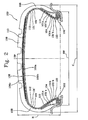
- Fig. 2 shows a further embodiment of a tire according to the present invention.
- Fig. 2 shows a tire (100) having the same structure as well as the same characteristics described in Fig. 1 , said tire (100) further comprising a second carcass ply (101'), applied externally over the first carcass ply (101), the end portions of which are associated with respective bead structures (103) comprising at least one bead core (102) and at least one bead filler (104).
- the association between the carcass ply (101') and the bead core (102) is achieved here by turning up the end portions of the carcass ply (101') around the bead core (102) so as to form the turned up carcass ply, said turned up carcass ply having an axially outer portion (101'a) and an axially inner portion (101b') as shown in Fig. 1 .
- said chafer (110) is placed at an axially inner position between the axially inner portion (1 01 b) of the turned up carcass ply and the axially inner portion (101'b) of the turned up carcass ply.
- Fig. 3 shows a further embodiment of a tire according to the present invention.
- Fig. 3 shows a tire (100) having the same structure as well as the same characteristics described in Fig. 1 , wherein said chafer (110) is placed at an axially inner position with respect to the axially inner portion (101b) of said turned up carcass ply.
- Fig. 4 shows a further embodiment of a tire according to the present invention.
- Fig. 4 shows a tire (100) having the same structure as well as the same characteristics described in Fig. 1 , wherein said chafer (110) is placed at an axially inner position with respect to the axially outer portion (101 a) of said turned up carcass ply.
- said chafer (110) starts in correspondence of the radially outer portion of said bed core (102), extends along the axially outer portion (101a) of said turned up carcass ply and directly contacts the same, and ends substantially in correspondence of the end portion of said at least one bead filler (104).
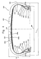
- Fig. 5 shows a further embodiment of a tire according to the present invention.
- Fig. 5 a tire (100) having the same structure as well as the same characteristics described in Fig. 1 , wherein said chafer (110) is placed at an axially outer position with respect to the axially inner portion (101 b) of said turned up carcass ply.
- said chafer (110) starts in correspondence of the radially outer portion of said bed core (102), extends along the axially inner portion (101b) of said turned up carcass ply and directly contacts the same, and ends substantially in correspondence of the end portion of said at least one bead filler (104).
- the tire according to the present invention i.e. the tire (100) represented in Fig. 1-5 , has an aspect ratio (H/C), lower than or equal to about 0.65, preferably lower than or equal to about 0.45, even more preferably lower than or equal to about 0.35.
- H/C aspect ratio
- Low aspect ratio values are advantageously used in "HP" or "UHP” tires.
- the tire according to the present invention is suitable for Sports Utility Vehicles (SUV) which combines the characteristics of comfort and roominess of a station wagon with high performances (especially in terms of high speeds) typical of high-powered cars.
- SUV Sports Utility Vehicles
- Fig. 6 shows a perspective view of a first reinforcing cord which is particularly useful for the aim of the present invention.
- the reinforcing cord (1) comprises a core made of two first elongated elements (2) arranged in parallel, said core being wrapped with one second elongated element (3).
- each one of said two first elongated elements is made of a plurality of elongated glass fibers embedded in a vinyl ester resin.
- said second elongated element is made of a single elementary steel wire (i.e. a monofilament).
- Example 2 a cord sample of Example 2 (comparative - i.e. reinforcing cord usually used in a tire chafer, in particular in a tire chafer for HP or UHP tires) and a cord sample of Example 4 (according to the present invention), each of said cord samples being previously rubberized by means of a laboratory extruder, was positioned onto a crosslinkable elastomeric material having a modulus at 100% elongation (100% Modulus) of 2.06 ⁇ 0.2 (said modulus being measured according to Standard ISO 37:2005), which was coupled with a steel tape.
- the cord sample ends and the steel tape ends were clamped and the so obtained test sample was vulcanized in a mould under predetermined vulcanizing conditions so as to obtain a single block.
- one end of the obtained single block is fixed onto the pure momentum dynamometer in such a way as to prevent its rotation only and not its planar movement while the other end is fixed so as to prevent its planar movement only and not its rotation, i.e. said single block was subjected to a pure bending momentum.
- reinforcing cords according to the present invention notwithstanding the remarkable weight reduction with respect to the steel reinforcing cords according to comparative examples, i.e. reinforcing cords usually used in a tire chafer, in particular in a tire chafer for HP or UHP tires, maintain substantially unchanged properties, in particular taber stiffness and elongation at break, while a sufficient breaking load is achieved.
Landscapes
- Engineering & Computer Science (AREA)
- Mechanical Engineering (AREA)
- Tires In General (AREA)
- Ropes Or Cables (AREA)
Claims (30)
- Reifen mit:- einem Paar Wulststrukturen (103), wobei die Wulststruktur (103) wenigstens einen Wulstkern (102) aufweist,- einer Karkassenstruktur, die eine im Wesentlichen ringförmige Gestalt aufweist, mit wenigstens einer Karkassenlage (101), die sich zwischen den Wulststrukturen (103) erstreckt und Endabschnitte, die den Wulstkernen (102) zugeordnet sind, aufweist,- wenigstens einer Verstärkungsschicht (110), die in Bezug auf den wenigstens einen Endabschnitt der wenigstens einen Karkassenlage (101) seitlich angebracht ist,- einer Gürtelstruktur (106), die an einer radial äußeren Position in Bezug auf die Karkassenstruktur angebracht ist,- einem Laufflächenband (109), das an einer radial äußeren Position in Bezug auf die Gürtelstruktur (106) angebracht ist,- einem Paar Seitenwände (108), die seitlich an gegenüberliegenden Seiten in Bezug auf die Karkassenstruktur angebracht sind,bei dem die wenigstens eine Verstärkungsschicht (110) wenigstens einen ersten Verstärkungskord (1) mit einem Kern (2) mit wenigstens einem ersten länglichen Element, das wenigstens einen Verbundwerkstoff aufweist, aufweist, dadurch gekennzeichnet, dass der Verbundwerkstoff mehrere längliche Fasern, die in ein Polymermaterial eingebettet sind, aufweist, bei dem der Kern (2) mit wenigstens einem zweiten länglichen Element (3) mit wenigstens einem elementaren Metalldraht umwickelt ist.
- Reifen nach Anspruch 1, bei dem die wenigstens eine Verstärkungsschicht (110) an einer axial äußeren Position mit Bezug auf den axial äußeren Abschnitt (101a) des wenigstens einen Endabschnitts der wenigstens einen Karkassenlage (101) platziert ist.
- Reifen nach Anspruch 1, bei dem die wenigstens eine Verstärkungsschicht (110) an einer axial inneren Position mit Bezug auf den axial inneren Abschnitt (101b) des wenigstens einen Endabschnitts der wenigstens einen Karkassenlage (101) platziert ist.
- Reifen nach Anspruch 1, bei dem die wenigstens eine Verstärkungsschicht (110) an einer in Bezug auf den axial äußeren Abschnitt (101a) des wenigstens einen Endabschnitts der wenigstens einen Karkassenlage (101) axial inneren Position platziert ist.
- Reifen nach Anspruch 1, bei dem der Reifen zwei Karkassenlagen (101, 101') aufweist, die Endabschnitte aufweisen, die den Wulstkernen (102) zugeordnet sind, wobei die wenigstens eine Verstärkungsschicht (110) zwischen den Endabschnitten der Karkassenlagen (101, 101') platziert ist.
- Reifen nach einem der vorherigen Ansprüche, bei dem die wenigstens eine Verstärkungsschicht (110) in Übereinstimmung mit dem radial äußeren Abschnitt des wenigstens einen Wulstkerns (102) beginnt, sich entlang des axial inneren Abschnitts (101b) oder des axial äußeren Abschnitts (101a) des wenigstens einen Endabschnitts der wenigstens einen Karkassenlage (101) erstreckt und sich radial nach außen mit Bezug auf den wenigstens einen Wulstkern (102) erstreckt.
- Reifen nach einem der vorherigen Ansprüche, bei dem sich die wenigstens eine Verstärkungsschicht (110) entlang der Reifenseitenwand (108) bis zu dem Ende der Reifengürtelstruktur (106) erstreckt.
- Reifen nach einem der vorherigen Ansprüche, bei dem der wenigstens eine erste Verstärkungskord (1) einen Kern (2) aufweist, der wenigstens zwei erste längliche Elemente aufweist, die parallel zueinander angeordnet sind.
- Reifen nach Anspruch 8, bei dem der wenigstens eine Verstärkungskord (1) einen Kern (2) mit wenigstens drei länglichen Elementen aufweist, die parallel zueinander angeordnet sind.
- Reifen nach einem der vorherigen Ansprüche, bei dem der Kern (2) mit nur einem zweiten länglichen Element (3) umwickelt ist, wobei das zweite längliche Element (3) wenigstens einen elementaren Metalldraht aufweist.
- Reifen nach einem der vorherigen Ansprüche, bei dem der Kern (2) mit wenigstens zwei oder mehr zweiten länglichen Elementen (3) umwickelt ist, wobei jedes der zweiten länglichen Elemente (3) wenigstens einen elementaren Metalldraht aufweist.
- Reifen nach Anspruch 11, bei dem die zweiten länglichen Elemente (3) parallel in der gleichen Richtung um den Kern (2) gewunden sind.
- Reifen nach einem der vorherigen Ansprüche, bei dem das wenigstens eine zweite längliche Element (3) aus einem einzelnen elementaren Metalldraht besteht.
- Reifen nach einem der vorherigen Ansprüche, bei dem das erste längliche Element einen Durchmesser von ungefähr 0,1 mm bis ungefähr 1,0 mm aufweist.
- Reifen nach einem der vorherigen Ansprüche, bei dem das zweite längliche Element einen Durchmesser von ungefähr 0,08 mm bis ungefähr 1,0 mm aufweist.
- Reifen nach einem der vorherigen Ansprüche, bei dem der Verstärkungskord (1) einen Durchmesser von ungefähr 0,3 mm bis ungefähr 2,0 mm aufweist.
- Reifen nach einem der vorherigen Ansprüche, bei dem das zweite längliche Element (3) um den Kern (2) mit einer Schlaglänge von ungefähr 2,5 mm bis ungefähr 30 mm gewunden ist.
- Reifen nach einem der vorherigen Ansprüche, bei dem der Verstärkungskord (1) eine Bruchdehnung, gemessen an dem blanken Kord, von größer oder gleich ungefähr 0,8% aufweist.
- Reifen nach einem der vorherigen Ansprüche, bei dem der Verstärkungskord (1) eine Steifigkeit, gemessen an dem blanken Kord, von größer oder gleich ungefähr 8 tsu aufweist.
- Reifen nach einem der vorherigen Ansprüche, bei dem der Verbundwerkstoff einen Biegemodul, gemessen bei 23°C nach der Norm ASTM D790-03, von größer oder gleich ungefähr 10 GPa aufweist.
- Reifen nach einem der vorherigen Ansprüche, bei dem der Verbundwerkstoff eine Zugfestigkeit, gemessen bei 23°C nach der Norm ASTM D3916-02, von größer oder gleich ungefähr 600 MPa aufweist.
- Reifen nach einem der vorherigen Ansprüche, bei dem der Verbundwerkstoff einen Zugmodul, gemessen bei 23°C nach der Norm ASTM D3916-02, von größer oder gleich ungefähr 20 GPa aufweist.
- Reifen nach einem der vorherigen Ansprüche, bei dem der Verbundwerkstoff eine spezifische Dichte, gemessen nach der Norm ASTM D792-00, von kleiner oder gleich ungefähr 3,0 g/cm3 aufweist.
- Reifen nach einem der vorherigen Ansprüche, bei dem das Polymermaterial einen Biegemodul, gemessen bei 23°C nach der Norm ASTM D790-03, von größer oder gleich ungefähr 0,5 GPa aufweist.
- Reifen nach einem der vorherigen Ansprüche, bei dem das Polymermaterial eine Zugfestigkeit, gemessen bei 23°C nach der Norm ASTM D638-03, von größer oder gleich ungefähr 40 MPa aufweist.
- Reifen nach einem der vorherigen Ansprüche, bei dem das Polymermaterial aus thermoplastischen Harzen, wärmehärtenden Harzen oder Mischungen davon ausgewählt ist.
- Reifen nach einem der vorherigen Ansprüche, bei dem die länglichen Fasern eine Zugfestigkeit, gemessen nach der Norm ASTM D885-03, von größer oder gleich ungefähr 1500 MPa aufweisen.
- Reifen nach einem der vorherigen Ansprüche, bei dem die länglichen Fasern einen Zugmodul, gemessen nach der Norm ASTM D885-03, von größer oder gleich ungefähr 50 GPa aufweisen.
- Reifen nach einem der vorherigen Ansprüche, bei dem die länglichen Fasern aus Glasfasern, aromatischen Polyamidfasern, Polyvinylalkoholfasern, Kohlefasern oder Mischungen davon ausgewählt sind.
- Reifen nach einem der vorherigen Ansprüche, bei dem die länglichen Fasern in dem Verbundwerkstoff in einer Menge von ungefähr 30 Gewichtsprozent bis zu ungefähr 95 Gewichtsprozent im Bezug auf das Gesamtgewicht des Verbundwerkstoffs enthalten sind.
Applications Claiming Priority (1)
| Application Number | Priority Date | Filing Date | Title |
|---|---|---|---|
| PCT/EP2007/011322 WO2009080077A1 (en) | 2007-12-21 | 2007-12-21 | Tire having a reinforced bead structure |
Publications (2)
| Publication Number | Publication Date |
|---|---|
| EP2237973A1 EP2237973A1 (de) | 2010-10-13 |
| EP2237973B1 true EP2237973B1 (de) | 2011-06-15 |
Family
ID=39712594
Family Applications (1)
| Application Number | Title | Priority Date | Filing Date |
|---|---|---|---|
| EP07866248A Active EP2237973B1 (de) | 2007-12-21 | 2007-12-21 | Reifen mit einer verstärkten wulststruktur |
Country Status (3)
| Country | Link |
|---|---|
| EP (1) | EP2237973B1 (de) |
| AT (1) | ATE512810T1 (de) |
| WO (1) | WO2009080077A1 (de) |
Cited By (1)
| Publication number | Priority date | Publication date | Assignee | Title |
|---|---|---|---|---|
| DE102016221021A1 (de) | 2016-10-26 | 2018-04-26 | Continental Reifen Deutschland Gmbh | Wulstverstärker zur mechanischen Verstärkung |
Families Citing this family (1)
| Publication number | Priority date | Publication date | Assignee | Title |
|---|---|---|---|---|
| EP3440245A1 (de) * | 2016-04-08 | 2019-02-13 | Gates Corporation | Hybridkabel zur verstärkung von polymerartikeln und verstärkten artikeln |
Family Cites Families (7)
| Publication number | Priority date | Publication date | Assignee | Title |
|---|---|---|---|---|
| JPS52155702A (en) * | 1976-06-22 | 1977-12-24 | Bridgestone Corp | Radial tyre having improved reinforcing structure at bead section |
| FR2781425B1 (fr) * | 1998-07-23 | 2000-09-01 | Michelin Rech Tech | Bourrelet renforce de pneumatique radial |
| WO2000020236A1 (en) * | 1998-10-01 | 2000-04-13 | The Goodyear Tire & Rubber Company | Improved construction for runflat tire |
| JP4315561B2 (ja) * | 2000-02-01 | 2009-08-19 | 住友ゴム工業株式会社 | 複合コードを用いた空気入りタイヤ |
| US6811877B2 (en) * | 2003-02-21 | 2004-11-02 | The Goodyear Tire & Rubber Company | Reinforcing structure |
| JP4549164B2 (ja) * | 2004-11-17 | 2010-09-22 | 住友ゴム工業株式会社 | 空気入りタイヤおよびその製造方法 |
| US7484545B2 (en) * | 2005-12-20 | 2009-02-03 | The Goodyear Tire & Rubber Co. | Radial tire for aircraft with specified merged cords |
-
2007
- 2007-12-21 AT AT07866248T patent/ATE512810T1/de not_active IP Right Cessation
- 2007-12-21 WO PCT/EP2007/011322 patent/WO2009080077A1/en active Application Filing
- 2007-12-21 EP EP07866248A patent/EP2237973B1/de active Active
Cited By (2)
| Publication number | Priority date | Publication date | Assignee | Title |
|---|---|---|---|---|
| DE102016221021A1 (de) | 2016-10-26 | 2018-04-26 | Continental Reifen Deutschland Gmbh | Wulstverstärker zur mechanischen Verstärkung |
| EP3315322A1 (de) | 2016-10-26 | 2018-05-02 | Continental Reifen Deutschland GmbH | Wulstverstärker zur mechanischen verstärkung |
Also Published As
| Publication number | Publication date |
|---|---|
| WO2009080077A1 (en) | 2009-07-02 |
| EP2237973A1 (de) | 2010-10-13 |
| ATE512810T1 (de) | 2011-07-15 |
Similar Documents
| Publication | Publication Date | Title |
|---|---|---|
| EP2089241B1 (de) | Reifen mit leichter gürtelstruktur | |
| EP2222480B1 (de) | Reifen mit einem mit einem hybridgarn verstärkten strukturelement | |
| EP1890892B1 (de) | Luftreifen mit verbundwulstkern | |
| US20110315296A1 (en) | Tire Having Low-Permeability Carcass Reinforcement Cable, and Textile Cords Associated with the Carcass Reinforcement | |
| US20120261046A1 (en) | Comprising Casing Reinforcement Cables Having a Low Perviousness, and Variable Rubber Mixture Thickness | |
| US20110308689A1 (en) | Tire Comprising Low Permeability Carcass Reinforcing Cables and Reduced Thicknesses of Rubber Compounds | |
| CN114929963B (zh) | 具有改进的断裂能和改进的总伸长的单层多线股帘线 | |
| EP0204237B1 (de) | Gürtelreifen für PKW | |
| EP0542567B1 (de) | Luftreifen | |
| EP2237973B1 (de) | Reifen mit einer verstärkten wulststruktur | |
| US6186205B1 (en) | Pneumatic tire for passenger cars including specified steel cord | |
| US20120060996A1 (en) | Reinforcement layer made of steel cords for belts of pneumatic vehicle tires | |
| WO2023228464A1 (ja) | タイヤ | |
| WO2019230761A1 (ja) | 空気入りタイヤ | |
| JP2023173881A (ja) | タイヤ | |
| CN118251316A (zh) | 充气轮胎 | |
| CN118354910A (zh) | 具有改进的弯曲耐久性的双层多线股帘线 | |
| CN117255878A (zh) | 具有改进的表面断裂能的双层多线股缆线 | |
| JPH11240311A (ja) | 空気入りラジアルタイヤ | |
| JP2000017588A (ja) | ゴム―スチ―ルコ―ド複合体及びそれを用いた乗用車用空気入りタイヤ |
Legal Events
| Date | Code | Title | Description |
|---|---|---|---|
| PUAI | Public reference made under article 153(3) epc to a published international application that has entered the european phase |
Free format text: ORIGINAL CODE: 0009012 |
|
| 17P | Request for examination filed |
Effective date: 20100720 |
|
| AK | Designated contracting states |
Kind code of ref document: A1 Designated state(s): AT BE BG CH CY CZ DE DK EE ES FI FR GB GR HU IE IS IT LI LT LU LV MC MT NL PL PT RO SE SI SK TR |
|
| AX | Request for extension of the european patent |
Extension state: AL BA HR MK RS |
|
| GRAP | Despatch of communication of intention to grant a patent |
Free format text: ORIGINAL CODE: EPIDOSNIGR1 |
|
| DAX | Request for extension of the european patent (deleted) | ||
| GRAS | Grant fee paid |
Free format text: ORIGINAL CODE: EPIDOSNIGR3 |
|
| GRAA | (expected) grant |
Free format text: ORIGINAL CODE: 0009210 |
|
| AK | Designated contracting states |
Kind code of ref document: B1 Designated state(s): AT BE BG CH CY CZ DE DK EE ES FI FR GB GR HU IE IS IT LI LT LU LV MC MT NL PL PT RO SE SI SK TR |
|
| REG | Reference to a national code |
Ref country code: GB Ref legal event code: FG4D Ref country code: CH Ref legal event code: EP |
|
| REG | Reference to a national code |
Ref country code: IE Ref legal event code: FG4D |
|
| REG | Reference to a national code |
Ref country code: DE Ref legal event code: R096 Ref document number: 602007015301 Country of ref document: DE Effective date: 20110804 |
|
| REG | Reference to a national code |
Ref country code: NL Ref legal event code: VDEP Effective date: 20110615 |
|
| PG25 | Lapsed in a contracting state [announced via postgrant information from national office to epo] |
Ref country code: LT Free format text: LAPSE BECAUSE OF FAILURE TO SUBMIT A TRANSLATION OF THE DESCRIPTION OR TO PAY THE FEE WITHIN THE PRESCRIBED TIME-LIMIT Effective date: 20110615 Ref country code: SE Free format text: LAPSE BECAUSE OF FAILURE TO SUBMIT A TRANSLATION OF THE DESCRIPTION OR TO PAY THE FEE WITHIN THE PRESCRIBED TIME-LIMIT Effective date: 20110615 |
|
| PG25 | Lapsed in a contracting state [announced via postgrant information from national office to epo] |
Ref country code: AT Free format text: LAPSE BECAUSE OF FAILURE TO SUBMIT A TRANSLATION OF THE DESCRIPTION OR TO PAY THE FEE WITHIN THE PRESCRIBED TIME-LIMIT Effective date: 20110615 Ref country code: SI Free format text: LAPSE BECAUSE OF FAILURE TO SUBMIT A TRANSLATION OF THE DESCRIPTION OR TO PAY THE FEE WITHIN THE PRESCRIBED TIME-LIMIT Effective date: 20110615 Ref country code: FI Free format text: LAPSE BECAUSE OF FAILURE TO SUBMIT A TRANSLATION OF THE DESCRIPTION OR TO PAY THE FEE WITHIN THE PRESCRIBED TIME-LIMIT Effective date: 20110615 Ref country code: GR Free format text: LAPSE BECAUSE OF FAILURE TO SUBMIT A TRANSLATION OF THE DESCRIPTION OR TO PAY THE FEE WITHIN THE PRESCRIBED TIME-LIMIT Effective date: 20110916 Ref country code: CY Free format text: LAPSE BECAUSE OF FAILURE TO SUBMIT A TRANSLATION OF THE DESCRIPTION OR TO PAY THE FEE WITHIN THE PRESCRIBED TIME-LIMIT Effective date: 20110615 Ref country code: LV Free format text: LAPSE BECAUSE OF FAILURE TO SUBMIT A TRANSLATION OF THE DESCRIPTION OR TO PAY THE FEE WITHIN THE PRESCRIBED TIME-LIMIT Effective date: 20110615 |
|
| PG25 | Lapsed in a contracting state [announced via postgrant information from national office to epo] |
Ref country code: BE Free format text: LAPSE BECAUSE OF FAILURE TO SUBMIT A TRANSLATION OF THE DESCRIPTION OR TO PAY THE FEE WITHIN THE PRESCRIBED TIME-LIMIT Effective date: 20110615 Ref country code: NL Free format text: LAPSE BECAUSE OF FAILURE TO SUBMIT A TRANSLATION OF THE DESCRIPTION OR TO PAY THE FEE WITHIN THE PRESCRIBED TIME-LIMIT Effective date: 20110615 |
|
| PG25 | Lapsed in a contracting state [announced via postgrant information from national office to epo] |
Ref country code: IS Free format text: LAPSE BECAUSE OF FAILURE TO SUBMIT A TRANSLATION OF THE DESCRIPTION OR TO PAY THE FEE WITHIN THE PRESCRIBED TIME-LIMIT Effective date: 20111015 Ref country code: PT Free format text: LAPSE BECAUSE OF FAILURE TO SUBMIT A TRANSLATION OF THE DESCRIPTION OR TO PAY THE FEE WITHIN THE PRESCRIBED TIME-LIMIT Effective date: 20111017 Ref country code: CZ Free format text: LAPSE BECAUSE OF FAILURE TO SUBMIT A TRANSLATION OF THE DESCRIPTION OR TO PAY THE FEE WITHIN THE PRESCRIBED TIME-LIMIT Effective date: 20110615 Ref country code: EE Free format text: LAPSE BECAUSE OF FAILURE TO SUBMIT A TRANSLATION OF THE DESCRIPTION OR TO PAY THE FEE WITHIN THE PRESCRIBED TIME-LIMIT Effective date: 20110615 |
|
| PG25 | Lapsed in a contracting state [announced via postgrant information from national office to epo] |
Ref country code: PL Free format text: LAPSE BECAUSE OF FAILURE TO SUBMIT A TRANSLATION OF THE DESCRIPTION OR TO PAY THE FEE WITHIN THE PRESCRIBED TIME-LIMIT Effective date: 20110615 Ref country code: SK Free format text: LAPSE BECAUSE OF FAILURE TO SUBMIT A TRANSLATION OF THE DESCRIPTION OR TO PAY THE FEE WITHIN THE PRESCRIBED TIME-LIMIT Effective date: 20110615 Ref country code: RO Free format text: LAPSE BECAUSE OF FAILURE TO SUBMIT A TRANSLATION OF THE DESCRIPTION OR TO PAY THE FEE WITHIN THE PRESCRIBED TIME-LIMIT Effective date: 20110615 |
|
| PLBE | No opposition filed within time limit |
Free format text: ORIGINAL CODE: 0009261 |
|
| STAA | Information on the status of an ep patent application or granted ep patent |
Free format text: STATUS: NO OPPOSITION FILED WITHIN TIME LIMIT |
|
| 26N | No opposition filed |
Effective date: 20120316 |
|
| PG25 | Lapsed in a contracting state [announced via postgrant information from national office to epo] |
Ref country code: DK Free format text: LAPSE BECAUSE OF FAILURE TO SUBMIT A TRANSLATION OF THE DESCRIPTION OR TO PAY THE FEE WITHIN THE PRESCRIBED TIME-LIMIT Effective date: 20110615 |
|
| REG | Reference to a national code |
Ref country code: DE Ref legal event code: R097 Ref document number: 602007015301 Country of ref document: DE Effective date: 20120316 |
|
| PG25 | Lapsed in a contracting state [announced via postgrant information from national office to epo] |
Ref country code: MC Free format text: LAPSE BECAUSE OF NON-PAYMENT OF DUE FEES Effective date: 20111231 |
|
| REG | Reference to a national code |
Ref country code: CH Ref legal event code: PL |
|
| REG | Reference to a national code |
Ref country code: IE Ref legal event code: MM4A |
|
| PG25 | Lapsed in a contracting state [announced via postgrant information from national office to epo] |
Ref country code: IE Free format text: LAPSE BECAUSE OF NON-PAYMENT OF DUE FEES Effective date: 20111221 Ref country code: CH Free format text: LAPSE BECAUSE OF NON-PAYMENT OF DUE FEES Effective date: 20111231 Ref country code: LI Free format text: LAPSE BECAUSE OF NON-PAYMENT OF DUE FEES Effective date: 20111231 |
|
| PG25 | Lapsed in a contracting state [announced via postgrant information from national office to epo] |
Ref country code: MT Free format text: LAPSE BECAUSE OF FAILURE TO SUBMIT A TRANSLATION OF THE DESCRIPTION OR TO PAY THE FEE WITHIN THE PRESCRIBED TIME-LIMIT Effective date: 20110615 |
|
| PG25 | Lapsed in a contracting state [announced via postgrant information from national office to epo] |
Ref country code: ES Free format text: LAPSE BECAUSE OF FAILURE TO SUBMIT A TRANSLATION OF THE DESCRIPTION OR TO PAY THE FEE WITHIN THE PRESCRIBED TIME-LIMIT Effective date: 20110926 |
|
| PG25 | Lapsed in a contracting state [announced via postgrant information from national office to epo] |
Ref country code: LU Free format text: LAPSE BECAUSE OF NON-PAYMENT OF DUE FEES Effective date: 20111221 |
|
| PG25 | Lapsed in a contracting state [announced via postgrant information from national office to epo] |
Ref country code: BG Free format text: LAPSE BECAUSE OF FAILURE TO SUBMIT A TRANSLATION OF THE DESCRIPTION OR TO PAY THE FEE WITHIN THE PRESCRIBED TIME-LIMIT Effective date: 20110915 |
|
| PG25 | Lapsed in a contracting state [announced via postgrant information from national office to epo] |
Ref country code: TR Free format text: LAPSE BECAUSE OF FAILURE TO SUBMIT A TRANSLATION OF THE DESCRIPTION OR TO PAY THE FEE WITHIN THE PRESCRIBED TIME-LIMIT Effective date: 20110615 |
|
| PG25 | Lapsed in a contracting state [announced via postgrant information from national office to epo] |
Ref country code: HU Free format text: LAPSE BECAUSE OF FAILURE TO SUBMIT A TRANSLATION OF THE DESCRIPTION OR TO PAY THE FEE WITHIN THE PRESCRIBED TIME-LIMIT Effective date: 20110615 |
|
| REG | Reference to a national code |
Ref country code: FR Ref legal event code: PLFP Year of fee payment: 9 |
|
| REG | Reference to a national code |
Ref country code: FR Ref legal event code: PLFP Year of fee payment: 10 |
|
| PG25 | Lapsed in a contracting state [announced via postgrant information from national office to epo] |
Ref country code: IT Free format text: LAPSE BECAUSE OF NON-PAYMENT OF DUE FEES Effective date: 20151221 |
|
| PG25 | Lapsed in a contracting state [announced via postgrant information from national office to epo] |
Ref country code: IT Free format text: LAPSE BECAUSE OF NON-PAYMENT OF DUE FEES Effective date: 20151221 |
|
| PGRI | Patent reinstated in contracting state [announced from national office to epo] |
Ref country code: IT Effective date: 20170710 |
|
| REG | Reference to a national code |
Ref country code: FR Ref legal event code: PLFP Year of fee payment: 11 |
|
| PGFP | Annual fee paid to national office [announced via postgrant information from national office to epo] |
Ref country code: GB Payment date: 20231227 Year of fee payment: 17 |
|
| PGFP | Annual fee paid to national office [announced via postgrant information from national office to epo] |
Ref country code: IT Payment date: 20231220 Year of fee payment: 17 Ref country code: FR Payment date: 20231227 Year of fee payment: 17 |
|
| PGFP | Annual fee paid to national office [announced via postgrant information from national office to epo] |
Ref country code: DE Payment date: 20231229 Year of fee payment: 17 |