EP2237445A2 - Apparatus and method for determining optimum integer perturbation vector of low complexity in multiple antenna system - Google Patents
Apparatus and method for determining optimum integer perturbation vector of low complexity in multiple antenna system Download PDFInfo
- Publication number
- EP2237445A2 EP2237445A2 EP10158430A EP10158430A EP2237445A2 EP 2237445 A2 EP2237445 A2 EP 2237445A2 EP 10158430 A EP10158430 A EP 10158430A EP 10158430 A EP10158430 A EP 10158430A EP 2237445 A2 EP2237445 A2 EP 2237445A2
- Authority
- EP
- European Patent Office
- Prior art keywords
- vector
- phase
- channel
- matrix
- transmission signal
- Prior art date
- Legal status (The legal status is an assumption and is not a legal conclusion. Google has not performed a legal analysis and makes no representation as to the accuracy of the status listed.)
- Granted
Links
Images


Classifications
-
- H—ELECTRICITY
- H04—ELECTRIC COMMUNICATION TECHNIQUE
- H04B—TRANSMISSION
- H04B1/00—Details of transmission systems, not covered by a single one of groups H04B3/00 - H04B13/00; Details of transmission systems not characterised by the medium used for transmission
- H04B1/38—Transceivers, i.e. devices in which transmitter and receiver form a structural unit and in which at least one part is used for functions of transmitting and receiving
-
- H—ELECTRICITY
- H04—ELECTRIC COMMUNICATION TECHNIQUE
- H04B—TRANSMISSION
- H04B7/00—Radio transmission systems, i.e. using radiation field
- H04B7/02—Diversity systems; Multi-antenna system, i.e. transmission or reception using multiple antennas
- H04B7/04—Diversity systems; Multi-antenna system, i.e. transmission or reception using multiple antennas using two or more spaced independent antennas
- H04B7/0413—MIMO systems
- H04B7/0452—Multi-user MIMO systems
-
- H—ELECTRICITY
- H04—ELECTRIC COMMUNICATION TECHNIQUE
- H04B—TRANSMISSION
- H04B7/00—Radio transmission systems, i.e. using radiation field
- H04B7/02—Diversity systems; Multi-antenna system, i.e. transmission or reception using multiple antennas
- H04B7/04—Diversity systems; Multi-antenna system, i.e. transmission or reception using multiple antennas using two or more spaced independent antennas
- H04B7/0413—MIMO systems
- H04B7/0456—Selection of precoding matrices or codebooks, e.g. using matrices antenna weighting
-
- H—ELECTRICITY
- H04—ELECTRIC COMMUNICATION TECHNIQUE
- H04B—TRANSMISSION
- H04B7/00—Radio transmission systems, i.e. using radiation field
- H04B7/14—Relay systems
-
- H—ELECTRICITY
- H04—ELECTRIC COMMUNICATION TECHNIQUE
- H04J—MULTIPLEX COMMUNICATION
- H04J11/00—Orthogonal multiplex systems, e.g. using WALSH codes
- H04J11/0023—Interference mitigation or co-ordination
- H04J11/0026—Interference mitigation or co-ordination of multi-user interference
- H04J11/003—Interference mitigation or co-ordination of multi-user interference at the transmitter
- H04J11/0033—Interference mitigation or co-ordination of multi-user interference at the transmitter by pre-cancellation of known interference, e.g. using a matched filter, dirty paper coder or Thomlinson-Harashima precoder
-
- H—ELECTRICITY
- H04—ELECTRIC COMMUNICATION TECHNIQUE
- H04L—TRANSMISSION OF DIGITAL INFORMATION, e.g. TELEGRAPHIC COMMUNICATION
- H04L25/00—Baseband systems
- H04L25/02—Details ; arrangements for supplying electrical power along data transmission lines
- H04L25/0202—Channel estimation
- H04L25/0204—Channel estimation of multiple channels
-
- H—ELECTRICITY
- H04—ELECTRIC COMMUNICATION TECHNIQUE
- H04L—TRANSMISSION OF DIGITAL INFORMATION, e.g. TELEGRAPHIC COMMUNICATION
- H04L25/00—Baseband systems
- H04L25/02—Details ; arrangements for supplying electrical power along data transmission lines
- H04L25/0202—Channel estimation
- H04L25/024—Channel estimation channel estimation algorithms
- H04L25/0242—Channel estimation channel estimation algorithms using matrix methods
- H04L25/0244—Channel estimation channel estimation algorithms using matrix methods with inversion
-
- H—ELECTRICITY
- H04—ELECTRIC COMMUNICATION TECHNIQUE
- H04L—TRANSMISSION OF DIGITAL INFORMATION, e.g. TELEGRAPHIC COMMUNICATION
- H04L25/00—Baseband systems
- H04L25/02—Details ; arrangements for supplying electrical power along data transmission lines
- H04L25/03—Shaping networks in transmitter or receiver, e.g. adaptive shaping networks
- H04L25/03006—Arrangements for removing intersymbol interference
- H04L25/03343—Arrangements at the transmitter end
Definitions
- the present invention relates to a multiple antenna system. More particularly, the present invention relates to an apparatus and a method for determining an optimum integer perturbation vector of a low complexity by representing a pseudo inverse matrix of a channel matrix and a transmission signal vector using real value representation, and decoupling real parts and imaginary parts of them in a multiple antenna system.
- MIMO Multiple Input Multiple Output
- a point-to-point MIMO technique for supporting a high information transmission rate
- multiple user MIMO techniques where a base station simultaneously considers a plurality of users who transmit data to a plurality of terminals, are being actively studied.
- information has to be simultaneously transmitted to a plurality of users in order to raise a transmission efficiency. More particularly, in the case where the number of transmission antennas is greater than the number of reception antennas, information has to be simultaneously transmitted to a plurality of users in order to obtain a maximum multiplexing efficiency.
- a signal of a certain user may act as an interference to a different user.
- the technique for canceling this interference signal may be classified into a transmission end interference cancel technique and a reception end interference cancel technique depending on a location of canceling the signal.
- a transmission end interference cancel technique When the number of transmission antennas is one, a method of decoding a signal of a different user and then canceling the signal at a reception end is best, and a transmission end interference cancel technique is not required.
- a transmission end interference cancel technique is not required.
- a Dirty Paper Coding (DPC) which is one of transmission end interference cancel techniques, supports a maximum information transmission rate.
- the DPC has a problem of having a considerably high calculation complexity.
- the VP technique is a linear pre-processing technique based on zero-forcing.
- a transmission end adds an integer perturbation vector to a desired signal vector in order to prevent a power boosting phenomenon.
- the VP technique may obtain a performance gain compared to an existing linear technique by adding an integer perturbation vector before sending a signal via a transmission antenna, but requires a high calculation complexity during a process of finding out an optimum integer perturbation vector whenever a channel response and a data signal change.
- an aspect of the present invention is to provide a transmitter/receiver and transmission/reception methods in a multiple antenna system.
- Another aspect of the present invention is to provide an apparatus and a method for determining an optimum integer perturbation vector of a low complexity in a multiple antenna system.
- a transmitter for transmitting data using an optimum integer perturbation vector of a low complexity in a multiple antenna system includes a modulo pre-processor for adding an integer perturbation vector to a transmission signal vector, a shift pre-processor for phase-shifting a pseudo inverse matrix of a channel matrix using a phase angle, and a precoder for precoding a transmission signal vector perturbed by the integer perturbation vector using the phase-shifted pseudo inverse matrix of the channel matrix.
- a transmitter for determining an optimum integer perturbation vector of a low complexity in a multiple antenna system includes a decoupler for decoupling a first channel vector and a second channel vector of a pseudo inverse matrix of a channel matrix, and decoupling a real part and an imaginary part of a transmission signal vector, and a perturbation vector determination unit for determining a real value and an imaginary value of the integer perturbation vector independently based on a first Equation below by coupling with the decoupled first channel vector and the decoupled real part of the transmission signal vector, and coupling with the decoupled second channel vector and the decoupled imaginary part of the transmission signal vector:
- a method for transmitting data using an optimum integer perturbation vector of a low complexity in a multiple antenna system includes adding an integer perturbation vector to a transmission signal vector, phase-shifting a pseudo inverse matrix of a channel matrix using a phase angle, and precoding a transmission signal vector perturbed by the integer perturbation vector using the phase-shifted pseudo inverse matrix of the channel matrix.
- a method for determining an optimum integer perturbation vector of a low complexity in a multiple antenna system includes decoupling a first channel vector and a second channel vector of a pseudo inverse matrix of a channel matrix, and decoupling a real part and an imaginary part of a transmission signal vector, and determining a real value and an imaginary value of the integer perturbation vector independently based on a first Equation below by coupling with the decoupled first channel vector and the decoupled real part of the transmission signal vector, and coupling with the decoupled second channel vector and the decoupled imaginary part of the transmission signal vector:
- an apparatus for determining an optimum integer perturbation vector of a low complexity in a multiple antenna system includes a shift corrector that performs phase compensation on a reception signal vector, a modulo corrector that cancels an integer perturbation vector component by performing a modulo operation on the phase-compensated reception signal, and a demodulator that demodulates a relevant bit from the reception signal vector from which the integer perturbation vector component has been cancelled.
- a method for determining an optimum integer perturbation vector of a low complexity in a multiple antenna system includes performing phase compensation on a reception signal vector, canceling an integer perturbation vector component by performing a modulo operation on the phase-compensated reception signal, and demodulating a relevant bit from the reception signal vector from which the integer perturbation vector component has been cancelled.
- FIG. 1 illustrates a transmitter for determining an optimum integer perturbation vector of a low complexity in a multiple antenna system according to an exemplary embodiment of the present invention
- FIG. 2 illustrates a receiver for determining an optimum integer perturbation vector of a low complexity in a multiple antenna system according to an exemplary embodiment of the present invention
- FIG. 3 illustrates an operation of a transmitter for determining an optimum integer perturbation vector of a low complexity in a multiple antenna system according to an exemplary embodiment of the present invention
- FIG. 4 illustrates an operation of a receiver for determining an optimum integer perturbation vector of a low complexity in a multiple antenna system according to an exemplary embodiment of the present invention.
- FIGURES 1 through 4 discussed below, and the various embodiments used to describe the principles of the present disclosure in this patent document are by way of illustration only and should not be construed in any way to limit the scope of the disclosure. Those skilled in the art will understand that the principles of the present disclosure may be implemented in any suitably arranged communication system.
- Exemplary embodiments of the present invention provide an apparatus and a method for determining an optimum integer perturbation vector of a low complexity in a multiple antenna system.
- the integer perturbation vector is a complex vector whose real part and imaginary part are integers.
- Exemplary embodiments of the present invention propose a method for decoupling a real part and an imaginary part, and determining the integer perturbation vector in order to reduce a calculation complexity when determining the integer perturbation vector.
- exemplary embodiments of the present invention propose a pre-processing technique applicable at a transmitter in order to reduce a loss occurring when a real part and an imaginary part of the integer perturbation vector are decoupled.
- FIG. 1 illustrates a transmitter that determines an optimum integer perturbation vector of a low complexity in a multiple antenna system according to an exemplary embodiment of the present invention.
- the transmitter includes a modulator 100, a modulo pre-processor 102, a shift pre-processor 104, a Zero Forcing (ZF) pre-processor 106, a unitization unit 108, a decoupler 110, a perturbation vector determination unit 112, and a phase determination unit 114.
- a modulator 100 a modulo pre-processor 102, a shift pre-processor 104, a Zero Forcing (ZF) pre-processor 106, a unitization unit 108, a decoupler 110, a perturbation vector determination unit 112, and a phase determination unit 114.
- ZF Zero Forcing
- the modulator 100 receives a bit stream for K users from an upper layer and maps bits to modulation symbols for each stream according to a relevant modulation scheme. That is, the modulator 100 maps predetermined bits to constellation points according to a relevant modulation scheme. The modulation symbol or the constellation point is expressed in terms of a complex data signal.
- the modulo pre-processor 102 receives K complex data signals (or modulation symbols), and receives the integer perturbation vector value from the perturbation vector determination unit 112 to perturb the complex data signal in order to prevent a transmission power increase phenomenon generated by ZF pre-processing (that is, to prevent an inverse matrix of a channel matrix from diverging). In other words, the modulo pre-processor 102 adds a complex integer vector (that is, an integer perturbation vector) multiplied by a constant ⁇ to the complex data signal.
- the shift pre-processor 104 performs phase shift on K perturbed complex data signals output from the modulo pre-processor 102 using K phase angles provided from the phase determination unit 114. That is, the shift pre-processor 104 shifts a phase of a complex data signal by a phase angle for each of K user streams (referring to Equation 13 herein below)
- the ZF pre-processor 106 multiples the complex data signal by a pseudo inverse matrix of a channel matrix phase-shifted by the shift pre-processor 104, and outputs the same to the unitization unit 108.
- the ZF pre-processor 106 cancels an interference between users by multiplying a transmission signal by the pseudo inverse matrix of the channel matrix and outputting the same.
- the unitization unit 108 multiplies an output signal from the ZF pre-processor 106 by 1 / ⁇ , and transmits the same via M transmission antennas.
- the decoupler 110 decouples real parts and imaginary parts of a channel matrix and a transmission signal vector modulated from the modulator 100, decouples a first channel vector and a second channel vector of a pseudo inverse matrix of the channel matrix (referring to Equation 8 below), and outputs them to the perturbation vector determination unit 112. Real parts and imaginary parts of the pseudo inverse matrix of the channel matrix and the transmission signal vector may be decoupled using real value representation.
- the perturbation vector determination unit 112 determines a real value and an imaginary value of a perturbation vector using real parts and imaginary parts of the pseudo inverse matrix of the channel matrix and the transmission signal vector, decoupled by the decoupler 110, and provides them to the modulo pre-processor 102. At this point, the perturbation vector determination unit 112 determines an optimum integer perturbation vector using phase-shifted results of decoupled real parts and imaginary parts of the pseudo inverse matrix of the channel matrix and the transmission signal vector from the shift pre-processor 104 (referring to Equations 7 and 11 below).
- the phase determination unit 114 determines phase angles ⁇ 1 , ⁇ , ⁇ K for respective K bit streams such that a real vector space and an imaginary vector space for a pseudo inverse matrix of a channel matrix are orthogonal.
- an optimum phase angle may be calculated through a repetitive algorithm (referring to Equation 12). For example, an optimum phase value is determined for ⁇ 1 with ⁇ 2 , ⁇ , ⁇ K fixed, and then an optimum phase value is determined for ⁇ 2 with ⁇ 1 and ⁇ 3 , ⁇ , ⁇ K fixed.
- optimum phase angles for phase angles ⁇ 3 , ⁇ , ⁇ K are determined with other phase angles excluding a relevant phase angle fixed (referring to Equation 17 below).
- one of K phase angles is selected from a real vector space and fixed (that is, a phase angle is set to zero), and a phase angle is determined such that one pseudo inverse matrix corresponding to the selected phase angle of the real vector space, and K pseudo inverse matrixes corresponding to K phase angles of an imaginary vector space are orthogonal.
- one of K phase angles is selected from an imaginary vector space and fixed (that is, a phase angle is set to zero), and a phase angle is determined such that one pseudo inverse matrix corresponding to the selected phase angle of the imaginary vector space and K pseudo inverse matrixes corresponding to K phase angles of a real vector space are orthogonal (referring to Equation 18).
- FIG. 2 illustrates a receiver that determines an optimum integer perturbation vector of a low complexity in a multiple antenna system according to an exemplary embodiment of the present invention.
- the receiver includes shift correctors 200_1 to 200_K, unitization correctors 202_1 to 202_K, modulo correctors 204_1 to 204_K, and demodulators 206_1 to 206_K (an index K is an index of a user receiver).
- K is an index of a user receiver.
- the shift correctors 200_1 to 200_K cancel an effect of a shift pre-process performed by a transmitter on a signal received via a reception antenna.
- the shift correctors perform compensation on the phase shift.
- the unitization correctors 202_1 to 202_N multiply a reception signal by ⁇ and outputs the same to the modulo correctors 204_1 to 204_K in order to cancel a unitization effect.
- the receiver since the transmitter multiplies a transmission signal by 1 / ⁇ to meet a power limit condition, the receiver performs compensation by multiplying a reception signal by ⁇ .
- the modulo correctors 204_1 to 204_K correct an effect of a modulo pre-process performed by the transmitter of FIG. 1 .
- the receiver cancels the integer perturbation vector added to the transmission vector through a modulo operation.
- the demodulators 206_1 to 206_K receive a complex signal including an effect of a noise, and detect a relevant bit signal.
- Equation 1 Equation 1:
- H ⁇ is a channel matrix
- x ⁇ is a transmission signal vector of M dimensions (M transmission antennas) and is a column vector listing signals transmitted via respective antennas
- ⁇ is a vector of noises generated from a reception antenna. Elements of the vector are independent and comply with a normal distribution whose average is 0 and whose dispersion is ⁇ n 2 .
- H ⁇ + is a pseudo inverse matrix of a channel matrix H ⁇ and is multiplied at the ZF pre-processor 106
- an effective channel gain that determines an entire performance of a perturbation vector system when an effect of a modulo operation is not considered is given by 1 / ⁇ for all users.
- an entire channel matrix H ⁇ is ill-conditioned, that is, directionality between rows of H ⁇ is similar or sizes of rows are small, a consequently obtained 1 / ⁇ value may be small, so that a system performance may reduce.
- the modulo pre-processor 102 adds a complex integer vector multiplied by a constant to a complex data signal (or modulation symbol) as in Equation 4:
- ⁇ is a complex data signal corresponding to K user streams
- ⁇ is a positive real number
- ⁇ is a complex integer vector
- a most difficult point in realizing a VP system is to determine an optimum perturbation vector ⁇ opt that may optimize a performance using Equation 5 when a channel matrix H ⁇ and a complex data vector ⁇ are given. That is, the most difficult point is to calculate ⁇ opt that minimizes a ⁇ value.
- I opt arg min I ⁇ ⁇ CZ K ⁇ ⁇ H ⁇ + ⁇ u ⁇ + ⁇ ⁇ I ⁇ ⁇ 2
- CZ K is a set of K-dimension vectors whose real and imaginary parts are integers.
- algorithms such as Sphere Encoding (SE) and Lattice-Reduction (LR) are used.
- Exemplary embodiments of the present invention provide a process that can effectively reduce a calculation complexity of SE and LR algorithms.
- Equation 6 A function to be minimized in Equation 5 is defined as Equation 6:
- Equation 6 may be expressed in terms of a real number system as in Equation 7:
- Equation 8 Equation 8
- Equation 9 ⁇ opt obtained using Equation 5 is expressed in terms of a real number system function as in Equation 9:
- an exemplary embodiment of the present invention proposes a method for decoupling integers corresponding to a real part and integers corresponding to an imaginary part as in Equation 10 and calculating ⁇ opt in order to reduce a complexity in calculation.
- Equation 11 r and ⁇ , and H e and ⁇ e are given by Equation 11:
- Equation 10 When a real part and an imaginary part are decoupled in order to calculate ⁇ opt in Equation 10 instead of Equation 5, a considerable amount of calculation gains is obtained, but a performance deterioration may occur. In this case, when a condition of Equation 12 is met, a performance deterioration may be reduced.
- span ( ) denotes a vector space to which vectors inside brackets extend
- ⁇ denotes orthogonality. That is, a shift pre-process is applied as in Equation 13 so that two vector spaces are nearly orthogonal.
- Equation 14 Equation 14:
- Equation 15 r ⁇ , ⁇ ⁇ , H e ⁇ , H ⁇ e ⁇ are given by Equation 15:
- Equation 16 h i , e + and h ⁇ i , e + are determined by Equation 16:
- diag( ) is a diagonal matrix whose diagonal elements are elements inside brackets.
- Chordal distance A representative criterion of orthogonality between two vector spaces is Chordal distance, which is defined by Equation 17:
- column vectors of Q include unit orthogonal basis vectors of span ⁇ h 1 , ⁇ + ⁇ h K , ⁇ + . That is, column vectors of Q are orthogonal to one another and are 1 in size, and can express all vectors of span ⁇ h 1 , ⁇ + ⁇ h K , ⁇ + through linear combination of them.
- column vectors of Q ⁇ include unit orthogonal basis vectors of h ⁇ 1 , ⁇ + , ⁇ , h ⁇ K , ⁇ + .
- ⁇ 2 ,..., ⁇ K may be optimized through a repetitive algorithm.
- ⁇ 2 ,..., ⁇ K may be optimized through an algorithm 1 below.
- Orthogonality may be maintained as in Equation 18 through the above algorithm.
- one of K phase angles is selected from a real vector space and fixed (that is, a phase angle is set to zero), and a phase angle is determined such that one pseudo inverse matrix corresponding to the selected phase angle of the real vector space, and K pseudo inverse matrixes corresponding to K phase angles of an imaginary vector space are orthogonal.
- one of K phase angles is selected from an imaginary vector space and fixed (that is, a phase angle is set to zero), and a phase angle is determined such that one pseudo inverse matrix corresponding to the selected phase angle of the imaginary vector space, and K pseudo inverse matrixes corresponding to K phase angles of a real vector space are orthogonal (referring to Equation 18).
- FIG. 3 illustrates an operation of a transmitter for determining an optimum integer perturbation vector of a low complexity in a multiple antenna system according to an exemplary embodiment of the present invention.
- the decoupler 110 expresses a transmission signal vector and a pseudo inverse matrix of a channel matrix using real value representation in step 300.
- the decoupler 110 decouples real parts and imaginary parts of the transmission signal vector and the pseudo inverse matrix of the channel matrix in step 302.
- the phase determination unit 114 determines phase angles ⁇ 1 ,..., ⁇ K for respective K bit streams so that a real vector space and an imaginary vector space for the pseudo inverse matrix of the channel matrix are orthogonal in order to reduce a loss generated when a real part and an imaginary part of an integer perturbation vector are decoupled in step 304.
- an optimum phase angle may be obtained through a repetitive algorithm (referring to Equation 12).
- one of K phase angles is selected from a real vector space and fixed (that is, a phase angle is set to zero), and a phase angle is determined such that one pseudo inverse matrix corresponding to the selected phase angle of the real vector space, and K pseudo inverse matrixes corresponding to K phase angles of an imaginary vector space are orthogonal.
- one of K phase angles is selected from an imaginary vector space and fixed (that is, a phase angle is set to zero), and a phase angle is determined such that one pseudo inverse matrix corresponding to the selected phase angle of the imaginary vector space, and K pseudo inverse matrixes corresponding to K phase angles of a real vector space are orthogonal (referring to Equation 18).
- the shift pre-processor 104 performs phase shift (referred to as diagonalisation pre-coding) on a pseudo inverse matrix of a channel matrix using the determined K phase angles in step 306.
- the perturbation vector determination unit 112 determines a real value and an imaginary value of a perturbation vector using decoupled real parts and imaginary parts of the pseudo inverse matrix of the channel matrix and the transmission signal vector in step 308. That is, the perturbation vector determination unit 112 determines an optimum perturbation vector from phase-shifted results of decoupled real parts and imaginary parts of the pseudo inverse matrix of the channel matrix and the transmission signal vector from the shift pre-processor 104 (referring to Equations 7 and 11).
- the modulo pre-processor 102 receives K complex data signal (or modulation symbol) and perturbs the transmission signal vector using the integer perturbation vector in order to prevent a transmission power increase phenomenon generated by ZF pre-processing (that is, to prevent an inverse matrix of a channel matrix from diverging), and the ZF pre-processor 106 multiplies a transmission signal by the pseudo inverse matrix of the channel matrix and outputs the same in step 310.
- the transmitter transmits the K phase angles determined in step 304 to a relevant user via unicasting or broadcasting in step 312.
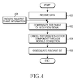
- FIG. 4 illustrates an operation of a receiver for determining an optimum integer perturbation vector of a low complexity in a multiple antenna system according to an exemplary embodiment of the present invention.
- the receiver receives data via reception antennas in step 400.
- the shift correctors 200_1 to 200_K cancel an effect of shift pre-process performed by the transmitter on a reception signal in step 402.
- the shift correctors perform compensation on the phase shift.
- the modulo correctors 204_1 to 204_K correct an effect of a modulo pre-process performed by the transmitter in step 404.
- the transmitter adds an integer perturbation vector to a transmission vector in order to prevent a power increase phenomenon generated by a ZF pre-process
- the receiver cancels the integer perturbation vector added to the transmission vector through a modulo operation.
- the demodulators 206_1 to 206_K demodulate a relevant bit from a reception signal vector from which an integer perturbation vector component has been cancelled in step 406.
- the receiver receives phase angle information unicast or broadcast from the transmitter in step 408.
- a pseudo inverse matrix of a channel matrix and a transmission signal vector are represented using real value representation in a multiple antenna system, and real parts and imaginary parts of them are decoupled, so that complexity may be reduced in determining an optimum integer perturbation vector.
- diagonalisation pre-coding is performed, so that performance deterioration generated by decoupling of real parts and imaginary parts of a pseudo inverse matrix of a channel matrix and a transmission signal vector may be minimized.
Abstract
Description
- The present invention relates to a multiple antenna system. More particularly, the present invention relates to an apparatus and a method for determining an optimum integer perturbation vector of a low complexity by representing a pseudo inverse matrix of a channel matrix and a transmission signal vector using real value representation, and decoupling real parts and imaginary parts of them in a multiple antenna system.
- Recently, a Multiple Input Multiple Output (MIMO) technique for supporting a high information transmission rate is widely used in a mobile communication field. Not only a point-to-point MIMO technique but also multiple user MIMO techniques where a base station simultaneously considers a plurality of users who transmit data to a plurality of terminals, are being actively studied. Unlike a point-to-point MIMO, under a multiple user environment, information has to be simultaneously transmitted to a plurality of users in order to raise a transmission efficiency. More particularly, in the case where the number of transmission antennas is greater than the number of reception antennas, information has to be simultaneously transmitted to a plurality of users in order to obtain a maximum multiplexing efficiency. At this point, one of problems that may occur is that a signal of a certain user may act as an interference to a different user. The technique for canceling this interference signal may be classified into a transmission end interference cancel technique and a reception end interference cancel technique depending on a location of canceling the signal. When the number of transmission antennas is one, a method of decoding a signal of a different user and then canceling the signal at a reception end is best, and a transmission end interference cancel technique is not required. In contrast, when the number of transmission antennas is two or more, a method of canceling an interference at a reception end is not best and a transmission end interference cancel technique needs to be used. A Dirty Paper Coding (DPC), which is one of transmission end interference cancel techniques, supports a maximum information transmission rate. However, the DPC has a problem of having a considerably high calculation complexity.
- Therefore, a Vector Perturbation (VP) technique having a lower calculation complexity than that of the DPC has been suggested. The VP technique is a linear pre-processing technique based on zero-forcing. In the VP technique, a transmission end adds an integer perturbation vector to a desired signal vector in order to prevent a power boosting phenomenon.
- As described above, the VP technique may obtain a performance gain compared to an existing linear technique by adding an integer perturbation vector before sending a signal via a transmission antenna, but requires a high calculation complexity during a process of finding out an optimum integer perturbation vector whenever a channel response and a data signal change.
- Therefore, an apparatus and a method for determining an optimum integer perturbation vector requiring a low complexity in a multiple antenna system are required.
- To address the above-discussed deficiencies of the prior art, it is a primary aspect of the present invention to solve at least the above-mentioned problems and/or disadvantages and to provide at least the advantages described below. Accordingly, an aspect of the present invention is to provide a transmitter/receiver and transmission/reception methods in a multiple antenna system.
- Another aspect of the present invention is to provide an apparatus and a method for determining an optimum integer perturbation vector of a low complexity in a multiple antenna system.
- In accordance with an aspect of the present invention, a transmitter for transmitting data using an optimum integer perturbation vector of a low complexity in a multiple antenna system is provided. The transmitter includes a modulo pre-processor for adding an integer perturbation vector to a transmission signal vector, a shift pre-processor for phase-shifting a pseudo inverse matrix of a channel matrix using a phase angle, and a precoder for precoding a transmission signal vector perturbed by the integer perturbation vector using the phase-shifted pseudo inverse matrix of the channel matrix.
- In accordance with another aspect of the present invention, a transmitter for determining an optimum integer perturbation vector of a low complexity in a multiple antenna system is provided. The transmitter includes a decoupler for decoupling a first channel vector and a second channel vector of a pseudo inverse matrix of a channel matrix, and decoupling a real part and an imaginary part of a transmission signal vector, and a perturbation vector determination unit for determining a real value and an imaginary value of the integer perturbation vector independently based on a first Equation below by coupling with the decoupled first channel vector and the decoupled real part of the transmission signal vector, and coupling with the decoupled second channel vector and the decoupled imaginary part of the transmission signal vector:
-

where
- In accordance with still another aspect of the present invention, a method for transmitting data using an optimum integer perturbation vector of a low complexity in a multiple antenna system is provided. The method includes adding an integer perturbation vector to a transmission signal vector, phase-shifting a pseudo inverse matrix of a channel matrix using a phase angle, and precoding a transmission signal vector perturbed by the integer perturbation vector using the phase-shifted pseudo inverse matrix of the channel matrix.
- In accordance with further another aspect of the present invention, a method for determining an optimum integer perturbation vector of a low complexity in a multiple antenna system is provided. The method includes decoupling a first channel vector and a second channel vector of a pseudo inverse matrix of a channel matrix, and decoupling a real part and an imaginary part of a transmission signal vector, and determining a real value and an imaginary value of the integer perturbation vector independently based on a first Equation below by coupling with the decoupled first channel vector and the decoupled real part of the transmission signal vector, and coupling with the decoupled second channel vector and the decoupled imaginary part of the transmission signal vector:
-

where
- In accordance with yet another aspect of the present invention, an apparatus for determining an optimum integer perturbation vector of a low complexity in a multiple antenna system is provided. The apparatus includes a shift corrector that performs phase compensation on a reception signal vector, a modulo corrector that cancels an integer perturbation vector component by performing a modulo operation on the phase-compensated reception signal, and a demodulator that demodulates a relevant bit from the reception signal vector from which the integer perturbation vector component has been cancelled.
- In accordance with yet further another aspect of the present invention, a method for determining an optimum integer perturbation vector of a low complexity in a multiple antenna system is provided. The method includes performing phase compensation on a reception signal vector, canceling an integer perturbation vector component by performing a modulo operation on the phase-compensated reception signal, and demodulating a relevant bit from the reception signal vector from which the integer perturbation vector component has been cancelled.
- Before undertaking the DETAILED DESCRIPTION OF THE INVENTION below, it may be advantageous to set forth definitions of certain words and phrases used throughout this patent document: the terms "include" and "comprise," as well as derivatives thereof, mean inclusion without limitation; the term "or," is inclusive, meaning and/or; the phrases "associated with" and "associated therewith," as well as derivatives thereof, may mean to include, be included within, interconnect with, contain, be contained within, connect to or with, couple to or with, be communicable with, cooperate with, interleave, juxtapose, be proximate to, be bound to or with, have, have a property of, or the like; and the term "controller" means any device, system or part thereof that controls at least one operation, such a device may be implemented in hardware, firmware or software, or some combination of at least two of the same. It should be noted that the functionality associated with any particular controller may be centralized or distributed, whether locally or remotely. Definitions for certain words and phrases are provided throughout this patent document, those of ordinary skill in the art should understand that in many, if not most instances, such definitions apply to prior, as well as future uses of such defined words and phrases.
- The above and other aspects, features and advantages of certain exemplary embodiments of the present invention will be more apparent from the following description taken in conjunction with the accompanying drawings in which:
-
FIG. 1 illustrates a transmitter for determining an optimum integer perturbation vector of a low complexity in a multiple antenna system according to an exemplary embodiment of the present invention; -
FIG. 2 illustrates a receiver for determining an optimum integer perturbation vector of a low complexity in a multiple antenna system according to an exemplary embodiment of the present invention; -
FIG. 3 illustrates an operation of a transmitter for determining an optimum integer perturbation vector of a low complexity in a multiple antenna system according to an exemplary embodiment of the present invention; and -
FIG. 4 illustrates an operation of a receiver for determining an optimum integer perturbation vector of a low complexity in a multiple antenna system according to an exemplary embodiment of the present invention. -
FIGURES 1 through 4 , discussed below, and the various embodiments used to describe the principles of the present disclosure in this patent document are by way of illustration only and should not be construed in any way to limit the scope of the disclosure. Those skilled in the art will understand that the principles of the present disclosure may be implemented in any suitably arranged communication system. - Preferred embodiments of the present invention will be described herein below with reference to the accompanying drawings. In the following description, detailed descriptions of well-known functions or constructions will be omitted since they would obscure the invention in unnecessary detail. Also, the terms used herein are defined according to the functions of the present invention. Thus, the terms may vary depending upon a user's or operator's intentions or practices. Therefore, the terms used herein should be understood based on the descriptions made herein.
- Exemplary embodiments of the present invention provide an apparatus and a method for determining an optimum integer perturbation vector of a low complexity in a multiple antenna system.
- The integer perturbation vector is a complex vector whose real part and imaginary part are integers. Exemplary embodiments of the present invention propose a method for decoupling a real part and an imaginary part, and determining the integer perturbation vector in order to reduce a calculation complexity when determining the integer perturbation vector. In addition, exemplary embodiments of the present invention propose a pre-processing technique applicable at a transmitter in order to reduce a loss occurring when a real part and an imaginary part of the integer perturbation vector are decoupled.
-
FIG. 1 illustrates a transmitter that determines an optimum integer perturbation vector of a low complexity in a multiple antenna system according to an exemplary embodiment of the present invention. - Referring to
FIG.1 , the transmitter includes amodulator 100, a modulo pre-processor 102, a shift pre-processor 104, a Zero Forcing (ZF) pre-processor 106, aunitization unit 108, adecoupler 110, a perturbationvector determination unit 112, and aphase determination unit 114. - The
modulator 100 receives a bit stream for K users from an upper layer and maps bits to modulation symbols for each stream according to a relevant modulation scheme. That is, themodulator 100 maps predetermined bits to constellation points according to a relevant modulation scheme. The modulation symbol or the constellation point is expressed in terms of a complex data signal. - The modulo
pre-processor 102 receives K complex data signals (or modulation symbols), and receives the integer perturbation vector value from the perturbationvector determination unit 112 to perturb the complex data signal in order to prevent a transmission power increase phenomenon generated by ZF pre-processing (that is, to prevent an inverse matrix of a channel matrix from diverging). In other words, the modulopre-processor 102 adds a complex integer vector (that is, an integer perturbation vector) multiplied by a constant τ to the complex data signal. - The
shift pre-processor 104 performs phase shift on K perturbed complex data signals output from the modulopre-processor 102 using K phase angles provided from thephase determination unit 114. That is, theshift pre-processor 104 shifts a phase of a complex data signal by a phase angle for each of K user streams (referring to Equation 13 herein below) - The
ZF pre-processor 106 multiples the complex data signal by a pseudo inverse matrix of a channel matrix phase-shifted by theshift pre-processor 104, and outputs the same to theunitization unit 108. TheZF pre-processor 106 cancels an interference between users by multiplying a transmission signal by the pseudo inverse matrix of the channel matrix and outputting the same. - The
unitization unit 108 multiplies an output signal from theZF pre-processor 106 by
- The
decoupler 110 decouples real parts and imaginary parts of a channel matrix and a transmission signal vector modulated from themodulator 100, decouples a first channel vector and a second channel vector of a pseudo inverse matrix of the channel matrix (referring to Equation 8 below), and outputs them to the perturbationvector determination unit 112. Real parts and imaginary parts of the pseudo inverse matrix of the channel matrix and the transmission signal vector may be decoupled using real value representation. - The perturbation
vector determination unit 112 determines a real value and an imaginary value of a perturbation vector using real parts and imaginary parts of the pseudo inverse matrix of the channel matrix and the transmission signal vector, decoupled by thedecoupler 110, and provides them to themodulo pre-processor 102. At this point, the perturbationvector determination unit 112 determines an optimum integer perturbation vector using phase-shifted results of decoupled real parts and imaginary parts of the pseudo inverse matrix of the channel matrix and the transmission signal vector from the shift pre-processor 104 (referring to Equations 7 and 11 below). - To reduce a loss generated when the perturbation
vector determination unit 112 decouples a real part and an imaginary part of the integer perturbation vector, thephase determination unit 114 determines phase angles θ1,···,θ K for respective K bit streams such that a real vector space and an imaginary vector space for a pseudo inverse matrix of a channel matrix are orthogonal. Here, an optimum phase angle may be calculated through a repetitive algorithm (referring to Equation 12). For example, an optimum phase value is determined for θ1 with θ2,···,θ K fixed, and then an optimum phase value is determined for θ2 with θ1 and θ3,···,θ K fixed. Likewise, optimum phase angles for phase angles θ3,···,θ K are determined with other phase angles excluding a relevant phase angle fixed (referring to Equation 17 below). - According to another exemplary embodiment, to calculate the phase angle, one of K phase angles is selected from a real vector space and fixed (that is, a phase angle is set to zero), and a phase angle is determined such that one pseudo inverse matrix corresponding to the selected phase angle of the real vector space, and K pseudo inverse matrixes corresponding to K phase angles of an imaginary vector space are orthogonal. In addition, one of K phase angles is selected from an imaginary vector space and fixed (that is, a phase angle is set to zero), and a phase angle is determined such that one pseudo inverse matrix corresponding to the selected phase angle of the imaginary vector space and K pseudo inverse matrixes corresponding to K phase angles of a real vector space are orthogonal (referring to Equation 18).
-
FIG. 2 illustrates a receiver that determines an optimum integer perturbation vector of a low complexity in a multiple antenna system according to an exemplary embodiment of the present invention. - Referring to
FIG. 2 , the receiver includes shift correctors 200_1 to 200_K, unitization correctors 202_1 to 202_K, modulo correctors 204_1 to 204_K, and demodulators 206_1 to 206_K (an index K is an index of a user receiver). Each of K users receives a transmission signal via N reception antennas. - The shift correctors 200_1 to 200_K cancel an effect of a shift pre-process performed by a transmitter on a signal received via a reception antenna. In other words, since a phase shift has been performed for respective K bit streams in order to reduce system performance deterioration generated when the transmitter decouples a real part and an imaginary part of a pseudo inverse matrix of a channel matrix, the shift correctors perform compensation on the phase shift.
- The unitization correctors 202_1 to 202_N multiply a reception signal by


- The modulo correctors 204_1 to 204_K correct an effect of a modulo pre-process performed by the transmitter of
FIG. 1 . In other words, since the transmitter adds an integer perturbation vector to a transmission vector in order to prevent a power increase phenomenon generated by a ZF pre-process, the receiver cancels the integer perturbation vector added to the transmission vector through a modulo operation. - The demodulators 206_1 to 206_K receive a complex signal including an effect of a noise, and detect a relevant bit signal.
- For clearer mathematical description, an entire reception signal vector of K dimensions (K streams) is expressed using Equation 1:
-

- where H̃ is a channel matrix, and x̃ is a transmission signal vector of M dimensions (M transmission antennas) and is a column vector listing signals transmitted via respective antennas, and ñ is a vector of noises generated from a reception antenna. Elements of the vector are independent and comply with a normal distribution whose average is 0 and whose dispersion is

complex signals corresponding to a bit stream of each user is denoted by ũ, a transmission signal vector is given by Equation 2: -

- where H̃+ is a pseudo inverse matrix of a channel matrix H̃ and is multiplied at the
ZF pre-processor 106, and
unitization unit 108. - At this point, after a transmission signal vector is pre-processed by the
ZF pre-processor 106, a reception signal is given by Equation 3: -

- Consequently, an effective channel gain that determines an entire performance of a perturbation vector system when an effect of a modulo operation is not considered is given by


pre-processor 102 adds a complex integer vector multiplied by a constant to a complex data signal (or modulation symbol) as in Equation 4: -

- where ũ is a complex data signal corresponding to K user streams, τ is a positive real number, and Ĩ is a complex integer vector.
- The reason a complex integer vector instead of a general complex vector is added is to allow a receiver to correct an effect of addition of τĨ based on a modulo operation and perform decoding.
- Generally, a most difficult point in realizing a VP system is to determine an optimum perturbation vector Ĩopt that may optimize a performance using Equation 5 when a channel matrix H̃ and a complex data vector ũ are given. That is, the most difficult point is to calculate Ĩopt that minimizes a γ value.
-

- where CZK is a set of K-dimension vectors whose real and imaginary parts are integers. To effectively calculate Equation 1, algorithms such as Sphere Encoding (SE) and Lattice-Reduction (LR) are used. Exemplary embodiments of the present invention provide a process that can effectively reduce a calculation complexity of SE and LR algorithms.
- A function to be minimized in Equation 5 is defined as Equation 6:
-

- where


- where, for an arbitrary complex number ã , aI and aQ are a real part and an imaginary part of ã , respectively, and


-

- Ĩopt obtained using Equation 5 is expressed in terms of a real number system function as in Equation 9:
-

- Here, to obtain an optimum perturbation vector using Equation 9, 2K integers have to be searched for simultaneously. Therefore, an exemplary embodiment of the present invention proposes a method for decoupling integers corresponding to a real part and integers corresponding to an imaginary part as in Equation 10 and calculating Ĩopt in order to reduce a complexity in calculation.
-

- Here, r and ṙ, and He and Ḣe are given by Equation 11:
-

- When a real part and an imaginary part are decoupled in order to calculate Ĩopt in Equation 10 instead of Equation 5, a considerable amount of calculation gains is obtained, but a performance deterioration may occur. In this case, when a condition of Equation 12 is met, a performance deterioration may be reduced.
-

where span ( ) denotes a vector space to which vectors inside brackets extend, and ⊥ denotes orthogonality. That is, a shift pre-process is applied as in Equation 13 so that two vector spaces are nearly orthogonal. -

- When shift pre-process is applied as in Equation 13, Equation 10 may be expressed by Equation 14:
-

- Here, rθ,ṙθ,

-

-


-

- where diag( ) is a diagonal matrix whose diagonal elements are elements inside brackets.
- That is, directionality between


- A representative criterion of orthogonality between two vector spaces is Chordal distance, which is defined by Equation 17:
-

- Here, column vectors of Q include unit orthogonal basis vectors of


- Here, θ2,...,θK may be optimized through a repetitive algorithm.
- According to another exemplary embodiment, θ2,...,θK may be optimized through an algorithm 1 below.
- For i=2:K

end - Orthogonality may be maintained as in Equation 18 through the above algorithm.
-

- That is, to calculate the phase angles θ2,...,θK, one of K phase angles is selected from a real vector space and fixed (that is, a phase angle is set to zero), and a phase angle is determined such that one pseudo inverse matrix corresponding to the selected phase angle of the real vector space, and K pseudo inverse matrixes corresponding to K phase angles of an imaginary vector space are orthogonal. In addition, one of K phase angles is selected from an imaginary vector space and fixed (that is, a phase angle is set to zero), and a phase angle is determined such that one pseudo inverse matrix corresponding to the selected phase angle of the imaginary vector space, and K pseudo inverse matrixes corresponding to K phase angles of a real vector space are orthogonal (referring to Equation 18).
-
FIG. 3 illustrates an operation of a transmitter for determining an optimum integer perturbation vector of a low complexity in a multiple antenna system according to an exemplary embodiment of the present invention. - Referring to
FIG. 3 , thedecoupler 110 expresses a transmission signal vector and a pseudo inverse matrix of a channel matrix using real value representation instep 300. - The
decoupler 110 decouples real parts and imaginary parts of the transmission signal vector and the pseudo inverse matrix of the channel matrix instep 302. - The
phase determination unit 114 determines phase angles θ1,...,θK for respective K bit streams so that a real vector space and an imaginary vector space for the pseudo inverse matrix of the channel matrix are orthogonal in order to reduce a loss generated when a real part and an imaginary part of an integer perturbation vector are decoupled instep 304. Here, an optimum phase angle may be obtained through a repetitive algorithm (referring to Equation 12). - According to another exemplary embodiment, to calculate the phase angle, one of K phase angles is selected from a real vector space and fixed (that is, a phase angle is set to zero), and a phase angle is determined such that one pseudo inverse matrix corresponding to the selected phase angle of the real vector space, and K pseudo inverse matrixes corresponding to K phase angles of an imaginary vector space are orthogonal. In addition, one of K phase angles is selected from an imaginary vector space and fixed (that is, a phase angle is set to zero), and a phase angle is determined such that one pseudo inverse matrix corresponding to the selected phase angle of the imaginary vector space, and K pseudo inverse matrixes corresponding to K phase angles of a real vector space are orthogonal (referring to Equation 18).
- The
shift pre-processor 104 performs phase shift (referred to as diagonalisation pre-coding) on a pseudo inverse matrix of a channel matrix using the determined K phase angles instep 306. - The perturbation
vector determination unit 112 determines a real value and an imaginary value of a perturbation vector using decoupled real parts and imaginary parts of the pseudo inverse matrix of the channel matrix and the transmission signal vector instep 308. That is, the perturbationvector determination unit 112 determines an optimum perturbation vector from phase-shifted results of decoupled real parts and imaginary parts of the pseudo inverse matrix of the channel matrix and the transmission signal vector from the shift pre-processor 104 (referring to Equations 7 and 11). - The modulo
pre-processor 102 receives K complex data signal (or modulation symbol) and perturbs the transmission signal vector using the integer perturbation vector in order to prevent a transmission power increase phenomenon generated by ZF pre-processing (that is, to prevent an inverse matrix of a channel matrix from diverging), and theZF pre-processor 106 multiplies a transmission signal by the pseudo inverse matrix of the channel matrix and outputs the same instep 310. - The transmitter transmits the K phase angles determined in
step 304 to a relevant user via unicasting or broadcasting instep 312. - After that, the procedure ends.
-
FIG. 4 illustrates an operation of a receiver for determining an optimum integer perturbation vector of a low complexity in a multiple antenna system according to an exemplary embodiment of the present invention. - Referring to
FIG. 4 , the receiver receives data via reception antennas instep 400. The shift correctors 200_1 to 200_K cancel an effect of shift pre-process performed by the transmitter on a reception signal instep 402. In other words, since a phase shift has been performed for respective K bit streams in order to reduce system performance deterioration generated when the transmitter decouples a real part and an imaginary part of a pseudo inverse matrix of a channel matrix, the shift correctors perform compensation on the phase shift. - The modulo correctors 204_1 to 204_K correct an effect of a modulo pre-process performed by the transmitter in
step 404. In other words, since the transmitter adds an integer perturbation vector to a transmission vector in order to prevent a power increase phenomenon generated by a ZF pre-process, the receiver cancels the integer perturbation vector added to the transmission vector through a modulo operation. - The demodulators 206_1 to 206_K demodulate a relevant bit from a reception signal vector from which an integer perturbation vector component has been cancelled in
step 406. - The receiver receives phase angle information unicast or broadcast from the transmitter in
step 408. - After that, the procedure ends.
- As described above, a pseudo inverse matrix of a channel matrix and a transmission signal vector are represented using real value representation in a multiple antenna system, and real parts and imaginary parts of them are decoupled, so that complexity may be reduced in determining an optimum integer perturbation vector. In addition, diagonalisation pre-coding is performed, so that performance deterioration generated by decoupling of real parts and imaginary parts of a pseudo inverse matrix of a channel matrix and a transmission signal vector may be minimized.
- While the invention has been shown and described with reference to certain preferred embodiments thereof, it will be understood by those skilled in the art that various changes in form and details may be made therein without departing from the spirit and scope of the invention as defined by the appended claims.
Claims (15)
- A transmitter capable of transmitting data using an optimum integer perturbation vector of a low complexity in a multiple antenna system, the transmitter comprising:a modulo pre-processor (102) configured to add an integer perturbation vector to a transmission signal vector;a shift pre-processor (104) configured to phase-shift a pseudo inverse matrix of a channel matrix using a phase angle; anda precoder configured to precode a transmission signal vector perturbed by the integer perturbation vector using the phase-shifted pseudo inverse matrix of the channel matrix.
- A method for transmitting data using an optimum integer perturbation vector of a low complexity in a multiple antenna system, the method comprising:adding (310) an integer perturbation vector to a transmission signal vector;phase-shifting (306) a pseudo inverse matrix of a channel matrix using a phase angle; andprecoding (306) a transmission signal vector perturbed by the integer perturbation vector using the phase-shifted pseudo inverse matrix of the channel matrix.
- The transmitter of claim 1, further comprising:a decoupler (110) configured to decouple a first channel vector and a second channel vector of a pseudo inverse matrix of a channel matrix, and decoupling a real part and an imaginary part of a transmission signal vector; anda perturbation vector determination unit (112) configured to determine a real value and an imaginary value of the integer perturbation vector independently based on a first equation by coupling with the decoupled first channel vector and the decoupled real part of the transmission signal vector, and coupling with the decoupled second channel vector and the decoupled imaginary part of the transmission signal vector, the first equation defined as:

where
- The method of claim 2, further comprising:decoupling (300) a first channel vector and a second channel vector of a pseudo inverse matrix of a channel matrix, and decoupling (302) a real part and an imaginary part of a transmission signal vector; anddetermining (308) a real value and an imaginary value of the integer perturbation vector independently based on a second equation by coupling with the decoupled first channel vector and the decoupled real part of the transmission signal vector, and coupling with the decoupled second channel vector and the decoupled imaginary part of the transmission signal vector, the second equation defined as:

where
- The transmitter of claim 3 and the method of claim 4, wherein the first channel vector and the second channel vector are defined by a third equation:

where


- The transmitter of claim 1 and the method of claim 2, wherein the phase angle is determined through a repetitive process:for i=2:K

- The transmitter of claim 1 and the method of claim 2, wherein the phase angle is determined based on:

where

- A receiver for determining an optimum integer perturbation vector of a low complexity in a multiple antenna system, the receiver comprising:a shift corrector (200) configured to perform phase compensation on a reception signal vector;a modulo corrector (204) configured to cancel an integer perturbation vector component by performing a modulo operation on the phase-compensated reception signal vector; anda demodulator (206) configured to demodulate a relevant bit from the reception signal vector from which the integer perturbation vector component has been cancelled.
- A method for determining an optimum integer perturbation vector of a low complexity in a multiple antenna system, the method comprising:performing phase compensation (402) on a reception signal vector;canceling an integer perturbation vector component (404) by performing a modulo operation on the phase-compensated reception signal vector; anddemodulating a relevant bit (406) from the reception signal vector from which the integer perturbation vector component has been cancelled.
- The receiver of claim 8, wherein the phase compensation is compensation for phase shift for each user, for allowing a real vector space and an imaginary vector space to be orthogonal in a pseudo inverse matrix of a channel matrix.
- The method of claim 9, wherein the phase compensation is compensation for phase shift for each user, for allowing a real vector space and an imaginary vector space to be orthogonal in a pseudo inverse matrix of a channel matrix.
- The receiver of claim 10, wherein a phase angle for the phase compensation is determined through a repetitive process defined by:for i=2:K

- The receiver of claim 10, wherein a phase angle for the phase compensation is determined based on a first equation:

where

- The method of claim 11, wherein a phase angle for the phase compensation is determined through a repetitive process defined by:for i=2:K

- The method of claim 11, wherein a phase angle for the phase compensation is determined based on a second equation :

where

Applications Claiming Priority (1)
| Application Number | Priority Date | Filing Date | Title |
|---|---|---|---|
| KR1020090028380A KR101471077B1 (en) | 2009-04-02 | Apparatus and method for determining an optimal integer constellation vector of low complexity in a multiple antenna system |
Publications (4)
| Publication Number | Publication Date |
|---|---|
| EP2237445A2 true EP2237445A2 (en) | 2010-10-06 |
| EP2237445A3 EP2237445A3 (en) | 2013-02-27 |
| EP2237445B1 EP2237445B1 (en) | 2014-08-27 |
| EP2237445B8 EP2237445B8 (en) | 2014-11-12 |
Family
ID=42308009
Family Applications (1)
| Application Number | Title | Priority Date | Filing Date |
|---|---|---|---|
| EP10158430.8A Active EP2237445B8 (en) | 2009-04-02 | 2010-03-30 | Apparatus and method for determining optimum integer perturbation vector of low complexity in multiple antenna system |
Country Status (3)
| Country | Link |
|---|---|
| US (1) | US8358718B2 (en) |
| EP (1) | EP2237445B8 (en) |
| CN (1) | CN101860388B (en) |
Cited By (3)
| Publication number | Priority date | Publication date | Assignee | Title |
|---|---|---|---|---|
| WO2016082871A1 (en) * | 2014-11-25 | 2016-06-02 | Telefonaktiebolaget Lm Ericsson (Publ) | A radio transmitter for distortion mitigation |
| CN113965234A (en) * | 2021-10-21 | 2022-01-21 | 西安邮电大学 | RIS-enabled uplink random disturbance alignment pre-coding spatial modulation method |
| US11881914B1 (en) | 2020-06-01 | 2024-01-23 | Space Exploration Technologies Corp. | Determination of electronic beam steering angles |
Families Citing this family (9)
| Publication number | Priority date | Publication date | Assignee | Title |
|---|---|---|---|---|
| KR101268687B1 (en) * | 2008-08-18 | 2013-05-29 | 한국전자통신연구원 | Communication system including basestations and terminal for multi-cell cooperative communication |
| MX2013000953A (en) | 2011-02-18 | 2013-02-15 | Panasonic Corp | Method of signal generation and signal generating device. |
| WO2012144206A1 (en) | 2011-04-19 | 2012-10-26 | パナソニック株式会社 | Signal generating method and signal generating device |
| WO2013048065A2 (en) * | 2011-09-27 | 2013-04-04 | Jang Jung-Yup | Orthogonal complex pre-coding apparatus and method in an open loop multi-antenna system |
| EP3437197B1 (en) * | 2016-04-01 | 2022-03-09 | Cohere Technologies, Inc. | Tomlinson-harashima precoding in an otfs communication system |
| CN109257311B (en) * | 2017-07-14 | 2021-04-16 | 北京中科晶上科技股份有限公司 | Method and system for determining error vector magnitude |
| WO2020056593A1 (en) * | 2018-09-18 | 2020-03-26 | Oppo广东移动通信有限公司 | Signal processing method and device and storage medium |
| CN112332945A (en) * | 2019-08-05 | 2021-02-05 | 大唐移动通信设备有限公司 | Physical layer secure transmission method, transmitting terminal and target receiving terminal |
| US11956006B2 (en) * | 2022-07-01 | 2024-04-09 | Qualcomm Incorporated | Precoding perturbation to allow large array digital post distortion |
Family Cites Families (12)
| Publication number | Priority date | Publication date | Assignee | Title |
|---|---|---|---|---|
| US7272454B2 (en) * | 2003-06-05 | 2007-09-18 | Fisher-Rosemount Systems, Inc. | Multiple-input/multiple-output control blocks with non-linear predictive capabilities |
| CA2490969C (en) * | 2004-01-02 | 2014-06-17 | Her Majesty In Right Of Canada As Represented By The Minister Of Industry, Through The Communications Research Centre Canada | Method for updating singular value decomposition of a transfer matrix |
| CN100388645C (en) * | 2004-09-28 | 2008-05-14 | 上海贝尔阿尔卡特股份有限公司 | Pre-coding method and device for improving V-BLAST detection performance |
| US7899421B2 (en) * | 2005-09-21 | 2011-03-01 | Broadcom Corporation | Double search algorithm of user group selection for multiuser MIMO downlink transmission |
| US7917100B2 (en) * | 2005-09-21 | 2011-03-29 | Broadcom Corporation | Method and system for a double search user group selection scheme with range in TDD multiuser MIMO downlink transmission |
| WO2007061416A1 (en) * | 2005-11-23 | 2007-05-31 | Nokia Corporation | Joint optimization of linear pre-filtering and nonlinear vector perturbation for mimo multiuser precoding |
| KR20080072164A (en) * | 2007-02-01 | 2008-08-06 | 엘지전자 주식회사 | Method for selecting antenna of mimo system and transmitter |
| KR100966522B1 (en) * | 2007-04-09 | 2010-06-29 | 삼성전자주식회사 | Apparatus and method for supporting a distortionless vector perturbation in muliple antenna system |
| CN101340219B (en) * | 2007-07-04 | 2012-10-03 | 华为技术有限公司 | Channel status information feeding back method and wireless transmitting/receiving device |
| US8009757B2 (en) * | 2007-11-12 | 2011-08-30 | Motorola Mobility, Inc. | Method and apparatus for encoding a modulated signal in a communication system |
| CN101227217B (en) * | 2008-02-04 | 2011-04-27 | 浙江大学 | Method and system for random wave packet forming based on multi-aerial receiver |
| GB2458883B (en) * | 2008-03-20 | 2010-09-29 | Toshiba Res Europ Ltd | Wireless communication apparatus |
-
2010
- 2010-03-30 US US12/798,185 patent/US8358718B2/en active Active
- 2010-03-30 EP EP10158430.8A patent/EP2237445B8/en active Active
- 2010-04-02 CN CN201010155264.6A patent/CN101860388B/en active Active
Non-Patent Citations (1)
| Title |
|---|
| None |
Cited By (5)
| Publication number | Priority date | Publication date | Assignee | Title |
|---|---|---|---|---|
| WO2016082871A1 (en) * | 2014-11-25 | 2016-06-02 | Telefonaktiebolaget Lm Ericsson (Publ) | A radio transmitter for distortion mitigation |
| US10218421B2 (en) | 2014-11-25 | 2019-02-26 | Telefonaktiebolaget Lm Ericsson (Publ) | Radio transmitter for distortion mitigation |
| US11881914B1 (en) | 2020-06-01 | 2024-01-23 | Space Exploration Technologies Corp. | Determination of electronic beam steering angles |
| CN113965234A (en) * | 2021-10-21 | 2022-01-21 | 西安邮电大学 | RIS-enabled uplink random disturbance alignment pre-coding spatial modulation method |
| CN113965234B (en) * | 2021-10-21 | 2022-07-12 | 西安邮电大学 | RIS-enabled uplink random disturbance alignment pre-coding spatial modulation method |
Also Published As
| Publication number | Publication date |
|---|---|
| US20100254487A1 (en) | 2010-10-07 |
| EP2237445A3 (en) | 2013-02-27 |
| US8358718B2 (en) | 2013-01-22 |
| CN101860388A (en) | 2010-10-13 |
| EP2237445B8 (en) | 2014-11-12 |
| CN101860388B (en) | 2015-04-01 |
| EP2237445B1 (en) | 2014-08-27 |
| KR20100110026A (en) | 2010-10-12 |
Similar Documents
| Publication | Publication Date | Title |
|---|---|---|
| EP2237445B1 (en) | Apparatus and method for determining optimum integer perturbation vector of low complexity in multiple antenna system | |
| CN102150377B (en) | Antenna selection and soft demapping for MIMO decoding | |
| US7907912B2 (en) | Apparatus and method for eliminating multi-user interference | |
| US8964889B2 (en) | Device and method for precoding vectors in a communication system | |
| EP2315365B1 (en) | Method, communication system and related equipments for data transmission | |
| US8442139B2 (en) | Apparatus and method for transmitting and receiving in a multi-antenna system | |
| EP2533449A1 (en) | Transmitter apparatus, receiver apparatus, wireless communication system, transmission control method, reception control method, and processor | |
| CN101682379A (en) | The method and apparatus that is used for the feedback of closed loop transmit | |
| US7957479B2 (en) | Apparatus and method for supporting distortionless vector perturbation in multiple antenna system | |
| US7839810B2 (en) | Transmitter, communication system and communication method | |
| EP2266211B1 (en) | Apparatus and method for transmitting pilot signal in wireless communication system | |
| US20130344908A1 (en) | Method and apparatus for interference processing in wireless communication system | |
| KR100869070B1 (en) | Apparatus and method for beamforming in multi input multi output system | |
| US9148780B2 (en) | Method and apparatus for secure data transmission | |
| US8217835B2 (en) | Method and apparatus for beam-forming signal in multi user-MIMO wireless communication system | |
| CN107733492A (en) | Data sending, receiving method and device | |
| Kong et al. | Joint MMSE transceiver designs for MIMO AF relaying systems with direct link | |
| US7965783B2 (en) | Method and system for transmitting data streams via a beamformed MIMO channel | |
| CN107094124B (en) | Downlink multi-user multi-antenna data transmission method, device and system | |
| US8483305B2 (en) | Apparatus and method for spatial multiplexing in multi input multi output system | |
| CN102404090B (en) | Downlink transmission method for multi-user MIMO (Multiple Input Multiple Output) system based on singular value decomposition | |
| CN110518942B (en) | User scheduling method of large-scale MIMO double-loop relay system | |
| KR101471077B1 (en) | Apparatus and method for determining an optimal integer constellation vector of low complexity in a multiple antenna system | |
| CN102201890B (en) | Data transmitting method and device | |
| KR20100012283A (en) | Apparatus and method for regularized coordinated beamforming in multiple antenna |
Legal Events
| Date | Code | Title | Description |
|---|---|---|---|
| PUAI | Public reference made under article 153(3) epc to a published international application that has entered the european phase |
Free format text: ORIGINAL CODE: 0009012 |
|
| AK | Designated contracting states |
Kind code of ref document: A2 Designated state(s): AT BE BG CH CY CZ DE DK EE ES FI FR GB GR HR HU IE IS IT LI LT LU LV MC MK MT NL NO PL PT RO SE SI SK SM TR |
|
| AX | Request for extension of the european patent |
Extension state: AL BA ME RS |
|
| RAP1 | Party data changed (applicant data changed or rights of an application transferred) |
Owner name: KOREA UNIVERSITY INDUSTRIAL & ACADEMIC COLLABORATI Owner name: SAMSUNG ELECTRONICS CO., LTD. |
|
| PUAL | Search report despatched |
Free format text: ORIGINAL CODE: 0009013 |
|
| AK | Designated contracting states |
Kind code of ref document: A3 Designated state(s): AT BE BG CH CY CZ DE DK EE ES FI FR GB GR HR HU IE IS IT LI LT LU LV MC MK MT NL NO PL PT RO SE SI SK SM TR |
|
| AX | Request for extension of the european patent |
Extension state: AL BA ME RS |
|
| RIC1 | Information provided on ipc code assigned before grant |
Ipc: H04J 11/00 20060101ALI20130121BHEP Ipc: H04L 25/02 20060101ALI20130121BHEP Ipc: H04L 25/03 20060101ALI20130121BHEP Ipc: H04L 1/06 20060101ALI20130121BHEP Ipc: H04B 7/04 20060101AFI20130121BHEP |
|
| 17P | Request for examination filed |
Effective date: 20130827 |
|
| RIC1 | Information provided on ipc code assigned before grant |
Ipc: H04L 25/03 20060101ALI20140225BHEP Ipc: H04L 25/02 20060101ALI20140225BHEP Ipc: H04L 1/06 20060101ALI20140225BHEP Ipc: H04J 11/00 20060101ALI20140225BHEP Ipc: H04B 7/04 20060101AFI20140225BHEP |
|
| GRAP | Despatch of communication of intention to grant a patent |
Free format text: ORIGINAL CODE: EPIDOSNIGR1 |
|
| INTG | Intention to grant announced |
Effective date: 20140423 |
|
| GRAS | Grant fee paid |
Free format text: ORIGINAL CODE: EPIDOSNIGR3 |
|
| GRAA | (expected) grant |
Free format text: ORIGINAL CODE: 0009210 |
|
| AK | Designated contracting states |
Kind code of ref document: B1 Designated state(s): AT BE BG CH CY CZ DE DK EE ES FI FR GB GR HR HU IE IS IT LI LT LU LV MC MK MT NL NO PL PT RO SE SI SK SM TR |
|
| REG | Reference to a national code |
Ref country code: GB Ref legal event code: FG4D |
|
| REG | Reference to a national code |
Ref country code: CH Ref legal event code: EP |
|
| REG | Reference to a national code |
Ref country code: AT Ref legal event code: REF Ref document number: 684939 Country of ref document: AT Kind code of ref document: T Effective date: 20140915 |
|
| REG | Reference to a national code |
Ref country code: IE Ref legal event code: FG4D |
|
| REG | Reference to a national code |
Ref country code: DE Ref legal event code: R096 Ref document number: 602010018504 Country of ref document: DE Effective date: 20141009 |
|
| RAP2 | Party data changed (patent owner data changed or rights of a patent transferred) |
Owner name: KOREA UNIVERSITY RESEARCH AND BUSINESS FOUNDATION Owner name: SAMSUNG ELECTRONICS CO., LTD. |
|
| REG | Reference to a national code |
Ref country code: AT Ref legal event code: MK05 Ref document number: 684939 Country of ref document: AT Kind code of ref document: T Effective date: 20140827 |
|
| REG | Reference to a national code |
Ref country code: LT Ref legal event code: MG4D |
|
| REG | Reference to a national code |
Ref country code: NL Ref legal event code: VDEP Effective date: 20140827 |
|
| PG25 | Lapsed in a contracting state [announced via postgrant information from national office to epo] |
Ref country code: PT Free format text: LAPSE BECAUSE OF FAILURE TO SUBMIT A TRANSLATION OF THE DESCRIPTION OR TO PAY THE FEE WITHIN THE PRESCRIBED TIME-LIMIT Effective date: 20141229 Ref country code: GR Free format text: LAPSE BECAUSE OF FAILURE TO SUBMIT A TRANSLATION OF THE DESCRIPTION OR TO PAY THE FEE WITHIN THE PRESCRIBED TIME-LIMIT Effective date: 20141128 Ref country code: BG Free format text: LAPSE BECAUSE OF FAILURE TO SUBMIT A TRANSLATION OF THE DESCRIPTION OR TO PAY THE FEE WITHIN THE PRESCRIBED TIME-LIMIT Effective date: 20141127 Ref country code: SE Free format text: LAPSE BECAUSE OF FAILURE TO SUBMIT A TRANSLATION OF THE DESCRIPTION OR TO PAY THE FEE WITHIN THE PRESCRIBED TIME-LIMIT Effective date: 20140827 Ref country code: LT Free format text: LAPSE BECAUSE OF FAILURE TO SUBMIT A TRANSLATION OF THE DESCRIPTION OR TO PAY THE FEE WITHIN THE PRESCRIBED TIME-LIMIT Effective date: 20140827 Ref country code: FI Free format text: LAPSE BECAUSE OF FAILURE TO SUBMIT A TRANSLATION OF THE DESCRIPTION OR TO PAY THE FEE WITHIN THE PRESCRIBED TIME-LIMIT Effective date: 20140827 Ref country code: ES Free format text: LAPSE BECAUSE OF FAILURE TO SUBMIT A TRANSLATION OF THE DESCRIPTION OR TO PAY THE FEE WITHIN THE PRESCRIBED TIME-LIMIT Effective date: 20140827 Ref country code: NO Free format text: LAPSE BECAUSE OF FAILURE TO SUBMIT A TRANSLATION OF THE DESCRIPTION OR TO PAY THE FEE WITHIN THE PRESCRIBED TIME-LIMIT Effective date: 20141127 |
|
| PG25 | Lapsed in a contracting state [announced via postgrant information from national office to epo] |
Ref country code: CY Free format text: LAPSE BECAUSE OF FAILURE TO SUBMIT A TRANSLATION OF THE DESCRIPTION OR TO PAY THE FEE WITHIN THE PRESCRIBED TIME-LIMIT Effective date: 20140827 Ref country code: HR Free format text: LAPSE BECAUSE OF FAILURE TO SUBMIT A TRANSLATION OF THE DESCRIPTION OR TO PAY THE FEE WITHIN THE PRESCRIBED TIME-LIMIT Effective date: 20140827 Ref country code: AT Free format text: LAPSE BECAUSE OF FAILURE TO SUBMIT A TRANSLATION OF THE DESCRIPTION OR TO PAY THE FEE WITHIN THE PRESCRIBED TIME-LIMIT Effective date: 20140827 Ref country code: LV Free format text: LAPSE BECAUSE OF FAILURE TO SUBMIT A TRANSLATION OF THE DESCRIPTION OR TO PAY THE FEE WITHIN THE PRESCRIBED TIME-LIMIT Effective date: 20140827 Ref country code: IS Free format text: LAPSE BECAUSE OF FAILURE TO SUBMIT A TRANSLATION OF THE DESCRIPTION OR TO PAY THE FEE WITHIN THE PRESCRIBED TIME-LIMIT Effective date: 20141227 |
|
| PG25 | Lapsed in a contracting state [announced via postgrant information from national office to epo] |
Ref country code: NL Free format text: LAPSE BECAUSE OF FAILURE TO SUBMIT A TRANSLATION OF THE DESCRIPTION OR TO PAY THE FEE WITHIN THE PRESCRIBED TIME-LIMIT Effective date: 20140827 |
|
| PG25 | Lapsed in a contracting state [announced via postgrant information from national office to epo] |
Ref country code: EE Free format text: LAPSE BECAUSE OF FAILURE TO SUBMIT A TRANSLATION OF THE DESCRIPTION OR TO PAY THE FEE WITHIN THE PRESCRIBED TIME-LIMIT Effective date: 20140827 Ref country code: CZ Free format text: LAPSE BECAUSE OF FAILURE TO SUBMIT A TRANSLATION OF THE DESCRIPTION OR TO PAY THE FEE WITHIN THE PRESCRIBED TIME-LIMIT Effective date: 20140827 Ref country code: IT Free format text: LAPSE BECAUSE OF FAILURE TO SUBMIT A TRANSLATION OF THE DESCRIPTION OR TO PAY THE FEE WITHIN THE PRESCRIBED TIME-LIMIT Effective date: 20140827 Ref country code: RO Free format text: LAPSE BECAUSE OF FAILURE TO SUBMIT A TRANSLATION OF THE DESCRIPTION OR TO PAY THE FEE WITHIN THE PRESCRIBED TIME-LIMIT Effective date: 20140827 Ref country code: SK Free format text: LAPSE BECAUSE OF FAILURE TO SUBMIT A TRANSLATION OF THE DESCRIPTION OR TO PAY THE FEE WITHIN THE PRESCRIBED TIME-LIMIT Effective date: 20140827 Ref country code: DK Free format text: LAPSE BECAUSE OF FAILURE TO SUBMIT A TRANSLATION OF THE DESCRIPTION OR TO PAY THE FEE WITHIN THE PRESCRIBED TIME-LIMIT Effective date: 20140827 |
|
| REG | Reference to a national code |
Ref country code: DE Ref legal event code: R097 Ref document number: 602010018504 Country of ref document: DE |
|
| PG25 | Lapsed in a contracting state [announced via postgrant information from national office to epo] |
Ref country code: PL Free format text: LAPSE BECAUSE OF FAILURE TO SUBMIT A TRANSLATION OF THE DESCRIPTION OR TO PAY THE FEE WITHIN THE PRESCRIBED TIME-LIMIT Effective date: 20140827 |
|
| PLBE | No opposition filed within time limit |
Free format text: ORIGINAL CODE: 0009261 |
|
| STAA | Information on the status of an ep patent application or granted ep patent |
Free format text: STATUS: NO OPPOSITION FILED WITHIN TIME LIMIT |
|
| 26N | No opposition filed |
Effective date: 20150528 |
|
| PG25 | Lapsed in a contracting state [announced via postgrant information from national office to epo] |
Ref country code: LU Free format text: LAPSE BECAUSE OF FAILURE TO SUBMIT A TRANSLATION OF THE DESCRIPTION OR TO PAY THE FEE WITHIN THE PRESCRIBED TIME-LIMIT Effective date: 20150330 Ref country code: MC Free format text: LAPSE BECAUSE OF FAILURE TO SUBMIT A TRANSLATION OF THE DESCRIPTION OR TO PAY THE FEE WITHIN THE PRESCRIBED TIME-LIMIT Effective date: 20140827 |
|
| REG | Reference to a national code |
Ref country code: CH Ref legal event code: PL |
|
| PG25 | Lapsed in a contracting state [announced via postgrant information from national office to epo] |
Ref country code: SI Free format text: LAPSE BECAUSE OF FAILURE TO SUBMIT A TRANSLATION OF THE DESCRIPTION OR TO PAY THE FEE WITHIN THE PRESCRIBED TIME-LIMIT Effective date: 20140827 |
|
| REG | Reference to a national code |
Ref country code: IE Ref legal event code: MM4A |
|
| PG25 | Lapsed in a contracting state [announced via postgrant information from national office to epo] |
Ref country code: CH Free format text: LAPSE BECAUSE OF NON-PAYMENT OF DUE FEES Effective date: 20150331 Ref country code: LI Free format text: LAPSE BECAUSE OF NON-PAYMENT OF DUE FEES Effective date: 20150331 Ref country code: IE Free format text: LAPSE BECAUSE OF NON-PAYMENT OF DUE FEES Effective date: 20150330 |
|
| REG | Reference to a national code |
Ref country code: FR Ref legal event code: PLFP Year of fee payment: 7 |
|
| PG25 | Lapsed in a contracting state [announced via postgrant information from national office to epo] |
Ref country code: BE Free format text: LAPSE BECAUSE OF FAILURE TO SUBMIT A TRANSLATION OF THE DESCRIPTION OR TO PAY THE FEE WITHIN THE PRESCRIBED TIME-LIMIT Effective date: 20140827 |
|
| PG25 | Lapsed in a contracting state [announced via postgrant information from national office to epo] |
Ref country code: MT Free format text: LAPSE BECAUSE OF FAILURE TO SUBMIT A TRANSLATION OF THE DESCRIPTION OR TO PAY THE FEE WITHIN THE PRESCRIBED TIME-LIMIT Effective date: 20140827 |
|
| REG | Reference to a national code |
Ref country code: FR Ref legal event code: PLFP Year of fee payment: 8 |
|
| PG25 | Lapsed in a contracting state [announced via postgrant information from national office to epo] |
Ref country code: HU Free format text: LAPSE BECAUSE OF FAILURE TO SUBMIT A TRANSLATION OF THE DESCRIPTION OR TO PAY THE FEE WITHIN THE PRESCRIBED TIME-LIMIT; INVALID AB INITIO Effective date: 20100330 Ref country code: SM Free format text: LAPSE BECAUSE OF FAILURE TO SUBMIT A TRANSLATION OF THE DESCRIPTION OR TO PAY THE FEE WITHIN THE PRESCRIBED TIME-LIMIT Effective date: 20140827 |
|
| PG25 | Lapsed in a contracting state [announced via postgrant information from national office to epo] |
Ref country code: TR Free format text: LAPSE BECAUSE OF FAILURE TO SUBMIT A TRANSLATION OF THE DESCRIPTION OR TO PAY THE FEE WITHIN THE PRESCRIBED TIME-LIMIT Effective date: 20140827 |
|
| REG | Reference to a national code |
Ref country code: FR Ref legal event code: PLFP Year of fee payment: 9 |
|
| PG25 | Lapsed in a contracting state [announced via postgrant information from national office to epo] |
Ref country code: MK Free format text: LAPSE BECAUSE OF FAILURE TO SUBMIT A TRANSLATION OF THE DESCRIPTION OR TO PAY THE FEE WITHIN THE PRESCRIBED TIME-LIMIT Effective date: 20140827 |
|
| PGFP | Annual fee paid to national office [announced via postgrant information from national office to epo] |
Ref country code: FR Payment date: 20230221 Year of fee payment: 14 |
|
| PGFP | Annual fee paid to national office [announced via postgrant information from national office to epo] |
Ref country code: GB Payment date: 20230220 Year of fee payment: 14 Ref country code: DE Payment date: 20230220 Year of fee payment: 14 |