EP2237416A1 - Device comprising an electroacoustic balun - Google Patents
Device comprising an electroacoustic balun Download PDFInfo
- Publication number
- EP2237416A1 EP2237416A1 EP09156769A EP09156769A EP2237416A1 EP 2237416 A1 EP2237416 A1 EP 2237416A1 EP 09156769 A EP09156769 A EP 09156769A EP 09156769 A EP09156769 A EP 09156769A EP 2237416 A1 EP2237416 A1 EP 2237416A1
- Authority
- EP
- European Patent Office
- Prior art keywords
- electrode
- pair
- electrodes
- film
- overlaps
- Prior art date
- Legal status (The legal status is an assumption and is not a legal conclusion. Google has not performed a legal analysis and makes no representation as to the accuracy of the status listed.)
- Withdrawn
Links
- 230000010287 polarization Effects 0.000 claims abstract description 44
- 239000000463 material Substances 0.000 claims abstract description 10
- 238000000034 method Methods 0.000 claims description 3
- 230000008878 coupling Effects 0.000 abstract description 7
- 238000010168 coupling process Methods 0.000 abstract description 7
- 238000005859 coupling reaction Methods 0.000 abstract description 7
- 238000006073 displacement reaction Methods 0.000 description 10
- 230000000694 effects Effects 0.000 description 5
- 230000005684 electric field Effects 0.000 description 5
- 230000001419 dependent effect Effects 0.000 description 4
- 239000013078 crystal Substances 0.000 description 3
- 238000004519 manufacturing process Methods 0.000 description 3
- 239000000758 substrate Substances 0.000 description 3
- 230000008901 benefit Effects 0.000 description 2
- 230000008859 change Effects 0.000 description 2
- 238000006243 chemical reaction Methods 0.000 description 2
- 230000006835 compression Effects 0.000 description 2
- 238000007906 compression Methods 0.000 description 2
- 238000000151 deposition Methods 0.000 description 2
- 238000000059 patterning Methods 0.000 description 2
- 238000004590 computer program Methods 0.000 description 1
- 230000008021 deposition Effects 0.000 description 1
- 230000003287 optical effect Effects 0.000 description 1
- 230000003252 repetitive effect Effects 0.000 description 1
- 238000003860 storage Methods 0.000 description 1
- 230000009466 transformation Effects 0.000 description 1
Images


Classifications
-
- H—ELECTRICITY
- H03—ELECTRONIC CIRCUITRY
- H03H—IMPEDANCE NETWORKS, e.g. RESONANT CIRCUITS; RESONATORS
- H03H9/00—Networks comprising electromechanical or electro-acoustic elements; Electromechanical resonators
- H03H9/0023—Networks for transforming balanced signals into unbalanced signals and vice versa, e.g. baluns, or networks having balanced input and output
- H03H9/0095—Networks for transforming balanced signals into unbalanced signals and vice versa, e.g. baluns, or networks having balanced input and output using bulk acoustic wave devices
-
- H—ELECTRICITY
- H03—ELECTRONIC CIRCUITRY
- H03H—IMPEDANCE NETWORKS, e.g. RESONANT CIRCUITS; RESONATORS
- H03H9/00—Networks comprising electromechanical or electro-acoustic elements; Electromechanical resonators
- H03H9/0023—Networks for transforming balanced signals into unbalanced signals and vice versa, e.g. baluns, or networks having balanced input and output
- H03H9/0028—Networks for transforming balanced signals into unbalanced signals and vice versa, e.g. baluns, or networks having balanced input and output using surface acoustic wave devices
-
- H—ELECTRICITY
- H03—ELECTRONIC CIRCUITRY
- H03H—IMPEDANCE NETWORKS, e.g. RESONANT CIRCUITS; RESONATORS
- H03H9/00—Networks comprising electromechanical or electro-acoustic elements; Electromechanical resonators
- H03H9/46—Filters
- H03H9/54—Filters comprising resonators of piezoelectric or electrostrictive material
- H03H9/56—Monolithic crystal filters
- H03H9/564—Monolithic crystal filters implemented with thin-film techniques
Definitions
- the invention relates to a device that comprises an electroacoustic balun.
- An electroacoustic balun device is known from US patent No 7,091,649 .
- the balun comprises two stacks, each with two resonant piezoelectric layers, one above the other, with electrodes in the stack on either side of each layer.
- voltages are applied between the electrodes of the resonator in a first one of the piezoelectric layers. This results in acoustic vibrations in the resonator in the first piezoelectric layer, which are coupled to the second one of the piezoelectric layers so that vibrations also occur in the second piezoelectric layer. Due to the piezoelectric effect this in turn results in a voltage across the electrodes of the second piezoelectric layer.
- US patent No 7,091,649 describes a device with two of such stacks, using separate electrodes.
- voltages are applied between the electrodes of the resonators of both stacks in the first piezoelectric layer, to produce voltages between the electrodes of the resonators in the second piezoelectric layer.
- the polarization of the piezoelectric layers is set differently in the different stacks, in order to create a phase relation between the resulting voltages from the resonators in the second layer so that the series connection of these resonators produces twice the voltage applied to the series connection of the resonators in the first layer.
- balun functionality can be realized.
- US 3,018,415 discloses a resonator comprising a piezoelectric crystal with two electrodes on respective sides of the crystal. In order to suppress undesirable vibration modes at least one of the electrodes is shaped into a central disc and a surrounding ring, and the polarization of the crystal is set in mutually opposite directions below the disc and the ring respectively.
- US 5,576,590 discloses an electroacoustic transformer with a driver part and a generator part.
- the transformer comprises a piezoelectric plate.
- electrodes are attached on mutually opposite sides of the plate to excite acoustic vibrations. These vibrations travel outward from the driver part as an acoustic wave with longitudinal polarization (i.e. with vibrating movement in the direction of propagation in the plane of the plate).
- the generator part comprises electrodes at different positions on the plate. In the generator part the plate is polarized between these positions, in order to convert the waves into electric fields in the plane of the plate between the electrodes.
- US 6,448,695 discloses a frequency bandpass filter that is formed using a series arrangement of acoustic resonators. Coupling between the resonators is realized acoustically rather than electronically, by means of lateral wave coupling.
- a device which comprises an electroacoustic balun.
- at least three electrodes are provided on the same surface of a film, which may act as terminals of the balun.
- the edges of the electrodes face each other in two identical interfaces.
- the directions of the components of piezoelectric polarization perpendicular to the film are the same underneath the electrodes of one interface. Underneath the electrodes of the other interface the directions of these components are mutually opposite.
- a single piezoelectric film is sufficient to form the acoustic part of a balun.
- the use of the same film makes it easy to match the resonance frequencies.
- the interfaces are realized between a first electrode and separate second electrodes.
- first electrode has a mirror symmetric shape, with the second electrodes facing edges of the first electrode that are related by a symmetry transformation.
- coupling to the second electrodes can be easily matched.
- first electrodes are used on the surface of the film, electrically connected to each other, each with an interface to a respective second electrode.
- the second electrodes are located between the first electrodes.
- the first electrodes have identical shape. This makes it easy to improve matching of resonance frequencies.
- the polarization components underneath the two first electrodes have mutually opposite directions. In this way a large region with the same polarization direction can be used underneath the other first electrode and the second electrodes.
- the second electrodes have identical shapes. This makes it easy to improve matching of resonance frequencies.
- a common electrode is used on the surface opposite the first and second electrodes, having overlaps with the first and second electrodes. Alternatively, separate electrodes may be used on that surface. The use of a common electrode makes it possible to realize a simple structure with little or no height variations.
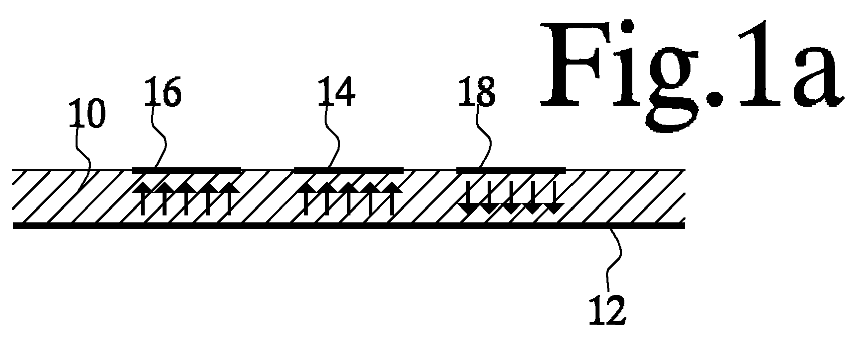
- Fig. 1a shows a cross-section of an electroacoustic balun comprising a film 10 of piezoelectric material with mutually opposite first and second surfaces, separated by a thickness of the film 10.
- the surfaces extend over the width of film (from left to right in Fig. 1a ) and the length (in the direction perpendicular to the plane of the drawing).
- the width and length of film 10 are (much) greater than the thickness of film 10.
- a common electrode 12 on the first surface of film 10 and first, second and third electrodes 14, 16, 18 are provided on the second surface.
- First electrode 14 is flanked symmetrically on either side by second and third electrode 16, 18.
- the interface between first electrode 14 and second electrode 16 i.e. the region on the surface of film 10 between the facing edges of these electrodes, has the same geometrical shape as the interface between first electrode 14 and third electrode 18.
- Fig. 1b shows a top view of the balun, with first, second and third electrodes 14, 16, 18 extending transverse to the cross-section of Fig. 1a (indicated by a dashed line in Fig. 1b ).
- Fig. 1a also shows the piezoelectric polarization direction of film 10, by means of arrows. The direction is shown only underneath the electrodes. In principle any polarization direction or unpolarized material may be used in film 10 in regions between the electrodes. The direction in these regions is omitted for clarity.
- the piezoelectric polarization direction of film 10 is position dependent. Techniques for manufacturing films with position dependent polarization are known per se. As is known per se, the piezoelectric polarization direction of piezoelectric material determines the relation between electric fields and deformations of the film.
- the polarization direction of film 10 is directed from common electrode 12 to first and second electrode 14, 16 respectively.
- the polarization direction of film 10 is directed oppositely, from third electrode 18 to common electrode 12.
- the geometric shape of the interface between the polarized regions of the first electrode 14 and the second electrode 16, i.e. of the facing edges of these regions and the relative positions of these edge is the same as the geometric shape of interface between the polarized regions for the first electrode 14 and third electrode 18.
- Fig. 2 shows a black box model of the balun, with a ground connection coupled to common electrode 12 and a first and second interface side, for single sided signals relative to ground and for symmetric signals one mutually opposite side of ground respectively.
- the first interface side has one terminal, connected to first electrode 14.
- the second interface side has two terminals, connected to second and third electrode 16, 18.
- the first interface side may be used as input for a single sided signal for example, in order to produce a differential signal on the second interface side.
- the device may also be used in reciprocally, using the second interface side as input and the first interface side as output.
- an AC electric voltage is applied between first electrode 14 and common electrode 12 in an overlap area of film 10 where first electrode 14 and common electrode 12 overlap.
- These oscillating displacements occur mainly in the overlap area of film 10, with an amplitude that gradually decays outside the overlap area with distance from the overlap area.
- the device may comprise a signal generator (not shown) coupled to the electrodes to generate and supply the AC electric voltage.
- measures may be taken to prevent or reduce leakage of vibration energy outside film.
- measures are known per se.
- a cavity may be provided between a substrate (not shown) that supports file in the area of the electrodes.
- an acoustically reflective layer structure (not shown) may be realized between the bulk of the substrate and film 10.
- Film 10 between first electrode 14 and common electrode 12 typically behaves as a first resonator, based on acoustic waves trapped in the film between the electrodes, with a resonance frequency determined by the thickness of film 10.
- the resonance frequency may also be affected by electrodes 12, 14 (16,18) and other layers in the layer stack, if present.
- film 10 between second electrode 16 and common electrode 12 behaves as a second resonator and film 10 between second electrode 16 and common electrode 12 behaves as a third resonator. Because the same film 10 is used in each of these resonators, the resonance frequencies of these resonances can easily be matched and frequency matching is independent of overall film thickness. Other factors that affect the resonance frequency, if any, can be matched by means of layout design. This should be contrasted with the case of matching resonators at different vertical positions, which depends on the relation between thicknesses of different layers.
- the frequency of the applied AC voltages is taken at or near a resonance frequency of the resonators. This results in optimal coupling.
- the resonant behavior may be used to realize a frequency selective filter operation.
- the device may comprise a signal generator (not shown) configured to generate an AC electric voltage at this frequency.
- the signal generator may be coupled to the electrodes to supply the AC electric voltage.
- common electrode 12 has been shown, extending over the area of film 10 that is covered by all of first, second and third electrode 14, 16, 18, it should be appreciated that common electrode 12 may be split into parts that face respective ones of first, second and third electrode 14, 16, 18, or parts of these electrodes. Also, although one first electrode 14, one second electrode 16 and one third electrode 18 are shown, it should be appreciated that a plurality of such electrodes may be used, for example in an interdigitated pattern.
- Figs. 3a and 3b show a part of a repetitive pattern of this type by way of example. All second electrodes 46 from the repetition may be electrically connected. Similarly, all third electrodes 48 from the repetition may be electrically connected. Although a repetition of the pattern ⁇ second electrode 16, first electrode 14, third electrode 18, first electrode 14> is shown, it should be appreciated that other repetition patterns may be used.
- the geometry has a symmetry that maps second electrodes 16 onto third electrodes 18, with inverted polarization and vice versa and that maps first electrode 14 onto first electrodes 14. A mirror symmetry may be used for example.
- Other examples include a pattern ⁇ second electrode 16, first electrode 14, second electrode 16, first electrode 14, third electrode 18, first electrode 14, third electrode 18, first electrode 14> or of the pattern ⁇ first electrode 14, second electrode 16, third electrode 18> etc.
- Fig. 4 shows a cross-section of an electroacoustic balun of another embodiment, wherein four electrodes 44a,b, 46, 48 are provided on one surface of film 10 opposite a common electrode 12 on the opposite surface of film 10.
- Two first electrodes 44a,b are provided and between first electrodes 44a,b a second electrode 46 and a third electrode 48 are provided, so that the geometry is mirror symmetric about a symmetry axis between second electrode 46 and third electrode 48.
- the first electrodes may be coupled electrically to each other so that they will carry the same electric potential.
- the polarization of film 10 has a first direction perpendicular to the surface of film 10 from common electrode 12 to a first one of first electrodes 44a, second electrode 46 and third electrode 46.
- the polarization of film 10 has a second direction perpendicular to the surface of film 10 from a second one of first electrodes 44b to common electrode 12.
- the first and second directions are mutually opposite.
- the geometrical shape of the interface between the second electrode 46 and its adjacent first electrode 44a identical to the geometrical shape of the interface between the third electrode 48 and its adjacent first electrode 44b.
- this device has a large region underneath first electrode 42 and second and third electrode where the polarization direction need not change. This simplifies the layout of the polarization.
- an AC voltage is applied between first electrodes 44a,b on one hand and common electrode 12 on the other hand. Due to the piezoelectric effect this results in oscillating displacement of the material of film 10, with a decaying amplitude outside the overlap area between first electrodes 44a,b and common electrode 12. Some oscillating displacement also occurs in further overlap areas, between common electrode 12 and second and third electrode 46, 48 respectively. Due to the piezoelectric polarization of film 10 this results in voltages between common electrode 12 and second and third electrode 46, 48 respectively.
- balun operation is realized.
- the resulting displacement profile is substantially anti-symmetric with respect to a mirror axis.
- the displacement pattern at first electrode 44a corresponds to compression in film 10 at time points when the displacement at second electrode 44b corresponds to expansion, and vice versa. This is because the polarization at 44a and 44b is opposite.
- Such a profile leads to opposite voltages at second and third electrodes 46, 48 relative to the common electrode 12, corresponding to balun operation.
- the electrodes are shaped geometrically so that the acoustic mode amplitudes are similar at the interfaces.
- Identically shape first electrodes 44a,b, or symmetrically shaped first electrodes 14 may be used to ensure this.
- the shape of the second and third electrodes is preferably selected to be the same, with identically related edges of the second and third electrodes facing the first electrode or electrodes.
- Film 10 may be manufactured for example by deposition techniques during a manufacturing process that comprises several deposition steps and optional patterning steps (photolithographic patterning may be used), which may be use to define the electrodes.
- film 10 is a layer that may be combined with other layers in the same device.
- the thickness of film 10, i.e. the distance between the larger surfaces on which the electrodes are provided may be selected dependent on the desired resonance frequency.
- polarization perpendicular to the plane of film 10 any polarization direction transverse to the surface may be used (transverse, i.e. not parallel to it and preferably deviating not more than forty five degrees from the perpendicular).
- Transverse i.e. not parallel to it and preferably deviating not more than forty five degrees from the perpendicular.
- Mutually opposite perpendicular polarization components of transverse polarization are sufficient to realize opposite voltages.
- Polarization perpendicular to the film is preferred as it results in maximum voltages.
- polarization component in a direction refers to the projection of the polarization vector on that direction. It does not exclude that this polarization component is the only component, constituting the entire polarization.
- the first electrode could be ring shaped and the second and third electrode could be realized as half rings concentric with the ring shape of the first electrode, e.g. both inside the ring of the first electrode, or outside said ring. In the latter case the first electrode may also be disc shaped. Circular rings may be used, or other shapes such as elliptically shaped rings.
- the interface between the first electrode and the second electrode can thus easily be given an identical geometric shape as the interface between the first electrode and the third electrode.
- shapes other than rings may be used.
- the elongated rectangular shapes have the advantage that they are easy to construct, have simple resonance mode shapes and provide large uniform interfaces between the electrodes.
- a computer program may be stored/distributed on a suitable medium, such as an optical storage medium or a solid-state medium supplied together with or as part of other hardware, but may also be distributed in other forms, such as via the Internet or other wired or wireless telecommunication systems. Any reference signs in the claims should not be construed as limiting the scope.
Landscapes
- Physics & Mathematics (AREA)
- Acoustics & Sound (AREA)
- Chemical & Material Sciences (AREA)
- Crystallography & Structural Chemistry (AREA)
- Piezo-Electric Transducers For Audible Bands (AREA)
- Piezo-Electric Or Mechanical Vibrators, Or Delay Or Filter Circuits (AREA)
Abstract
Description
- The invention relates to a device that comprises an electroacoustic balun.
- An electroacoustic balun device is known from
US patent No 7,091,649 . The balun comprises two stacks, each with two resonant piezoelectric layers, one above the other, with electrodes in the stack on either side of each layer. In operation voltages are applied between the electrodes of the resonator in a first one of the piezoelectric layers. This results in acoustic vibrations in the resonator in the first piezoelectric layer, which are coupled to the second one of the piezoelectric layers so that vibrations also occur in the second piezoelectric layer. Due to the piezoelectric effect this in turn results in a voltage across the electrodes of the second piezoelectric layer. -
US patent No 7,091,649 describes a device with two of such stacks, using separate electrodes. In operation voltages are applied between the electrodes of the resonators of both stacks in the first piezoelectric layer, to produce voltages between the electrodes of the resonators in the second piezoelectric layer. The polarization of the piezoelectric layers is set differently in the different stacks, in order to create a phase relation between the resulting voltages from the resonators in the second layer so that the series connection of these resonators produces twice the voltage applied to the series connection of the resonators in the first layer. Thus balun functionality can be realized. - Polarization differences in a piezoelectric layer have also been used for other purposes.
US 3,018,415 discloses a resonator comprising a piezoelectric crystal with two electrodes on respective sides of the crystal. In order to suppress undesirable vibration modes at least one of the electrodes is shaped into a central disc and a surrounding ring, and the polarization of the crystal is set in mutually opposite directions below the disc and the ring respectively. -
US 5,576,590 discloses an electroacoustic transformer with a driver part and a generator part. The transformer comprises a piezoelectric plate. In the driver part electrodes are attached on mutually opposite sides of the plate to excite acoustic vibrations. These vibrations travel outward from the driver part as an acoustic wave with longitudinal polarization (i.e. with vibrating movement in the direction of propagation in the plane of the plate). The generator part comprises electrodes at different positions on the plate. In the generator part the plate is polarized between these positions, in order to convert the waves into electric fields in the plane of the plate between the electrodes. -
US 6,448,695 discloses a frequency bandpass filter that is formed using a series arrangement of acoustic resonators. Coupling between the resonators is realized acoustically rather than electronically, by means of lateral wave coupling. - Among others, it is an object to provide for an electroacoustic balun that is easy to manufacture.
- A device according to claim 1 is provided, which comprises an electroacoustic balun. Herein at least three electrodes are provided on the same surface of a film, which may act as terminals of the balun. The edges of the electrodes face each other in two identical interfaces. The directions of the components of piezoelectric polarization perpendicular to the film are the same underneath the electrodes of one interface. Underneath the electrodes of the other interface the directions of these components are mutually opposite. Thus a single piezoelectric film is sufficient to form the acoustic part of a balun. When resonant operation is used, the use of the same film makes it easy to match the resonance frequencies.
- In an embodiment the interfaces are realized between a first electrode and separate second electrodes. Thus only three electrodes are required, which provides for a compact design. In a further embodiment the first electrode has a mirror symmetric shape, with the second electrodes facing edges of the first electrode that are related by a symmetry transformation. Thus, coupling to the second electrodes can be easily matched.
- In another embodiment two first electrodes are used on the surface of the film, electrically connected to each other, each with an interface to a respective second electrode. The second electrodes are located between the first electrodes. In this way further coupling from the second electrodes can be easily avoided. In a further embodiment, the first electrodes have identical shape. This makes it easy to improve matching of resonance frequencies. In another embodiment the polarization components underneath the two first electrodes have mutually opposite directions. In this way a large region with the same polarization direction can be used underneath the other first electrode and the second electrodes.
- In a further embodiment the second electrodes have identical shapes. This makes it easy to improve matching of resonance frequencies. In another embodiment a common electrode is used on the surface opposite the first and second electrodes, having overlaps with the first and second electrodes. Alternatively, separate electrodes may be used on that surface. The use of a common electrode makes it possible to realize a simple structure with little or no height variations.
- These and other objects and advantageous aspects will become apparent from a description of exemplary embodiments, using the following Figures.
-
Fig. 1a shows a cross-section of an electroacoustic balun -
Fig. 1b shows a top view of an electroacoustic balun -
Fig. 2 shows a black box circuit element -
Figs. 3a, b shows a an electroacoustic balun with repeating electrodes -
Fig. 4 shows a cross-section of an electroacoustic balun -
Fig. 1a shows a cross-section of an electroacoustic balun comprising afilm 10 of piezoelectric material with mutually opposite first and second surfaces, separated by a thickness of thefilm 10. The surfaces extend over the width of film (from left to right inFig. 1a ) and the length (in the direction perpendicular to the plane of the drawing). Typically, the width and length offilm 10 are (much) greater than the thickness offilm 10. - A
common electrode 12 on the first surface offilm 10 and first, second andthird electrodes First electrode 14 is flanked symmetrically on either side by second andthird electrode first electrode 14 andsecond electrode 16, i.e. the region on the surface offilm 10 between the facing edges of these electrodes, has the same geometrical shape as the interface betweenfirst electrode 14 andthird electrode 18. -
Fig. 1b shows a top view of the balun, with first, second andthird electrodes Fig. 1a (indicated by a dashed line inFig. 1b ). -
Fig. 1a also shows the piezoelectric polarization direction offilm 10, by means of arrows. The direction is shown only underneath the electrodes. In principle any polarization direction or unpolarized material may be used infilm 10 in regions between the electrodes. The direction in these regions is omitted for clarity. The piezoelectric polarization direction offilm 10 is position dependent. Techniques for manufacturing films with position dependent polarization are known per se. As is known per se, the piezoelectric polarization direction of piezoelectric material determines the relation between electric fields and deformations of the film. When an electric field is applied in a first predetermined direction parallel to the direction of polarization the piezoelectric material is compressed along that direction and when the electric field is applied in the opposite direction the piezoelectric material expands. Vice versa, expansion and compression along the direction of polarization result in mutually opposite electric fields parallel to that direction. - Between
common electrode 12 and first andsecond electrode film 10 is directed fromcommon electrode 12 to first andsecond electrode common electrode 12 andthird electrode 18 the polarization direction offilm 10 is directed oppositely, fromthird electrode 18 tocommon electrode 12. Except for these direction differences, the geometric shape of the interface between the polarized regions of thefirst electrode 14 and thesecond electrode 16, i.e. of the facing edges of these regions and the relative positions of these edge, is the same as the geometric shape of interface between the polarized regions for thefirst electrode 14 andthird electrode 18. -
Fig. 2 shows a black box model of the balun, with a ground connection coupled tocommon electrode 12 and a first and second interface side, for single sided signals relative to ground and for symmetric signals one mutually opposite side of ground respectively. The first interface side has one terminal, connected tofirst electrode 14. The second interface side has two terminals, connected to second andthird electrode - In an example of operation, an AC electric voltage is applied between
first electrode 14 andcommon electrode 12 in an overlap area offilm 10 wherefirst electrode 14 andcommon electrode 12 overlap. This results in vibration of the material offilm 10, with oscillating displacements in a direction fromfirst electrode 14 tocommon electrode 12, perpendicular to the plane of the film. These oscillating displacements occur mainly in the overlap area offilm 10, with an amplitude that gradually decays outside the overlap area with distance from the overlap area. The device may comprise a signal generator (not shown) coupled to the electrodes to generate and supply the AC electric voltage. - Due to the gradual decay some oscillating displacement in
film 10 occurs in further overlap areas, ofcommon electrode 12 with second andthird electrode film 10 in these further overlap areas, these oscillating displacements result in electric voltages betweencommon electrode 12 and second andthird electrode film 10 adjacent second andthird electrode second electrode 16 tocommon electrode 12 is opposite to the voltage difference fromthird electrode 18 tocommon electrode 12. Because the interfaces fromfirst electrode 14 to second and third electrode are geometrically identical (same distance between the edges of the electrodes, same interface length), the size of these voltages is substantially the same. Relative to each other second andthird electrodes common electrode 12. Thus, one form of balun functionality, i.e. conversion from unbalanced to balanced signals, is realized. - In an embodiment measures may be taken to prevent or reduce leakage of vibration energy outside film. Such measures are known per se. Thus for example a cavity (not shown) may be provided between a substrate (not shown) that supports file in the area of the electrodes. In another embodiment an acoustically reflective layer structure (not shown) may be realized between the bulk of the substrate and
film 10. -
Film 10 betweenfirst electrode 14 andcommon electrode 12 typically behaves as a first resonator, based on acoustic waves trapped in the film between the electrodes, with a resonance frequency determined by the thickness offilm 10. The resonance frequency may also be affected byelectrodes 12, 14 (16,18) and other layers in the layer stack, if present. Similarly,film 10 betweensecond electrode 16 andcommon electrode 12 behaves as a second resonator andfilm 10 betweensecond electrode 16 andcommon electrode 12 behaves as a third resonator. Because thesame film 10 is used in each of these resonators, the resonance frequencies of these resonances can easily be matched and frequency matching is independent of overall film thickness. Other factors that affect the resonance frequency, if any, can be matched by means of layout design. This should be contrasted with the case of matching resonators at different vertical positions, which depends on the relation between thicknesses of different layers. - Preferably the frequency of the applied AC voltages is taken at or near a resonance frequency of the resonators. This results in optimal coupling. Moreover the resonant behavior may be used to realize a frequency selective filter operation. The device may comprise a signal generator (not shown) configured to generate an AC electric voltage at this frequency. The signal generator may be coupled to the electrodes to supply the AC electric voltage.
- Although one form of operation has been described by way of example, it should be appreciated that other forms of operation may be used. For example, mutually opposite voltages may be applied to second and
third electrodes common electrode 12 to obtain a single ended voltage atfirst electrode 14 relative tocommon electrode 12. In this way, conversion from balanced to unbalanced signals with strong common-mode rejection, which is one form of balun functionality, is realized. A combination of application of voltages tofirst electrode 14 and to second andthird electrodes - Furthermore, although one
common electrode 12 has been shown, extending over the area offilm 10 that is covered by all of first, second andthird electrode common electrode 12 may be split into parts that face respective ones of first, second andthird electrode first electrode 14, onesecond electrode 16 and onethird electrode 18 are shown, it should be appreciated that a plurality of such electrodes may be used, for example in an interdigitated pattern. -
Figs. 3a and 3b show a part of a repetitive pattern of this type by way of example. Allsecond electrodes 46 from the repetition may be electrically connected. Similarly, allthird electrodes 48 from the repetition may be electrically connected. Although a repetition of the pattern <second electrode 16,first electrode 14,third electrode 18,first electrode 14> is shown, it should be appreciated that other repetition patterns may be used. Preferably the geometry has a symmetry that mapssecond electrodes 16 ontothird electrodes 18, with inverted polarization and vice versa and that mapsfirst electrode 14 ontofirst electrodes 14. A mirror symmetry may be used for example. Other examples include a pattern <second electrode 16,first electrode 14,second electrode 16,first electrode 14,third electrode 18,first electrode 14,third electrode 18,first electrode 14> or of the pattern <first electrode 14,second electrode 16,third electrode 18> etc. -
Fig. 4 shows a cross-section of an electroacoustic balun of another embodiment, wherein fourelectrodes 44a,b, 46, 48 are provided on one surface offilm 10 opposite acommon electrode 12 on the opposite surface offilm 10. Twofirst electrodes 44a,b are provided and betweenfirst electrodes 44a,b asecond electrode 46 and athird electrode 48 are provided, so that the geometry is mirror symmetric about a symmetry axis betweensecond electrode 46 andthird electrode 48. The first electrodes may be coupled electrically to each other so that they will carry the same electric potential. The polarization offilm 10 has a first direction perpendicular to the surface offilm 10 fromcommon electrode 12 to a first one offirst electrodes 44a,second electrode 46 andthird electrode 46. The polarization offilm 10 has a second direction perpendicular to the surface offilm 10 from a second one offirst electrodes 44b tocommon electrode 12. The first and second directions are mutually opposite. The geometrical shape of the interface between thesecond electrode 46 and its adjacentfirst electrode 44a identical to the geometrical shape of the interface between thethird electrode 48 and its adjacentfirst electrode 44b. As may be noted this device has a large region underneath first electrode 42 and second and third electrode where the polarization direction need not change. This simplifies the layout of the polarization. - In an example of operation an AC voltage is applied between
first electrodes 44a,b on one hand andcommon electrode 12 on the other hand. Due to the piezoelectric effect this results in oscillating displacement of the material offilm 10, with a decaying amplitude outside the overlap area betweenfirst electrodes 44a,b andcommon electrode 12. Some oscillating displacement also occurs in further overlap areas, betweencommon electrode 12 and second andthird electrode film 10 this results in voltages betweencommon electrode 12 and second andthird electrode second electrode 46 and its closestfirst electrode 44a are equal, whereas the polarizations underneaththird electrode 48 and its closestfirst electrode 44b are different, the voltages at second andthird electrode common electrode 12 are mutually opposite. Thus balun operation is realized. - It can be seen that the resulting displacement profile is substantially anti-symmetric with respect to a mirror axis. The displacement pattern at
first electrode 44a corresponds to compression infilm 10 at time points when the displacement atsecond electrode 44b corresponds to expansion, and vice versa. This is because the polarization at 44a and 44b is opposite. Such a profile leads to opposite voltages at second andthird electrodes common electrode 12, corresponding to balun operation. - It should be appreciated that this effect can be achieved in different ways. A similar effect is achieved as long as the there is a polarization change in one of the second-closest first electrode pair and the third-closest first electrode pairs. A repetition of the pattern electrodes may be used (a repetition of <
first electrode 44a (=first electrode 44b of previous repetition),second electrode 46,third electrode 48> may be used, even and odd repetitions having mutually opposite piezoelectric polarity patterns. Allsecond electrodes 46 from the repetition may be electrically connected. Similarly, allthird electrodes 48 from the repetition may be electrically connected. In a further embodiment, the sequence of the second andthird electrode - The substantial similarity of the geometrical shapes of the interfaces between electrode pairs provides for symmetric, equal sized voltages at the second and third electrodes. Interfaces are said to be geometrically identical even if they differ by a mirror symmetry, or a rotation symmetry. Obviously insubstantial differences between the interface shapes that do not result in substantial voltage size differences may be acceptable.
- The equality of the size of the voltages may also be influenced by the acoustic mode shapes in the electrodes, although the effect of the shape may be small because modes with displacement of film material perpendicular to the film surface is used. Preferably, the electrodes are shaped geometrically so that the acoustic mode amplitudes are similar at the interfaces. Identically shape
first electrodes 44a,b, or symmetrically shaped first electrodes 14 (with symmetrically related edges facing the second and third electrodes) may be used to ensure this. Similarly, the shape of the second and third electrodes is preferably selected to be the same, with identically related edges of the second and third electrodes facing the first electrode or electrodes. -
Film 10 may be manufactured for example by deposition techniques during a manufacturing process that comprises several deposition steps and optional patterning steps (photolithographic patterning may be used), which may be use to define the electrodes. In thiscase film 10 is a layer that may be combined with other layers in the same device. The thickness offilm 10, i.e. the distance between the larger surfaces on which the electrodes are provided may be selected dependent on the desired resonance frequency. - Although embodiments have been shown with polarizations perpendicular to the plane of
film 10, it should be appreciated that any polarization direction transverse to the surface may be used (transverse, i.e. not parallel to it and preferably deviating not more than forty five degrees from the perpendicular). Mutually opposite perpendicular polarization components of transverse polarization are sufficient to realize opposite voltages. Polarization perpendicular to the film is preferred as it results in maximum voltages. As used herein "polarization component" in a direction refers to the projection of the polarization vector on that direction. It does not exclude that this polarization component is the only component, constituting the entire polarization. - Although an embodiment has been shown wherein all electrodes at least partly have an elongated rectangular shape, it should be appreciated that other shapes may be used. For example the first electrode could be ring shaped and the second and third electrode could be realized as half rings concentric with the ring shape of the first electrode, e.g. both inside the ring of the first electrode, or outside said ring. In the latter case the first electrode may also be disc shaped. Circular rings may be used, or other shapes such as elliptically shaped rings. The interface between the first electrode and the second electrode can thus easily be given an identical geometric shape as the interface between the first electrode and the third electrode. Also, shapes other than rings may be used. The elongated rectangular shapes have the advantage that they are easy to construct, have simple resonance mode shapes and provide large uniform interfaces between the electrodes.
- Although embodiments have been shown wherein homogeneous regions the polarization extend underneath all of each electrode, which reduces the output impedance, it should be appreciated that the regions need extend only under part of the electrodes, preferably including a region at least extending to the edges of the electrodes where the electrodes face each other.
- It should be appreciated that additional features, not shown in the Figures may be present in practical devices. Such features may include additional layers for mass loading, adhesion between layers, frequency tuning etc. In an embodiment wherein solidly mounted resonators are used, additional features may be present to prevent acoustic leakage to the substrate. As such features are not needed to understand the present device and they are known per se from the prior art, these features have not been shown in the Figures, although of course they may also be present in the exemplary embodiments.
- Other variations to the disclosed embodiments can be understood and effected by those skilled in the art in practicing the claimed invention, from a study of the drawings, the disclosure, and the appended claims. In the claims, the word "comprising" does not exclude other elements or steps, and the indefinite article "a" or "an" does not exclude a plurality. A single processor or other unit may fulfill the functions of several items recited in the claims. The mere fact that certain measures are recited in mutually different dependent claims does not indicate that a combination of these measured cannot be used to advantage. A computer program may be stored/distributed on a suitable medium, such as an optical storage medium or a solid-state medium supplied together with or as part of other hardware, but may also be distributed in other forms, such as via the Internet or other wired or wireless telecommunication systems. Any reference signs in the claims should not be construed as limiting the scope.
Claims (11)
- A device comprising an electroacoustic balun, the device comprising:- a film (10) of piezoelectric material having a first and second surface separated by a thickness of the film (10);- a first and second pair of electrodes (14, 16, 18, 44a,b, 46, 48) on the first surface, each pair comprising a first electrode (14, 44a,b) and a second electrode (16, 18, 46, 48) defining an interface between the edges of the first electrode (14, 44a,b) and the second electrode (16, 17, 46, 48) in the pair, the first electrode (14, 44a,b) of the first and second pair being electrically connected to each other or shared by the first and second pair, the interfaces of the first and second pair being shaped geometrically identical to each other;- an electrode arrangement (12) on the second surface, the electrode arrangement (12) having at least partial overlaps with all of the electrodes (14, 16, 18, 44a, b, 46, 48) of the first and second pair;- piezoelectrically polarized regions in said film (10) at least in part of each of the overlaps, with piezoelectric polarization components perpendicular to the first surface, the direction of the polarization components of the regions in the overlaps with the first electrode (14, 44a) and the second electrode (16, 46) in the first pair being equal to each other, the directions of the polarization components in the overlaps with the first electrode (14, 44b) and the second electrode (18, 48) in the second pair being mutually opposite.
- A device according to claim 1, wherein the first and second pair share the first electrode (14) and wherein the second electrodes (16, 18) of the first and second pair are provided on mutually opposite sides of the shared first electrode (14) on said first surface.
- A device according to claim 2, wherein the first electrode (14) has a mirror symmetric shape and edges of the second electrodes (16, 18) of the first and second pair face mirror symmetrically related edges of the first electrode (14).
- A device according to claim 1, wherein the second electrode (46) of the first pair and the second electrode (48) of the second pair are provided both between the first electrode (44a) of the first pair and the first electrode (44b) of the second pair on the first surface.
- A device according to claim 4, wherein the first electrode (44a) of the first pair and the first electrode (44b) of the second pair have identical shape, and edges of the second electrodes (46, 48) of the first and second pair face mutually corresponding edges of the first electrode (44a) of the first pair and the first electrode (44b) of the second pair on the first surface respectively.
- A device according to claim 4, wherein the direction of the polarization components of the regions in the overlaps with the first electrodes (44a, b) of the first and second pair are mutually opposite.
- A device according to claim 1, wherein the second electrodes (16, 18, 46, 48) of the first and second pair have identical shapes.
- A device according to claim 1, wherein the electrode arrangement comprises a common electrode (12) having overlaps with all of the electrodes (14, 16, 18, 44a, b, 46, 48) of the first and second pair.
- A device according to claim 1, comprising an electronic signal supply circuit coupled to at least part of the electrodes and configured to generate an electric signal at a resonance frequency of acoustic waves in the film (10) and to supply said signal to said at least part of the electrodes.
- A method of operating a device according to claim 1, comprising:- applying an electrical signal between the electrode arrangement and the first electrodes, and/or between the second electrodes.
- A method according to claim 10, comprising applying the electrical signal at a resonance frequency of acoustic waves in the film (10).
Priority Applications (3)
| Application Number | Priority Date | Filing Date | Title |
|---|---|---|---|
| EP09156769A EP2237416A1 (en) | 2009-03-30 | 2009-03-30 | Device comprising an electroacoustic balun |
| US12/542,544 US8138855B2 (en) | 2009-03-30 | 2009-08-17 | Device with an electroacoustic balun |
| PCT/IB2010/051364 WO2010113106A1 (en) | 2009-03-30 | 2010-03-30 | A device with an electroacoustic balun |
Applications Claiming Priority (1)
| Application Number | Priority Date | Filing Date | Title |
|---|---|---|---|
| EP09156769A EP2237416A1 (en) | 2009-03-30 | 2009-03-30 | Device comprising an electroacoustic balun |
Publications (1)
| Publication Number | Publication Date |
|---|---|
| EP2237416A1 true EP2237416A1 (en) | 2010-10-06 |
Family
ID=40826990
Family Applications (1)
| Application Number | Title | Priority Date | Filing Date |
|---|---|---|---|
| EP09156769A Withdrawn EP2237416A1 (en) | 2009-03-30 | 2009-03-30 | Device comprising an electroacoustic balun |
Country Status (3)
| Country | Link |
|---|---|
| US (1) | US8138855B2 (en) |
| EP (1) | EP2237416A1 (en) |
| WO (1) | WO2010113106A1 (en) |
Families Citing this family (2)
| Publication number | Priority date | Publication date | Assignee | Title |
|---|---|---|---|---|
| EP2299593A1 (en) | 2009-09-18 | 2011-03-23 | Nxp B.V. | Laterally coupled bulk acoustic wave device |
| US10790801B2 (en) | 2018-09-07 | 2020-09-29 | Vtt Technical Research Centre Of Finland Ltd | Loaded resonators for adjusting frequency response of acoustic wave resonators |
Citations (7)
| Publication number | Priority date | Publication date | Assignee | Title |
|---|---|---|---|---|
| US3018415A (en) | 1956-12-31 | 1962-01-23 | R T & E Corp | Circuit recloser |
| JPS6070814A (en) * | 1983-09-27 | 1985-04-22 | Murata Mfg Co Ltd | Piezoelectric element |
| JPS60150310A (en) * | 1984-01-17 | 1985-08-08 | Tdk Corp | Piezoelectric vibrator |
| US4633204A (en) * | 1984-08-29 | 1986-12-30 | Fujitsu Limited | Mechanical filter |
| US5576590A (en) | 1994-07-26 | 1996-11-19 | Nec Corporation | Piezoelectric ceramic transformer |
| US6448695B2 (en) | 2000-06-20 | 2002-09-10 | Koninklijke Philips Electronics N.V. | Bulk acoustic wave device |
| US7091649B2 (en) | 2003-10-30 | 2006-08-15 | Avago Technologies Wireless Ip (Singapore) Pte. Ltd. | Film acoustically-coupled transformers with two reverse c-axis piezoelectric elements |
Family Cites Families (10)
| Publication number | Priority date | Publication date | Assignee | Title |
|---|---|---|---|---|
| US3018451A (en) * | 1958-12-04 | 1962-01-23 | Mattiat Oskar | Piezoelectric resonator with oppositely poled ring and spot |
| DE19914468C1 (en) * | 1999-03-30 | 2000-09-07 | Siemens Ag | Piezo-resonator, used as signal filter, impedance matcher and transformer of mobile telecommunications device, has pairs of interdigital electrodes of finger size less than the produced HF mechanical vibration wavelength |
| DE10149542A1 (en) * | 2001-10-08 | 2003-04-17 | Infineon Technologies Ag | BAW resonator |
| US6670866B2 (en) * | 2002-01-09 | 2003-12-30 | Nokia Corporation | Bulk acoustic wave resonator with two piezoelectric layers as balun in filters and duplexers |
| EP1365509B1 (en) * | 2002-05-16 | 2007-05-16 | TDK Corporation | Antenna duplexer |
| DE10256937B4 (en) * | 2002-12-05 | 2018-02-01 | Snaptrack, Inc. | With bulk acoustic waves working device with unbalanced / balanced wiring |
| DE10319554B4 (en) * | 2003-04-30 | 2018-05-09 | Snaptrack, Inc. | Bulk acoustic wave device with coupled resonators |
| US6963257B2 (en) * | 2004-03-19 | 2005-11-08 | Nokia Corporation | Coupled BAW resonator based duplexers |
| US7098758B2 (en) * | 2004-11-03 | 2006-08-29 | Avago Technologies Wireless Ip (Singapore) Pte. Ltd. | Acoustically coupled thin-film resonators having an electrode with a tapered edge |
| JP2007312164A (en) * | 2006-05-19 | 2007-11-29 | Hitachi Ltd | Piezoelectric thin film resonator, high frequency filter and high frequency module using the same |
-
2009
- 2009-03-30 EP EP09156769A patent/EP2237416A1/en not_active Withdrawn
- 2009-08-17 US US12/542,544 patent/US8138855B2/en not_active Expired - Fee Related
-
2010
- 2010-03-30 WO PCT/IB2010/051364 patent/WO2010113106A1/en not_active Ceased
Patent Citations (7)
| Publication number | Priority date | Publication date | Assignee | Title |
|---|---|---|---|---|
| US3018415A (en) | 1956-12-31 | 1962-01-23 | R T & E Corp | Circuit recloser |
| JPS6070814A (en) * | 1983-09-27 | 1985-04-22 | Murata Mfg Co Ltd | Piezoelectric element |
| JPS60150310A (en) * | 1984-01-17 | 1985-08-08 | Tdk Corp | Piezoelectric vibrator |
| US4633204A (en) * | 1984-08-29 | 1986-12-30 | Fujitsu Limited | Mechanical filter |
| US5576590A (en) | 1994-07-26 | 1996-11-19 | Nec Corporation | Piezoelectric ceramic transformer |
| US6448695B2 (en) | 2000-06-20 | 2002-09-10 | Koninklijke Philips Electronics N.V. | Bulk acoustic wave device |
| US7091649B2 (en) | 2003-10-30 | 2006-08-15 | Avago Technologies Wireless Ip (Singapore) Pte. Ltd. | Film acoustically-coupled transformers with two reverse c-axis piezoelectric elements |
Non-Patent Citations (1)
| Title |
|---|
| LAND C E: "Transistor oscillators employing piezoelectric ceramic feedback networks", IEEE INTERNATIONAL CONVENTION RECORD, IEEE INC. NEW YORK, US, vol. 13, 1 March 1965 (1965-03-01), pages 51 - 68, XP008090417 * |
Also Published As
| Publication number | Publication date |
|---|---|
| US8138855B2 (en) | 2012-03-20 |
| US20100244988A1 (en) | 2010-09-30 |
| WO2010113106A1 (en) | 2010-10-07 |
Similar Documents
| Publication | Publication Date | Title |
|---|---|---|
| KR100863876B1 (en) | Piezoelectric resonator structures and electrical filters | |
| EP1047189B1 (en) | Piezoelectric resonator | |
| US8179209B2 (en) | Complex resonance circuit | |
| TWI517572B (en) | Piezoelectric resonator having combined thickness and width vibrational modes | |
| JP2019208260A (en) | Method of manufacturing piezoelectric thin film element | |
| US11533042B2 (en) | Distributed-mode beam and frame resonators for high frequency timing circuits | |
| CN101069344B (en) | Thin film elastic wave resonator, filter and communication equipment using the same | |
| EP2493072A2 (en) | GT-cut quartz crystal resonator | |
| CN114301411A (en) | Bulk acoustic wave resonator and bulk acoustic wave filter | |
| JP2002164766A (en) | Vertically connected multimode piezoelectric filter | |
| EP2237416A1 (en) | Device comprising an electroacoustic balun | |
| JPH0396005A (en) | Piezoelectric thin film resonator | |
| Liu et al. | AlN Checker-mode resonators with Routing structures | |
| JP3485904B2 (en) | Sound transducer | |
| JPS58687B2 (en) | Electrical power supply | |
| US20030141945A1 (en) | Three-terminal filter using area flexural vibration mode | |
| JP2837722B2 (en) | Piezoelectric ultrasonic transducer | |
| JP3450204B2 (en) | Piezoelectric resonators and filters | |
| JPH10215140A (en) | Piezoelectric resonator and electronic component using the resonator | |
| JP2025099369A (en) | Frequency filter | |
| JPS59127413A (en) | Lithium tantalate oscillator | |
| US20050097954A1 (en) | Angular rate sensor | |
| JPH0153808B2 (en) | ||
| JPH0522068A (en) | Piezoelectric resonator | |
| JPS6065610A (en) | Surface acoustic wave two-terminal resonator |
Legal Events
| Date | Code | Title | Description |
|---|---|---|---|
| PUAI | Public reference made under article 153(3) epc to a published international application that has entered the european phase |
Free format text: ORIGINAL CODE: 0009012 |
|
| AK | Designated contracting states |
Kind code of ref document: A1 Designated state(s): AT BE BG CH CY CZ DE DK EE ES FI FR GB GR HR HU IE IS IT LI LT LU LV MC MK MT NL NO PL PT RO SE SI SK TR |
|
| AX | Request for extension of the european patent |
Extension state: AL BA RS |
|
| 17P | Request for examination filed |
Effective date: 20110406 |
|
| 17Q | First examination report despatched |
Effective date: 20110427 |
|
| AKX | Designation fees paid |
Designated state(s): AT BE BG CH CY CZ DE DK EE ES FI FR GB GR HR HU IE IS IT LI LT LU LV MC MK MT NL NO PL PT RO SE SI SK TR |
|
| STAA | Information on the status of an ep patent application or granted ep patent |
Free format text: STATUS: THE APPLICATION IS DEEMED TO BE WITHDRAWN |
|
| 18D | Application deemed to be withdrawn |
Effective date: 20131001 |