EP2237377A1 - Instrument having oblique mounted terminal posts - Google Patents
Instrument having oblique mounted terminal posts Download PDFInfo
- Publication number
- EP2237377A1 EP2237377A1 EP10158475A EP10158475A EP2237377A1 EP 2237377 A1 EP2237377 A1 EP 2237377A1 EP 10158475 A EP10158475 A EP 10158475A EP 10158475 A EP10158475 A EP 10158475A EP 2237377 A1 EP2237377 A1 EP 2237377A1
- Authority
- EP
- European Patent Office
- Prior art keywords
- instrument
- conductive terminals
- terminal
- circuit board
- terminal posts
- Prior art date
- Legal status (The legal status is an assumption and is not a legal conclusion. Google has not performed a legal analysis and makes no representation as to the accuracy of the status listed.)
- Granted
Links
Images




Classifications
-
- H—ELECTRICITY
- H01—ELECTRIC ELEMENTS
- H01R—ELECTRICALLY-CONDUCTIVE CONNECTIONS; STRUCTURAL ASSOCIATIONS OF A PLURALITY OF MUTUALLY-INSULATED ELECTRICAL CONNECTING ELEMENTS; COUPLING DEVICES; CURRENT COLLECTORS
- H01R24/00—Two-part coupling devices, or either of their cooperating parts, characterised by their overall structure
- H01R24/76—Two-part coupling devices, or either of their cooperating parts, characterised by their overall structure with sockets, clips or analogous contacts and secured to apparatus or structure, e.g. to a wall
-
- H—ELECTRICITY
- H05—ELECTRIC TECHNIQUES NOT OTHERWISE PROVIDED FOR
- H05K—PRINTED CIRCUITS; CASINGS OR CONSTRUCTIONAL DETAILS OF ELECTRIC APPARATUS; MANUFACTURE OF ASSEMBLAGES OF ELECTRICAL COMPONENTS
- H05K5/00—Casings, cabinets or drawers for electric apparatus
- H05K5/02—Details
- H05K5/0247—Electrical details of casings, e.g. terminals, passages for cables or wiring
-
- H—ELECTRICITY
- H01—ELECTRIC ELEMENTS
- H01R—ELECTRICALLY-CONDUCTIVE CONNECTIONS; STRUCTURAL ASSOCIATIONS OF A PLURALITY OF MUTUALLY-INSULATED ELECTRICAL CONNECTING ELEMENTS; COUPLING DEVICES; CURRENT COLLECTORS
- H01R2101/00—One pole
-
- H—ELECTRICITY
- H01—ELECTRIC ELEMENTS
- H01R—ELECTRICALLY-CONDUCTIVE CONNECTIONS; STRUCTURAL ASSOCIATIONS OF A PLURALITY OF MUTUALLY-INSULATED ELECTRICAL CONNECTING ELEMENTS; COUPLING DEVICES; CURRENT COLLECTORS
- H01R2201/00—Connectors or connections adapted for particular applications
- H01R2201/20—Connectors or connections adapted for particular applications for testing or measuring purposes
-
- Y—GENERAL TAGGING OF NEW TECHNOLOGICAL DEVELOPMENTS; GENERAL TAGGING OF CROSS-SECTIONAL TECHNOLOGIES SPANNING OVER SEVERAL SECTIONS OF THE IPC; TECHNICAL SUBJECTS COVERED BY FORMER USPC CROSS-REFERENCE ART COLLECTIONS [XRACs] AND DIGESTS
- Y10—TECHNICAL SUBJECTS COVERED BY FORMER USPC
- Y10S—TECHNICAL SUBJECTS COVERED BY FORMER USPC CROSS-REFERENCE ART COLLECTIONS [XRACs] AND DIGESTS
- Y10S439/00—Electrical connectors
- Y10S439/954—Special orientation of electrical connector
Definitions
- Embodiments of the present invention are directed toward test, measurement, and calibration instruments having at least one terminal post.
- Test, measurement, and calibration instruments have input/output (I/O) ports to couple the instrument to an external electrical device.
- I/O port includes a terminal or binding post which electrically couples a connector of an external device to the I/O port of the instrument.
- terminal posts are versatile, and in many cases may accept banana plugs, alligator clips, bare wires, spade lugs, fork connectors, and other electrical connectors.
- terminal posts are arranged together on a panel of the test instrument. Due to space limitations many terminal posts are arranged in close proximity with each other.
- a panel 110 of an instrument 100 such as a calibration instrument, having a conventional terminal post configuration is shown in Figure 1 .
- the panel 110 has a plurality of terminal posts 101 arranged on it.
- the terminal posts 101 protrude out from the panel 110 of the instrument 100 so that a longitudinal axis of each terminal post 101 is approximately perpendicular with the panel 110 of the instrument 100.
- Connectors 102 in this example spade lugs, are coupled to a respective one of the terminal posts 101 to electrically connect an external device to the instrument 100 through a test lead or wire 103 that is coupled to the connector 102.
- a rigid portion of the wire extends from a side of the terminal post and often runs into adjacent terminal posts.
- wire 103a is coupled to connector 102a.
- the connector 102a is clamped by the terminal post 101 a such that the wire 103a extends from a side of the terminal post 101 a and runs into adjacent terminal post 101 b.
- terminal posts attaching a connector to a terminal post can be very difficult, particularly when the terminal posts are located in close proximity with one another. Additionally, when the terminal posts are arranged on an instrument too close together, the rigid part of the wire that runs into adjacent terminal posts may prevent the connector from making good electrical contact or make unwanted contact with an adjacent terminal. Furthermore, the rigid part of the wire can wear out prematurely due to excessive strain caused by bending around adjacent terminal posts. Due to the above mentioned problems, terminal posts generally require a fair amount of space on the panel of the instrument so that a user has enough space to properly install a connector and prevent the premature wearing of the connector.
- the present invention is directed toward an instrument, such as a calibration instrument, having at least one terminal post positioned at an angle relative to a surface on the instrument.
- an instrument such as a calibration instrument
- One aspect of the invention is directed to an instrument having an outer surface and a plurality of conductive terminals coupled to the instrument.
- the conductive terminals may be coupled to the instrument such that a longitudinal axis of each of the plurality of conductive terminals are at an oblique angle relative to the outer surface.
- connection panel having a circuit board having a first surface and a plurality of conductive terminals.
- Each of the conductive terminals may have a beveled back surface.
- the beveled back surface of the conductive terminals may be mounted on the first surface of the circuit board such that a longitudinal axis of the conductive terminals is at an oblique angle relative to the first surface of the circuit board.
- Embodiments of the present invention are directed toward test, measurement, and calibration instruments having at least one binding or terminal post.
- many embodiments are directed to at least one terminal post positioned at an angle relative to a surface on the instrument.
- FIG. 2 is an isometric view of an instrument 200 according to one embodiment of the invention.
- the instrument 200 has a display and a panel 201 having an outer surface.
- a plurality of terminal posts 206 are arranged on the panel 201 in an array configuration.
- the terminal posts 206 provide electrical connection from the instrument 200 to another electrical device to be tested, calibrated, and/or measured.
- the terminal posts 206 are operable to accept a variety of connectors 210, such as banana plugs, alligator clips, bare wires, spade lugs, fork connectors or other electrical connectors.
- Each connector 210 is coupled to the electrical device through a wire or test lead 212.
- banana plugs 210a and 210b are coupled to the respective terminal post 206a and 206b.
- the terminal posts 206 in the embodiment shown in Figure 2 are arranged on the panel 201 of the instrument 200 in an array configuration. However, as will be clear to a person having ordinary skill in the art, the terminal posts 206 may be arranged on the panel of the instrument in any configuration.
- Each terminal post 206 has a first surface 208 at an end of the terminal post 206.
- the first surface 208 of each terminal post 206 is positioned such that the first surface 208 is facing the same direction.
- the terminal posts 206 project away from the instrument 200 at an oblique angle relative to the panel 201. Therefore, rather than having terminal posts 206 extending away from the panel 201 of the instrument 200 so that a longitudinal axis of the terminal post 206 is perpendicular with the panel 201 of the instrument 200, the terminal posts 206 extend away from the panel 201 of the instrument 200 so that a longitudinal axis of the terminal posts 206 are at an oblique angle relative to the panel 201.
- the longitudinal axis of the terminal posts 206 are angled between 35° and 75° relative to the panel 201. In other embodiments, the terminal posts 206 are angled between 45° and 65° relative to the panel 201. In other embodiments still, the terminal posts 206 are angled between 50° and 60° relative to the panel 201. In one embodiment the terminal posts 206 are angled approximately 55° relative to the panel 201.
- Angling the terminal posts 206 relative to the panel 201 of the instrument 200 provides more available space for each respective connector 210 and its corresponding wire 212.
- the rigid part of the wire 212a and 212b, respectively, extending from the side of the corresponding connector 206a and 206b does not run into the adjacent terminal posts 206c and 206d. Rather, the rigid part of the wires 212a and 212b extends above the adjacent terminal posts 206c and 206d.
- this arrangement of the terminal posts 206 allows the terminal posts 206 to be arranged closer together than conventional arrangements.
- the terminal posts 206 may be angled in any direction.
- the terminal posts 206 are angled such that the first surface 208 of each terminal post 206 projects in an upward direction.
- Many of the components of the instrument 300 shown in Figure 3 are used in the instrument 200 in Figure 2 . Therefore, in the interest of brevity an explanation of their structure and function will not be repeated.
- the terminal posts 206 in the instrument 300 are angled such that a first surface 208 of each terminal post 206 projects in an upward direction.
- each terminal post 206 is at an acute angle with a panel 201 of the instrument 300 just above the terminal post 206.
- the terminal posts 206 may be angled such that the first surface 208 of each terminal post 206 is angled downwardly.
- some of the terminal post 206 are angled in a first direction, while other terminal posts 206 are angled in a second direction or a plurality of different directions.
- Figure 4 is a cross sectional schematic illustration of an instrument having oblique terminal posts 206 according to one embodiment of the invention. Most of the components on Figure 4 are used in the instrument shown in Figure 2 . Therefore, in the interest of brevity, an explanation of their structure and function will not be repeated.
- Figure 4 shows an instrument 200 having a plurality of obliquely mounted terminal posts 206 arranged in an array configuration. A first row of terminal posts 206 are provided in cross section.
- Figure 5 is a schematic illustration of a top down view of the terminal posts 206 shown in cross section in Figure 4 .
- Connectors 210 in this embodiment spade lugs, are coupled to the terminal posts 206 such that a wire or test lead 212 coupled to the connector 210 projects from a side of the respective terminal post 206. As in the embodiment shown in Figure 2 , the wires 212 project from the connectors 210 so that the wires 212 extend in front of an adjacent connector 210 without running into it.
- each terminal post 206 is provided through an opening 222 in the panel 201 of the instrument 200.
- Each terminal post 206 is mounted to a circuit board 214 by a screw 216.
- a rear surface 218 of each terminal post 206 abuts a front surface 220 of the circuit board 214.
- the rear surface 218 of each of the terminal posts 206 is beveled.
- the angle of the bevel on the rear surface 218 of the terminal post 206 defines the angle in which the terminal post 206 projects from the panel 201 of the instrument 200.
- the rear surface 218 of the terminal post 206 is beveled to a 35° angle.
- the beveled rear surface 218 of the terminal post 206 abuts the front surface 220 of the circuit board 214.
- the angle of the circuit board 214 relative to the panel 201 of the instrument 200 may define or at the very least contribute to determining the angle in which the terminal posts 206 extend from the panel 201 of the instrument 200.
- the terminal posts 206 are adjustable.
- the terminal posts 206 may be adjustable so that the first surface 208 of each terminal posts 206 projects in a different direction.
- the terminal posts 206 may be adjusted so that the first surface 208 projects in a different direction, while substantially maintaining a particular acute angle of the longitudinal axis of the terminal post 206 relative to the panel 201.
- the terminal posts 206 may be coupled to the circuit board 214 such that the terminal posts 206 are rotatable relative to the circuit board 214 or the terminal posts 206, themselves, may be rotatable.
- terminal posts 206 are able to rotate a full 360 degrees. Thus, a user may be able to determine the direction in which the first surface 208 of each terminal post 206 projects.
- the instrument is a test, calibration, or measurement instrument.
Landscapes
- Engineering & Computer Science (AREA)
- Microelectronics & Electronic Packaging (AREA)
- Connections Arranged To Contact A Plurality Of Conductors (AREA)
- Coupling Device And Connection With Printed Circuit (AREA)
Abstract
Description
- Embodiments of the present invention are directed toward test, measurement, and calibration instruments having at least one terminal post.
- Test, measurement, and calibration instruments, such as multimeters, temperature calibrators and the like, have input/output (I/O) ports to couple the instrument to an external electrical device. Each I/O port includes a terminal or binding post which electrically couples a connector of an external device to the I/O port of the instrument. Typically, terminal posts are versatile, and in many cases may accept banana plugs, alligator clips, bare wires, spade lugs, fork connectors, and other electrical connectors. Often many terminal posts are arranged together on a panel of the test instrument. Due to space limitations many terminal posts are arranged in close proximity with each other.
- A
panel 110 of aninstrument 100, such as a calibration instrument, having a conventional terminal post configuration is shown inFigure 1 . Thepanel 110 has a plurality of terminal posts 101 arranged on it. The terminal posts 101 protrude out from thepanel 110 of theinstrument 100 so that a longitudinal axis of each terminal post 101 is approximately perpendicular with thepanel 110 of theinstrument 100. Connectors 102, in this example spade lugs, are coupled to a respective one of the terminal posts 101 to electrically connect an external device to theinstrument 100 through a test lead or wire 103 that is coupled to the connector 102. As can be seen inFigure 1 , a rigid portion of the wire extends from a side of the terminal post and often runs into adjacent terminal posts. For instance,wire 103a is coupled toconnector 102a. Theconnector 102a is clamped by theterminal post 101 a such that thewire 103a extends from a side of theterminal post 101 a and runs intoadjacent terminal post 101 b. - As can be seen from the Figure, attaching a connector to a terminal post can be very difficult, particularly when the terminal posts are located in close proximity with one another. Additionally, when the terminal posts are arranged on an instrument too close together, the rigid part of the wire that runs into adjacent terminal posts may prevent the connector from making good electrical contact or make unwanted contact with an adjacent terminal. Furthermore, the rigid part of the wire can wear out prematurely due to excessive strain caused by bending around adjacent terminal posts. Due to the above mentioned problems, terminal posts generally require a fair amount of space on the panel of the instrument so that a user has enough space to properly install a connector and prevent the premature wearing of the connector.
- There is, therefore, a need for a system and method of arranging terminal posts on test instruments so that attaching connectors to the terminal posts is easier. Additionally, there is a need for a system and method for allowing terminal posts to be arranged closer together while preventing the problems discussed above.
- The present invention is directed toward an instrument, such as a calibration instrument, having at least one terminal post positioned at an angle relative to a surface on the instrument. One aspect of the invention is directed to an instrument having an outer surface and a plurality of conductive terminals coupled to the instrument. The conductive terminals may be coupled to the instrument such that a longitudinal axis of each of the plurality of conductive terminals are at an oblique angle relative to the outer surface.
- Another aspect of the invention is directed to a connection panel having a circuit board having a first surface and a plurality of conductive terminals. Each of the conductive terminals may have a beveled back surface. The beveled back surface of the conductive terminals may be mounted on the first surface of the circuit board such that a longitudinal axis of the conductive terminals is at an oblique angle relative to the first surface of the circuit board.
-
- Figure 1
- is an isometric view of an instrument in accordance with prior art.
- Figure 2
- is an isometric view of an instrument according to one embodiment of the invention.
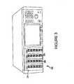
- Figure 3
- is an isometric view of an instrument according to one embodiment of the invention.
- Figure 4
- is a cross sectional schematic illustration of an instrument according to one embodiment of the invention.
- Figure 5
- is a schematic illustration of a top down view of the terminal posts shown in cross section in
Figure 4 . - Embodiments of the present invention are directed toward test, measurement, and calibration instruments having at least one binding or terminal post. In particular, many embodiments are directed to at least one terminal post positioned at an angle relative to a surface on the instrument. Certain details are set forth below to provide a sufficient understanding of the embodiments of the invention. However, it will be clear to one skilled in the art that various embodiments of the invention may be practiced without these particular details. In other instances, well known electrical circuits and signals have not been shown in detail in order to avoid unnecessarily obscuring the invention.
-
Figure 2 is an isometric view of aninstrument 200 according to one embodiment of the invention. Theinstrument 200 has a display and apanel 201 having an outer surface. A plurality ofterminal posts 206 are arranged on thepanel 201 in an array configuration. As discussed above, theterminal posts 206 provide electrical connection from theinstrument 200 to another electrical device to be tested, calibrated, and/or measured. Theterminal posts 206 are operable to accept a variety ofconnectors 210, such as banana plugs, alligator clips, bare wires, spade lugs, fork connectors or other electrical connectors. Eachconnector 210 is coupled to the electrical device through a wire ortest lead 212. For instance, in the embodiment shown,banana plugs terminal post terminal posts 206 in the embodiment shown inFigure 2 are arranged on thepanel 201 of theinstrument 200 in an array configuration. However, as will be clear to a person having ordinary skill in the art, theterminal posts 206 may be arranged on the panel of the instrument in any configuration. - Each
terminal post 206 has afirst surface 208 at an end of theterminal post 206. In the embodiment shown inFigure 2 , thefirst surface 208 of eachterminal post 206 is positioned such that thefirst surface 208 is facing the same direction. Theterminal posts 206 project away from theinstrument 200 at an oblique angle relative to thepanel 201. Therefore, rather than havingterminal posts 206 extending away from thepanel 201 of theinstrument 200 so that a longitudinal axis of theterminal post 206 is perpendicular with thepanel 201 of theinstrument 200, theterminal posts 206 extend away from thepanel 201 of theinstrument 200 so that a longitudinal axis of theterminal posts 206 are at an oblique angle relative to thepanel 201. In some embodiments, the longitudinal axis of theterminal posts 206 are angled between 35° and 75° relative to thepanel 201. In other embodiments, theterminal posts 206 are angled between 45° and 65° relative to thepanel 201. In other embodiments still, theterminal posts 206 are angled between 50° and 60° relative to thepanel 201. In one embodiment theterminal posts 206 are angled approximately 55° relative to thepanel 201. - Angling the
terminal posts 206 relative to thepanel 201 of theinstrument 200, provides more available space for eachrespective connector 210 and itscorresponding wire 212. For instance, as can be seen byconnector Figure 2 , the rigid part of thewire corresponding connector adjacent terminal posts wires adjacent terminal posts terminal posts 206 allows theterminal posts 206 to be arranged closer together than conventional arrangements. - Although the embodiment shown in
Figure 2 shows that theterminal posts 206 are angled so that thefirst surface 208 of eachterminal posts 206 projects in a particular direction, as will be clear to a person having ordinary skill in the art, theterminal posts 206 may be angled in any direction. For instance, in the embodiment shown inFigure 3 theterminal posts 206 are angled such that thefirst surface 208 of eachterminal post 206 projects in an upward direction. Many of the components of theinstrument 300 shown inFigure 3 are used in theinstrument 200 inFigure 2 . Therefore, in the interest of brevity an explanation of their structure and function will not be repeated. As indicated above, theterminal posts 206 in theinstrument 300 are angled such that afirst surface 208 of eachterminal post 206 projects in an upward direction. That is a longitudinal axis of eachterminal post 206 is at an acute angle with apanel 201 of theinstrument 300 just above theterminal post 206. In another embodiment, theterminal posts 206 may be angled such that thefirst surface 208 of eachterminal post 206 is angled downwardly. In yet another embodiment, some of theterminal post 206 are angled in a first direction, while otherterminal posts 206 are angled in a second direction or a plurality of different directions. -
Figure 4 is a cross sectional schematic illustration of an instrument having obliqueterminal posts 206 according to one embodiment of the invention. Most of the components onFigure 4 are used in the instrument shown inFigure 2 . Therefore, in the interest of brevity, an explanation of their structure and function will not be repeated.Figure 4 shows aninstrument 200 having a plurality of obliquely mountedterminal posts 206 arranged in an array configuration. A first row ofterminal posts 206 are provided in cross section.Figure 5 is a schematic illustration of a top down view of theterminal posts 206 shown in cross section inFigure 4 .Connectors 210, in this embodiment spade lugs, are coupled to theterminal posts 206 such that a wire ortest lead 212 coupled to theconnector 210 projects from a side of the respectiveterminal post 206. As in the embodiment shown inFigure 2 , thewires 212 project from theconnectors 210 so that thewires 212 extend in front of anadjacent connector 210 without running into it. - As can be best seen in
Figure 5 , a portion of eachterminal post 206 is provided through anopening 222 in thepanel 201 of theinstrument 200. Eachterminal post 206 is mounted to acircuit board 214 by ascrew 216. In particular, arear surface 218 of eachterminal post 206 abuts afront surface 220 of thecircuit board 214. In the embodiment shown inFigure 5 , therear surface 218 of each of theterminal posts 206 is beveled. In one embodiment, the angle of the bevel on therear surface 218 of theterminal post 206 defines the angle in which theterminal post 206 projects from thepanel 201 of theinstrument 200. Therefore, to obtain aterminal post 206 that is angled approximately 55° relative to thepanel 201 of theinstrument 200 or approximately 35° relative to an axis that is perpendicular to thepanel 201, therear surface 218 of theterminal post 206 is beveled to a 35° angle. Thus, the beveledrear surface 218 of theterminal post 206 abuts thefront surface 220 of thecircuit board 214. As will be clear to a person having ordinary skill in the art, the angle of thecircuit board 214 relative to thepanel 201 of theinstrument 200 may define or at the very least contribute to determining the angle in which theterminal posts 206 extend from thepanel 201 of theinstrument 200. - In some embodiments, the
terminal posts 206 are adjustable. In particular, theterminal posts 206 may be adjustable so that thefirst surface 208 of eachterminal posts 206 projects in a different direction. In one embodiment, theterminal posts 206 may be adjusted so that thefirst surface 208 projects in a different direction, while substantially maintaining a particular acute angle of the longitudinal axis of theterminal post 206 relative to thepanel 201. For instance, as will be clear to a person having ordinary skill in the art, theterminal posts 206 may be coupled to thecircuit board 214 such that theterminal posts 206 are rotatable relative to thecircuit board 214 or theterminal posts 206, themselves, may be rotatable. In one embodiment,terminal posts 206 are able to rotate a full 360 degrees. Thus, a user may be able to determine the direction in which thefirst surface 208 of eachterminal post 206 projects. - According to an embodiment, the instrument is a test, calibration, or measurement instrument.
- Although the present invention has been described with reference to the disclosed embodiments, persons skilled in the art will recognize that changes may be made in form and detail without departing from the spirit and scope of the invention. Such modifications are well within the skill of those ordinarily skilled in the art. Accordingly, the invention is not limited except as by the appended claims.
Claims (15)
- An instrument, comprising:an outer surface; anda plurality of conductive terminals coupled to the instrument such that a longitudinal axis of each of the plurality of conductive terminals are at an oblique angle relative to the outer surface.
- The instrument of claim 1 wherein the oblique angle is between 45° and 65°.
- The instrument of claim 1 or 2 wherein the oblique angle is approximately 55°.
- The instrument of one of claims 1-3 wherein the plurality of conductive terminals are at an oblique angle relative to the outer surface such that a first surface of each of the conductive terminals is facing a first direction.
- The instrument of one of claims 1-4 wherein the conductive terminals are rotatable such that when each of the conductive terminals are rotated the first surface of each of the conductive terminals are facing in a second direction, the second direction being different from the first.
- The instrument of one of claims 1-5 wherein a first surface of a first set of conductive terminals are facing a first direction and a second surface of a second set of conductive terminals are facing a second direction.
- A connection panel, comprising:a circuit board having a first surface; anda plurality of conductive terminals, each of the conductive terminals having a beveled back surface, the beveled back surface of the conductive terminals being mounted on the first surface of the circuit board such that a longitudinal axis of the conductive terminals is at an oblique angle relative to the first surface of the circuit board.
- The connection panel of claim 7 wherein the beveled back surface defines the oblique angle.
- The connection panel of claim 7 or 8 wherein the beveled back surface of each conductive terminal is at substantially the same angle.
- The connection panel of one of claims 7-9 wherein each conductive terminal is mounted on the circuit board such that a first surface of each conductive terminal projects in a first direction.
- The connection panel of one of claims 7-10 wherein each of the conductive terminals are rotatable relative to the circuit board.
- The connection panel of one of claims 7-11 wherein oblique angle is between approximately 50° and 60°.
- A method of coupling conductors to respective conductive terminals of an instrument, comprising:securing a plurality of conductive terminals to the instrument such that a longitudinal axis of each of the conductive terminals is positioned at an oblique angle relative to a face of the instrument from which the conductive terminals project; andconnecting the conductors to respective conducive terminals so that a longitudinal axis of each of the conductors is perpendicular to the longitudinal axis of a respective one of the conductive terminals and the respective longitudinal axis of at least one of the conductors projects over an outer end of at least one of the conductive terminals.
- The method of claim 13 wherein the act of securing a plurality of conductive terminals to the circuit board comprises securing a plurality of conductive terminals to the circuit board such that a longitudinal axis of each of the conductive terminals is positioned at approximately the same angle relative to the circuit board.
- The method of claim 13 or 14 wherein the conductive terminals project from the instrument at approximately between 50° and 60° relative to the face of the instrument.
Applications Claiming Priority (1)
| Application Number | Priority Date | Filing Date | Title |
|---|---|---|---|
| US12/417,500 US7922522B2 (en) | 2009-04-02 | 2009-04-02 | Instrument having oblique mounted terminal posts |
Publications (2)
| Publication Number | Publication Date |
|---|---|
| EP2237377A1 true EP2237377A1 (en) | 2010-10-06 |
| EP2237377B1 EP2237377B1 (en) | 2015-05-20 |
Family
ID=42124452
Family Applications (1)
| Application Number | Title | Priority Date | Filing Date |
|---|---|---|---|
| EP20100158475 Active EP2237377B1 (en) | 2009-04-02 | 2010-03-30 | Instrument having oblique mounted terminal posts |
Country Status (2)
| Country | Link |
|---|---|
| US (1) | US7922522B2 (en) |
| EP (1) | EP2237377B1 (en) |
Cited By (1)
| Publication number | Priority date | Publication date | Assignee | Title |
|---|---|---|---|---|
| EP3490070A1 (en) * | 2017-11-27 | 2019-05-29 | Siemens Aktiengesellschaft | Cable connection element |
Families Citing this family (1)
| Publication number | Priority date | Publication date | Assignee | Title |
|---|---|---|---|---|
| CN116481703B (en) * | 2023-04-21 | 2025-11-07 | 上海铭控传感技术有限公司 | A smart differential pressure gauge |
Citations (9)
| Publication number | Priority date | Publication date | Assignee | Title |
|---|---|---|---|---|
| GB1245905A (en) * | 1970-01-19 | 1971-09-15 | Hego Electric Gmbh | Terminal block |
| US3848958A (en) * | 1973-08-09 | 1974-11-19 | Teradyne Inc | High density terminal strip |
| DE2736620B1 (en) * | 1977-08-13 | 1978-04-06 | Weidmueller Kg C | Clamp for printed circuits |
| US4331377A (en) * | 1979-03-27 | 1982-05-25 | Webster, Ebbinghaus & Co. (Weco) | Terminal, preferably for mounting on circuit boards of printed circuits |
| DE3231690A1 (en) * | 1982-08-26 | 1984-03-01 | Phönix Elektrizitätsgesellschaft H. Knümann GmbH & Co KG, 4933 Blomberg | Electrical connecting terminal for printed-circuit boards |
| US5292263A (en) * | 1993-01-12 | 1994-03-08 | The Whitaker Corporation | Electrical connector |
| JPH09229722A (en) * | 1996-02-26 | 1997-09-05 | Yokogawa Electric Corp | Panel instrument |
| JP2003109688A (en) * | 2002-08-08 | 2003-04-11 | Yokogawa Electric Corp | Terminal block and panel instrument |
| US20080232743A1 (en) * | 2007-03-23 | 2008-09-25 | Erik Gronvall | Drop terminal with anchor block for retaining a stub cable |
Family Cites Families (17)
| Publication number | Priority date | Publication date | Assignee | Title |
|---|---|---|---|---|
| US1669209A (en) * | 1924-08-18 | 1928-05-08 | Ribaysen Jacob | Lamp socket |
| US3073891A (en) * | 1959-07-06 | 1963-01-15 | Mc Graw Edison Co | Rotatable insulating bushing |
| US5639261A (en) * | 1994-12-23 | 1997-06-17 | Lucent Technologies Inc. | Modular cross-connect system |
| USD389801S (en) * | 1996-04-10 | 1998-01-27 | Multiplex Technology, Inc. | Surface mount modular |
| US5664971A (en) * | 1996-08-01 | 1997-09-09 | Coy; John W. | Terminal binding post |
| AU133122S (en) * | 1997-02-25 | 1998-03-10 | Sony Corp | Signal converter for monitor television receiver |
| US6537106B1 (en) * | 1998-06-05 | 2003-03-25 | Adc Telecommunications, Inc. | Telecommunications patch panel with angled connector modules |
| USD421965S (en) * | 1999-05-10 | 2000-03-28 | Ditel, Inc. | Fiber optic cable connector plate |
| TW465839U (en) * | 2000-12-21 | 2001-11-21 | Hon Hai Prec Ind Co Ltd | Electrical connector |
| JP2002298952A (en) * | 2001-03-29 | 2002-10-11 | Tyco Electronics Amp Kk | Electrical connector |
| USD465216S1 (en) * | 2001-06-01 | 2002-11-05 | Lightchip, Inc. | Optical communications device housing portion |
| USD477570S1 (en) * | 2001-06-01 | 2003-07-22 | Confluent Photonics Corp. | Optical communications device housing portion |
| DE60335052D1 (en) * | 2002-07-23 | 2010-12-30 | Panasonic Elec Works Co Ltd | Low profile connector |
| JP3884346B2 (en) * | 2002-07-31 | 2007-02-21 | タイコエレクトロニクスアンプ株式会社 | Electrical connector |
| NL1021724C2 (en) * | 2002-10-23 | 2004-04-26 | Framatome Connectors Int | Cable connector assembly and system. |
| US7086866B1 (en) * | 2005-10-27 | 2006-08-08 | Molex Incorporated | Circuit board mounted electrical connector |
| US7404742B2 (en) * | 2006-12-04 | 2008-07-29 | Fluke Corporation | Method and apparatus for an electrical connector with binding posts and an RJ connector |
-
2009
- 2009-04-02 US US12/417,500 patent/US7922522B2/en active Active
-
2010
- 2010-03-30 EP EP20100158475 patent/EP2237377B1/en active Active
Patent Citations (9)
| Publication number | Priority date | Publication date | Assignee | Title |
|---|---|---|---|---|
| GB1245905A (en) * | 1970-01-19 | 1971-09-15 | Hego Electric Gmbh | Terminal block |
| US3848958A (en) * | 1973-08-09 | 1974-11-19 | Teradyne Inc | High density terminal strip |
| DE2736620B1 (en) * | 1977-08-13 | 1978-04-06 | Weidmueller Kg C | Clamp for printed circuits |
| US4331377A (en) * | 1979-03-27 | 1982-05-25 | Webster, Ebbinghaus & Co. (Weco) | Terminal, preferably for mounting on circuit boards of printed circuits |
| DE3231690A1 (en) * | 1982-08-26 | 1984-03-01 | Phönix Elektrizitätsgesellschaft H. Knümann GmbH & Co KG, 4933 Blomberg | Electrical connecting terminal for printed-circuit boards |
| US5292263A (en) * | 1993-01-12 | 1994-03-08 | The Whitaker Corporation | Electrical connector |
| JPH09229722A (en) * | 1996-02-26 | 1997-09-05 | Yokogawa Electric Corp | Panel instrument |
| JP2003109688A (en) * | 2002-08-08 | 2003-04-11 | Yokogawa Electric Corp | Terminal block and panel instrument |
| US20080232743A1 (en) * | 2007-03-23 | 2008-09-25 | Erik Gronvall | Drop terminal with anchor block for retaining a stub cable |
Cited By (2)
| Publication number | Priority date | Publication date | Assignee | Title |
|---|---|---|---|---|
| EP3490070A1 (en) * | 2017-11-27 | 2019-05-29 | Siemens Aktiengesellschaft | Cable connection element |
| US11973300B2 (en) | 2017-11-27 | 2024-04-30 | Siemens Aktiengesellschaft | Switch cabinet having a power converter having a cable connection element |
Also Published As
| Publication number | Publication date |
|---|---|
| US20100255715A1 (en) | 2010-10-07 |
| US7922522B2 (en) | 2011-04-12 |
| EP2237377B1 (en) | 2015-05-20 |
Similar Documents
| Publication | Publication Date | Title |
|---|---|---|
| US7521634B2 (en) | Multi-Channel signal acquisition probe | |
| CN100593345C (en) | Network connection detection module | |
| US7892021B2 (en) | Lumped resistance electrical cable | |
| KR100855208B1 (en) | High Performance Tester Interface Module | |
| US7674126B2 (en) | Contacts for use in monitoring connection patterns in data ports | |
| DE60219581T2 (en) | A multi-channel signal pickup with low input capacitance and pickup head | |
| CN101740896B (en) | High frequency circuit module | |
| CN101405608A (en) | Test connector, kit and method for distinguishing a group of wires from other wires of a multi-wire cable | |
| KR20070084175A (en) | Cable terminal with flexible contacts | |
| CN101685103A (en) | Probe assembly | |
| US8232814B2 (en) | Four-wire ohmmeter connector and ohmmeter using same | |
| CN113030526B (en) | Test adapter and test system | |
| KR20100122086A (en) | Test system with high frequency interposer | |
| KR20160140606A (en) | Contacting assembly, in particular an HF measuring tip | |
| JPH0812209B2 (en) | Test probe | |
| US7695309B2 (en) | Sensor strip for a connectivity management system | |
| US7252555B2 (en) | Pin connector | |
| US20130049731A1 (en) | Coax ribbonizing header | |
| US7922522B2 (en) | Instrument having oblique mounted terminal posts | |
| EP1326078B1 (en) | Testing fixture | |
| US9622336B2 (en) | Releasable probe connection | |
| JP4885613B2 (en) | Terminal probe for circuit measurement | |
| CN208352559U (en) | A kind of test winding displacement | |
| WO2023047618A1 (en) | Connector for inspection | |
| JP2007165945A (en) | Balanced connector evaluation board |
Legal Events
| Date | Code | Title | Description |
|---|---|---|---|
| PUAI | Public reference made under article 153(3) epc to a published international application that has entered the european phase |
Free format text: ORIGINAL CODE: 0009012 |
|
| 17P | Request for examination filed |
Effective date: 20100330 |
|
| AK | Designated contracting states |
Kind code of ref document: A1 Designated state(s): AT BE BG CH CY CZ DE DK EE ES FI FR GB GR HR HU IE IS IT LI LT LU LV MC MK MT NL NO PL PT RO SE SI SK SM TR |
|
| AX | Request for extension of the european patent |
Extension state: AL BA ME RS |
|
| 17Q | First examination report despatched |
Effective date: 20130916 |
|
| REG | Reference to a national code |
Ref country code: DE Ref legal event code: R079 Ref document number: 602010024708 Country of ref document: DE Free format text: PREVIOUS MAIN CLASS: H01R0012240000 Ipc: H01R0012790000 |
|
| GRAP | Despatch of communication of intention to grant a patent |
Free format text: ORIGINAL CODE: EPIDOSNIGR1 |
|
| RIC1 | Information provided on ipc code assigned before grant |
Ipc: H01R 12/79 20110101AFI20141113BHEP |
|
| INTG | Intention to grant announced |
Effective date: 20141212 |
|
| GRAS | Grant fee paid |
Free format text: ORIGINAL CODE: EPIDOSNIGR3 |
|
| GRAA | (expected) grant |
Free format text: ORIGINAL CODE: 0009210 |
|
| AK | Designated contracting states |
Kind code of ref document: B1 Designated state(s): AT BE BG CH CY CZ DE DK EE ES FI FR GB GR HR HU IE IS IT LI LT LU LV MC MK MT NL NO PL PT RO SE SI SK SM TR |
|
| REG | Reference to a national code |
Ref country code: GB Ref legal event code: FG4D |
|
| REG | Reference to a national code |
Ref country code: CH Ref legal event code: EP |
|
| REG | Reference to a national code |
Ref country code: AT Ref legal event code: REF Ref document number: 728161 Country of ref document: AT Kind code of ref document: T Effective date: 20150615 |
|
| REG | Reference to a national code |
Ref country code: IE Ref legal event code: FG4D |
|
| REG | Reference to a national code |
Ref country code: DE Ref legal event code: R096 Ref document number: 602010024708 Country of ref document: DE Effective date: 20150702 |
|
| REG | Reference to a national code |
Ref country code: AT Ref legal event code: MK05 Ref document number: 728161 Country of ref document: AT Kind code of ref document: T Effective date: 20150520 |
|
| REG | Reference to a national code |
Ref country code: LT Ref legal event code: MG4D |
|
| REG | Reference to a national code |
Ref country code: NL Ref legal event code: MP Effective date: 20150520 |
|
| PG25 | Lapsed in a contracting state [announced via postgrant information from national office to epo] |
Ref country code: PT Free format text: LAPSE BECAUSE OF FAILURE TO SUBMIT A TRANSLATION OF THE DESCRIPTION OR TO PAY THE FEE WITHIN THE PRESCRIBED TIME-LIMIT Effective date: 20150921 Ref country code: ES Free format text: LAPSE BECAUSE OF FAILURE TO SUBMIT A TRANSLATION OF THE DESCRIPTION OR TO PAY THE FEE WITHIN THE PRESCRIBED TIME-LIMIT Effective date: 20150520 Ref country code: FI Free format text: LAPSE BECAUSE OF FAILURE TO SUBMIT A TRANSLATION OF THE DESCRIPTION OR TO PAY THE FEE WITHIN THE PRESCRIBED TIME-LIMIT Effective date: 20150520 Ref country code: HR Free format text: LAPSE BECAUSE OF FAILURE TO SUBMIT A TRANSLATION OF THE DESCRIPTION OR TO PAY THE FEE WITHIN THE PRESCRIBED TIME-LIMIT Effective date: 20150520 Ref country code: NO Free format text: LAPSE BECAUSE OF FAILURE TO SUBMIT A TRANSLATION OF THE DESCRIPTION OR TO PAY THE FEE WITHIN THE PRESCRIBED TIME-LIMIT Effective date: 20150820 Ref country code: LT Free format text: LAPSE BECAUSE OF FAILURE TO SUBMIT A TRANSLATION OF THE DESCRIPTION OR TO PAY THE FEE WITHIN THE PRESCRIBED TIME-LIMIT Effective date: 20150520 |
|
| PG25 | Lapsed in a contracting state [announced via postgrant information from national office to epo] |
Ref country code: BG Free format text: LAPSE BECAUSE OF FAILURE TO SUBMIT A TRANSLATION OF THE DESCRIPTION OR TO PAY THE FEE WITHIN THE PRESCRIBED TIME-LIMIT Effective date: 20150820 Ref country code: LV Free format text: LAPSE BECAUSE OF FAILURE TO SUBMIT A TRANSLATION OF THE DESCRIPTION OR TO PAY THE FEE WITHIN THE PRESCRIBED TIME-LIMIT Effective date: 20150520 Ref country code: GR Free format text: LAPSE BECAUSE OF FAILURE TO SUBMIT A TRANSLATION OF THE DESCRIPTION OR TO PAY THE FEE WITHIN THE PRESCRIBED TIME-LIMIT Effective date: 20150821 Ref country code: AT Free format text: LAPSE BECAUSE OF FAILURE TO SUBMIT A TRANSLATION OF THE DESCRIPTION OR TO PAY THE FEE WITHIN THE PRESCRIBED TIME-LIMIT Effective date: 20150520 Ref country code: IS Free format text: LAPSE BECAUSE OF FAILURE TO SUBMIT A TRANSLATION OF THE DESCRIPTION OR TO PAY THE FEE WITHIN THE PRESCRIBED TIME-LIMIT Effective date: 20150920 |
|
| PG25 | Lapsed in a contracting state [announced via postgrant information from national office to epo] |
Ref country code: EE Free format text: LAPSE BECAUSE OF FAILURE TO SUBMIT A TRANSLATION OF THE DESCRIPTION OR TO PAY THE FEE WITHIN THE PRESCRIBED TIME-LIMIT Effective date: 20150520 Ref country code: DK Free format text: LAPSE BECAUSE OF FAILURE TO SUBMIT A TRANSLATION OF THE DESCRIPTION OR TO PAY THE FEE WITHIN THE PRESCRIBED TIME-LIMIT Effective date: 20150520 |
|
| REG | Reference to a national code |
Ref country code: DE Ref legal event code: R097 Ref document number: 602010024708 Country of ref document: DE |
|
| PG25 | Lapsed in a contracting state [announced via postgrant information from national office to epo] |
Ref country code: CZ Free format text: LAPSE BECAUSE OF FAILURE TO SUBMIT A TRANSLATION OF THE DESCRIPTION OR TO PAY THE FEE WITHIN THE PRESCRIBED TIME-LIMIT Effective date: 20150520 Ref country code: PL Free format text: LAPSE BECAUSE OF FAILURE TO SUBMIT A TRANSLATION OF THE DESCRIPTION OR TO PAY THE FEE WITHIN THE PRESCRIBED TIME-LIMIT Effective date: 20150520 Ref country code: SK Free format text: LAPSE BECAUSE OF FAILURE TO SUBMIT A TRANSLATION OF THE DESCRIPTION OR TO PAY THE FEE WITHIN THE PRESCRIBED TIME-LIMIT Effective date: 20150520 Ref country code: RO Free format text: LAPSE BECAUSE OF NON-PAYMENT OF DUE FEES Effective date: 20150520 |
|
| PLBE | No opposition filed within time limit |
Free format text: ORIGINAL CODE: 0009261 |
|
| STAA | Information on the status of an ep patent application or granted ep patent |
Free format text: STATUS: NO OPPOSITION FILED WITHIN TIME LIMIT |
|
| REG | Reference to a national code |
Ref country code: FR Ref legal event code: PLFP Year of fee payment: 7 |
|
| 26N | No opposition filed |
Effective date: 20160223 |
|
| PG25 | Lapsed in a contracting state [announced via postgrant information from national office to epo] |
Ref country code: IT Free format text: LAPSE BECAUSE OF FAILURE TO SUBMIT A TRANSLATION OF THE DESCRIPTION OR TO PAY THE FEE WITHIN THE PRESCRIBED TIME-LIMIT Effective date: 20150520 |
|
| REG | Reference to a national code |
Ref country code: DE Ref legal event code: R082 Ref document number: 602010024708 Country of ref document: DE Representative=s name: HERNANDEZ, YORCK, DIPL.-ING., DE |
|
| PG25 | Lapsed in a contracting state [announced via postgrant information from national office to epo] |
Ref country code: SI Free format text: LAPSE BECAUSE OF FAILURE TO SUBMIT A TRANSLATION OF THE DESCRIPTION OR TO PAY THE FEE WITHIN THE PRESCRIBED TIME-LIMIT Effective date: 20150520 |
|
| PG25 | Lapsed in a contracting state [announced via postgrant information from national office to epo] |
Ref country code: BE Free format text: LAPSE BECAUSE OF FAILURE TO SUBMIT A TRANSLATION OF THE DESCRIPTION OR TO PAY THE FEE WITHIN THE PRESCRIBED TIME-LIMIT Effective date: 20150520 |
|
| PG25 | Lapsed in a contracting state [announced via postgrant information from national office to epo] |
Ref country code: MC Free format text: LAPSE BECAUSE OF FAILURE TO SUBMIT A TRANSLATION OF THE DESCRIPTION OR TO PAY THE FEE WITHIN THE PRESCRIBED TIME-LIMIT Effective date: 20150520 Ref country code: LU Free format text: LAPSE BECAUSE OF FAILURE TO SUBMIT A TRANSLATION OF THE DESCRIPTION OR TO PAY THE FEE WITHIN THE PRESCRIBED TIME-LIMIT Effective date: 20160330 |
|
| REG | Reference to a national code |
Ref country code: CH Ref legal event code: PL |
|
| REG | Reference to a national code |
Ref country code: IE Ref legal event code: MM4A |
|
| PG25 | Lapsed in a contracting state [announced via postgrant information from national office to epo] |
Ref country code: CH Free format text: LAPSE BECAUSE OF NON-PAYMENT OF DUE FEES Effective date: 20160331 Ref country code: IE Free format text: LAPSE BECAUSE OF NON-PAYMENT OF DUE FEES Effective date: 20160330 Ref country code: LI Free format text: LAPSE BECAUSE OF NON-PAYMENT OF DUE FEES Effective date: 20160331 |
|
| REG | Reference to a national code |
Ref country code: FR Ref legal event code: PLFP Year of fee payment: 8 |
|
| PG25 | Lapsed in a contracting state [announced via postgrant information from national office to epo] |
Ref country code: NL Free format text: LAPSE BECAUSE OF FAILURE TO SUBMIT A TRANSLATION OF THE DESCRIPTION OR TO PAY THE FEE WITHIN THE PRESCRIBED TIME-LIMIT Effective date: 20150520 Ref country code: SE Free format text: LAPSE BECAUSE OF FAILURE TO SUBMIT A TRANSLATION OF THE DESCRIPTION OR TO PAY THE FEE WITHIN THE PRESCRIBED TIME-LIMIT Effective date: 20150520 |
|
| PG25 | Lapsed in a contracting state [announced via postgrant information from national office to epo] |
Ref country code: MT Free format text: LAPSE BECAUSE OF FAILURE TO SUBMIT A TRANSLATION OF THE DESCRIPTION OR TO PAY THE FEE WITHIN THE PRESCRIBED TIME-LIMIT Effective date: 20150520 |
|
| REG | Reference to a national code |
Ref country code: FR Ref legal event code: PLFP Year of fee payment: 9 |
|
| PG25 | Lapsed in a contracting state [announced via postgrant information from national office to epo] |
Ref country code: SM Free format text: LAPSE BECAUSE OF FAILURE TO SUBMIT A TRANSLATION OF THE DESCRIPTION OR TO PAY THE FEE WITHIN THE PRESCRIBED TIME-LIMIT Effective date: 20150520 Ref country code: CY Free format text: LAPSE BECAUSE OF FAILURE TO SUBMIT A TRANSLATION OF THE DESCRIPTION OR TO PAY THE FEE WITHIN THE PRESCRIBED TIME-LIMIT Effective date: 20150520 Ref country code: HU Free format text: LAPSE BECAUSE OF FAILURE TO SUBMIT A TRANSLATION OF THE DESCRIPTION OR TO PAY THE FEE WITHIN THE PRESCRIBED TIME-LIMIT; INVALID AB INITIO Effective date: 20100330 |
|
| PG25 | Lapsed in a contracting state [announced via postgrant information from national office to epo] |
Ref country code: TR Free format text: LAPSE BECAUSE OF FAILURE TO SUBMIT A TRANSLATION OF THE DESCRIPTION OR TO PAY THE FEE WITHIN THE PRESCRIBED TIME-LIMIT Effective date: 20150520 Ref country code: MT Free format text: LAPSE BECAUSE OF FAILURE TO SUBMIT A TRANSLATION OF THE DESCRIPTION OR TO PAY THE FEE WITHIN THE PRESCRIBED TIME-LIMIT Effective date: 20160331 Ref country code: MK Free format text: LAPSE BECAUSE OF FAILURE TO SUBMIT A TRANSLATION OF THE DESCRIPTION OR TO PAY THE FEE WITHIN THE PRESCRIBED TIME-LIMIT Effective date: 20150520 |
|
| PGFP | Annual fee paid to national office [announced via postgrant information from national office to epo] |
Ref country code: GB Payment date: 20260327 Year of fee payment: 17 |
|
| PGFP | Annual fee paid to national office [announced via postgrant information from national office to epo] |
Ref country code: DE Payment date: 20260327 Year of fee payment: 17 |
|
| PGFP | Annual fee paid to national office [announced via postgrant information from national office to epo] |
Ref country code: FR Payment date: 20260325 Year of fee payment: 17 |