EP2237298A1 - Slide switch - Google Patents
Slide switch Download PDFInfo
- Publication number
- EP2237298A1 EP2237298A1 EP09704560A EP09704560A EP2237298A1 EP 2237298 A1 EP2237298 A1 EP 2237298A1 EP 09704560 A EP09704560 A EP 09704560A EP 09704560 A EP09704560 A EP 09704560A EP 2237298 A1 EP2237298 A1 EP 2237298A1
- Authority
- EP
- European Patent Office
- Prior art keywords
- operating member
- slide switch
- wiring board
- printed wiring
- moving member
- Prior art date
- Legal status (The legal status is an assumption and is not a legal conclusion. Google has not performed a legal analysis and makes no representation as to the accuracy of the status listed.)
- Withdrawn
Links
- 239000000463 material Substances 0.000 claims description 28
- 230000006835 compression Effects 0.000 claims description 25
- 238000007906 compression Methods 0.000 claims description 25
- 239000004020 conductor Substances 0.000 claims description 12
- 239000010409 thin film Substances 0.000 claims description 9
- 239000011810 insulating material Substances 0.000 claims description 4
- 230000005489 elastic deformation Effects 0.000 claims description 2
- 230000007935 neutral effect Effects 0.000 description 13
- 239000011347 resin Substances 0.000 description 4
- 229920005989 resin Polymers 0.000 description 4
- 229910052751 metal Inorganic materials 0.000 description 3
- 239000002184 metal Substances 0.000 description 3
- 238000003466 welding Methods 0.000 description 3
- OKTJSMMVPCPJKN-UHFFFAOYSA-N Carbon Chemical compound [C] OKTJSMMVPCPJKN-UHFFFAOYSA-N 0.000 description 2
- 229910052799 carbon Inorganic materials 0.000 description 2
- 238000006243 chemical reaction Methods 0.000 description 2
- 230000004048 modification Effects 0.000 description 2
- 238000012986 modification Methods 0.000 description 2
- 229930182556 Polyacetal Natural products 0.000 description 1
- 230000002542 deteriorative effect Effects 0.000 description 1
- 238000006073 displacement reaction Methods 0.000 description 1
- 230000000694 effects Effects 0.000 description 1
- 229920001971 elastomer Polymers 0.000 description 1
- 238000010348 incorporation Methods 0.000 description 1
- 230000007774 longterm Effects 0.000 description 1
- 238000000059 patterning Methods 0.000 description 1
- 229920006324 polyoxymethylene Polymers 0.000 description 1
- 239000005060 rubber Substances 0.000 description 1
- 238000007790 scraping Methods 0.000 description 1
- 229910052709 silver Inorganic materials 0.000 description 1
- 239000004332 silver Substances 0.000 description 1
Images












Classifications
-
- H—ELECTRICITY
- H01—ELECTRIC ELEMENTS
- H01H—ELECTRIC SWITCHES; RELAYS; SELECTORS; EMERGENCY PROTECTIVE DEVICES
- H01H15/00—Switches having rectilinearly-movable operating part or parts adapted for actuation in opposite directions, e.g. slide switch
- H01H15/02—Details
- H01H15/04—Stationary parts; Contacts mounted thereon
-
- H—ELECTRICITY
- H01—ELECTRIC ELEMENTS
- H01H—ELECTRIC SWITCHES; RELAYS; SELECTORS; EMERGENCY PROTECTIVE DEVICES
- H01H19/00—Switches operated by an operating part which is rotatable about a longitudinal axis thereof and which is acted upon directly by a solid body external to the switch, e.g. by a hand
- H01H19/54—Switches operated by an operating part which is rotatable about a longitudinal axis thereof and which is acted upon directly by a solid body external to the switch, e.g. by a hand the operating part having at least five or an unspecified number of operative positions
- H01H19/60—Angularly-movable actuating part carrying no contacts
- H01H19/635—Contacts actuated by rectilinearly-movable member linked to operating part, e.g. by pin and slot
-
- H—ELECTRICITY
- H01—ELECTRIC ELEMENTS
- H01H—ELECTRIC SWITCHES; RELAYS; SELECTORS; EMERGENCY PROTECTIVE DEVICES
- H01H21/00—Switches operated by an operating part in the form of a pivotable member acted upon directly by a solid body, e.g. by a hand
- H01H21/02—Details
- H01H21/18—Movable parts; Contacts mounted thereon
- H01H21/36—Driving mechanisms
Definitions
- the present invention is directed to a slide switch, and more particularly relates to a slide switch in which an electrified state such as resistance value varies in accordance that an operating member is manually operated.
- a slide switch 111 configured such that an operating member 113 is rectilinearly operated along the horizontal direction in figure 26 , while a moving member 115 cooperating with the operating member 113 and a brush constructing member 117 integrally provided with the moving member 115 also rectilinearly move, thereby varying a resistance value and the like (Patent Document 1).
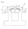
- the wiring pattern (pattern configured of resistive element) 159 is required to be provided circular arcuately as shown in figure 27 . Accordingly, there are problems including that the height dimension H10 of the slide switch 151 becomes large compared to that of the slide switch 111 shown in figure 26 .
- the problem to be solved by the present invention or the object is to provide a slide switch which allows the height thereof to be reduced compared with that of the prior art without increasing the size of the operating member in the sliding direction thereof.
- the present invention provides a slide switch comprising: an operating member which moves circular arcuately in a predetermined movement stroke relative to a main surface of a printed wiring board for outputting a plurality of electrical signals and selects between the electrical signals; a converting mechanism for converting a circular arcuate movement of the operating member into a rectilinear movement relative to the main surface of the printed wiring board; and a moving member rectilinearly moved relative to the main surface of the printed wiring board by the converting mechanism and determining, in cooperation with the printed wiring board, an electrified state corresponding to an electrical signal selected by the operating member.
- the circular acrcuate movement of the operating member is converted by the converting mechanism into the rectilinear movement of the moving member. Therefore, it is enabled to reduce the height compared with that of the prior art without increasing the size of the operating member in the movement direction thereof.
- the present embodiment involves a slide switch 21 available as a zoom switch for operating a zooming lens of a video camera or an ON/OFF switch for power supplying, for example.
- the slide switch 21 comprises: an operating member 1 which moves circular arcuately in a predetermined movement stroke relative to the main surface of a printed wiring board 4 for outputting a plurality of electrical signals and selects a desired electrical signal from the plurality of electrical signals; a converting mechanism 9 for converting the circular arcuate movement of the operating member 1 into a rectilinear movement relative to the main surface of the printed wiring board 4; a moving member 3 rectilinearly moved relative to the main surface of the printed wiring board 4 by the converting mechanism 9 and determining, in cooperation with the printed wiring board 4, an electrified state corresponding to the electrical signal selected by the operating member 1; a base material 23 provided with the printed wiring board 4 and movably supporting each of the operating member 1 and the moving member 3; and a switching brush 6 provided on the moving member 3 and having contacts 27 to contact with wiring patterns 4a of the printed wiring board 4.
- the operating member 1 is configured of an insulating material such as resin and is to be operated by a human finger when the slide switch 21 is installed onto a video camera or the like.
- the operating member 1 engages with a cylindrical lateral face shaped convex surface of the base material 23 so as to form sliding pairs, for example, and is provided as being arcuately movable relative to the base material 23.
- the cylindrical lateral face shaped convex surface of the base material 23 is intended to mean a smaller convex surface when a cylindrical lateral face is divided into two convex surfaces at a plane parallel to the cylindrical axis.
- the moving member 3 is configured of an insulating material such as resin and is constructed as an independent member separated from the operating member 1.
- the moving member 3 engages with the operating member 1 and also engages with a flat surface area of the base material 23 so as to form sliding pairs, for example, at the concave surface side of the cylindrical lateral face shape of the base material 23.
- the moving member 3 is provided as being rectilinearly movable, relative to the base material 23, responding to the movement of the operating member 1 in a direction approximately same as the direction in which the operating member 1 moves.
- the switching brush 6, which is configured of a conductor with elasticity, such as metal, has contacts 27 and is provided with the moving member 3 such that the contacts 27 contact with the wiring patterns 4a.
- the wiring patterns 4a are provided with the printed wiring board 4 of thin plate-like shape and are configured of thin resistive elements or thin conductors.
- the wiring patterns 4a are provided relevantly on the flat surface area of the base material 23 such that the thickness directions of the wiring patterns 4a are orthogonal to the flat surface area of the base material 23 and the longitudinal directions of the wiring patterns 4a are coincident with the movement direction of the moving member 3.
- the base material 23 comprises a flat plate shaped mounting plate 5 configured of a conductor such as metal and a case 2 configured of an insulating material such as resin.
- the slide switch 21 is assembled in the status where the mounting plate 5, the printed wiring board 4, the switching brush 6, the moving member 3, the case 2 and the operating member 1 are overlapped in this order, and the mounting plate 5 is fixed to a housing of video camera or the like thereby the slide switch 21 is embedded on the video camera.
- the direction of overlapping the mounting plate 5, the printed wiring board 4, the switching brush 6, the moving member 3, the case 2 and the operating member 1 i.e. the direction orthogonal to the plane of the mounting plate 5 is referred to as height direction H of the slide switch 21, and the operating member 1 side and the mounting plate 5 side thereof are referred to as upper side and lower side, respectively.
- the moving direction of the moving member 3 or the operating member 1 is referred to as longitudinal direction L of the slide switch 21, and the direction orthogonal to both the height direction H and the longitudinal direction L is referred to as width direction W.
- these directions H, L and W are not necessarily correspond respectively to the height direction, the longitudinal direction and the width direction of the camera.
- the slide switch 21 according to the present embodiment will be hereinafter described in more detail.
- the operating member 1 has, on the engaging side thereof with the base material 23 (lower side in figure 3 ), projecting portions 1a (corresponding to the first engaging portion of the invention) to fit with the moving member 3, engaged portions 1b to be engaged with opening sections 2e of the case 2, click portions 1c formed at ends of the projecting portions 1a for snapping the operating member 1 into the case 2 such that the operating member 1 is capable of rotatively moving (arcuately moving), sliding portions 1d to be guided by side surfaces 2c of the case 2 and each having a projecting amount smaller by L4 (refer to figure 7 ) than that of each projecting portion 1a, and sliding portions 1e to slide on an arcuate sliding surface 2a of the case 2.
- the case 2 intervenes between the sliding portions 1e and the click portions 1c, and the operating member 1 is embedded so as to be capable of rotatively moving (arcuately moving) along the sliding surface 2a of the case 2.
- the case 2 of the base material 23 has the arcuate sliding surface 2a to perform as a guide when the operating member 1 rotatively moves, sliding surfaces 2b provided as being parallel to the mounting plate 5 and moving the moving member 3 parallel to the mounting surface, sliding portions 2c to be engaged with the sliding portions 1d of the operating member 1, stopper portions 2d to be limiters when the moving member 3 moves, and opening sections 2e to be inserted with the engaged portions 1b of the operating member 1 and projecting portions 1a having click portions 1c for snapping in.
- the case 2 is fixed to the mounting plate 5 by welding or the like after lapping the moving member 3 with the printed wiring board 4 such that the moving member 3 becomes to be movable.
- the case 2 is configured of a material with remarkable slidability such as polyacetal because the case 2 has sliding portions with the operating member 1 and the moving member 3.
- the projecting portion 1a shown in the right side of figure 7 elastically deforms toward the left side to generate a reaction force which allows the edge of the relevant opening section 2e to deform elastically towards the right side, and concurrently with this, the projecting portion 1a shown in the left side of figure 7 elastically deforms toward the right side to generate a reaction force which allows the edge of the relevant opening section 2e to deform elastically towards the left side.
- the projecting portions 1a of the operating member 1 penetrate the opening sections 2e of the case 2, and the click portions 1c formed with top ends of the projecting portions 1a of the operating member 1 prevent the operating member 1 from separating from the case 2 thereby allowing the operating member 1 to be supported.
- the moving member 3 has at least one fitting portion 3a (corresponding to the second engaging portion of the invention) formed with curved surfaces 3b to be nipped between one pair of projecting portions 1a of the operating member 1 and projecting toward the side (upper side in figure 3 ) where the operating member 1 is provided, and limiting portions 3c to limit the movement of the moving member 3 when getting in touch with the stopper portions 2d of the case 2.
- two fitting portions 3a are provided each corresponding to the one pair of projecting portions 1a of the operating member 1.
- the moving member 3 has a concave area formed to be attached with the switching brush 6, and the switching brush 6 is attached in such a manner that the contact 27 is projected by a certain amount, thereby providing a structure where the switching brush 6 is restricted to flexurally bend within a certain range even though the moving member 3 is pressed onto the printed wiring board 4.
- the slide switch 21 involves the converting mechanism 9 which converts the circular arcuate movement of the operating member 1 into the rectilinear movement of the moving member 3, and the converting mechanism 9 comprises the projecting portions 1a of the operating member 1 and the fitting portions 3a of the moving member 3.
- projecting portions similar to the projecting portions 1a may be formed on the moving member 3 side
- fitting portions similar to the fitting portions 3a may be formed on the operating member 1 side.
- the operating member 1 has two pairs of projecting portions 1a arranged in the width direction at the side (lower side in figure 3 ) to be engaged with the case 2 and to be provided with the moving member 3, and the moving member 3 has two fitting portions 3a each of which projects toward the side (upper side in figure 3 ) to be provided with the operating member 1 and is to be nipped between each pair of the projecting portions 1a of the operating member 1.
- Each fitting portion 3a has a top end formed with curved surfaces 3b each forming a part of cylindrical shape, and each curved surface 3b of the top end forms a sliding pair with each projecting portion 1a of the operating member 1 thereby allowing the moving member 3 to move with scarce space responding to the movement of the operating member 1.
- the top end of the cylindrical fitting portion 3a has a cut off portion 41 at an area to be located on the operating member 1 side (upper side in figure 3 ) and not to be touched with the projecting portions 1a of the operating member 1 in order that the fitting portion 3a becomes to be with less projection amount.
- the slide switch 21 has an original position reset mechanism 90 for resetting the operating member 1 to a predetermined original position at the time of departing therefrom.
- the original position reset mechanism 90 is configured essentially of a compression coil spring 8 as an elastic body, and rubber-made cushions 7 structured of materials having shock-absorbing characteristics.
- the compression coil spring 8 is to spring-bias the moving member 3 in order that the moving member 3 and the operating member 1 are positioned at the center regions of strokes thereof, that is, at neutral positions shown in figure 3 and figure5 .
- the rubber-made cushions 7 are provided at both end portions of the compression coil spring 8 in the extensible direction thereof.
- the compression coil spring 8 is provided between a pair of stopper portions 43 of the case 2 such that the extensible direction of the compression coil spring 8 corresponds to the movement direction of the moving member 3.
- each cushion 7 is, as shown in figure 5 , pressed to each stopper portion 43 thereby elastically deforming the compression coil spring 8, and the compression coil spring 8 becomes to have a first length L5 shorter than the free length thereof.
- both ends of the coil spring 8 are attached with the rubber-made cushions 7, and the rubber-made cushions 7 and the coil spring 8 are embedded into the case 2 approximately in the vicinity of the center thereof with the moving member 3 in the status where the coil spring 8 is compressed.
- the neutral position shown in figure 5 one ends of the rubber-made cushions 7 are inserted into the coil spring 8, and other ends 7a are pressed to the case 2 and the moving member 3. Therefore, when the operating member 1 moves from the neutral position as shown in figure 6 , the end surface 7a of one rubber-made cushion 7 is pressed to the moving member 3 and the end surface 7a of the other rubber-made cushion 7 is pressed to the case 2.
- the moving member 3 is forced to return to the neutral position in such a manner.
- the compression coil spring 8 becomes to be with the first length L5, and one cushion 7 out of the cushions 7 is pressed to collision portions 45 of one side provided on the moving member 3, while the other cushion 7 out of the cushions 7 is pressed to collision portions 45 of the other side provided on the moving member 3.
- the compression coil spring 8 is elastically deformed to be with a second length L6 (refer to figure 6 ) shorter than the first length L5 because the compression coil spring 8 is compressed between collision portions 45 of one side out of the collision portions 45 and one stopper portion 43 out of the stopper portions 43.
- the collision portions 45 of the moving member 3 intervene between the stopper portions 43 of the case 2. Therefore, when the moving member 3 and the operating member 1 are at center regions of strokes thereof, the cushion 7 located at one end of the compression coil spring 8 is to be pressed with one stopper portion 43 and two stopper portions 43, while the cushion 7 located at the other end of the compression coil spring 8 is also to be pressed with the other stopper portion 43 and the other two collision portions 45.
- the switching brush 6 is attached to the moving member 3, and is to be slid on the wiring patterns 4a thereby causing an electrical signal to be generated.
- the switching brush 6 is obtained through preparing a thin plate-like member formed with contacts 27 at one end area and having an elasticity, and folding the thin plate-like member along a region 29 such that the contacts 27 are located outward, thereby to be formed as being narrow width U-shaped.
- the switching brush 6 has an elasticity in a direction connecting between the one end area of the switching brush 6 and the other end area facing thereto, that is, the height direction (vertical direction in figure 3 ) of the slide switch 21.
- the other end area side of the switching brush 6 is integrally provided on the moving member 3 such that a direction connecting the contacts 27 and the other end area to the folded region 29 corresponds to the movement direction of the moving member 3 i.e. such that the folded switching brush 6 is to become extended in the horizontal direction in figure 3 .
- the switching brush 6 By providing the switching brush 6 in such a manner, the contacts 27 are exposed outward at the lower side of the moving member 3 thereby being to contact with the wiring patterns 4a.
- the contacts 27 of the switching brush 6 are deviated away from the center of the moving member 3 by a certain distance L1 in the movement direction of the moving member 3 (the horizontal direction in figure 3 ; the longitudinal direction of the slide switch).
- the folded region 29 of the switching brush 6 is positioned at the opposite side to the contacts 27 across the center of the moving member 3.
- the center position of the moving member 3 in the movement direction (horizontal direction in figure 3 ) of the moving member 3 and the center position of the switching brush 6 in the direction connecting between the contacts 27 and the folded region 29 are coincident with each other.
- the dimension L2 and the dimension L3 shown in figure 3 are substantially equal to each other.
- the printed wiring board 4 has: a thin plate-like printed wiring board main body 31 configured of an insulating member such as resin; a conductor thin film 33 configured of a conductive member of metal or the like such as silver and thinly provided on substantially whole of one surface of the printed wiring board main body 31 in the thickness direction thereof; wiring patterns 4a provided on the other surface of the printed wiring board main body 31 in the thickness direction thereof and on one end side of the longitudinal direction of the printed wiring board main body 31; and a through opening 35 provided on the other end side of the longitudinal direction of the printed wiring board main body 31.
- the wiring patterns 4a are provided on the thin plate-like printed wiring board 4 described hereinbefore by means of patterning.
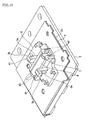
- the printed wiring board 4 is, as shown in figure 16 and figure 17 , formed to be folded at the center region (straight line CL1) in the longitudinal direction of the printed wiring board main body 31 thereby being duplicated such that the conductor thin film 33 is located outward (refer to figure 18 ). In such a status where the printed wiring board 4 is duplicated in itself, only the wiring patterns 4a and the region in the vicinity thereof are exposed to be approachable via the through opening 35.
- the printed wiring board 4 is provided integrally with the mounting plate 5 such that a region 37 of one end side in the longitudinal direction on which the through opening 35 is not provided is contacted with the mounting plate 5 i.e. such that the wiring patterns 4a are exposed upward in figure 3 , and the moving member 3 contacts with and slides on a region (region on which the conductor thin film 33 is provided; region of the conductor thin film 33 shown in figure 4 as being flat plane, for example) of the printed wiring board 4 other than the region on which the through opening 35 is provided.
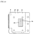
- Figure 10 illustrates an example of wiring patterns for a zooming volume switch of a video camera, wherein wiring patterns 4a configured of carbon resistive elements are arranged in rectangular shapes on the printed wiring board 4.
- One wiring pattern 4a is a common pattern and the other wiring pattern 4a constitutes a resister.
- FIG 14 by coincidentally contacting the switching brush 6 with two wiring patterns 4a and moving the switching brush 6, the resistance through the wiring patterns 4a changes thereby to generate an analog electrical signal.
- figure 11 illustrates an example of wiring patterns for an ON/OFF switch, wherein wiring patterns 104a and 104b configured of carbon resistive elements are provided on a printed wiring board 104.
- the wiring patterns 104a are patterns for signals and the wiring pattern 104b is a common pattern.
- there are generated digital signals such as an ON signal when the switching brush 6 is coincidentally positioned on the wiring pattern 104a and the wiring pattern 104b and an OFF signal when the switching brush 6 is not coincidentally positioned on the wiring pattern 104a and the wiring pattern 104b.
- the moving member 3 stops to move when the limiting portion 3c of the moving member 3 makes contact with the stopper portion 2d of the case 2, and thus the strokes of the operating member 1 and the moving member 3 are determined.
- the switching brush 6 provided integrally with the moving member 3 moves in the same manner with the moving member 3, the switching brush 6 slides on the wiring patterns 4a of the printed wiring board 4 thereby causing a signal to be generated in accordance with the position thereof.
- the compression coil spring 8 forces the moving member 3 and the operating member 1 to return to the neutral positions thereof and the switching brush 6 also returns to the neutral position responding to the moving member 3, and thus after sliding on the wiring patterns 4a of the printed wiring board 4, the switching brush 6 causes a signal to be generated depending on the neutral position.
- the slide switch 21 according to the present embodiment may be assembled in the following manner.
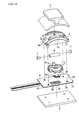
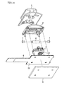
- the printed wiring board 4 in the status shown in figure 16 and figure 17 is folded at the region of the straight line CL1 to be as shown in figure 18 and figure 19 .
- the switching brush 6 (brush 6) is integrally fixed to the moving member 3 by welding, for example, in the status as shown in figure 18 and figure 19 .
- the cushions 7 are attached to both ends of the compression coil spring 8, and the compression coil spring 8 and the cushions 7 are provided on the moving member 3.
- the case 2 is integrally fixed to the mounting plate 5 by welding, for example, such that the printed wiring board 4 and the moving member 3 provided with the compression coil spring 8 and the cushions7 intervene between the case 2 and the mounting plate 5.
- the operating member 1 is attached to the case 2, and thus the slide switch 21 is completed to be assembled.
- the slide switch 21 is constructed such that the operating member 1 moves circular arcuately and the moving member 3 provided with the switching brush 6 moves rectilinearly. Therefore, the wiring patterns 4a to be contacted with the switching brush 6 are enabled to be formed rectilinearly.
- the height of the slide switch is enabled to be more reduced than that of the prior art slide switch (for example, the prior art slide switch 151 shown in figure 27 ) without reducing the movement stroke of the operating member 1 i.e. in spite of approximately equalizing the movement stroke with that of the prior art slide switch 111, for example, and without increasing the dimension (longitudinal size) of the operating member 1 in the movement (sliding) direction i.e. in spite of approximately equalizing the dimension with that of the prior art slide switch 151, for example.
- the slide switch 21 according to the present embodiment has a structure where the operating member 1 and the moving member 3 are provided separately. Therefore, even though the operating member 1 is applied with a force to twist the operating member 1 (for example, rotational moment to change the attitude of the operating member 1), the twisting force is hard to be transmitted to the moving member 3 and the switching brush 6. Accordingly, the attitudes of the moving member 3 and the switching brush 6 are difficult to change, and the displacements of the contacts27 (pattern misalignments) of the switching brush 6 relative to the wiring patterns 4a provided on the printed wiring board 4 are prevented from occurring.
- a force to twist the operating member 1 for example, rotational moment to change the attitude of the operating member 1
- the twisting force is hard to be transmitted to the moving member 3 and the switching brush 6. Accordingly, the attitudes of the moving member 3 and the switching brush 6 are difficult to change, and the displacements of the contacts27 (pattern misalignments) of the switching brush 6 relative to the wiring patterns 4a provided on the printed wiring board 4 are prevented from occurring.
- deviating positions of the contacts 27 allows the longitudinal dimension of the slide switch 21 (sizes of the operating member 1 and the moving member 3 in the movement directions) to be shortened.
- the folded region 29 of the switching brush 6 is to move by the same distance to the right.
- the length of the slide switch 21 is required to be longer responding to the distance of movement toward the right.
- modification may disable the switching brush 6 to obtain a sufficient elasticity (elasticity in the vertical direction in figure 3 ; elasticity required for pressing the wiring patterns 4a with the contacts 27), thereby causing a contact failure and the like to occur between the contacts 27 and the wiring patterns 4a.
- the contacts 27 are deviated away from the center of the moving member 3 by the certain distance L1 in the movement direction of the moving member 3, and the folded region 29 is positioned at the opposite side to the contacts 27 across the center of the moving member 3. Therefore, the switching brush 6 is enabled to obtain a sufficient elasticity thereby to prevent a contact failure and the like from occurring between the contacts 27 and the wiring patterns 4a and to avoid an increase in the longitudinal dimension of the slide switch 21.
- the slide switch 21 of the present embodiment at the time of embedding the operating member 1 to the base material 23, only the projecting portions 1a of the operating member 1 get into touch with the opening sections 2e of the case 2, and both the projecting portions 1a of the operating member 1 and the opening sections 2e of the case 2 deform elastically. Therefore, it becomes unnecessary to increase the projecting amounts (heights) of the projecting portions 1a of the operating member 1 in order for the projecting portions 1a of the operating member 1 to be easily deformed. Accordingly, even though the projecting amounts of the projecting portions 1a of the operating member 1 are small, the operating member 1 is to be easily embedded to the case 2, and thus it is enabled to suppress the increase of the height of the slide switch 21.
- the conductor thin film 33 of the printed wiring board 4 is contacted with the mounting plate 5 configured of a conductive material. Therefore, it is enabled to discharge the unwanted charges charged in the printed wiring board 4 to the mounting plate 5 thereby preventing damages of the printed wiring board 4 and the like.
- the moving member 3 is to contact with and slide on the region 37 (the conductor thin film 33) other than the region of the printed wiring board 4 where the through opening 35 is provided. Therefore, the wiring patterns 4a and the printed wiring board main body 31 are avoided from scraping thereby having abilities of long term uses.
- the cylindrical top end of the fitting portion 3a has the cut off portion 41 at the area located on the operating member 1 side in order that the fitting portion 3a becomes to be with less projection amount. Therefore, it is enabled to shorten the distance between the moving member 3 and the operating member 1 thereby further lowering the height of the slide switch 21.
- cushions 7 are provided at both ends of the compression coil spring 8. Therefore, at the time that the moving member 3 returns to the neutral position after having moved from the neutral position, either one of the cushions 7 other than the compression coil spring 8 is to come into collision with the stopper portion 43 of the case 2, thereby absorbing the impact power and suppressing generation of noises.
Landscapes
- Slide Switches (AREA)
- Adjustable Resistors (AREA)
- Push-Button Switches (AREA)
Abstract
Disclosed is a slide switch comprising: an operating member which moves circular arcuately in a predetermined movement stroke relative to a main surface of a printed wiring board for outputting a plurality of electrical signals and selects between the electric signals; a converting mechanism for converting a circular arcuate movement of the operating member into a rectilinear movement relative to the main surface of the printed wiring board; and a moving member rectilinearly moved relative to the main surface of the printed wiring board by the converting mechanism and determining, in cooperation with the printed wiring board, an electrified state corresponding to an electric signal selected by the operating member.
Description
- The present invention is directed to a slide switch, and more particularly relates to a slide switch in which an electrified state such as resistance value varies in accordance that an operating member is manually operated.
- It is to be noted that, for those designated countries which permit the incorporation by reference, the contents described and/or illustrated in the documents relevant to Japanese Patent Application No.
2008-11675 filed on January 22, 2008 - As shown in
figure 26 , known in the art is aslide switch 111 configured such that anoperating member 113 is rectilinearly operated along the horizontal direction infigure 26 , while a movingmember 115 cooperating with theoperating member 113 and abrush constructing member 117 integrally provided with the movingmember 115 also rectilinearly move, thereby varying a resistance value and the like (Patent Document 1). - Because electronic devices such as video cameras in which the
slide switch 111 is to be used are progressed to being reduced more and more in sizes, it is required to minimize the dimensions of theslide switch 111 as much as possible. To this end, it may be conceivable to reduce the longitudinal dimension of theslide switch 111 i.e. the size along the horizontal direction infigure 26 . However, if the longitudinal dimension is reduced, then the stroke of theoperating member 113 is also to be reduced thereby deteriorating the handling feelings. - In such circumstances, as shown in
figure 27 andfigure 28 , there is proposed aslide switch 151 configured such that anoperating member 153 is moved circular arcuately relative to abase material 115 along the arrow shown infigure 27 thereby preventing the reduction in stroke of the operating member 153 (Patent Document 2). In thisslide switch 151, abrush constructing member 157 provided with theoperating member 153 is also moved circular arcuately.
[Patent Document 1] Japanese Patent Application publication No.H8(1996)-115637
[Patent Document 2] Japanese Patent Application Publication No.2006-236784 - According to the
slide switch 151 disclosed in theabove Patent Document 2, however, the wiring pattern (pattern configured of resistive element) 159 is required to be provided circular arcuately as shown infigure 27 . Accordingly, there are problems including that the height dimension H10 of theslide switch 151 becomes large compared to that of theslide switch 111 shown infigure 26 . - The problem to be solved by the present invention or the object is to provide a slide switch which allows the height thereof to be reduced compared with that of the prior art without increasing the size of the operating member in the sliding direction thereof.
- In order to solve the above problem, the present invention provides a slide switch comprising: an operating member which moves circular arcuately in a predetermined movement stroke relative to a main surface of a printed wiring board for outputting a plurality of electrical signals and selects between the electrical signals; a converting mechanism for converting a circular arcuate movement of the operating member into a rectilinear movement relative to the main surface of the printed wiring board; and a moving member rectilinearly moved relative to the main surface of the printed wiring board by the converting mechanism and determining, in cooperation with the printed wiring board, an electrified state corresponding to an electrical signal selected by the operating member.
- According to the present invention, the circular acrcuate movement of the operating member is converted by the converting mechanism into the rectilinear movement of the moving member. Therefore, it is enabled to reduce the height compared with that of the prior art without increasing the size of the operating member in the movement direction thereof.
-
- [
FIG. 1] Figure 1 is a perspective view illustrating a slide switch according to an embodiment of the present invention. - [
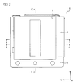
FIG. 2] Figure 2 is a plan view illustrating the slide switch shown infigure 1 . - [
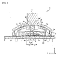
FIG. 3] Figure 3 is a cross-sectional view along the line A-A infigure 2 (operating member 1 being at neutral position). - [
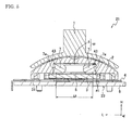
FIG. 4] Figure 4 is a cross-sectional view along the line A-A infigure 2 (operating member 1 being at one side). - [
FIG. 5] Figure 5 is a cross-sectional view along the line B-B infigure 2 (operating member 1 being at neutral position). - [
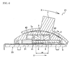
FIG. 6] Figure 6 is a cross-sectional view along the line B-B infigure 2 (operating member 1 being at one side). - [
FIG. 7] Figure 7 is a cross-sectional view along the line C-C infigure 2 . - [
FIG. 8] Figure 8 is an enlarged view of a fitting portion of the moving member shown infigure 3 . - [
FIG. 9] Figure 9 is an enlarged view of a fitting portion of the moving member shown infigure 4 . - [
FIG. 10] Figure 10 is a plan view illustrating an example of wiring patterns of a printed wiring board. - [
FIG. 11] Figure 11 is a plan view illustrating another example of wiring patterns of a printed wiring board. - [
FIG. 12] Figure 12 is a perspective view illustrating a status where the operating member is subtracted from the slide switch shown infigure 1 . - [
FIG. 13] Figure 13 is a perspective view illustrating a status where the case is subtracted from the status shown infigure 12 . - [
FIG. 14] Figure 14 is a perspective view illustrating a status where the moving member, rubbers and coil spring are subtracted from the status shown infigure 13 . - [
FIG. 15] Figure 15 is a perspective view illustrating a status where the printed wiring board is embedded into the slide switch shown infigure 1 . - [
FIG. 16] Figure 16 is a perspective view illustrating a status where the slide switch is exploded infigure 15 (the printed wiring board not being folded). - [
FIG. 17] Figure 17 is a perspective view illustrating a status where the slide switch is exploded infigure 15 (the printed wiring board not being folded). - [
FIG. 18] Figure 18 is a perspective view illustrating a status where the slide switch is exploded infigure 15 (the printed wiring board being folded). - [
FIG. 19] Figure 19 is a perspective view illustrating a status where the slide switch is exploded infigure 15 (the printed wiring board being folded). - [
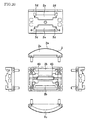
FIG. 20] Figure 20 provides trigonometric six basic views illustrating the case shown infigure 1 . - [
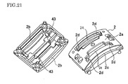
FIG. 21] Figure 21 provides perspective views (top and back) illustrating the case shown infigure 1 . - [
FIG. 22] Figure 22 provides trigonometric six basic views illustrating the operating member shown infigure 1 . - [
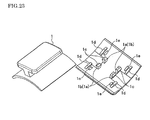
FIG. 23] Figure 23 provides perspective views illustrating the operating member shown infigure 1 . - [
FIG. 24] Figure 24 provides trigonometric six basic views illustrating the moving member shown infigure 1 . - [
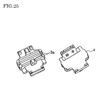
FIG. 25] Figure 25 provides perspective views illustrating the moving member shown infigure 1 . - [
FIG. 26] Figure 26 is a cross-sectional view illustrating a prior art slide switch. - [
FIG. 27] Figure 27 is a schematic view illustrating another prior art slide switch. - [
FIG. 28] Figure 28 is a perspective view illustrating the slide switch shown infigure 27 . -
- 1; operating member
- 1a; projecting portions (first engaging portion)
- 1b; engaged portions
- 1c; click portions
- 1d; sliding portions
- 1e; sliding portions
- 2; case
- 2a; sliding surface
- 2b; sliding surfaces
- 2c; sliding portions
- 2d; stopper portions
- 2e; opening sections
- 3; moving member
- 3a; fitting portions (second engaging portion)
- 3b; curved surfaces
- 3c; limiting portions
- 4; printed wiring board
- 4a; wiring patterns
- 5; mounting plate
- 6; switching brush
- 7; cushions
- 8; compression coil spring
- 9; converting mechanism
- 21; slide switch
- 23; base material
- 27; contacts
- 29; folded region
- 31; printed wiring board main body
- 33; conductor thin film
- 35; through opening
- 41; cut off portions
- 90; original position reset mechanism
- Hereinafter, embodiments according to the present invention will be described referring to the drawings. The present embodiment involves a
slide switch 21 available as a zoom switch for operating a zooming lens of a video camera or an ON/OFF switch for power supplying, for example. - As shown in
figure 1 to figure 3 , theslide switch 21 according to the present embodiment comprises: an operatingmember 1 which moves circular arcuately in a predetermined movement stroke relative to the main surface of a printedwiring board 4 for outputting a plurality of electrical signals and selects a desired electrical signal from the plurality of electrical signals; a convertingmechanism 9 for converting the circular arcuate movement of the operatingmember 1 into a rectilinear movement relative to the main surface of the printedwiring board 4; a movingmember 3 rectilinearly moved relative to the main surface of the printedwiring board 4 by the convertingmechanism 9 and determining, in cooperation with the printedwiring board 4, an electrified state corresponding to the electrical signal selected by the operatingmember 1; abase material 23 provided with the printedwiring board 4 and movably supporting each of the operatingmember 1 and the movingmember 3; and a switchingbrush 6 provided on the movingmember 3 and havingcontacts 27 to contact withwiring patterns 4a of the printedwiring board 4. - The operating
member 1 is configured of an insulating material such as resin and is to be operated by a human finger when theslide switch 21 is installed onto a video camera or the like. In addition, the operatingmember 1 engages with a cylindrical lateral face shaped convex surface of thebase material 23 so as to form sliding pairs, for example, and is provided as being arcuately movable relative to thebase material 23. It is to be noted that the cylindrical lateral face shaped convex surface of thebase material 23 is intended to mean a smaller convex surface when a cylindrical lateral face is divided into two convex surfaces at a plane parallel to the cylindrical axis. - The moving
member 3 is configured of an insulating material such as resin and is constructed as an independent member separated from the operatingmember 1. In addition, the movingmember 3 engages with the operatingmember 1 and also engages with a flat surface area of thebase material 23 so as to form sliding pairs, for example, at the concave surface side of the cylindrical lateral face shape of thebase material 23. More specifically, the movingmember 3 is provided as being rectilinearly movable, relative to thebase material 23, responding to the movement of the operatingmember 1 in a direction approximately same as the direction in which the operatingmember 1 moves. - The switching
brush 6, which is configured of a conductor with elasticity, such as metal, hascontacts 27 and is provided with the movingmember 3 such that thecontacts 27 contact with thewiring patterns 4a. - The
wiring patterns 4a are provided with the printedwiring board 4 of thin plate-like shape and are configured of thin resistive elements or thin conductors. Thewiring patterns 4a are provided relevantly on the flat surface area of thebase material 23 such that the thickness directions of thewiring patterns 4a are orthogonal to the flat surface area of thebase material 23 and the longitudinal directions of thewiring patterns 4a are coincident with the movement direction of the movingmember 3. - The
base material 23 comprises a flat plate shaped mountingplate 5 configured of a conductor such as metal and acase 2 configured of an insulating material such as resin. - The
slide switch 21 is assembled in the status where the mountingplate 5, the printedwiring board 4, the switchingbrush 6, the movingmember 3, thecase 2 and the operatingmember 1 are overlapped in this order, and the mountingplate 5 is fixed to a housing of video camera or the like thereby theslide switch 21 is embedded on the video camera. - In the present specification, the direction of overlapping the mounting
plate 5, the printedwiring board 4, the switchingbrush 6, the movingmember 3, thecase 2 and the operatingmember 1 i.e. the direction orthogonal to the plane of the mountingplate 5 is referred to as height direction H of theslide switch 21, and the operatingmember 1 side and the mountingplate 5 side thereof are referred to as upper side and lower side, respectively. In addition, the moving direction of the movingmember 3 or the operatingmember 1 is referred to as longitudinal direction L of theslide switch 21, and the direction orthogonal to both the height direction H and the longitudinal direction L is referred to as width direction W. These directions H, L and W are indicated in primary drawings as "H", "L" and "W", respectively. - It is to be noted that, when the
slide switch 21 according to the present embodiment is embedded into a video camera or the like, these directions H, L and W are not necessarily correspond respectively to the height direction, the longitudinal direction and the width direction of the camera. - The
slide switch 21 according to the present embodiment will be hereinafter described in more detail. - As shown in the right of
figure 23 , the operatingmember 1 has, on the engaging side thereof with the base material 23 (lower side infigure 3 ), projectingportions 1a (corresponding to the first engaging portion of the invention) to fit with the movingmember 3, engagedportions 1b to be engaged withopening sections 2e of thecase 2, clickportions 1c formed at ends of the projectingportions 1a for snapping the operatingmember 1 into thecase 2 such that the operatingmember 1 is capable of rotatively moving (arcuately moving), slidingportions 1d to be guided byside surfaces 2c of thecase 2 and each having a projecting amount smaller by L4 (refer tofigure 7 ) than that of each projectingportion 1a, and slidingportions 1e to slide on an arcuate slidingsurface 2a of thecase 2. When the operatingmember 1 is snapped into thecase 2, thecase 2 intervenes between the slidingportions 1e and theclick portions 1c, and the operatingmember 1 is embedded so as to be capable of rotatively moving (arcuately moving) along the slidingsurface 2a of thecase 2. - On the other hand, as shown in
figure 20 andfigure 21 , thecase 2 of thebase material 23 has the arcuate slidingsurface 2a to perform as a guide when the operatingmember 1 rotatively moves, slidingsurfaces 2b provided as being parallel to the mountingplate 5 and moving the movingmember 3 parallel to the mounting surface, slidingportions 2c to be engaged with the slidingportions 1d of the operatingmember 1,stopper portions 2d to be limiters when the movingmember 3 moves, and openingsections 2e to be inserted with the engagedportions 1b of the operatingmember 1 and projectingportions 1a havingclick portions 1c for snapping in. Thecase 2 is fixed to the mountingplate 5 by welding or the like after lapping the movingmember 3 with the printedwiring board 4 such that the movingmember 3 becomes to be movable. In addition, thecase 2 is configured of a material with remarkable slidability such as polyacetal because thecase 2 has sliding portions with the operatingmember 1 and the movingmember 3. - When embedding the operating
member 1 onto thecase 2 of thebase material 23, by moving the operatingmember 1 positioned above thebase material 23 toward thebase material 23, only the projectingportions 1a of the operatingmember 1 get into touch with the openingsections 2e of thecase 2, and the projectingportions 1a of the operatingmember 1 and the openingsections 2e of thecase 2 deform elastically. More specifically, the projectingportion 1a shown in the right side offigure 7 elastically deforms toward the left side to generate a reaction force which allows the edge of therelevant opening section 2e to deform elastically towards the right side, and concurrently with this, the projectingportion 1a shown in the left side offigure 7 elastically deforms toward the right side to generate a reaction force which allows the edge of therelevant opening section 2e to deform elastically towards the left side. - Thereafter, by further moving the operating
member 1 toward thebase material 23, these above elastic deformations are released, and the slidingportions 1d of the operatingmember 1 and the slidingportions 2c of thecase 2 are engaged with each other thereby completing the embedment of the operatingmember 1 to thecase 2. - In the status of completing the embedment in such a manner, the projecting
portions 1a of the operatingmember 1 penetrate the openingsections 2e of thecase 2, and theclick portions 1c formed with top ends of the projectingportions 1a of the operatingmember 1 prevent the operatingmember 1 from separating from thecase 2 thereby allowing the operatingmember 1 to be supported. - As shown in
figure 24 andfigure 25 , the movingmember 3 has at least onefitting portion 3a (corresponding to the second engaging portion of the invention) formed withcurved surfaces 3b to be nipped between one pair of projectingportions 1a of the operatingmember 1 and projecting toward the side (upper side infigure 3 ) where the operatingmember 1 is provided, and limitingportions 3c to limit the movement of the movingmember 3 when getting in touch with thestopper portions 2d of thecase 2. In the shown example, twofitting portions 3a are provided each corresponding to the one pair of projectingportions 1a of the operatingmember 1. In addition, the movingmember 3 has a concave area formed to be attached with the switchingbrush 6, and the switchingbrush 6 is attached in such a manner that thecontact 27 is projected by a certain amount, thereby providing a structure where the switchingbrush 6 is restricted to flexurally bend within a certain range even though the movingmember 3 is pressed onto the printedwiring board 4. - The
slide switch 21 according to the present embodiment involves the convertingmechanism 9 which converts the circular arcuate movement of the operatingmember 1 into the rectilinear movement of the movingmember 3, and the convertingmechanism 9 comprises the projectingportions 1a of the operatingmember 1 and thefitting portions 3a of the movingmember 3. Alternatively, projecting portions similar to the projectingportions 1a may be formed on the movingmember 3 side, and fitting portions similar to thefitting portions 3a may be formed on the operatingmember 1 side. - As described hereinbefore, the operating
member 1 has two pairs of projectingportions 1a arranged in the width direction at the side (lower side infigure 3 ) to be engaged with thecase 2 and to be provided with the movingmember 3, and the movingmember 3 has twofitting portions 3a each of which projects toward the side (upper side infigure 3 ) to be provided with the operatingmember 1 and is to be nipped between each pair of the projectingportions 1a of the operatingmember 1. - Each
fitting portion 3a has a top end formed withcurved surfaces 3b each forming a part of cylindrical shape, and eachcurved surface 3b of the top end forms a sliding pair with each projectingportion 1a of the operatingmember 1 thereby allowing the movingmember 3 to move with scarce space responding to the movement of the operatingmember 1. In addition, the top end of the cylindricalfitting portion 3a has a cut offportion 41 at an area to be located on the operatingmember 1 side (upper side infigure 3 ) and not to be touched with the projectingportions 1a of the operatingmember 1 in order that thefitting portion 3a becomes to be with less projection amount. - Moreover, the
slide switch 21 according to the present embodiment has an original position resetmechanism 90 for resetting the operatingmember 1 to a predetermined original position at the time of departing therefrom. The original position resetmechanism 90 is configured essentially of acompression coil spring 8 as an elastic body, and rubber-madecushions 7 structured of materials having shock-absorbing characteristics. - The
compression coil spring 8 is to spring-bias the movingmember 3 in order that the movingmember 3 and the operatingmember 1 are positioned at the center regions of strokes thereof, that is, at neutral positions shown infigure 3 andfigure5 . In addition, the rubber-madecushions 7 are provided at both end portions of thecompression coil spring 8 in the extensible direction thereof. - The
compression coil spring 8 is provided between a pair ofstopper portions 43 of thecase 2 such that the extensible direction of thecompression coil spring 8 corresponds to the movement direction of the movingmember 3. In the status where thecompression coil spring 8 is provided in such a manner, eachcushion 7 is, as shown infigure 5 , pressed to eachstopper portion 43 thereby elastically deforming thecompression coil spring 8, and thecompression coil spring 8 becomes to have a first length L5 shorter than the free length thereof. - As shown in
figure 5 , both ends of thecoil spring 8 are attached with the rubber-madecushions 7, and the rubber-madecushions 7 and thecoil spring 8 are embedded into thecase 2 approximately in the vicinity of the center thereof with the movingmember 3 in the status where thecoil spring 8 is compressed. Referring to the neutral position shown infigure 5 , one ends of the rubber-madecushions 7 are inserted into thecoil spring 8, andother ends 7a are pressed to thecase 2 and the movingmember 3. Therefore, when the operatingmember 1 moves from the neutral position as shown infigure 6 , theend surface 7a of one rubber-madecushion 7 is pressed to the movingmember 3 and theend surface 7a of the other rubber-madecushion 7 is pressed to thecase 2. Thus, there is obtained a structure where the movingmember 3 is forced to return to the neutral position in such a manner. - More specifically, when the moving
member 3 and the operatingmember 1 are positioned at center regions of strokes thereof as shown infigure 3 orfigure 5 , thecompression coil spring 8 becomes to be with the first length L5, and onecushion 7 out of thecushions 7 is pressed tocollision portions 45 of one side provided on the movingmember 3, while theother cushion 7 out of thecushions 7 is pressed tocollision portions 45 of the other side provided on the movingmember 3. - In contrast, when the moving
member 3 is moved from the neutral position as shown infigure 4 orfigure 6 , thecompression coil spring 8 is elastically deformed to be with a second length L6 (refer tofigure 6 ) shorter than the first length L5 because thecompression coil spring 8 is compressed betweencollision portions 45 of one side out of thecollision portions 45 and onestopper portion 43 out of thestopper portions 43. - It is to be noted that, in the width direction of the
slide switch 21, as shown infigure 13 , thecollision portions 45 of the movingmember 3 intervene between thestopper portions 43 of thecase 2. Therefore, when the movingmember 3 and the operatingmember 1 are at center regions of strokes thereof, thecushion 7 located at one end of thecompression coil spring 8 is to be pressed with onestopper portion 43 and twostopper portions 43, while thecushion 7 located at the other end of thecompression coil spring 8 is also to be pressed with theother stopper portion 43 and the other twocollision portions 45. In contrast, when the movingmember 3 and the operatingmember 1 are moved from the neutral positions, thecushion 7 located at one end of thecompression coil spring 8 is pressed only with onestopper portion 43, while thecushion 7 located at the other end of thecompression coil spring 8 is pressed only with twocollision portions 45. - The switching
brush 6 is attached to the movingmember 3, and is to be slid on thewiring patterns 4a thereby causing an electrical signal to be generated. - As shown in
figure 14 , the switchingbrush 6 according to the present embodiment is obtained through preparing a thin plate-like member formed withcontacts 27 at one end area and having an elasticity, and folding the thin plate-like member along aregion 29 such that thecontacts 27 are located outward, thereby to be formed as being narrow width U-shaped. In addition, the switchingbrush 6 has an elasticity in a direction connecting between the one end area of the switchingbrush 6 and the other end area facing thereto, that is, the height direction (vertical direction infigure 3 ) of theslide switch 21. - More specifically, the other end area side of the switching
brush 6 is integrally provided on the movingmember 3 such that a direction connecting thecontacts 27 and the other end area to the foldedregion 29 corresponds to the movement direction of the movingmember 3 i.e. such that the folded switchingbrush 6 is to become extended in the horizontal direction infigure 3 . By providing the switchingbrush 6 in such a manner, thecontacts 27 are exposed outward at the lower side of the movingmember 3 thereby being to contact with thewiring patterns 4a. - The
contacts 27 of the switchingbrush 6 are deviated away from the center of the movingmember 3 by a certain distance L1 in the movement direction of the moving member 3 (the horizontal direction infigure 3 ; the longitudinal direction of the slide switch). In addition, the foldedregion 29 of the switchingbrush 6 is positioned at the opposite side to thecontacts 27 across the center of the movingmember 3. - Particularly in the present embodiment, the center position of the moving
member 3 in the movement direction (horizontal direction infigure 3 ) of the movingmember 3 and the center position of the switchingbrush 6 in the direction connecting between thecontacts 27 and the foldedregion 29 are coincident with each other. In other words, the dimension L2 and the dimension L3 shown infigure 3 are substantially equal to each other. - The printed
wiring board 4 has: a thin plate-like printed wiring boardmain body 31 configured of an insulating member such as resin; a conductorthin film 33 configured of a conductive member of metal or the like such as silver and thinly provided on substantially whole of one surface of the printed wiring boardmain body 31 in the thickness direction thereof;wiring patterns 4a provided on the other surface of the printed wiring boardmain body 31 in the thickness direction thereof and on one end side of the longitudinal direction of the printed wiring boardmain body 31; and a throughopening 35 provided on the other end side of the longitudinal direction of the printed wiring boardmain body 31. Thewiring patterns 4a are provided on the thin plate-like printedwiring board 4 described hereinbefore by means of patterning. - The printed
wiring board 4 is, as shown infigure 16 andfigure 17 , formed to be folded at the center region (straight line CL1) in the longitudinal direction of the printed wiring boardmain body 31 thereby being duplicated such that the conductorthin film 33 is located outward (refer tofigure 18 ). In such a status where the printedwiring board 4 is duplicated in itself, only thewiring patterns 4a and the region in the vicinity thereof are exposed to be approachable via the throughopening 35. - In addition, the printed
wiring board 4 is provided integrally with the mountingplate 5 such that aregion 37 of one end side in the longitudinal direction on which the throughopening 35 is not provided is contacted with the mountingplate 5 i.e. such that thewiring patterns 4a are exposed upward infigure 3 , and the movingmember 3 contacts with and slides on a region (region on which the conductorthin film 33 is provided; region of the conductorthin film 33 shown infigure 4 as being flat plane, for example) of the printedwiring board 4 other than the region on which the throughopening 35 is provided. -
Figure 10 illustrates an example of wiring patterns for a zooming volume switch of a video camera, whereinwiring patterns 4a configured of carbon resistive elements are arranged in rectangular shapes on the printedwiring board 4. Onewiring pattern 4a is a common pattern and theother wiring pattern 4a constitutes a resister.
As shown infigure 14 , by coincidentally contacting the switchingbrush 6 with twowiring patterns 4a and moving the switchingbrush 6, the resistance through thewiring patterns 4a changes thereby to generate an analog electrical signal. - On the other hand,
figure 11 illustrates an example of wiring patterns for an ON/OFF switch, whereinwiring patterns wiring board 104. Thewiring patterns 104a are patterns for signals and thewiring pattern 104b is a common pattern. In this case, there are generated digital signals such as an ON signal when the switchingbrush 6 is coincidentally positioned on thewiring pattern 104a and thewiring pattern 104b and an OFF signal when the switchingbrush 6 is not coincidentally positioned on thewiring pattern 104a and thewiring pattern 104b. - The operation will be hereinafter described.
- As shown in
figure 4 , when a force in the direction of X arrow is applied to the operatingmember 1 in theslide switch 21 constructed as the above manner, the operatingmember 1 rotatively moves along the slidingsurface 2a of thecase 2 in the direction of X arrow. According to the rotative movement of the operatingmember 1, as shown infigure 8 andfigure 9 , inner wall surfaces of the projectingportions 1a of the operatingmember 1 allows the movingmember 3 to move in the direction of Y arrow against thecompression coil spring 8 while sliding between thecurved surfaces 3b of the movingmember 3. - Thereafter, the moving
member 3 stops to move when the limitingportion 3c of the movingmember 3 makes contact with thestopper portion 2d of thecase 2, and thus the strokes of the operatingmember 1 and the movingmember 3 are determined. - Because the switching
brush 6 provided integrally with the movingmember 3 moves in the same manner with the movingmember 3, the switchingbrush 6 slides on thewiring patterns 4a of the printedwiring board 4 thereby causing a signal to be generated in accordance with the position thereof. - Thereafter, if the force in the direction of X arrow is released, then the
compression coil spring 8 forces the movingmember 3 and the operatingmember 1 to return to the neutral positions thereof and the switchingbrush 6 also returns to the neutral position responding to the movingmember 3, and thus after sliding on thewiring patterns 4a of the printedwiring board 4, the switchingbrush 6 causes a signal to be generated depending on the neutral position. - Incidentally, the
slide switch 21 according to the present embodiment may be assembled in the following manner. - At first, the printed
wiring board 4 in the status shown infigure 16 andfigure 17 is folded at the region of the straight line CL1 to be as shown infigure 18 andfigure 19 . The switching brush 6 (brush 6) is integrally fixed to the movingmember 3 by welding, for example, in the status as shown infigure 18 andfigure 19 . - Next, the
cushions 7 are attached to both ends of thecompression coil spring 8, and thecompression coil spring 8 and thecushions 7 are provided on the movingmember 3. - Then, the
case 2 is integrally fixed to the mountingplate 5 by welding, for example, such that the printedwiring board 4 and the movingmember 3 provided with thecompression coil spring 8 and the cushions7 intervene between thecase 2 and the mountingplate 5. Thereafter, the operatingmember 1 is attached to thecase 2, and thus theslide switch 21 is completed to be assembled. - As described above, the
slide switch 21 according to the present embodiment is constructed such that the operatingmember 1 moves circular arcuately and the movingmember 3 provided with the switchingbrush 6 moves rectilinearly. Therefore, thewiring patterns 4a to be contacted with the switchingbrush 6 are enabled to be formed rectilinearly. In addition, the height of the slide switch is enabled to be more reduced than that of the prior art slide switch (for example, the priorart slide switch 151 shown infigure 27 ) without reducing the movement stroke of the operatingmember 1 i.e. in spite of approximately equalizing the movement stroke with that of the priorart slide switch 111, for example, and without increasing the dimension (longitudinal size) of the operatingmember 1 in the movement (sliding) direction i.e. in spite of approximately equalizing the dimension with that of the priorart slide switch 151, for example. - Moreover, the
slide switch 21 according to the present embodiment has a structure where the operatingmember 1 and the movingmember 3 are provided separately. Therefore, even though the operatingmember 1 is applied with a force to twist the operating member 1 (for example, rotational moment to change the attitude of the operating member 1), the twisting force is hard to be transmitted to the movingmember 3 and the switchingbrush 6. Accordingly, the attitudes of the movingmember 3 and the switchingbrush 6 are difficult to change, and the displacements of the contacts27 (pattern misalignments) of the switchingbrush 6 relative to thewiring patterns 4a provided on the printedwiring board 4 are prevented from occurring. - Furthermore, according to the
slide switch 21, deviating positions of thecontacts 27 allows the longitudinal dimension of the slide switch 21 (sizes of the operatingmember 1 and the movingmember 3 in the movement directions) to be shortened. - More specifically, if the structure shown in
figure 3 is such that thecontacts 27 are shifted to the right direction to be at the same positions as the center positions of the operatingmember 1 and the movingmember 3, the foldedregion 29 of the switchingbrush 6 is to move by the same distance to the right. Thus, the length of theslide switch 21 is required to be longer responding to the distance of movement toward the right. Meanwhile, there may be a conceivable modification that only thecontacts 27 are moved toward the right without moving the foldedregion 29 of the switchingbrush 6 toward the right. However, such modification may disable the switchingbrush 6 to obtain a sufficient elasticity (elasticity in the vertical direction infigure 3 ; elasticity required for pressing thewiring patterns 4a with the contacts 27), thereby causing a contact failure and the like to occur between thecontacts 27 and thewiring patterns 4a. - In the
slide switch 21 according to the present embodiment, thecontacts 27 are deviated away from the center of the movingmember 3 by the certain distance L1 in the movement direction of the movingmember 3, and the foldedregion 29 is positioned at the opposite side to thecontacts 27 across the center of the movingmember 3. Therefore, the switchingbrush 6 is enabled to obtain a sufficient elasticity thereby to prevent a contact failure and the like from occurring between thecontacts 27 and thewiring patterns 4a and to avoid an increase in the longitudinal dimension of theslide switch 21. - In addition, according to the
slide switch 21 of the present embodiment, at the time of embedding the operatingmember 1 to thebase material 23, only the projectingportions 1a of the operatingmember 1 get into touch with the openingsections 2e of thecase 2, and both the projectingportions 1a of the operatingmember 1 and the openingsections 2e of thecase 2 deform elastically. Therefore, it becomes unnecessary to increase the projecting amounts (heights) of the projectingportions 1a of the operatingmember 1 in order for the projectingportions 1a of the operatingmember 1 to be easily deformed. Accordingly, even though the projecting amounts of the projectingportions 1a of the operatingmember 1 are small, the operatingmember 1 is to be easily embedded to thecase 2, and thus it is enabled to suppress the increase of the height of theslide switch 21. - In addition, according to the
slide switch 21 of the present embodiment, the conductorthin film 33 of the printedwiring board 4 is contacted with the mountingplate 5 configured of a conductive material. Therefore, it is enabled to discharge the unwanted charges charged in the printedwiring board 4 to the mountingplate 5 thereby preventing damages of the printedwiring board 4 and the like. - Moreover, the moving
member 3 is to contact with and slide on the region 37 (the conductor thin film 33) other than the region of the printedwiring board 4 where the throughopening 35 is provided. Therefore, thewiring patterns 4a and the printed wiring boardmain body 31 are avoided from scraping thereby having abilities of long term uses. - In addition, according to the
slide switch 21, the cylindrical top end of thefitting portion 3a has the cut offportion 41 at the area located on the operatingmember 1 side in order that thefitting portion 3a becomes to be with less projection amount. Therefore, it is enabled to shorten the distance between the movingmember 3 and the operatingmember 1 thereby further lowering the height of theslide switch 21. - In addition, according to the
slide switch 21, cushions 7 are provided at both ends of thecompression coil spring 8. Therefore, at the time that the movingmember 3 returns to the neutral position after having moved from the neutral position, either one of thecushions 7 other than thecompression coil spring 8 is to come into collision with thestopper portion 43 of thecase 2, thereby absorbing the impact power and suppressing generation of noises.
Claims (15)
- A slide switch comprising:an operating member which moves circular arcuately in a predetermined movement stroke relative to a main surface of a printed wiring board for outputting a plurality of electrical signals and selects between the electrical signals;a converting mechanism for converting a circular arcuate movement of the operating member into a rectilinear movement relative to the main surface of the printed wiring board; anda moving member rectilinearly moved relative to the main surface of the printed wiring board by the converting mechanism and determining, in cooperation with the printed wiring board, an electrified state corresponding to an electrical signal selected by the operating member.
- The slide switch as recited in claim 1, further comprising a base material provided with the printed wiring board and supporting movably each of the operating member and the moving member.
- The slide switch as recited in claim 1 or 2, wherein the converting mechanism comprises:a pair of first engaging portions provided on either one of the operating member and the moving member; anda second engaging portion provided on other one of the operating member and the moving member and having a curved surface to intervene between the pair of first engaging portions.
- The slide switch as recited in claim 3, wherein the first engaging portions and the second engaging portion are configured as being sliding pairs for converting the circular arcuate movement of the operating member into the rectilinear movement of the moving member.
- The slide switch as recited in claim 3 or 4, wherein a top end of the second engaging portion has a cut off portion in order that the second engaging portion becomes to be with less projection amount.
- The slide switch as recited in either one of claims 1 to 5, further comprising an original position reset mechanism for resetting the operating member to a predetermined original position.
- The slide switch as recited in claim 6, wherein the original position reset mechanism includes a compression coil spring provided between either one of the operating member and the moving member and a base material provided with the printed wiring board.
- The slide switch as recited in claim 7, wherein the original reset mechanism further includes cushions provided at both end portions of the compression coil spring, and
each cushion is to pressed to the base material when the operating member moves to at least one of end regions of the movement stroke thereof. - The slide switch as recited in either one of claims 1 to 8, wherein the printed wiring board includes a wiring pattern for generating, with the moving member, an electrical signal which changes in analog form.
- The slide switch as recited in either one of claims 1 to 8, wherein the printed wiring board includes a wiring pattern for generating, with the moving member, an electrical signal which changes in digital form.
- The slide switch as recited in claim 9 or 10, wherein the printed wiring board has:a thin plate-like main body configured of an insulating material and formed with an through opening;a conductive thin film configured of a conductive material and provided on one main surface of the main body; andthe wiring pattern provided on other main surface of the main body, andthe printed wiring board is folded to be duplicated such that the conductive thin film is located outward and the wiring pattern is exposed via the through opening.
- The slide switch as recited in claim 11, wherein the moving member moves while contacting with a region other than the through opening of the printed wiring board folded to be duplicated.
- The slide switch as recited in either one of claims 9 to 12, wherein the moving member is provided with a switching brush having a contact to contact with the wiring pattern.
- The slide switch as recited in claim 13, wherein the switching brush is configured such that a thin plate-like elastic member having a one end portion formed with the contact is folded in such a manner that the contact is located outward, and
the contact and the folded region are located oppositely to each other relative to a center of movement direction of the moving member. - The slide switch as recited in either one of claims 2 to 14, wherein the operating member has a sliding portion with less projecting amount than that of the first engaging portions,
the base material has an opening section to be engaged with the first engaging portion of the operating member and a sliding portion to be engaged with the sliding portion of the operating member, and
when embedding the operating member to the base material, after only the first engaging portions of the operating member are pressed to the opening section of the base material and the first engaging portions and the opening section are elastically deformed, elastic deformations are released and the sliding portion of the operating member and the sliding portion of the base material are engaged with each other.
Applications Claiming Priority (2)
| Application Number | Priority Date | Filing Date | Title |
|---|---|---|---|
| JP2008011675 | 2008-01-22 | ||
| PCT/JP2009/050952 WO2009093644A1 (en) | 2008-01-22 | 2009-01-22 | Slide switch |
Publications (1)
| Publication Number | Publication Date |
|---|---|
| EP2237298A1 true EP2237298A1 (en) | 2010-10-06 |
Family
ID=40901150
Family Applications (1)
| Application Number | Title | Priority Date | Filing Date |
|---|---|---|---|
| EP09704560A Withdrawn EP2237298A1 (en) | 2008-01-22 | 2009-01-22 | Slide switch |
Country Status (5)
| Country | Link |
|---|---|
| US (1) | US8188389B2 (en) |
| EP (1) | EP2237298A1 (en) |
| JP (1) | JPWO2009093644A1 (en) |
| CN (1) | CN101911233A (en) |
| WO (1) | WO2009093644A1 (en) |
Families Citing this family (6)
| Publication number | Priority date | Publication date | Assignee | Title |
|---|---|---|---|---|
| WO2010136446A1 (en) * | 2009-05-25 | 2010-12-02 | Abb Schweiz Ag | Switching unit for a circuit breaker having a toggle lever |
| TWI567528B (en) | 2013-01-10 | 2017-01-21 | 佳能企業股份有限公司 | Sliding mechanism and electronic device using the same |
| CN103929573A (en) * | 2013-01-15 | 2014-07-16 | 佳能企业股份有限公司 | Slide knob mechanism and electronic device applying mechanism |
| JP6410571B2 (en) * | 2014-11-10 | 2018-10-24 | 株式会社ヴァレオジャパン | Switch device |
| JP6434884B2 (en) * | 2015-10-06 | 2018-12-05 | 矢崎総業株式会社 | Display device |
| US12249446B2 (en) * | 2020-04-10 | 2025-03-11 | Fujikura Ltd. | Variable resistor |
Family Cites Families (9)
| Publication number | Priority date | Publication date | Assignee | Title |
|---|---|---|---|---|
| JPS6342415Y2 (en) * | 1981-06-01 | 1988-11-07 | ||
| JPH08115637A (en) | 1994-10-17 | 1996-05-07 | Sony Corp | Automatic return slide switch and slide structure |
| US5685419A (en) * | 1995-09-07 | 1997-11-11 | Daichi Denso Buhin Co., Ltd. | Lever switch |
| JP3670730B2 (en) * | 1995-09-27 | 2005-07-13 | 株式会社トミー | Switch device |
| US6091038A (en) * | 1999-05-27 | 2000-07-18 | Trw Inc. | Electrical switch with sliding terminal contacts |
| US20030094353A1 (en) * | 2001-10-10 | 2003-05-22 | Soren Ravnkilde | Multifunctional switch |
| JP2006140092A (en) * | 2004-11-15 | 2006-06-01 | Teikoku Tsushin Kogyo Co Ltd | Electrostatic component intrusion prevention mechanism |
| CN2772003Y (en) * | 2004-12-30 | 2006-04-12 | 明基电通股份有限公司 | New tactile control mechanism |
| JP2006236784A (en) * | 2005-02-24 | 2006-09-07 | Sony Corp | Rotating electronic components |
-
2009
- 2009-01-22 JP JP2009550549A patent/JPWO2009093644A1/en not_active Ceased
- 2009-01-22 EP EP09704560A patent/EP2237298A1/en not_active Withdrawn
- 2009-01-22 CN CN2009801022838A patent/CN101911233A/en active Pending
- 2009-01-22 WO PCT/JP2009/050952 patent/WO2009093644A1/en not_active Ceased
-
2010
- 2010-07-21 US US12/840,735 patent/US8188389B2/en not_active Expired - Fee Related
Non-Patent Citations (1)
| Title |
|---|
| See references of WO2009093644A1 * |
Also Published As
| Publication number | Publication date |
|---|---|
| WO2009093644A1 (en) | 2009-07-30 |
| CN101911233A (en) | 2010-12-08 |
| JPWO2009093644A1 (en) | 2011-05-26 |
| US8188389B2 (en) | 2012-05-29 |
| US20110017579A1 (en) | 2011-01-27 |
Similar Documents
| Publication | Publication Date | Title |
|---|---|---|
| US8188389B2 (en) | Slide switch | |
| TWI356431B (en) | ||
| EP1863047A1 (en) | Slide switch | |
| US8399783B2 (en) | Multi-directional switch device | |
| EP2741164A1 (en) | Push switch | |
| JP2009301867A (en) | Push-switch | |
| KR102179412B1 (en) | switch | |
| CN110024070A (en) | push switch | |
| EP2290669B1 (en) | Dome shaped spring and switch | |
| EP2866241B1 (en) | Switching device for automotive user interface | |
| EP1037226B1 (en) | Push switch | |
| CN104170044B (en) | switch | |
| JP5376026B2 (en) | Push switch | |
| JP3762564B2 (en) | Push switch | |
| CN101364489B (en) | Movable contact and push switch using the same | |
| US7301111B2 (en) | Slide switch | |
| JP4071545B2 (en) | Slide type electrical parts | |
| JP2008282683A (en) | Composite operation type switching device | |
| JP2009094057A (en) | Slide operation mechanism, and slide switch device equipped with this mechanism | |
| US8143538B2 (en) | Multi-directional operating switch assembly | |
| US20120160651A1 (en) | Multi-directional switch device | |
| JP2021136181A (en) | Capacitive switch | |
| CN216698161U (en) | Key structure and electronic equipment | |
| US20240087825A1 (en) | Pressing operation body and switch device | |
| JP4332543B2 (en) | Side push type push switch |
Legal Events
| Date | Code | Title | Description |
|---|---|---|---|
| PUAI | Public reference made under article 153(3) epc to a published international application that has entered the european phase |
Free format text: ORIGINAL CODE: 0009012 |
|
| 17P | Request for examination filed |
Effective date: 20100802 |
|
| AK | Designated contracting states |
Kind code of ref document: A1 Designated state(s): AT BE BG CH CY CZ DE DK EE ES FI FR GB GR HR HU IE IS IT LI LT LU LV MC MK MT NL NO PL PT RO SE SI SK TR |
|
| AX | Request for extension of the european patent |
Extension state: AL BA RS |
|
| DAX | Request for extension of the european patent (deleted) | ||
| STAA | Information on the status of an ep patent application or granted ep patent |
Free format text: STATUS: THE APPLICATION HAS BEEN WITHDRAWN |
|
| 18W | Application withdrawn |
Effective date: 20130131 |