EP2237296A2 - Circuit breaker switching control system - Google Patents
Circuit breaker switching control system Download PDFInfo
- Publication number
- EP2237296A2 EP2237296A2 EP10158634A EP10158634A EP2237296A2 EP 2237296 A2 EP2237296 A2 EP 2237296A2 EP 10158634 A EP10158634 A EP 10158634A EP 10158634 A EP10158634 A EP 10158634A EP 2237296 A2 EP2237296 A2 EP 2237296A2
- Authority
- EP
- European Patent Office
- Prior art keywords
- circuit breaker
- switching control
- section
- control section
- actuation time
- Prior art date
- Legal status (The legal status is an assumption and is not a legal conclusion. Google has not performed a legal analysis and makes no representation as to the accuracy of the status listed.)
- Granted
Links
Images




Classifications
-
- H—ELECTRICITY
- H01—ELECTRIC ELEMENTS
- H01H—ELECTRIC SWITCHES; RELAYS; SELECTORS; EMERGENCY PROTECTIVE DEVICES
- H01H9/00—Details of switching devices, not covered by groups H01H1/00 - H01H7/00
- H01H9/54—Circuit arrangements not adapted to a particular application of the switching device and for which no provision exists elsewhere
- H01H9/56—Circuit arrangements not adapted to a particular application of the switching device and for which no provision exists elsewhere for ensuring operation of the switch at a predetermined point in the AC cycle
-
- H—ELECTRICITY
- H01—ELECTRIC ELEMENTS
- H01H—ELECTRIC SWITCHES; RELAYS; SELECTORS; EMERGENCY PROTECTIVE DEVICES
- H01H33/00—High-tension or heavy-current switches with arc-extinguishing or arc-preventing means
- H01H33/02—Details
- H01H33/59—Circuit arrangements not adapted to a particular application of the switch and not otherwise provided for, e.g. for ensuring operation of the switch at a predetermined point in the AC cycle
- H01H33/593—Circuit arrangements not adapted to a particular application of the switch and not otherwise provided for, e.g. for ensuring operation of the switch at a predetermined point in the AC cycle for ensuring operation of the switch at a predetermined point of the AC cycle
-
- H—ELECTRICITY
- H01—ELECTRIC ELEMENTS
- H01H—ELECTRIC SWITCHES; RELAYS; SELECTORS; EMERGENCY PROTECTIVE DEVICES
- H01H9/00—Details of switching devices, not covered by groups H01H1/00 - H01H7/00
- H01H9/54—Circuit arrangements not adapted to a particular application of the switching device and for which no provision exists elsewhere
- H01H9/56—Circuit arrangements not adapted to a particular application of the switching device and for which no provision exists elsewhere for ensuring operation of the switch at a predetermined point in the AC cycle
- H01H9/563—Circuit arrangements not adapted to a particular application of the switching device and for which no provision exists elsewhere for ensuring operation of the switch at a predetermined point in the AC cycle for multipolar switches, e.g. different timing for different phases, selecting phase with first zero-crossing
-
- H—ELECTRICITY
- H01—ELECTRIC ELEMENTS
- H01H—ELECTRIC SWITCHES; RELAYS; SELECTORS; EMERGENCY PROTECTIVE DEVICES
- H01H2300/00—Orthogonal indexing scheme relating to electric switches, relays, selectors or emergency protective devices covered by H01H
- H01H2300/03—Application domotique, e.g. for house automation, bus connected switches, sensors, loads or intelligent wiring
-
- Y—GENERAL TAGGING OF NEW TECHNOLOGICAL DEVELOPMENTS; GENERAL TAGGING OF CROSS-SECTIONAL TECHNOLOGIES SPANNING OVER SEVERAL SECTIONS OF THE IPC; TECHNICAL SUBJECTS COVERED BY FORMER USPC CROSS-REFERENCE ART COLLECTIONS [XRACs] AND DIGESTS
- Y02—TECHNOLOGIES OR APPLICATIONS FOR MITIGATION OR ADAPTATION AGAINST CLIMATE CHANGE
- Y02B—CLIMATE CHANGE MITIGATION TECHNOLOGIES RELATED TO BUILDINGS, e.g. HOUSING, HOUSE APPLIANCES OR RELATED END-USER APPLICATIONS
- Y02B90/00—Enabling technologies or technologies with a potential or indirect contribution to GHG emissions mitigation
- Y02B90/20—Smart grids as enabling technology in buildings sector
-
- Y—GENERAL TAGGING OF NEW TECHNOLOGICAL DEVELOPMENTS; GENERAL TAGGING OF CROSS-SECTIONAL TECHNOLOGIES SPANNING OVER SEVERAL SECTIONS OF THE IPC; TECHNICAL SUBJECTS COVERED BY FORMER USPC CROSS-REFERENCE ART COLLECTIONS [XRACs] AND DIGESTS
- Y04—INFORMATION OR COMMUNICATION TECHNOLOGIES HAVING AN IMPACT ON OTHER TECHNOLOGY AREAS
- Y04S—SYSTEMS INTEGRATING TECHNOLOGIES RELATED TO POWER NETWORK OPERATION, COMMUNICATION OR INFORMATION TECHNOLOGIES FOR IMPROVING THE ELECTRICAL POWER GENERATION, TRANSMISSION, DISTRIBUTION, MANAGEMENT OR USAGE, i.e. SMART GRIDS
- Y04S20/00—Management or operation of end-user stationary applications or the last stages of power distribution; Controlling, monitoring or operating thereof
- Y04S20/14—Protecting elements, switches, relays or circuit breakers
Definitions
- the present invention relates to a circuit breaker switching control system for turning on or turning off a circuit breaker at a desired phase of the power system voltage or main circuit current.
- it relates to technology for calculating the delay time of the power system voltage or main circuit current with respect to the zero-cross point, based on the circuit breaker switching actuation time and power system period, and for performing circuit breaker switching operation in accordance with this delay time.
- the closing or closing actuation time of the circuit breaker is detected and a synchronization delay time in respect of the opening or closure command signal of the circuit breaker is calculated, and the output timing of the opening or closure command signal is controlled in accordance with this calculated delay time.
- the opening actuation time and closing actuation time of the circuit breaker vary depending on environmental conditions such as the ambient temperature or control voltage of the circuit breaker.
- the necessity of a function for estimating variation of the opening actuation time and closing actuation time in a device that performs synchronized switching control of a circuit breaker is discussed in non-patent reference 1.
- patent reference 1 the variation of the opening actuation time or closing actuation time of the circuit breaker with respect to the control voltage is found at various different ambient temperatures, and the temperature characteristic and control voltage characteristic of the circuit breaker actuation time are thereby determined.
- the variation of the opening actuation time and closing actuation time of the circuit breaker that is the subject of such estimation on actuation is then estimated, using this temperature characteristic and control voltage characteristic, the control voltage of the circuit breaker that is the subject of such estimation, and the detected value of the ambient temperature.
- the variation of the opening actuation time or closing actuation time of the circuit breaker (this is called the actuation interval characteristic of the circuit breaker) is estimated, using the actuation interval of the circuit breaker.
- an opening actuation time correction table and closing actuation time correction table are created, based on environmental conditions that are measured beforehand, such as for example the circuit breaker control voltage and ambient temperature.
- the items recorded in these correction tables are one instance of the circuit breaker actuation time temperature characteristic and control voltage characteristic.
- the opening actuation time and closing actuation time are then estimated by correcting the standard opening actuation time and standard closing actuation time under the standard environmental conditions, using the opening actuation time correction table and closing actuation time correction table.
- the circuit breaker operating mechanism is based on a hydraulic drive system, the opening actuation time and closing actuation time of the circuit breaker are affected by the hydraulic pressure. It is therefore also necessary to estimate the variation produced by the hydraulic pressure (this is called the circuit breaker hydraulic pressure characteristic).
- circuit breaker opening actuation time or closing actuation time based on the circuit breaker ambient temperature (hereinafter sometimes may be called the ambient temperature of the circuit breaker, others are the same), control voltage, operating hydraulic pressure and actuation interval etc, as in the prior art of patent reference 1 or patent reference 2, characteristic data such as the circuit breaker temperature characteristic, control voltage characteristic, hydraulic pressure characteristic and actuation interval characteristic, are necessary.
- circuit breaker characteristic data typically the same data can be employed if the model of circuit breaker used is the same, when the model of circuit breaker is different, the characteristic data are different for each model.
- control taking into account the pre-arcing characteristic of the circuit breaker in synchronized closing control is indispensable.
- the pre-arcing characteristic must be calculated using the rate of decay of dielectric strength (RDDS), which is different for each model of circuit breaker. Consequently, the rate of decay of dielectric strength (RIDS) must be measured beforehand in the model testing etc that is performed on circuit breaker development, and this rate of decay of dielectric strength (RDDS) set beforehand in the circuit breaker synchronized switching control device.
- RDDS rate of decay of dielectric strength
- the manufacturer of the circuit breaker main unit and the manufacturer of the circuit breaker synchronized switching control device are the same, it is easy to set the necessary data such as the temperature characteristic, control voltage characteristic, hydraulic characteristic, actuation interval characteristic and rate of decay of dielectric strength (RDDS) etc of the circuit breaker in question in the synchronized switching control device of the circuit breaker prior to shipping.
- these data are typically difficult to acquire by a third party other than the manufacturer of the circuit breaker main unit. Consequently, when the manufacturer of the circuit breaker main unit and the manufacturer of the circuit breaker synchronized switching control device are different, it is difficult to set these data beforehand in the synchronized switching control device of the circuit breaker prior to shipping.
- circuit breakers of the same model there are individual differences between circuit breakers in regard to the opening actuation time and closing actuation time under the standard conditions (typically corresponding to the opening actuation time and closing actuation time under the rated conditions) due to factors such as manufacturing variation. Consequently, the opening actuation time and closing actuation time must be measured for each circuit breaker in for example a shipping test and these data must be set in the synchronized switching control device of the circuit breaker prior to commencement of operation of the substation.
- the opening actuation time and closing actuation time of the circuit breaker may change over a period of years, due to the effect of the number of times of circuit breaker actuation.
- the rate of decay of dielectric strength (RDDS) may change over a period of years due to the effect of for example the number of times of interruption of the fault current or the magnitude of the fault current that is interrupted. It is therefore necessary to revise the set values of the synchronized switching control device in regard to data such as the opening actuation time and closing actuation time and rate of decay of dielectric strength (RDDS) in response to change over a period of years of the circuit breaker main unit.
- revision of the set values was difficult to perform in the case of a conventional synchronized switching control device.
- an object of the present invention is to provide a circuit breaker switching control system wherein, if data such as the circuit breaker temperature characteristic, control voltage characteristic, hydraulic pressure characteristic, actuation interval characteristic and rate of decay of dielectric strength (PDDS) are not available, these data can be separately measured and easily set in the circuit breaker synchronized switching control device.
- data such as the circuit breaker temperature characteristic, control voltage characteristic, hydraulic pressure characteristic, actuation interval characteristic and rate of decay of dielectric strength (PDDS) are not available, these data can be separately measured and easily set in the circuit breaker synchronized switching control device.
- a circuit breaker switching control system comprising a circuit breaker switching control section and a setting control section connected with abovementioned circuit breaker switching control section through a communication network is constructed as follows.
- circuit breaker switching control section comprises:
- Setting control section comprises:
- the state is acquired from the circuit breaker during operation, this data is transmitted to the setting control section through the network, and the setting control section calculates the set value for correcting the circuit breaker switching actuation time.
- the set values necessary for calculation of the delay time in respect of the zero-cross point of the power system voltage or main circuit current can be determined in accordance with the state quantity that is acquired from the circuit breaker during operation.
- the need to acquire the characteristic values etc of the circuit breaker beforehand is eliminated, and determination of the set values becomes easy and precise.
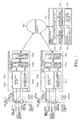
- Figure 1 is a system layout diagram of a circuit breaker switching control system according to a first embodiment of the present invention.
- 100a to 100n are circuit breaker switching control sections
- 500 is a communication network
- 700 is a setting control section, these being the major constituent sections of a circuit breaker switching control system.
- 1000a to 1000n are main circuits
- 1100a to 1100n are circuit breakers
- 1200a to 1200n are current transformers
- 1300a to 1300n are potential transformers (or instrumentation transformers).
- Other disconnecting switches (or interrupters) and grounding switches etc are not shown.
- the usual items of equipment constituting a substation switching device are connected with the main circuits 1000a to 1000n.
- 2000a to 2000n are upper-level devices, such as a protective relay device or BCU (Bay Control Unit).
- circuits may refer to any circuits within the substation such as for example transmission line circuits, transformer circuits, reactor circuits, or capacitor bank circuits.
- the circuit breaker switching control section 100 comprises a signal input section 120, switching control calculation processing section 140, switching command control section 160 and communication calculation processing section 180.
- the signal input section 120 inputs for example the power system voltage, main circuit current and various circuit breaker state quantities such as the circuit breaker temperature, control voltage, and operating pressure.
- the switching control calculation processing section 140 performs switching control calculation processing for turning on or turning off the circuit breaker in a desired phase of the power system voltage or main circuit current.
- the switching command control section 160 outputs to the circuit breaker 1100 an opening command signal whose delay is controlled or a closure command signal whose delay is controlled.
- the communication calculation processing section 180 exchanges various types of information such as state quantities of the circuit breaker with the setting control section 700 through the communication network 500.
- FIG. 2 is a detailed block diagram of the circuit breaker switching control section 100.
- the circuit breaker switching control section 100 is described in further detail with reference to Figure 2 .
- 210, 220 and 230 which are enclosed by the double-dotted chain lines, are the individual circuit boards on which the various constituent elements are mounted. Mutual connection between this circuit board 210, circuit board 220 and circuit board 230 is effected by means of an I/O bus 101 and DPRAM bus 102.
- the circuit board 210 is constituted by one circuit board for each phase: three such circuit boards 210_A, 210_B and 210_C are mounted in the circuit breaker switching control section 100.
- the symbol suffixes _A, _B and _C respectively indicate the A phase, B phase and C phase, but if there is no particular need to distinguish between the A phase, B phase and C phase, the symbol suffixes _A, _B and _C are omitted. It should be noted that any construction of the constituent elements of the circuit breaker switching control section 100 in terms of circuit board layouts other than that of Figure 2 could be adopted, so long as the function of the circuit breaker switching control section 100 described below is satisfied. Also, the mutual connection between the circuit boards could be constituted by connection means other than those shown in Figure 2 .
- the constituent elements mounted on the circuit board 210 are the signal input section 120, switching command control section 160 and I/O bus interface 211.
- the signal input section 120 mounted on the substrate 210 is constituted by for example an AC input circuit 121, sensor input circuit 122, DI input circuit 123, and input control section 124.
- the main circuit current signal and power system voltage signal etc are input to the AC input circuit 121 from for example a current transformer 1200 and instrumentation transformer 1300.
- a circuit breaker control voltage signal, a temperature signal from a temperature sensor, a pressure signal from an operating pressure sensor and a stroke signal from a stroke sensor are input to the sensor input circuit 122 for measuring the state quantities of the circuit breaker.
- the AC input circuit 121 and sensor input circuit 122 comprise for example an insulating circuit or analogue filter (typically a low-pass filter), sample-hold circuit, multiplexer and analogue-digital converter, not shown.
- This AC input circuit 121 and sensor input circuit 122 input as analogue information for example the main circuit current signal, power system voltage signal and sensor signals such as pressure signals, hold these for a prescribed sampling interval, and then convert these into digital quantities.
- a circuit construction could be adopted in which for example the sample-hold circuit and multiplexer are omitted and an analogue-digital converter is provided for each input signal, or a construction could be adopted such as for example an analogue-digital converter incorporating a sample-hold circuit.
- the input circuit construction could be altered, depending on the control algorithm adopted, without necessarily needing to input all the electrical quantities indicated in this embodiment, such as the main circuit current signal, power system voltage signal and sensor signals such as pressure signals.
- the DI (digital) input circuit 123 inputs for example circuit breaker switching command signals from the circuit breaker contact a or circuit breaker contact b, or an upper level device 2000 such as a protective relay device or BCU and other digital signals. These input signals indicate the state quantities of the circuit breaker.
- the DI input circuit 123 inputs digital input quantities that are sampled with a prescribed sampling interval by a sample-hold circuit, not shown, or the like and held.
- the input control section 124 is a logic circuit constituted by for example a PLD (Programmable Logical Device) or FPGA (Field Programmable Gate Array).
- the input control section 124 controls the actuation timing of the sample-hold circuits, multiplexer and analogue-digital converter of for example the AC input circuit 121 and sensor input circuit 122 and DI input circuit 123.
- the input control section 124 also controls data transmission when the main circuit current signal, power system voltage signal, sensor signals such as pressure, contact a or contact b of the circuit breaker, or digital data such as switching command signals are transmitted to the switching control calculation processing section 140 through the I/O bus interface 211.
- the switching command control section 160 mounted on the circuit board 210 comprises for example a switching command output control processing section 161 and switching command output section 162.
- the switching command output control processing section 161 is a logic circuit constituted by for example a PLD (Programmable Logical Device) or FPGA (Field Programmable Gate Array) and incorporates a hardware counter.
- This switching command output control processing section 161 receives a synchronization delay counter value that is transmitted from the switching control calculation processing section 140 via the I/O bus interface 211 and executes control of the counter with a prescribed synchronization delay with respect to the received count value. After this, this switching command output control processing section 161 outputs a trigger signal in respect of the switching command output section 162.
- the switching command output section 162 is typically constituted by a semiconductor switch such as an FET or IGBT: ON actuation of this semiconductor switch is effected in response to the trigger signal from the switching command output control processing section 161.
- ON actuation of the switching command output section 162 is performed, a switching command signal (circuit breaker drive current) of the circuit breaker under synchronized switching control flows to the circuit breaker drive coil 1110, performing opening or closing actuation of the circuit breaker.
- a switching control calculation processing section 140 is mounted on the circuit board 220 as a constituent element.
- the switching control calculation processing section 140 comprises for example a switching control calculation MPU (microprocessor) 141, RAM 142, Flash ROM (or rewritable non-volatile memory such as an EEPROM) 143, DPRAM (dual port RAM) 144, or real-time clock 145: these are mutually connected through a local bus 222.
- MPU microprocessor
- RAM 142 random access memory
- Flash ROM or rewritable non-volatile memory such as an EEPROM
- DPRAM dual port RAM
- real-time clock 145 are mutually connected through a local bus 222.
- the local bus 222 is constituted by an ordinary parallel bus such as the independent parallel bus of the hardware employed, or PCI bus, compact PCI bus, or VME bus.
- the I/O bus interface 221 that is connected with the local bus 222 is the interface of the I/O bus 101 (typically a parallel transmission medium).
- This I/O bus 101 is a data transmission path for mutual communication of data between the switching control calculation processing section 140 and signal input section 120 and switching command control section 160.
- the communication calculation processing section 180 is mounted on the circuit board 230 as a constituent element.
- the communication calculation processing section 180 comprises for example a communication calculation MPU (microprocessor) 181, RAM 182, Flash POM (or rewritable non-volatile memory such as an EEPROM) 183, and a communication interface 184: these are mutually connected to a local bus 232.
- MPU microprocessor
- RAM random access memory
- Flash POM or rewritable non-volatile memory such as an EEPROM
- the local bus 232 is constituted by an ordinary parallel bus such as the independent parallel bus of the hardware employed, or PCI bus, compact PCI bus, or VME bus.
- the communication interface 184 is an interface for connection with the communication network 500. It should be noted that, although, in Figure 2 , the communication calculation MPU 181 and communication interface 184 are connected through the local bus 232, they could be connected by a dedicated local bus.
- the switching control calculation MPU 141 of the switching control calculation processing section 140 and the communication calculation MPU 181 of the communication calculation processing section 180 are connected through the DPRAM bus 102 in order to mutually exchange data.
- the DPPAM bus 102 effects connection through a DPRAM 144 between the local bus 222 of the switching control calculation processing section 140 and the local bus 232 of the communication calculation processing section 180.
- a layout is adopted in which the DPRAM 144 is arranged at the switching control calculation processing section 140, the DPRAM 144 could be arranged at the communication calculation processing section 180.
- a dedicated parallel bus such as a PCI bus, compact PCI bus, or VME bus, or a dedicated serial bus could be employed.
- the I/O bus 101 is the interface for mutual communication of data between the switching control calculation processing section 140 and the signal input section 120 and the switching command control section 160.
- the I/O bus 101 is typically a parallel transmission medium: an ordinary parallel bus such as a PCI bus, contact PCI bus or VME bus may be adopted, or an independent parallel bus of the hardware employed may be adopted. If an independent parallel bus is employed, it may be arranged for the switching control calculation processing section 140 to exchange the synchronization delay count value etc using a dedicated line.
- a construction in which the functionality/construction of the circuit board 230 is included in the circuit board 220 may for example be a construction in which the switching control calculation processing section 140 and communication calculation processing section 180 are collected on a single circuit board, or in which a single common MPU is employed for the switching control calculation MPU 141 and communication calculation MPU 181. In this case, the RAM and FROM etc are shared, and a DPRAM is unnecessary. Also, as a further modified example of the construction of the circuit breaker switching control section 100, a construction may be adopted in which all or some of the I/O buses 101 are replaced by serial transmission media.
- FIG 3 is an example of the layout of the communication network of a circuit breaker switching control system according to the first embodiment of the present invention.
- the communication network 500 will be described in detail with reference to Figure 3 .
- an Ethernet LAN 510 and wide area network 520 are employed as the specific communication means of the communication network 500.
- a local-range circuit breaker switching control section 100 in this substation and a setting control section 700 are connected by the Ethernet LAN 510.
- the switching control section 100_A_1 to 100_A_n of the substation A circuit breaker 10_A, and setting control section 700_A are connected by means of the Ethernet LAN 510_A.
- the switching control section 100_Z_1 to 100_Z_n of the substation Z circuit breaker 10_Z, and setting control section 700 _Z are connected by means of the Ethernet LAN 510_Z.
- the suffixes of the symbols for example _A_n indicates the circuit breaker n of the substation A. If there is no particular need to distinguish between these stations or circuit breakers, the symbol suffixes _A_n etc are omitted.
- the Ethernet LAN 510 whereby the circuit breaker switching control section 100 and setting control section 700 of the stations 10 are connected is mutually connected with the wide area network 520 through a router or gateway 530.
- the setting control section 700 of for example the power station 20, corresponding to a control location at a higher level than the power station is connected with this wide area network 520.
- the setting control section 700_ ⁇ of the ⁇ power station 20_ ⁇ , and the setting control section 700_ ⁇ of the ⁇ power station 20_ ⁇ are mutually connected by the wide area network 520.
- a local network such as an Ethernet LAN is present in each of the power stations 20 and is connected with the wide area network 520 through a router or gateway.
- all of the circuit breaker switching control sections 100 and setting control sections 700 installed in the substation 10 and power station 20 are mutually connected through the communication network 500.
- Ethernet LAN 510 connection using a twisted pair, as such as 10 BASE-T or 100 BASE-TX, or a connection using optical fiber such as a 100 BASE-FX is employed, and the switching control section 100 and setting control section 700 are mutually connected through a hub such as for example a switching hub or repeater.
- a hub such as for example a switching hub or repeater.
- the wide area network 520 there may be employed for example a network using TCP/IP protocol such as an intranet/Internet, or a circuit switching network such as a telephone circuit.
- the communication network 500 may be constituted solely of for example crossed cables, or a one-to-one connection may be constituted of a single switching control section 100 and a setting control section 700.
- the Ethernet LAN construction, the intranet/Internet construction, and the circuit switched network such as the telephone circuit are of ordinary construction, and a detailed description thereof is therefore omitted.
- the setting control section 700 comprises for example a communication processing section 710, display control processing section 720, setting control processing section 730, set value calculation section 740 and data saving processing section 750.
- a specific constructional example of the setting control section 700 may be realized by an ordinary computer such as a personal computer or workstation.
- the communication processing section 710 may be constituted by for example an ordinary computer Ethernet LAN interface circuit and LAN communication software.
- the display control processing section 720 and setting control processing section 730 are constituted by display/setting/control/data processing software that is implemented by a CPU of an ordinary computer and a display device such as a monitor.
- the set value calculation section 740 is constituted by set value calculation processing software that is implemented by a CPU of an ordinary computer.
- the data saving processing section 750 is constituted by data saving processing software that is implemented by a CPU of an ordinary computer and an external storage device such as hard disk or CD-ROM.
- the setting control section software such as the LAN communication software that is implemented on an ordinary computer, the software that performs display/setting/control/data processing, the software for set value calculation processing, and the data saving software must usually be specially developed in accordance with the computer hardware construction employed or operating system, and related software, but ordinary software may be employed for some of this software.
- the setting control section 700 is implemented by installing setting control section software in an ordinary computer tat satisfies the necessary operating conditions such as an Ethernet LAN interface circuit, a CPU capable of implementing the setting control section software, and an external storage device such as a hard disk.
- an ordinary computer on which setting control section software is installed is employed for the setting control section 700.
- a plurality of setting control sections 700 are installed at each substation 10 or power station 20 and a system according to the present invention may be constituted using this plurality of setting control sections 700.
- this plurality of setting control sections 700 and plurality of circuit breaker switching control sections 100a to 100n may be mutually connected through the communication network 500.
- the setting control section 700 may be implemented on dedicated hardware and the other portions (specifically, the communication processing section 710, display control processing section 720, setting control processing section 730, set value calculation section 740 and data saving processing section 750 etc) may be constituted by software running on dedicated hardware.
- circuit breaker switching control section 100 The operation of the circuit breaker switching control section 100 is described below.
- synchronized switching control is performed as follows. First of all, a circuit breaker switching command signal from an upper-level device 2000 such as a protective relay device or BCU is input to the switching command control section 160 of the circuit breaker switching control section 100. After the lapse of a prescribed delay time from input of the switching command signal, the semiconductor switch of the switching command output section 162 is turned ON, with the result that a switching command signal (circuit breaker drive current) is output, subject to synchronized switching control, in respect of the circuit breaker drive coil 1110.
- an upper-level device 2000 such as a protective relay device or BCU
- the decision as to whether or not the prescribed delay time has elapsed is performed by the switching command output control processing section 161 provided in the switching command control section 160 starting counting from the input time of the switching signal, when the count has reached the synchronization delay count value. Also, the prescribed delay time, i.e. the synchronization delay count value, is transmitted to the switching command output control processing section 161 of the switching command control section 160 via the I/O bus 101 after being calculated by the switching control calculation MPU 141 of the switching control calculation processing section 140.
- the hardware counter of the switching command output control processing section 161 of the switching command control section 160 turns the semiconductor switch of the switching command output section 162 ON with a prescribed timing, by counting this synchronization delay count value.
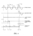
- FIG. 4 is a timing chart example of the method of closing control of the circuit breaker switching control system of the first embodiment of the present invention.
- the synchronized closing control algorithm of the circuit breaker switching control section 100 will now be described in detail with reference to Figure 4 .
- the meaning of the various symbols used in the Figure is as follows.
- the switching command control section 160 waits for the timing t zero of the next zero-cross point of the bus-side voltage.
- the synchronized closing delay time T delay is then calculated, under the assumption that the circuit breaker 1100 should close at a prescribed phase (the timing of t close in Figure 4 ) of the power system voltage (bus-side voltage), once the closure command signal, that performs synchronized closing control of the circuit breaker 1100, is output, after the lapse of a delay time of the synchronized closing delay time T delay from the timing t zero of this zero-Cros point.
- the synchronized closing delay time T delay is calculated by the switching control calculation MPU 141 of the switching control calculation processing section 140.
- the synchronized closing delay time T delay is obtained by the following expression using the time T target from the zero-cross point to the target turn-on phase (this is the electrical target turn-on phase i.e. the timing of T make in Figure 4 ), the pre-arcing time T pre-arcing corresponding to the target turn-on phase, the closing actuation time T closing of the circuit breaker, and the power system period T freq .
- T delay T freq + T target + T pre - arcing - T closing % T freq ⁇ 0 ⁇ T delay ⁇ 2 ⁇ T freq
- T cloging % T freq the remainder of T closing /T freq
- T pre-arcing V make / RDDS .
- the circuit breaker closing actuation time T ciosing varies depending on the circuit breaker temperature, control voltage, operating pressure, and interval between actuations.
- the circuit breaker closing actuation time T closing must therefore be constantly corrected in accordance with conditions such as the circuit breaker temperature, control voltage, operating pressure and interval between actuations.
- the data of the circuit breaker pressure temperature, control voltage and operating pressure are constantly acquired by the signal input section 120.
- the switching control calculation MPU 141 of the switching control calculation section 140 can therefore perform correction calculation of the closing actuation time T closing based on the circuit breaker temperature, control voltage, and operating pressure.
- the correction calculation of the closing actuation time T closing based on the circuit breaker temperature, control voltage, and operating pressure can be performed by calculation based on correction data as shown by for example the circuit breaker temperature characteristic of Figure 5(a) , the circuit breaker control voltage characteristic of Figure 5(b) , or the circuit breaker operating pressure characteristic of Figure 5(c) .
- a real-time clock 145 is mounted on the switching control calculation processing section 140, so that the date and time of actuation of the circuit breaker on the previous occasion can be acquired. Consequently, the interval between circuit breaker actuations can be calculated by the switching control calculation MPU 141, so correction calculation of the closing actuation time T closing based on the actuation interval can be performed.
- the correction calculation of the closing actuation time T ciosing based on the actuation interval of the circuit breaker can be performed using for example correction data as indicated in the circuit breaker actuation interval characteristic of Figure 5(d) .
- synchronized opening control is generally performed with reference to the zero-cross point of the main circuit current: it is known that it is not necessary to take the pre-arcing time into consideration.
- the synchronized switching control algorithm indicated in this embodiment is merely one example: any other synchronized switching control algorithm may be employed in the present invention.
- a specific example of data acquisition and saving actuation by the circuit breaker switching control section 100 in this embodiment is described below.
- the circuit breaker switching control section 100 executes synchronized switching control of the circuit breaker 1100, data associated with synchronized switching control at this time-point are saved. Specifically, for example the following data are saved.
- the circuit breaker switching control section 100 must perform setting of the necessary set values for synchronized switching control of the circuit breaker 1100. Specifically, for example the following set values are set in the circuit breaker switching control section 100. It should be noted that, in the detailed description and claims of the present invention, "set values" means all the values that are written to the switching control section 100 or other sections and in general includes for example the operating reference values, called “setting values (or stabilization values)" and adjustment values at the characteristics.
- the operation of the setting control section 700 is described below.
- the setting control section 700 has the following main functions.
- the set value calculation section 740 performs calculation of the set values for purposes of synchronized switching control of the circuit breaker 1100. Either completely new set values can be calculated or new set values can be obtained by recalculation by correcting the previously employed set values. Specifically, the set values may be calculated for example as follows.
- values obtained by statistical processing for example average value processing
- values obtained by statistical processing for example average value processing of the measured values of opening actuation time and closing actuation time obtained by actuating the circuit breaker a plurality of times in a factory test or installation test performed on-site are employed as the set values for the circuit breaker opening actuation time and closing actuation time.
- data that reflect the data on circuit breaker actuation after commencement of operation of the substation are employed.
- the set values of the opening actuation time and closing actuation time are newly recalculated, using, as the elements of statistical processing (such as for example average value processing), the measured values of opening actuation time and closing actuation time acquired every time synchronized switching control of the circuit breaker 1100 is executed. These are set in the circuit breaker switching control section 100 as the new set values of the recalculated opening actuation time and closing actuation time.
- the temperature characteristic of the circuit breaker opening actuation time and closing actuation time, the control voltage characteristic, operating pressure characteristic and actuation interval characteristic are typically characteristics that depend on the model of the circuit breaker, and are for example characteristic data as shown in Figure 5 , expressed as the amount of variation of the opening actuation time or closing actuation time with respect to the rated conditions.
- Circuit breakers of the same model have the same characteristics, so in general, the data acquired in for example a model test performed in the factory are employed.
- data that reflect the data on circuit breaker actuation after commencement of operation of the substation are employed.
- the variation of the opening actuation time and closing actuation time with respect to the rated conditions are calculated using the measured values of the opening actuation time and closing actuation time acquired every time synchronized switching control of the circuit breaker 1100 is executed, and the measured values of the circuit breaker temperature, control voltage, operating pressure and actuation interval at that time.
- the set values of the temperature characteristic, control voltage characteristic, operating pressure characteristic and actuation interval characteristic are newly recalculated, using, as the elements of statistical processing (such as for example average value processing), the measured values of the variation of opening actuation time and closing actuation time acquired in this way. These are set in the circuit breaker switching control section 100 as the new set values of the recalculated temperature characteristic, control voltage characteristic, operating pressure characteristic and actuation interval characteristic.
- circuit breakers of the same model have the same characteristics in respect of the temperature characteristic of the circuit breaker opening actuation time and closing actuation time, the control voltage characteristic, operating pressure characteristic and actuation interval characteristic. Consequently, the accuracy of the set values of the recalculated temperature characteristic, control voltage characteristic, operating pressure characteristic and actuation interval characteristic can be further improved by employing data obtained from a circuit breaker switching control section 100 that is employed in a plurality of circuit breakers of the same model connected with a communication network 500 in recalculation (for example average value processing).
- Figure 6 shows examples of the set values of the recalculated temperature characteristic, control voltage characteristic, operating pressure characteristic and actuation interval characteristic.
- the dotted lines in Figure 6 represent the characteristic data that are conventionally set in the circuit breaker switching control section 100.
- the continuous lines in Figure 6 show the set values of the recalculated temperature characteristic, control voltage characteristic, operating pressure characteristic and actuation interval characteristic.
- the set values in accordance with the continuous line are newly set in the circuit breaker switching control section 100.
- the rate of decay of dielectric strength (RDDS) of the circuit breaker may also be recalculated by the set value calculation section 740 and reset in the circuit breaker switching control section 100.
- RDDS dielectric strength
- circuit breaker switching control system according to the present embodiment has the following beneficial effects.
- Figure 7 is a system layout diagram of a circuit breaker switching control system according to a second embodiment of the present invention.
- 100a to 100n in Figure 7 are circuit breaker switching control sections; 600 is a wireless communication network; and 700 is a setting control section: these are the main constituent parts of a circuit breaker switching control system according to the second embodiment.
- Wireless communication means 610a to 610n are incorporated in communication calculation processing sections 180 of the circuit breaker switching control sections 100a to 100n in Figure 7 .
- the wireless communication means 610 may replace all or part of the communication interface 184 of the first embodiment shown in Figure 2 .
- the wireless communication means 610 and a wired communication interface 184 may be employed together. Otherwise, the detailed construction of the circuit breaker switching control section 100 is the same as that of the first embodiment, so further description thereof may be dispensed with.
- a wireless communication processing section 620 is incorporated in the setting control section 700 of Figure 7 .
- the wireless communication processing section 620 is constituted by example an ordinary computer wireless LAN interface circuit and wireless LAN communications software.
- the wireless communication processing section that 620 may replace all or part of the communication processing section 710 of the first embodiment shown in Figure 1 .
- the wireless communication processing section 620 and a wired communication processing section 720 may be employed together i.e. an ordinary computer wireless LAN interface circuit and wired Ethernet LAN interface may be employed together. Otherwise, the detailed construction of the setting control section 700 is the same as that of the first embodiment, so further description thereof may be dispensed with.
- An example construction of the wireless communication network 600 of Figure 7 is a wireless communication network that connects the setting control section 700 and circuit breaker switching control sections 100a to 100n in the local range of for example a substation by means of a wireless LAN.
- a communication network is constituted solely by a wireless communication network 600, but it would also be possible to combine a wired communication network 500 and wireless communication network 600 using for example a media converter or hub.
- the wireless communication network 600 may be connected with a broadband network using for example a repeater or switching hub capable of connection with a wireless LAN.
- a layout could also be adopted in which a single circuit breaker switching control section 100 and setting control section 700 are connected wirelessly in one-to-one fashion using a wireless communication network 600.
- the wireless communication processing section 620 was incorporated in the setting control section 700
- a system layout could also be adopted in which the wireless communication processing section 620 is provided outside the setting control section 700.
- the ordinary computer constituting the setting control section 700 may be identical with that employed in the first embodiment, and the wireless LAN device and ordinary computer may be connected using for example a wired Ethernet LAN and USB interface.
- the communication network is a wireless network.
- the circuit breaker switching control section 100 and setting control section 700 are wirelessly connected, the labor involved in laying wired cables can be dispensed with.
- the circuit breaker switching control system is mounted on an already-installed switching device, although application in locations where laying of cables is difficult might be thought to be problematical, in such cases, by application of the present embodiment, laying of cables becomes unnecessary, so the work is facilitated and becomes economic.
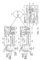
- FIG 8 is a system layout diagram of a circuit breaker switching control system according to a third embodiment of the present invention.
- 100a to 100n are circuit breaker switching control sections
- 500 is a communication network
- 700 is a setting control section.
- the construction of these items is the same as in the case of the circuit breaker switching control system of the first embodiment, so a detailed description thereof may be dispensed with.
- circuit breaker switching control system of the first embodiment The points of difference between the circuit breaker switching control system of the first embodiment and the circuit breaker switching control system of the third embodiment are as follows.
- circuit breaker switching control system of the third embodiment With the circuit breaker switching control system of the third embodiment, the same actions as in the case of the first embodiment and second embodiment can be obtained, and, in addition, the following actions are obtained.
- the communication calculation MPU 181 provided in the communication calculation processing section 180 of the circuit breaker switching control section 100 runs web server software 800.
- the web server 800 accumulates for example the following synchronized switching control-related data in the form of an HTML document or XML document.
- the web server 800 transmits these synchronized switching control-related data to the setting control section 700 through a communication network 500 such as the Internet or intranet.
- the setting control section 700 can execute recalculation processing and resetting processing of the set values of the circuit breaker switching control section 100 utilizing for example JavaScript, using the web browser 810 as an HMI (Human Machine Interface).
- the recalculated set values that are input to the web browser 810, or recalculated set values that were saved in the form of for example a file can be transmitted to the web server 800 of the communication calculation processing section 180 through a communication network 500 such as the Internet or an intranet.
- the communication calculation processing section 180 saves the recalculated set values transmitted to the web server 900 in a Flash ROM 183 (see Figure 2 ).
- the synchronized switching control-related data or current set values can be displayed for example in the form of a table on the web browser 810.
- the waveform data can be displayed as a graph using for example JavaScript.
- the operator can peruse the synchronized switching control-related data or current set values etc, or set recalculated set values in the circuit breaker switching control section 100, using the web browser 810 as an HMI.
- the operator can save received synchronized switching control-related data or current set values in a data saving processing section 750 constituted by an external storage device such as a hard disk, using the web browser 810 as an HMI.
- the same beneficial effects as in the case of the first embodiment and second embodiment are obtained, and, in addition, the following beneficial effects are obtained.
- operator HMI software commercially available web browser software such as for example Internet Explorer may be employed. Since the operator does not need to install special-purpose communication software or maintenance software in the setting control section 700 (computer or the like for HMI use), it is not necessary for the manufacturer to supply the user with special-purpose communication software and maintenance software in the form of a CD-ROM or the like.
- the characteristic feature of the construction of the fourth embodiment is the installation of processing software for calculating the rate of decay of dielectric strength (RODS) of the circuit breaker, as a subfunction of the set value calculation section 740 of the setting control section 700.
- RODS rate of decay of dielectric strength
- Figure 9 is a diagram given in explanation of a method of calculating the rate of decay of dielectric strength (RDDS) in a circuit breaker switching control system according to the fourth embodiment of the present invention, showing a timing chart of the circuit breaker closing actuation, the main circuit current rise timing, and the signal from the stroke sensor.
- RDDS rate of decay of dielectric strength
- the circuit breaker rate of decay of dielectric strength is calculated as the gradient (or grade) linking the power system voltage peak value Vm of the timing with which the circuit breaker is electrically turned on, and the difference between the power system voltage phase ⁇ m of the timing with which the circuit breaker is electrically turned on and the power system voltage phase ⁇ c of the timing with which the circuit breaker is mechanically closed.
- RDDS Vm / ⁇ c - ⁇ m
- the timing with which the Circuit breaker is electrically turned on is calculated as the timing with which the main circuit current starts to flow.
- methods of detecting the timing with which the main circuit current starts to flow there may be employed for example the method of detecting the timing with which the main circuit current exceeds a preset threshold value, or there may be employed the timing with which a harmonic component extracted using a high-pass filter or band-pass filter is detected, or some other method.
- ⁇ m can be calculated by converting the timing with which the circuit breaker is electrically turned on, which is thus measured, into the power system voltage phase. Also, the power system voltage peak value Vm at this timing can be simultaneously calculated.
- the timing with which the circuit breaker is mechanically closed is measured using the output signal of a stroke sensor.
- the timing with which the circuit breaker is mechanically closed means the timing with which the contacts of the circuit breaker become ON. As shown in Figure 9 , the timing with which the contacts of the circuit breaker become ON corresponds in a one-to-one fashion with the output signal of the stroke sensor. Consequently, the timing with which the circuit breaker is mechanically closed can be measured using the output signal of the stroke sensor by measuring beforehand the output value of the stroke sensor at the timing with which the circuit breaker contacts become ON, in for example a factory test.
- ⁇ c can be calculated by converting the timing with which the circuit breaker is mechanically closed, measured in this way, to the power system voltage phase. It should be noted that this timing with which the circuit breaker is mechanically closed could also of course be measured based on the actuation of the auxiliary contact of the circuit breaker, or some other method could be employed.
- the circuit breaker rate of decay of dielectric strength (RDDS) is usually not disclosed and is the data item that is most difficult to obtain by a third party other than the manufacturer of the circuit breaker main unit. Also, even manufacturers of circuit breaker main units frequently do not always measure the rate of decay of dielectric strength (RODS). With this embodiment, measurement of the rate of decay of dielectric strength (RDDS) can easily be carried out: this can therefore contribute to improving the accuracy of synchronized switching control.
- Figure 10 is a system layout diagram of a circuit breaker switching control system according to a fifth embodiment of the present invention.
- the detailed construction of the circuit breaker switching control section 100 in Figure 10 is the same as in the first embodiment, so further description thereof may be dispensed with.
- a set value monitoring processing section 760 is provided as a new structural element. Otherwise, the detailed construction of the setting control section 700 is the same as in the case of the first embodiment, so further description thereof may be dispensed with.
- a system layout employing a wireless communication network 600 may be employed as the communication means between the circuit breaker switching control section 100 and the setting control section 700.
- a system layout may be adopted in which a web server 800 is installed in the communication calculation MPU 181 of the communication calculation processing section 180 of the circuit breaker switching control section 100 and a web browser 810 is installed in the setting control section 700.
- circuit breaker switching control system of the fifth embodiment in addition to the same operations as in the case of the first to the fourth embodiments, the following operations are obtained.
- the circuit breaker switching control section 100 executes synchronized switching control of the circuit breaker 1100
- synchronized switching control - related data are transmitted from the circuit breaker switching control section 100 to the setting control section 700.
- the set value calculation section 740 of the setting control section 700 then performs recalculation of the set values, and saves the results in the data saving processing section 750.
- the set value monitoring processing section 760 of the setting control section 700 monitors the recalculated set values saved in the data saving processing section 750. When the difference between the set value that is currently set in the circuit breaker switching control section 100 and the recalculated set value exceeds a preset threshold value, the user is notified of this fact and processing is performed to transmit the recalculated set value to the circuit breaker switching control section 100.
- a construction may be adopted in which transmission processing of recalculated set values is performed automatically, or a construction may be adopted in which transmission is performed in accordance with a decision made by the user as to whether transmission is necessary or not. Also, a construction may be adopted in which the only items, of the recalculated set values, which are transmitted, are those deemed to be necessary by the user.
- the same beneficial effects are obtained as in the case of the first to the fourth embodiments; in addition, the following beneficial effects are also obtained.
- data such as the opening actuation time and closing actuation time and rate of decay of dielectric strength (RDDS)
- the set values of the synchronized switching control device must be revised in response to changes in the circuit breaker main unit over the years; in this embodiment, whether or not there is a need for revision of these data due to changes over the years is automatically detected and the user is notified accordingly. Consequently, updating of the set values in relation to these data can be performed easily and reliably and, as a result, stable, high-accuracy synchronized switching control can be implemented over a long period.
Landscapes
- Engineering & Computer Science (AREA)
- Power Engineering (AREA)
- Keying Circuit Devices (AREA)
- Remote Monitoring And Control Of Power-Distribution Networks (AREA)
- Driving Mechanisms And Operating Circuits Of Arc-Extinguishing High-Tension Switches (AREA)
Abstract
Description
- The present invention relates to a circuit breaker switching control system for turning on or turning off a circuit breaker at a desired phase of the power system voltage or main circuit current. In particular, it relates to technology for calculating the delay time of the power system voltage or main circuit current with respect to the zero-cross point, based on the circuit breaker switching actuation time and power system period, and for performing circuit breaker switching operation in accordance with this delay time.
- Techniques for controlling the opening or closing timing of a power circuit breaker in order to prevent generation of transient phenomenon in power systems or power equipment are already known. Such techniques for controlling the opening or closing timing of a circuit breaker are termed "synchronized switching control". An example is ""controlled switching of HVAC circuit circuit breakers. Guide for application lines, reactors, capacitors, transformers. SCl3", ELECTRA No. 183 P. 43 (1999)" (hereinbelow referred to as non-patent reference 1)". In such a device that performs synchronized switching control, the closing or closing actuation time of the circuit breaker is detected and a synchronization delay time in respect of the opening or closure command signal of the circuit breaker is calculated, and the output timing of the opening or closure command signal is controlled in accordance with this calculated delay time.
- However, the opening actuation time and closing actuation time of the circuit breaker vary depending on environmental conditions such as the ambient temperature or control voltage of the circuit breaker. The necessity of a function for estimating variation of the opening actuation time and closing actuation time in a device that performs synchronized switching control of a circuit breaker is discussed in
non-patent reference 1. - For example, in the prior art disclosed in Laid-open Japanese Patent Application No.
Tokkai 2001-57135 patent reference 1, the variation of the opening actuation time or closing actuation time of the circuit breaker (this is called the actuation interval characteristic of the circuit breaker) is estimated, using the actuation interval of the circuit breaker. - Also, in the prior art disclosed in Laid-open Japanese Patent Application No.
Tokkai 2001-135205 - However, in order to estimate the changes in the circuit breaker opening actuation time or closing actuation time based on the circuit breaker ambient temperature (hereinafter sometimes may be called the ambient temperature of the circuit breaker, others are the same), control voltage, operating hydraulic pressure and actuation interval etc, as in the prior art of
patent reference 1 or patent reference 2, characteristic data such as the circuit breaker temperature characteristic, control voltage characteristic, hydraulic pressure characteristic and actuation interval characteristic, are necessary. Although, for these circuit breaker characteristic data, typically the same data can be employed if the model of circuit breaker used is the same, when the model of circuit breaker is different, the characteristic data are different for each model. Consequently, for each model of circuit breaker, various types of characteristic data must be measured beforehand in the model testing etc that is performed at the development stage, and these characteristic data must then be set beforehand as set values in the circuit breaker synchronized switching control device. By "the same model" is meant that the electrical characteristics and mechanical characteristics etc that are required in synchronized switching control are the same, excluding individual manufacturing variations. - Also, as stated in
patent reference 1 etc, control taking into account the pre-arcing characteristic of the circuit breaker in synchronized closing control is indispensable. The pre-arcing characteristic must be calculated using the rate of decay of dielectric strength (RDDS), which is different for each model of circuit breaker. Consequently, the rate of decay of dielectric strength (RIDS) must be measured beforehand in the model testing etc that is performed on circuit breaker development, and this rate of decay of dielectric strength (RDDS) set beforehand in the circuit breaker synchronized switching control device. - If the manufacturer of the circuit breaker main unit and the manufacturer of the circuit breaker synchronized switching control device are the same, it is easy to set the necessary data such as the temperature characteristic, control voltage characteristic, hydraulic characteristic, actuation interval characteristic and rate of decay of dielectric strength (RDDS) etc of the circuit breaker in question in the synchronized switching control device of the circuit breaker prior to shipping. However, these data are typically difficult to acquire by a third party other than the manufacturer of the circuit breaker main unit. Consequently, when the manufacturer of the circuit breaker main unit and the manufacturer of the circuit breaker synchronized switching control device are different, it is difficult to set these data beforehand in the synchronized switching control device of the circuit breaker prior to shipping.
- Furthermore, even when the manufacturer of the circuit breaker main unit and the manufacturer of the circuit breaker synchronized switching control device are the same, when for example a synchronized switching control device is added to an already-installed old circuit breaker, data such as the temperature characteristic, control voltage characteristic, hydraulic pressure characteristic, actuation interval characteristic and rate of decay of dielectric strength (RDDS) are not necessarily all available. Even if all the data are available, the precision of the data may be insufficient. In such cases, the models of circuit breaker with which a synchronized switching control device may be employed are restricted. Consequently, it is found that the application of a synchronized switching control device to an already-installed circuit breaker is difficult, or that the synchronized switching control device must be replaced when the circuit breaker is replaced.
- Also, considered from the point of view of a user such as a power company, there is a possibility of economic disadvantage associated with the fact that, in power systems in which synchronized switching control is necessary, the purchasing source for the circuit breaker main unit or circuit breaker synchronized switching control device, or both of these, is restricted beforehand.
- Even for circuit breakers of the same model, there are individual differences between circuit breakers in regard to the opening actuation time and closing actuation time under the standard conditions (typically corresponding to the opening actuation time and closing actuation time under the rated conditions) due to factors such as manufacturing variation. Consequently, the opening actuation time and closing actuation time must be measured for each circuit breaker in for example a shipping test and these data must be set in the synchronized switching control device of the circuit breaker prior to commencement of operation of the substation.
- However, the opening actuation time and closing actuation time of the circuit breaker may change over a period of years, due to the effect of the number of times of circuit breaker actuation. Also, the rate of decay of dielectric strength (RDDS) may change over a period of years due to the effect of for example the number of times of interruption of the fault current or the magnitude of the fault current that is interrupted. It is therefore necessary to revise the set values of the synchronized switching control device in regard to data such as the opening actuation time and closing actuation time and rate of decay of dielectric strength (RDDS) in response to change over a period of years of the circuit breaker main unit. However, such revision of the set values was difficult to perform in the case of a conventional synchronized switching control device.
- The present invention was made in view of the above problems. Specifically, an object of the present invention is to provide a circuit breaker switching control system wherein, if data such as the circuit breaker temperature characteristic, control voltage characteristic, hydraulic pressure characteristic, actuation interval characteristic and rate of decay of dielectric strength (PDDS) are not available, these data can be separately measured and easily set in the circuit breaker synchronized switching control device.
- A further object of the present invention is to provide a circuit breaker switching control system wherein the various items of data referred to above can easily be revised in accordance with data acquired after the commencement of operation. Yet a further object of the present invention is to provide a circuit breaker switching control system wherein the various items of data referred to above can easily be revised in response to changes in the circuit breaker over the years.
- In order to achieve the objects described above, a circuit breaker switching control system according to the present invention comprising a circuit breaker switching control section and a setting control section connected with abovementioned circuit breaker switching control section through a communication network is constructed as follows.
- Abovementioned circuit breaker switching control section comprises:
- (a) a signal input section that inputs at least one electrical quantity of the power system voltage or main circuit current, a circuit breaker state quantity, and at least one signal of a circuit breaker opening command signal or closure command signal;
- (b) a switching control calculation processing section that calculates the delay time with respect to the zero-cross point of the power system voltage or main circuit current, based on the circuit breaker switching actuation time and power system period, in order to turn on or turn off the circuit breaker with a desired phase of the power system voltage or main circuit current; and
- (c) a switching command control section that outputs in respect of the circuit breaker an opening command signal or closure command signal with a delay that is controlled in accordance with the delay time that is calculated by abovementioned switching calculation processing section.
- Abovementioned setting control section comprises:
- (d) a setting control processing section that performs setting control of a set value used to correct the switching actuation time of the circuit breaker, in respect of the switching control section of abovementioned circuit breaker;
- (e) a display control processing section of the set value that is set by abovementioned setting control processing section; and
- (f) a set value calculation section that calculates abovementioned set value from the state quantity of the circuit breaker.
- With the present invention constructed as above, by means of the circuit breaker switching control section and at setting control section having a construction as described above,
- (1) the switching control section of abovementioned circuit breaker transmits the state quantity of the circuit breaker acquired by the signal input section to the set value calculation section of abovementioned setting control section through the communication network;
- (2) the set value calculation section of abovementioned setting control section calculates the set value is to be set in the switching control section of abovementioned circuit breaker using the circuit break state quantity that has thus been transmitted;
- (3) abovementioned setting control section transmits the set value calculated by abovementioned set value calculation section through abovementioned communication network to abovementioned circuit breaker switching control section; and
- (4) the switching control calculation processing section that is provided in abovementioned circuit breaker switching control section corrects the switching actuation time of the circuit breaker in accordance with this set value and calculates a delay time with respect to the zero-cross point, in accordance with this corrected switching actuation time and power system period.
- With a circuit breaker switching control system according to the present invention having a construction as described above, the state is acquired from the circuit breaker during operation, this data is transmitted to the setting control section through the network, and the setting control section calculates the set value for correcting the circuit breaker switching actuation time.
- With the present invention, the set values necessary for calculation of the delay time in respect of the zero-cross point of the power system voltage or main circuit current can be determined in accordance with the state quantity that is acquired from the circuit breaker during operation. As a result, the need to acquire the characteristic values etc of the circuit breaker beforehand is eliminated, and determination of the set values becomes easy and precise.
-
-
Figure 1 is a system layout diagram of a circuit breaker switching control system according to a first embodiment of the present invention; -
Figure 2 is a detailed block diagram of a circuit breaker switching control section according to a first embodiment of the present invention; -
Figure 3 is a view showing an example of the layout of a communication network of a circuit breaker switching control system according to a first embodiment of the present invention; -
Figure 4 is a timing chart showing an example of a closing control method of a circuit breaker switching control system according to a first embodiment of the present invention; -
Figure 5 is a graph showing an example of set values of the temperature characteristic, control voltage characteristic, operating pressure characteristic, and actuation interval characteristic of a circuit breaker switching control system according to a first embodiment of the present invention; -
Figure 6 is a graph showing an example of recalculated set values of the temperature characteristic, control voltage characteristic, operating pressure characteristic and actuation interval characteristic of a circuit breaker switching control system according to a first embodiment of the present invention; -
Figure 7 is a system layout diagram of a circuit breaker switching control system according to a second embodiment of the present invention; -
Figure 8 is a system layout diagram of a circuit breaker switching control system according to a third embodiment of the present invention; -
Figure 9 is a diagram of a method of calculation of the rate of decay of dielectric strength in a circuit breaker switching control system according to a fourth embodiment of the present invention; and -
Figure 10 is a system layout diagram of a circuit breaker switching control system according to a fifth embodiment of the present invention. - Embodiments of a circuit breaker switching control system according to the present invention are described below with reference to the drawings. "Ethernet", "Windows" and "Java" used in the various embodiments of the present invention are registered trademarks.
-
Figure 1 is a system layout diagram of a circuit breaker switching control system according to a first embodiment of the present invention. InFigure 1 , 100a to 100n are circuit breaker switching control sections, 500 is a communication network, and 700 is a setting control section, these being the major constituent sections of a circuit breaker switching control system. Also, 1000a to 1000n are main circuits, 1100a to 1100n are circuit breakers, 1200a to 1200n are current transformers, and 1300a to 1300n are potential transformers (or instrumentation transformers). Other disconnecting switches (or interrupters) and grounding switches etc are not shown. The usual items of equipment constituting a substation switching device are connected with themain circuits 1000a to 1000n. 2000a to 2000n are upper-level devices, such as a protective relay device or BCU (Bay Control Unit). - Only a single phase is shown in
Figure 1 , but the present invention may be applied to three-phase circuit breakers and other circuits. Hereinbelow, unless otherwise specified, the present invention is taken to be applied to a three-phase circuit or three-phase circuit breaker. The suffixes a to n of the symbols represent circuits a to n and will be omitted hereinbelow unless they are specially required in the description. These circuits a to n may be different circuits within the same substation or may be different circuits between mutually different stations. "Circuits" according to the present invention may refer to any circuits within the substation such as for example transmission line circuits, transformer circuits, reactor circuits, or capacitor bank circuits. - The main constituent parts of switching control system of a circuit breaker are described in more detail with reference to
Figure 1 . - The circuit breaker switching
control section 100 comprises asignal input section 120, switching controlcalculation processing section 140, switchingcommand control section 160 and communicationcalculation processing section 180. Thesignal input section 120 inputs for example the power system voltage, main circuit current and various circuit breaker state quantities such as the circuit breaker temperature, control voltage, and operating pressure. The switching controlcalculation processing section 140 performs switching control calculation processing for turning on or turning off the circuit breaker in a desired phase of the power system voltage or main circuit current. The switchingcommand control section 160 outputs to the circuit breaker 1100 an opening command signal whose delay is controlled or a closure command signal whose delay is controlled. The communicationcalculation processing section 180 exchanges various types of information such as state quantities of the circuit breaker with the settingcontrol section 700 through thecommunication network 500. - Regarding the various constituent elements of the switching
control section 100 of the circuit breaker, only one phase is illustrated inFigure 1 , but, in fact, the necessary constituents for controlling three-phase circuit breaker are of course present, and this applies in the same way in the description below, unless otherwise specially noted. -
Figure 2 is a detailed block diagram of the circuit breaker switchingcontrol section 100. The circuit breaker switchingcontrol section 100 is described in further detail with reference toFigure 2 . In the embodiment ofFigure 2 , 210, 220 and 230, which are enclosed by the double-dotted chain lines, are the individual circuit boards on which the various constituent elements are mounted. Mutual connection between this circuit board 210,circuit board 220 andcircuit board 230 is effected by means of an I/O bus 101 andDPRAM bus 102. The circuit board 210 is constituted by one circuit board for each phase: three such circuit boards 210_A, 210_B and 210_C are mounted in the circuit breaker switchingcontrol section 100. - The symbol suffixes _A, _B and _C respectively indicate the A phase, B phase and C phase, but if there is no particular need to distinguish between the A phase, B phase and C phase, the symbol suffixes _A, _B and _C are omitted. It should be noted that any construction of the constituent elements of the circuit breaker switching
control section 100 in terms of circuit board layouts other than that ofFigure 2 could be adopted, so long as the function of the circuit breaker switchingcontrol section 100 described below is satisfied. Also, the mutual connection between the circuit boards could be constituted by connection means other than those shown inFigure 2 . - The constituent elements mounted on the circuit board 210 are the
signal input section 120, switchingcommand control section 160 and I/O bus interface 211. Thesignal input section 120 mounted on the substrate 210 is constituted by for example an AC input circuit 121, sensor input circuit 122, DI input circuit 123, and input control section 124. The main circuit current signal and power system voltage signal etc are input to the AC input circuit 121 from for example acurrent transformer 1200 and instrumentation transformer 1300. For example a circuit breaker control voltage signal, a temperature signal from a temperature sensor, a pressure signal from an operating pressure sensor and a stroke signal from a stroke sensor are input to the sensor input circuit 122 for measuring the state quantities of the circuit breaker. - The AC input circuit 121 and sensor input circuit 122 comprise for example an insulating circuit or analogue filter (typically a low-pass filter), sample-hold circuit, multiplexer and analogue-digital converter, not shown. This AC input circuit 121 and sensor input circuit 122 input as analogue information for example the main circuit current signal, power system voltage signal and sensor signals such as pressure signals, hold these for a prescribed sampling interval, and then convert these into digital quantities.
- It should be noted that a circuit construction could be adopted in which for example the sample-hold circuit and multiplexer are omitted and an analogue-digital converter is provided for each input signal, or a construction could be adopted such as for example an analogue-digital converter incorporating a sample-hold circuit. Also, the input circuit construction could be altered, depending on the control algorithm adopted, without necessarily needing to input all the electrical quantities indicated in this embodiment, such as the main circuit current signal, power system voltage signal and sensor signals such as pressure signals.
- The DI (digital) input circuit 123 inputs for example circuit breaker switching command signals from the circuit breaker contact a or circuit breaker contact b, or an upper level device 2000 such as a protective relay device or BCU and other digital signals. These input signals indicate the state quantities of the circuit breaker. The DI input circuit 123 inputs digital input quantities that are sampled with a prescribed sampling interval by a sample-hold circuit, not shown, or the like and held.
- The input control section 124 is a logic circuit constituted by for example a PLD (Programmable Logical Device) or FPGA (Field Programmable Gate Array). The input control section 124 controls the actuation timing of the sample-hold circuits, multiplexer and analogue-digital converter of for example the AC input circuit 121 and sensor input circuit 122 and DI input circuit 123. The input control section 124 also controls data transmission when the main circuit current signal, power system voltage signal, sensor signals such as pressure, contact a or contact b of the circuit breaker, or digital data such as switching command signals are transmitted to the switching control
calculation processing section 140 through the I/O bus interface 211. - The switching
command control section 160 mounted on the circuit board 210 comprises for example a switching command output control processing section 161 and switching command output section 162. - The switching command output control processing section 161 is a logic circuit constituted by for example a PLD (Programmable Logical Device) or FPGA (Field Programmable Gate Array) and incorporates a hardware counter. This switching command output control processing section 161 receives a synchronization delay counter value that is transmitted from the switching control
calculation processing section 140 via the I/O bus interface 211 and executes control of the counter with a prescribed synchronization delay with respect to the received count value. After this, this switching command output control processing section 161 outputs a trigger signal in respect of the switching command output section 162. - It should be noted that, although, in the construction of
Figure 2 , a construction was adopted in which a hardware counter was incorporated in the switching command output control processing section 161, depending on the control algorithm adopted, the hardware counter could be dispensed with. - The switching command output section 162 is typically constituted by a semiconductor switch such as an FET or IGBT: ON actuation of this semiconductor switch is effected in response to the trigger signal from the switching command output control processing section 161. When ON actuation of the switching command output section 162 is performed, a switching command signal (circuit breaker drive current) of the circuit breaker under synchronized switching control flows to the circuit breaker drive coil 1110, performing opening or closing actuation of the circuit breaker.
- A switching control
calculation processing section 140 is mounted on thecircuit board 220 as a constituent element. The switching controlcalculation processing section 140 comprises for example a switching control calculation MPU (microprocessor) 141,RAM 142, Flash ROM (or rewritable non-volatile memory such as an EEPROM) 143, DPRAM (dual port RAM) 144, or real-time clock 145: these are mutually connected through alocal bus 222. - The
local bus 222 is constituted by an ordinary parallel bus such as the independent parallel bus of the hardware employed, or PCI bus, compact PCI bus, or VME bus. The I/O bus interface 221 that is connected with thelocal bus 222 is the interface of the I/O bus 101 (typically a parallel transmission medium). This I/O bus 101 is a data transmission path for mutual communication of data between the switching controlcalculation processing section 140 and signalinput section 120 and switchingcommand control section 160. - The communication
calculation processing section 180 is mounted on thecircuit board 230 as a constituent element. The communicationcalculation processing section 180 comprises for example a communication calculation MPU (microprocessor) 181,RAM 182, Flash POM (or rewritable non-volatile memory such as an EEPROM) 183, and a communication interface 184: these are mutually connected to alocal bus 232. - The
local bus 232 is constituted by an ordinary parallel bus such as the independent parallel bus of the hardware employed, or PCI bus, compact PCI bus, or VME bus. Thecommunication interface 184 is an interface for connection with thecommunication network 500. It should be noted that, although, inFigure 2 , thecommunication calculation MPU 181 andcommunication interface 184 are connected through thelocal bus 232, they could be connected by a dedicated local bus. - The switching
control calculation MPU 141 of the switching controlcalculation processing section 140 and thecommunication calculation MPU 181 of the communicationcalculation processing section 180 are connected through theDPRAM bus 102 in order to mutually exchange data. TheDPPAM bus 102 effects connection through aDPRAM 144 between thelocal bus 222 of the switching controlcalculation processing section 140 and thelocal bus 232 of the communicationcalculation processing section 180. It should be noted that, although, in the construction ofFigure 2 , a layout is adopted in which theDPRAM 144 is arranged at the switching controlcalculation processing section 140, theDPRAM 144 could be arranged at the communicationcalculation processing section 180. Also, instead of a layout employing a DPRAM, a dedicated parallel bus such as a PCI bus, compact PCI bus, or VME bus, or a dedicated serial bus could be employed. - The I/
O bus 101 is the interface for mutual communication of data between the switching controlcalculation processing section 140 and thesignal input section 120 and the switchingcommand control section 160. The I/O bus 101 is typically a parallel transmission medium: an ordinary parallel bus such as a PCI bus, contact PCI bus or VME bus may be adopted, or an independent parallel bus of the hardware employed may be adopted. If an independent parallel bus is employed, it may be arranged for the switching controlcalculation processing section 140 to exchange the synchronization delay count value etc using a dedicated line. - It should be noted that, as a modified example of the construction of the circuit breaker switching
control section 100, the same action and effects could be obtained by adopting a construction in which the functionality/construction of thecircuit board 230 is included in thecircuit board 220. A construction in which the functionality/construction of thecircuit board 230 is included in thecircuit board 220 may for example be a construction in which the switching controlcalculation processing section 140 and communicationcalculation processing section 180 are collected on a single circuit board, or in which a single common MPU is employed for the switchingcontrol calculation MPU 141 andcommunication calculation MPU 181. In this case, the RAM and FROM etc are shared, and a DPRAM is unnecessary. Also, as a further modified example of the construction of the circuit breaker switchingcontrol section 100, a construction may be adopted in which all or some of the I/O buses 101 are replaced by serial transmission media. -
Figure 3 is an example of the layout of the communication network of a circuit breaker switching control system according to the first embodiment of the present invention. Thecommunication network 500 will be described in detail with reference toFigure 3 . In this embodiment, as the specific communication means of thecommunication network 500, an Ethernet LAN 510 andwide area network 520 are employed. - In each
substation 10 or the like, a local-range circuit breaker switchingcontrol section 100 in this substation and asetting control section 700 are connected by the Ethernet LAN 510. For example, inFigure 3 , the switching control section 100_A_1 to 100_A_n of the substation A circuit breaker 10_A, and setting control section 700_A are connected by means of the Ethernet LAN 510_A. Likewise, the switching control section 100_Z_1 to 100_Z_n of the substation Z circuit breaker 10_Z, and settingcontrol section 700 _Z are connected by means of the Ethernet LAN 510_Z. Herein, regarding the suffixes of the symbols, for example _A_n indicates the circuit breaker n of the substation A. If there is no particular need to distinguish between these stations or circuit breakers, the symbol suffixes _A_n etc are omitted. - The Ethernet LAN 510 whereby the circuit breaker switching
control section 100 and settingcontrol section 700 of thestations 10 are connected is mutually connected with thewide area network 520 through a router or gateway 530. The settingcontrol section 700 of for example thepower station 20, corresponding to a control location at a higher level than the power station is connected with thiswide area network 520. for example, inFigure 3 , the setting control section 700_α of the α power station 20_α, and the setting control section 700_β of the β power station 20_β are mutually connected by thewide area network 520. It should be noted that, although not shown, a local network such as an Ethernet LAN is present in each of thepower stations 20 and is connected with thewide area network 520 through a router or gateway. Specifically, all of the circuit breaker switchingcontrol sections 100 and settingcontrol sections 700 installed in thesubstation 10 andpower station 20 are mutually connected through thecommunication network 500. - Although not shown in the Figures, for the Ethernet LAN 510, connection using a twisted pair, as such as 10 BASE-T or 100 BASE-TX, or a connection using optical fiber such as a 100 BASE-FX is employed, and the switching
control section 100 and settingcontrol section 700 are mutually connected through a hub such as for example a switching hub or repeater. Also, as thewide area network 520, there may be employed for example a network using TCP/IP protocol such as an intranet/Internet, or a circuit switching network such as a telephone circuit. - In the constructional example of the communication network of
Figure 3 , a construction is adopted in whichsetting control sections 700 are installed at eachsubstation 10; however, a construction could also be adopted in which these settingcontrol sections 700 are arranged only at thepower stations 20. Also, thecommunication network 500 may be constituted solely of for example crossed cables, or a one-to-one connection may be constituted of a singleswitching control section 100 and asetting control section 700. The Ethernet LAN construction, the intranet/Internet construction, and the circuit switched network such as the telephone circuit are of ordinary construction, and a detailed description thereof is therefore omitted. - The setting
control section 700 will now be described in detail with reference toFigure 1 . The settingcontrol section 700 comprises for example acommunication processing section 710, displaycontrol processing section 720, settingcontrol processing section 730, setvalue calculation section 740 and data savingprocessing section 750. A specific constructional example of the settingcontrol section 700 may be realized by an ordinary computer such as a personal computer or workstation. Thecommunication processing section 710 may be constituted by for example an ordinary computer Ethernet LAN interface circuit and LAN communication software. - The display
control processing section 720 and settingcontrol processing section 730 are constituted by display/setting/control/data processing software that is implemented by a CPU of an ordinary computer and a display device such as a monitor. The setvalue calculation section 740 is constituted by set value calculation processing software that is implemented by a CPU of an ordinary computer. The data savingprocessing section 750 is constituted by data saving processing software that is implemented by a CPU of an ordinary computer and an external storage device such as hard disk or CD-ROM. - The setting control section software such as the LAN communication software that is implemented on an ordinary computer, the software that performs display/setting/control/data processing, the software for set value calculation processing, and the data saving software must usually be specially developed in accordance with the computer hardware construction employed or operating system, and related software, but ordinary software may be employed for some of this software.
- As described above, the setting
control section 700 is implemented by installing setting control section software in an ordinary computer tat satisfies the necessary operating conditions such as an Ethernet LAN interface circuit, a CPU capable of implementing the setting control section software, and an external storage device such as a hard disk. In this embodiment, unless specially noted in the following description, an ordinary computer on which setting control section software is installed is employed for thesetting control section 700. - Also, although not illustrated, it is possible to install software for implementing a setting control section respectively on a plurality of ordinary computers arranged at each
substation 10 orpower station 20. If this is done, a plurality of settingcontrol sections 700 are installed at eachsubstation 10 orpower station 20 and a system according to the present invention may be constituted using this plurality of settingcontrol sections 700. In this case, this plurality of settingcontrol sections 700 and plurality of circuit breaker switchingcontrol sections 100a to 100n may be mutually connected through thecommunication network 500. - The setting
control section 700 may be implemented on dedicated hardware and the other portions (specifically, thecommunication processing section 710, displaycontrol processing section 720, settingcontrol processing section 730, setvalue calculation section 740 and data savingprocessing section 750 etc) may be constituted by software running on dedicated hardware. - The operation of a system according to a first embodiment constructed as described above is described below.
- The operation of the circuit breaker switching
control section 100 is described below. - In this embodiment, when the contacts of the circuit breaker 1100 are opened or closed with a prescribed phase of the main circuit current or power system voltage, synchronized switching control is performed as follows. First of all, a circuit breaker switching command signal from an upper-level device 2000 such as a protective relay device or BCU is input to the switching
command control section 160 of the circuit breaker switchingcontrol section 100. After the lapse of a prescribed delay time from input of the switching command signal, the semiconductor switch of the switching command output section 162 is turned ON, with the result that a switching command signal (circuit breaker drive current) is output, subject to synchronized switching control, in respect of the circuit breaker drive coil 1110. - In this case, the decision as to whether or not the prescribed delay time has elapsed is performed by the switching command output control processing section 161 provided in the switching
command control section 160 starting counting from the input time of the switching signal, when the count has reached the synchronization delay count value. Also, the prescribed delay time, i.e. the synchronization delay count value, is transmitted to the switching command output control processing section 161 of the switchingcommand control section 160 via the I/O bus 101 after being calculated by the switchingcontrol calculation MPU 141 of the switching controlcalculation processing section 140. On output of the switching command signal, under synchronization control, in respect of thecircuit breaker 100, the hardware counter of the switching command output control processing section 161 of the switchingcommand control section 160 turns the semiconductor switch of the switching command output section 162 ON with a prescribed timing, by counting this synchronization delay count value. -
Figure 4 is a timing chart example of the method of closing control of the circuit breaker switching control system of the first embodiment of the present invention. The synchronized closing control algorithm of the circuit breaker switchingcontrol section 100 will now be described in detail with reference toFigure 4 . The meaning of the various symbols used in the Figure is as follows. - Tw: zero-cross point waiting time
- Tdelay: synchronized closing delay time
- Ttarget: time from the zero-cross point to the target electrical turn-on phase (Ttarget<Tfreq)
- Tclosing: closing actuation time
- Ta_contact: closing actuation time measured at auxiliary contact (a contact)
- ΔTclosing: error of closing actuation time measured at auxiliary contact (a contact)
- Tfreq: power system period
- Tpre-arcing: pre-arcing time
- Ttotal: total waiting time from input of closure command signal to output of closure command signal
- tcommand: closure command signal input timing
- tzero: timing of next zero-cross point after input of closure command signal
- tcontrol: closure command signal output timing
- tclose: closing timing of mechanical contacts
- tmake: electrical turn-on timing
- After detection of the closure command signal with the timing of tcommand, the switching
command control section 160 waits for the timing tzero of the next zero-cross point of the bus-side voltage. The synchronized closing delay time Tdelay is then calculated, under the assumption that the circuit breaker 1100 should close at a prescribed phase (the timing of tclose inFigure 4 ) of the power system voltage (bus-side voltage), once the closure command signal, that performs synchronized closing control of the circuit breaker 1100, is output, after the lapse of a delay time of the synchronized closing delay time Tdelay from the timing tzero of this zero-Cros point. - The synchronized closing delay time Tdelay is calculated by the switching
control calculation MPU 141 of the switching controlcalculation processing section 140. The synchronized closing delay time Tdelay is obtained by the following expression using the time Ttarget from the zero-cross point to the target turn-on phase (this is the electrical target turn-on phase i.e. the timing of Tmake inFigure 4 ), the pre-arcing time Tpre-arcing corresponding to the target turn-on phase, the closing actuation time Tclosing of the circuit breaker, and the power system period Tfreq.
where (Tcloging % Tfreq) is the remainder of Tclosing/Tfreq
and the pre-arcing time Tpre-arcing is obtained by the following expression using the voltage peak value Vmake at the target turn-on phase and the rate of decay of dielectric strength RDDS.
- The circuit breaker closing actuation time Tciosing varies depending on the circuit breaker temperature, control voltage, operating pressure, and interval between actuations. The circuit breaker closing actuation time Tclosing must therefore be constantly corrected in accordance with conditions such as the circuit breaker temperature, control voltage, operating pressure and interval between actuations.
- As shown in
Figure 2 , the data of the circuit breaker pressure temperature, control voltage and operating pressure are constantly acquired by thesignal input section 120. The switchingcontrol calculation MPU 141 of the switchingcontrol calculation section 140 can therefore perform correction calculation of the closing actuation time Tclosing based on the circuit breaker temperature, control voltage, and operating pressure. The correction calculation of the closing actuation time Tclosing based on the circuit breaker temperature, control voltage, and operating pressure can be performed by calculation based on correction data as shown by for example the circuit breaker temperature characteristic ofFigure 5(a) , the circuit breaker control voltage characteristic ofFigure 5(b) , or the circuit breaker operating pressure characteristic ofFigure 5(c) . - Also, as shown in
Figure 2 , a real-time clock 145 is mounted on the switching controlcalculation processing section 140, so that the date and time of actuation of the circuit breaker on the previous occasion can be acquired. Consequently, the interval between circuit breaker actuations can be calculated by the switchingcontrol calculation MPU 141, so correction calculation of the closing actuation time Tclosing based on the actuation interval can be performed. The correction calculation of the closing actuation time Tciosing based on the actuation interval of the circuit breaker can be performed using for example correction data as indicated in the circuit breaker actuation interval characteristic ofFigure 5(d) . - It may be noted that the same operation may be performed in respect of synchronized opening control. However, synchronized opening control is generally performed with reference to the zero-cross point of the main circuit current: it is known that it is not necessary to take the pre-arcing time into consideration. Also, the synchronized switching control algorithm indicated in this embodiment is merely one example: any other synchronized switching control algorithm may be employed in the present invention.
- A specific example of data acquisition and saving actuation by the circuit breaker switching
control section 100 in this embodiment is described below. When the circuit breaker switchingcontrol section 100 executes synchronized switching control of the circuit breaker 1100, data associated with synchronized switching control at this time-point are saved. Specifically, for example the following data are saved. - · the circuit breaker actuation date and time
- · the main circuit current waveform before and after circuit breaker switching actuation
- · the power system voltage waveform before and after circuit breaker switching actuation
- · the circuit breaker stroke waveform
- · the circuit breaker opening actuation time and closing actuation time
- · the circuit breaker temperature
- · the circuit breaker control voltage
- · the circuit breaker operating pressure
- · other data.
- A specific embodiment of actuation of the data acquisition/saving process is described below.
- (1) Synchronized switching control-related data such as the main circuit current, the power system voltage, the stroke of the circuit breaker, the temperature, the control voltage and the operating pressure acquired by the
signal input section 120 are transmitted to the switching controlcalculation processing section 140 via the I/O bus 101. - (2) The switching
control calculation MPU 141 of the switching controlcalculation processing section 140 converts the synchronized switching control-related data such as the main circuit current, power system voltage, circuit breaker stroke, temperature, control voltage and operating pressure into physical quantities and performs calculation of for example the circuit breaker opening actuation time and closing actuation time and writes the results in theDPRAM 144. - (3) The
communication calculation MPU 181 of the communicationcalculation processing section 180 acquires the synchronized switching control-related data that was written to theDPRAM 144. - (4) The
communication calculation MPU 181 of the communicationcalculation processing section 180 saves the acquired synchronized switching control-related data in theFlash ROM 183. - (5) When a request for acquisition of synchronized switching control-related data is generated in respect of the circuit breaker switching
control section 100 from the settingcontrol section 700, thecommunication calculation MPU 181 of the communicationcalculation processing section 180 transmits the synchronized switching control-related data that was saved in theFlash ROM 183 to thesetting control section 700 via thecommunication network 500. - Next, a specific example of the operation of setting the circuit breaker switching
control section 100 in this embodiment will be described. The circuit breaker switchingcontrol section 100 must perform setting of the necessary set values for synchronized switching control of the circuit breaker 1100. Specifically, for example the following set values are set in the circuit breaker switchingcontrol section 100. It should be noted that, in the detailed description and claims of the present invention, "set values" means all the values that are written to the switchingcontrol section 100 or other sections and in general includes for example the operating reference values, called "setting values (or stabilization values)" and adjustment values at the characteristics. - · the target opening phase and target closing phase
- · the circuit breaker opening actuation time and closing actuation time
- · the circuit breaker rate of decay of dielectric strength (RDDS)
- · the temperature characteristic of the circuit breaker opening actuation time and closing actuation time
- · the control voltage characteristic of the circuit breaker opening actuation time and closing actuation time
- · the operating pressure characteristic of the circuit breaker opening actuation time and closing actuation time
- · the actuation interval characteristic of the circuit breaker opening actuation time and closing actuation time
- · other data
- Specific embodiments of the operation of setting the set values are as follows.
- (1) The
communication calculation MPU 181 of the communicationcalculation processing section 180 saves the set values that are transmitted from the settingcontrol section 700 via thecommunication network 500 in theFlash ROM 183. - (2) The switching
control calculation MPU 141 of the switching controlcalculation processing section 140 acquires the set values from the communicationcalculation processing section 180 through theDPRAM 144. - (3) The switching
control calculation MPU 141 of the switching controlcalculation processing section 140 performs synchronized switching control calculation using the set values that have thus been acquired. - The operation of the setting
control section 700 is described below. The settingcontrol section 700 has the following main functions. - · function of saving the synchronized switching control-related data acquired by the circuit breaker switching
control section 100 - · function of displaying the synchronized switching control-related data acquired by the circuit breaker switching
control section 100 - · function of calculating the set values of the circuit breaker switching
control section 100 - · function of displaying/transmitting the set values of the circuit breaker switching
control section 100 - The function of saving/displaying synchronized switching control-related data acquired by the circuit breaker switching
control section 100 is described below. - (1) Synchronized switching control-related data transmitted via the
communication network 500 from the circuit breaker switchingcontrol section 100 are received by thecommunication processing section 710 of the settingcontrol section 700. - (2) The switching control-related data that are received are saved in a data saving
processing section 750 constituted by an external storage device such as a hard disk and the synchronized switching control-related data are displayed on a display device such as a monitor by a display/control processing section 720 constituted by display/setting/control/data processing software constituting an HMI (Human Interface). - The calculation function and display/transmission function of the set values of the circuit breaker switching
control section 100 are described below. - (1) The set
value calculation section 740 of the settingcontrol section 700 reads the synchronized switching control-related data that are saved in the data savingprocessing section 750. - (2) The set value calculation processing software of the set
value calculation section 740 calculates the set values of the circuit breaker switchingcontrol section 100. - (3) The display/control/
processing section 720 displays on a display device such as a monitor the set values of the circuit breaker switchingcontrol section 100 calculated by the setvalue calculation section 740, using display/setting/control/data processing software constituting an HMI (Human Interface). - (4) The setting/control/
processing section 730 issues a transmission command to the circuit breaker switchingcontrol section 100 to transmit the necessary set values, of the set values of the circuit breaker switchingcontrol section 100 calculated by the setvalue calculation section 740. - (5) The set values in respect of which a transmission command was issued by the setting/control/
processing section 730 are subjected to transmission processing by thecommunication processing section 710 and transmitted to the circuit breaker switchingcontrol section 100 via thecommunication network 500. - Next, the details of the actuation process in regard to the set
value calculation section 740 are described below. - The set
value calculation section 740 performs calculation of the set values for purposes of synchronized switching control of the circuit breaker 1100. Either completely new set values can be calculated or new set values can be obtained by recalculation by correcting the previously employed set values. Specifically, the set values may be calculated for example as follows. - · the circuit breaker opening actuation time and closing actuation time (or the opening actuation time and closing actuation time of the circuit breaker)
- · the circuit breaker rate of decay of dielectric strength (RDDS)
- · the temperature characteristic of the circuit breaker opening actuation time and closing actuation time
- · the control voltage characteristic of the circuit breaker opening actuation time and closing actuation time
- · the operating pressure characteristic of the circuit breaker opening actuation time and closing actuation time
- · the actuation interval characteristic of the circuit breaker opening actuation time and closing actuation time
- · other data
- Typically, values obtained by statistical processing (for example average value processing) of the measured values of opening actuation time and closing actuation time obtained by actuating the circuit breaker a plurality of times in a factory test or installation test performed on-site are employed as the set values for the circuit breaker opening actuation time and closing actuation time. In this embodiment, in order to improve the accuracy of the preset opening actuation time and closing actuation time that are acquired in this way after commencement of operation, data that reflect the data on circuit breaker actuation after commencement of operation of the substation are employed.
- The set values of the opening actuation time and closing actuation time are newly recalculated, using, as the elements of statistical processing (such as for example average value processing), the measured values of opening actuation time and closing actuation time acquired every time synchronized switching control of the circuit breaker 1100 is executed. These are set in the circuit breaker switching
control section 100 as the new set values of the recalculated opening actuation time and closing actuation time. - The temperature characteristic of the circuit breaker opening actuation time and closing actuation time, the control voltage characteristic, operating pressure characteristic and actuation interval characteristic are typically characteristics that depend on the model of the circuit breaker, and are for example characteristic data as shown in
Figure 5 , expressed as the amount of variation of the opening actuation time or closing actuation time with respect to the rated conditions. Circuit breakers of the same model have the same characteristics, so in general, the data acquired in for example a model test performed in the factory are employed. In this embodiment, in order to improve the data accuracy of the preset temperature characteristic, control voltage characteristic, operating pressure characteristic and actuation interval characteristic that are acquired in this way after commencement of operation, data that reflect the data on circuit breaker actuation after commencement of operation of the substation are employed. - The variation of the opening actuation time and closing actuation time with respect to the rated conditions are calculated using the measured values of the opening actuation time and closing actuation time acquired every time synchronized switching control of the circuit breaker 1100 is executed, and the measured values of the circuit breaker temperature, control voltage, operating pressure and actuation interval at that time. The set values of the temperature characteristic, control voltage characteristic, operating pressure characteristic and actuation interval characteristic are newly recalculated, using, as the elements of statistical processing (such as for example average value processing), the measured values of the variation of opening actuation time and closing actuation time acquired in this way. These are set in the circuit breaker switching
control section 100 as the new set values of the recalculated temperature characteristic, control voltage characteristic, operating pressure characteristic and actuation interval characteristic. - It should be noted that circuit breakers of the same model have the same characteristics in respect of the temperature characteristic of the circuit breaker opening actuation time and closing actuation time, the control voltage characteristic, operating pressure characteristic and actuation interval characteristic. Consequently, the accuracy of the set values of the recalculated temperature characteristic, control voltage characteristic, operating pressure characteristic and actuation interval characteristic can be further improved by employing data obtained from a circuit breaker switching
control section 100 that is employed in a plurality of circuit breakers of the same model connected with acommunication network 500 in recalculation (for example average value processing). -
Figure 6 shows examples of the set values of the recalculated temperature characteristic, control voltage characteristic, operating pressure characteristic and actuation interval characteristic. The dotted lines inFigure 6 represent the characteristic data that are conventionally set in the circuit breaker switchingcontrol section 100. The continuous lines inFigure 6 show the set values of the recalculated temperature characteristic, control voltage characteristic, operating pressure characteristic and actuation interval characteristic. The set values in accordance with the continuous line are newly set in the circuit breaker switchingcontrol section 100. The rate of decay of dielectric strength (RDDS) of the circuit breaker may also be recalculated by the setvalue calculation section 740 and reset in the circuit breaker switchingcontrol section 100. - It should be noted that the recalculation and resetting of the set values of the circuit breaker switching
control section 100 described above merely represent one example and identical processing could be performed in regard to all the other set values of the circuit breaker switchingcontrol section 100. - As will be clear from the above description, the circuit breaker switching control system according to the present embodiment has the following beneficial effects.
- (1) A circuit breaker switching control system can be provided wherein if the data such as the temperature characteristic, control voltage characteristic, hydraulic pressure characteristic, actuation interval characteristic and rate of decay of dielectric strength (RDDS) of the circuit breaker are not available beforehand, these can easily be set as set values in the circuit breaker synchronized switching control device, using separate measurements of these data.
- (2) A circuit breaker switching control system can be provided wherein the data such as the temperature characteristic, control voltage characteristic, hydraulic pressure characteristic, actuation interval characteristic and rate of decay of dielectric strength (RDDS) of the circuit breaker can easily be revised, based on data acquired after commencement of operation.
- (3) A circuit breaker switching control system can be provided wherein these data can easily be revised, in response to changes in the circuit breaker over the years.
- (4) Since the switching control section and the setting control section of the circuit breaker are connected by a communication network, operations as described above can easily be remotely implemented without needing to visit the site.
- The beneficial effect of the circuit breaker switching control system according to the present embodiment is described below in further detail.
- (1) Previously, it was difficult for a third party other than the manufacturer of the circuit breaker main unit to acquire data such as the circuit breaker temperature characteristic, control voltage characteristic, operating pressure characteristic, actuation interval characteristic or rate of decay of dielectric strength (RDDS) when the manufacturer of the circuit breaker main unit and the manufacturer of the circuit breaker synchronized switching control device were different, so it was difficult to set these data as set values in the synchronized switching control device of the circuit breaker beforehand prior to shipping. Consequently, when the manufacturer of the circuit breaker main unit and the manufacturer of the circuit breaker synchronized switching control device were different, it was difficult to achieve the expected synchronized switching control accuracy.
However, when the circuit breaker switching control system of this embodiment is employed, correction of these set values can be achieved which reflects data obtained on circuit breaker actuation after commencement of operation of the substation, so accurate synchronized switching control can be achieved even when the manufacturer of the circuit breaker main unit and the manufacturer of the circuit breaker synchronized switching control device are different. The inconvenience of prior imposition of restrictions regarding the purchasing source of the circuit breaker main unit or circuit breaker synchronized switching control device, or both of these, in the case of power systems where synchronized switching control is required is therefore eliminated. Consequently, the degree of freedom of users such as power companies regarding selection of the purchasing source of circuit breaker main units is increased. - (2) Even when the manufacturer of the circuit breaker main unit and the manufacturer of the circuit breaker synchronized switching control device were the same, in the case where a synchronized switching control device was added to an old, previously installed, circuit breaker, it was not necessarily the case that all the data such as the temperature characteristic, control voltage characteristic, operating pressure characteristic, actuation interval characteristic and rate of decay of dielectric strength (RDDS) were available; consequently, it was difficult to achieve the expected level of accuracy of synchronized switching control. When the circuit breaker switching control system according to this embodiment is applied, accurate synchronized switching control can be achieved even with old, previously installed circuit breakers. Consequently, when a circuit breaker switching control system according to the present embodiment is employed, restrictions on the circuit breakers to which the circuit breaker synchronized switching control device can be applied are eliminated and application to already-installed circuit breakers becomes easy; not only this, but, in addition, when replacing circuit breakers, it becomes unnecessary to replace the synchronized switching control device also: freedom of practical deployment is thereby increased.
- (3) Even with the same model of circuit breaker, there are individual differences between circuit breakers in regard to their opening actuation time and closing actuation time under standard conditions, due to factors such as manufacturing variation. Although, in order to increase the accuracy of the set values of opening actuation time and closing actuation time as many measurement value data as possible are required, due to reasons such as restrictions on the mechanical life and testing time of the circuits breaker, at most about a few tens of sets of data can be measured in respect of the same circuit breaker, in factory tests and on-site tests. In addition, there is a possibility that the circuit breaker opening actuation time and closing actuation time may vary over the years due to the effect of for example the number of times of actuation of the circuit breaker. By applying the circuit breaker switching control system according to this embodiment, the set values of the opening actuation time and closing actuation time can be constantly recalculated, using a large number of most recent measured values of the opening actuation time and closing actuation time. Consequently, synchronized switching control of higher accuracy can be achieved.
-
Figure 7 is a system layout diagram of a circuit breaker switching control system according to a second embodiment of the present invention. 100a to 100n inFigure 7 are circuit breaker switching control sections; 600 is a wireless communication network; and 700 is a setting control section: these are the main constituent parts of a circuit breaker switching control system according to the second embodiment. - Wireless communication means 610a to 610n are incorporated in communication
calculation processing sections 180 of the circuit breaker switchingcontrol sections 100a to 100n inFigure 7 . The wireless communication means 610 may replace all or part of thecommunication interface 184 of the first embodiment shown inFigure 2 . Alternatively, the wireless communication means 610 and awired communication interface 184 may be employed together. Otherwise, the detailed construction of the circuit breaker switchingcontrol section 100 is the same as that of the first embodiment, so further description thereof may be dispensed with. - A wireless communication processing section 620 is incorporated in the
setting control section 700 ofFigure 7 . The wireless communication processing section 620 is constituted by example an ordinary computer wireless LAN interface circuit and wireless LAN communications software. The wireless communication processing section that 620 may replace all or part of thecommunication processing section 710 of the first embodiment shown inFigure 1 . The wireless communication processing section 620 and a wiredcommunication processing section 720 may be employed together i.e. an ordinary computer wireless LAN interface circuit and wired Ethernet LAN interface may be employed together. Otherwise, the detailed construction of the settingcontrol section 700 is the same as that of the first embodiment, so further description thereof may be dispensed with. - An example construction of the
wireless communication network 600 ofFigure 7 is a wireless communication network that connects the settingcontrol section 700 and circuit breaker switchingcontrol sections 100a to 100n in the local range of for example a substation by means of a wireless LAN. In the system layout ofFigure 7 , a communication network is constituted solely by awireless communication network 600, but it would also be possible to combine awired communication network 500 andwireless communication network 600 using for example a media converter or hub. - It would also be possible to mutually connect the
setting control section 700 and some of the circuit breaker switchingcontrol sections 100a to 100n using a wired Ethernet LAN and to connect some of these using a wireless LAN. Thewireless communication network 600 may be connected with a broadband network using for example a repeater or switching hub capable of connection with a wireless LAN. A layout could also be adopted in which a single circuit breaker switchingcontrol section 100 and settingcontrol section 700 are connected wirelessly in one-to-one fashion using awireless communication network 600. - Although, in
Figure 7 , a layout was employed in which the wireless communication means 610 was incorporated in the communicationcalculation processing section 180, a system layout could be adopted in which the wireless communication means 610 is provided outside the circuit breaker switchingcontrol section 100. In this case, a circuit breaker switchingcontrol section 100 is employed which is identical with that of the first embodiment, and thecommunication interface 184 of the circuit breaker switchingcontrol section 100 and wireless communication means 610 provided outside this may be connected using for example a wired Ethernet LAN. - Likewise, although, in
Figure 7 , a layout was adopted in which the wireless communication processing section 620 was incorporated in thesetting control section 700, a system layout could also be adopted in which the wireless communication processing section 620 is provided outside the settingcontrol section 700. In this case, the ordinary computer constituting the settingcontrol section 700 may be identical with that employed in the first embodiment, and the wireless LAN device and ordinary computer may be connected using for example a wired Ethernet LAN and USB interface. - The operation and beneficial effect of the second embodiment constructed as described above are the same as in the case of the first embodiment except that the communication network is a wireless network. In addition, since, in the second embodiment, the circuit breaker switching
control section 100 and settingcontrol section 700 are wirelessly connected, the labor involved in laying wired cables can be dispensed with. In particular, if the circuit breaker switching control system is mounted on an already-installed switching device, although application in locations where laying of cables is difficult might be thought to be problematical, in such cases, by application of the present embodiment, laying of cables becomes unnecessary, so the work is facilitated and becomes economic. - Also, if a one-to-one connection is made between a single circuit breaker switching
control section 100 and settingcontrol section 700, a cable is unnecessary, so these two can easily be connected and convenience so far as the operator is concerned is thereby improved. This is an effective means of improving the efficiency of performance of the task in particular when for example data collection and/or an actuation check are to be performed and the set values are to be updated using the latest synchronized switching control-related data of the circuit breaker, with a one-to-one on-site connection of the individual circuit breaker switchingcontrol sections 100 and settingcontrol sections 700, during periodic inspection etc. -
Figure 8 is a system layout diagram of a circuit breaker switching control system according to a third embodiment of the present invention. InFigure 8 , 100a to 100n are circuit breaker switching control sections, 500 is a communication network and 700 is a setting control section. The construction of these items is the same as in the case of the circuit breaker switching control system of the first embodiment, so a detailed description thereof may be dispensed with. - The points of difference between the circuit breaker switching control system of the first embodiment and the circuit breaker switching control system of the third embodiment are as follows.
- (1)
Web server 800 installed in the communication calculation processing section of the circuit breaker switching control section
Theweb server 800 is constituted by software having an information transmission function using the www (World Wide Web), running on the communication calculation MPU 181 (seeFigure 2 ) of the communicationcalculation processing section 180 of the circuit breaker switchingcontrol section 100. - (2)
Web browser 810 installed in the setting control section
Theweb browser 810 is software for for example display/setting/control/data processing/data display running on the CPU of the settingcontrol section 700 constituted by an ordinary computer: this software requests and displays information transmitted by theweb server 800. Commercially available web browser software, such as Internet Explorer, may be employed. - (3)
Communication network 500
For thecommunication network 500 of the third embodiment, the Internet or an intranet (TCP/IP protocol) can be employed. Also, when exchanging synchronized switching control-related data or set values/setting values between the circuit breaker switchingcontrol section 100 and settingcontrol section 700 as files, the FTP or HTTP protocol may be employed. It should be noted that, just as in the case of the second embodiment, as communication means between the circuit breaker switchingcontrol section 100 and settingcontrol section 700, a system construction employing awireless communication network 600 may be employed. - With the circuit breaker switching control system of the third embodiment, the same actions as in the case of the first embodiment and second embodiment can be obtained, and, in addition, the following actions are obtained.
- The
communication calculation MPU 181 provided in the communicationcalculation processing section 180 of the circuit breaker switchingcontrol section 100 runsweb server software 800. Theweb server 800 accumulates for example the following synchronized switching control-related data in the form of an HTML document or XML document. - · the circuit breaker actuation date and time
- · the main circuit current waveform before and after circuit breaker switching actuation
- · the power system voltage waveform before and after circuit breaker switching actuation
- · the stroke waveform of the circuit breaker
- · the circuit breaker opening actuation time and closing actuation time
- · the circuit breaker temperature
- · the circuit breaker control voltage
- · the circuit breaker operating pressure
- · other data
- In response to a request from the
web browser 810 running on thesetting control section 700, theweb server 800 transmits these synchronized switching control-related data to thesetting control section 700 through acommunication network 500 such as the Internet or intranet. The settingcontrol section 700 can execute recalculation processing and resetting processing of the set values of the circuit breaker switchingcontrol section 100 utilizing for example JavaScript, using theweb browser 810 as an HMI (Human Machine Interface). The recalculated set values that are input to theweb browser 810, or recalculated set values that were saved in the form of for example a file can be transmitted to theweb server 800 of the communicationcalculation processing section 180 through acommunication network 500 such as the Internet or an intranet. - The communication
calculation processing section 180 saves the recalculated set values transmitted to the web server 900 in a Flash ROM 183 (seeFigure 2 ). The synchronized switching control-related data or current set values can be displayed for example in the form of a table on theweb browser 810. Also, the waveform data can be displayed as a graph using for example JavaScript. In other words, the operator can peruse the synchronized switching control-related data or current set values etc, or set recalculated set values in the circuit breaker switchingcontrol section 100, using theweb browser 810 as an HMI. Also, the operator can save received synchronized switching control-related data or current set values in a data savingprocessing section 750 constituted by an external storage device such as a hard disk, using theweb browser 810 as an HMI. - Also, in order to guarantee security on the network, use restrictions can be provided by setting a password on the
web server 800. It should be noted that the functions of theweb server 800 andweb browser 810 illustrated in this embodiment are merely examples, and the other typical web server and web browser functions can also be applied in the circuit breaker switching control system according to the present invention. - With the circuit breaker switching control system according to the third embodiment, the same beneficial effects as in the case of the first embodiment and second embodiment are obtained, and, in addition, the following beneficial effects are obtained. In the third embodiment, as operator HMI software, commercially available web browser software such as for example Internet Explorer may be employed. Since the operator does not need to install special-purpose communication software or maintenance software in the setting control section 700 (computer or the like for HMI use), it is not necessary for the manufacturer to supply the user with special-purpose communication software and maintenance software in the form of a CD-ROM or the like.
- Since, so long as a personal computer is available on which the currently commonly used Microsoft Windows OS or Apple Mac OS and Internet Explorer are installed, it is possible to easily connect to the circuit breaker switching control system, the task of updating to recalculated set values can easily be implemented, convenience from the point of view of the operator is enormously improved.
- Although not illustrated, the characteristic feature of the construction of the fourth embodiment is the installation of processing software for calculating the rate of decay of dielectric strength (RODS) of the circuit breaker, as a subfunction of the set
value calculation section 740 of the settingcontrol section 700. Other aspects of the detailed construction are the same as in the case of the first embodiment, second embodiment and third embodiment of the present invention, so a detailed description thereof may be dispensed with. -
Figure 9 is a diagram given in explanation of a method of calculating the rate of decay of dielectric strength (RDDS) in a circuit breaker switching control system according to the fourth embodiment of the present invention, showing a timing chart of the circuit breaker closing actuation, the main circuit current rise timing, and the signal from the stroke sensor. - In this embodiment, as shown in
Figure 9 , the circuit breaker rate of decay of dielectric strength (RODS) is calculated as the gradient (or grade) linking the power system voltage peak value Vm of the timing with which the circuit breaker is electrically turned on, and the difference between the power system voltage phase θm of the timing with which the circuit breaker is electrically turned on and the power system voltage phase θc of the timing with which the circuit breaker is mechanically closed. This may be expressed by the following expression.
- As is clear from this expression, in order to calculate the circuit breaker rate of decay of dielectric strength (RDDS), it is necessary to accurately detect the timing of electrical turning on of the circuit breaker and the timing of mechanical closing of the circuit breaker. In this embodiment, these timings are detected by the following operations.
- The timing with which the Circuit breaker is electrically turned on is calculated as the timing with which the main circuit current starts to flow. As methods of detecting the timing with which the main circuit current starts to flow, there may be employed for example the method of detecting the timing with which the main circuit current exceeds a preset threshold value, or there may be employed the timing with which a harmonic component extracted using a high-pass filter or band-pass filter is detected, or some other method. θm can be calculated by converting the timing with which the circuit breaker is electrically turned on, which is thus measured, into the power system voltage phase. Also, the power system voltage peak value Vm at this timing can be simultaneously calculated.
- The timing with which the circuit breaker is mechanically closed is measured using the output signal of a stroke sensor. The timing with which the circuit breaker is mechanically closed means the timing with which the contacts of the circuit breaker become ON. As shown in
Figure 9 , the timing with which the contacts of the circuit breaker become ON corresponds in a one-to-one fashion with the output signal of the stroke sensor. Consequently, the timing with which the circuit breaker is mechanically closed can be measured using the output signal of the stroke sensor by measuring beforehand the output value of the stroke sensor at the timing with which the circuit breaker contacts become ON, in for example a factory test. - θc can be calculated by converting the timing with which the circuit breaker is mechanically closed, measured in this way, to the power system voltage phase. It should be noted that this timing with which the circuit breaker is mechanically closed could also of course be measured based on the actuation of the auxiliary contact of the circuit breaker, or some other method could be employed.
- With a circuit breaker switching control system according to this embodiment, the same beneficial effects are obtained as in the case of the circuit breakers of the first to the third embodiment; in addition, the following beneficial effects are also obtained. The circuit breaker rate of decay of dielectric strength (RDDS) is usually not disclosed and is the data item that is most difficult to obtain by a third party other than the manufacturer of the circuit breaker main unit. Also, even manufacturers of circuit breaker main units frequently do not always measure the rate of decay of dielectric strength (RODS). With this embodiment, measurement of the rate of decay of dielectric strength (RDDS) can easily be carried out: this can therefore contribute to improving the accuracy of synchronized switching control.
-
Figure 10 is a system layout diagram of a circuit breaker switching control system according to a fifth embodiment of the present invention. The detailed construction of the circuit breaker switchingcontrol section 100 inFigure 10 is the same as in the first embodiment, so further description thereof may be dispensed with. In the case of the settingcontrol section 700 ofFigure 10 , a set valuemonitoring processing section 760 is provided as a new structural element. Otherwise, the detailed construction of the settingcontrol section 700 is the same as in the case of the first embodiment, so further description thereof may be dispensed with. - It should be noted that, in the same way as in the case of the second embodiment, a system layout employing a
wireless communication network 600 may be employed as the communication means between the circuit breaker switchingcontrol section 100 and thesetting control section 700. Also, just as in the case of the third embodiment, a system layout may be adopted in which aweb server 800 is installed in thecommunication calculation MPU 181 of the communicationcalculation processing section 180 of the circuit breaker switchingcontrol section 100 and aweb browser 810 is installed in thesetting control section 700. - With the circuit breaker switching control system of the fifth embodiment, in addition to the same operations as in the case of the first to the fourth embodiments, the following operations are obtained. When the circuit breaker switching
control section 100 executes synchronized switching control of the circuit breaker 1100, synchronized switching control - related data are transmitted from the circuit breaker switchingcontrol section 100 to thesetting control section 700. The setvalue calculation section 740 of the settingcontrol section 700 then performs recalculation of the set values, and saves the results in the data savingprocessing section 750. - The set value
monitoring processing section 760 of the settingcontrol section 700 monitors the recalculated set values saved in the data savingprocessing section 750. When the difference between the set value that is currently set in the circuit breaker switchingcontrol section 100 and the recalculated set value exceeds a preset threshold value, the user is notified of this fact and processing is performed to transmit the recalculated set value to the circuit breaker switchingcontrol section 100. - A construction may be adopted in which transmission processing of recalculated set values is performed automatically, or a construction may be adopted in which transmission is performed in accordance with a decision made by the user as to whether transmission is necessary or not. Also, a construction may be adopted in which the only items, of the recalculated set values, which are transmitted, are those deemed to be necessary by the user.
- With the circuit breaker switching control system according to the fifth embodiment, the same beneficial effects are obtained as in the case of the first to the fourth embodiments; in addition, the following beneficial effects are also obtained. Regarding data such as the opening actuation time and closing actuation time and rate of decay of dielectric strength (RDDS), the set values of the synchronized switching control device must be revised in response to changes in the circuit breaker main unit over the years; in this embodiment, whether or not there is a need for revision of these data due to changes over the years is automatically detected and the user is notified accordingly. Consequently, updating of the set values in relation to these data can be performed easily and reliably and, as a result, stable, high-accuracy synchronized switching control can be implemented over a long period.
Claims (10)
- A circuit breaker switching control system having a circuit breaker switching control section, and
a setting control section connected through a communication network with said circuit breaker switching control section;
wherein said circuit breaker switching control section comprises:a signal input section that inputs at least one electrical quantity of a power system voltage or main circuit current, a circuit breaker state quantity, and at least one signal of a circuit breaker opening command signal or closure command signal;a switching control calculation processing section that calculates a delay time in respect of said power system voltage or a zero-cross point of said main circuit current, based on a circuit breaker switching actuation time and power system period, in order to interrupt or turn on a circuit breaker with a desired phase of said power system voltage or said main circuit current; anda switching command control section that outputs in respect of said circuit breaker an opening command signal or closure command signal subjected to delay control in accordance with a delay time calculated by said switching calculation processing section;and wherein said setting control section comprises:a set value calculation section that calculates said set value from a circuit breaker state quantity;a setting control processing section that performs setting control, in respect of said circuit breaker switching control, of a set value that corrects said circuit breaker switching actuation time;a display control processing section of said set value set by said setting control processing section; and
wherein said circuit breaker switching control section transmits said circuit breaker state quantity acquired by said signal input section through said communication network to said set value calculation section of said setting control section;
said set value calculation section of said setting control section calculates a set value to be set in said circuit breaker switching control section, using said circuit breaker state quantity that was transmitted thereto;
said setting control section transmits to said circuit breaker switching control section said set value calculated by said set value calculation section, through said communication network; and
said switching control calculation processing section provided in said switching control section of said circuit breaker corrects said circuit breaker switching actuation time in accordance with said set value and calculates a delay time in respect of said zero-cross point in accordance with corrected said circuit breaker switching actuation time and power system period. - The circuit breaker switching control system according to claim 1,
wherein said set values include at least one of:a circuit breaker opening actuation time or closing actuation time;a circuit breaker rate of decay of dielectric strength;a temperature characteristic of said circuit breaker opening actuation time or closing actuation time;a control voltage characteristic of said circuit breaker opening actuation time or closing actuation time;an operating pressure characteristic of said circuit breaker opening actuation time or closing actuation time; andan actuation interval characteristic of said circuit breaker opening actuation time or closing actuation time. - The circuit breaker switching control system according to claim 1 or claim 2,
wherein said setting control section calculates said set value of said circuit breaker switching control section corresponding to a circuit breaker of said same model, using a state quantity of two or more circuit breakers of said same model transmitted from two or more said circuit breaker switching control sections connected through said communication network. - The circuit breaker switching control system according to one of claims 1 to 3,
wherein part or all of said communication network that performs exchange of information between said circuit breaker switching control section and said setting control section is a wireless communication network. - The circuit breaker switching control system according to one of claims 1 to 4,
wherein said circuit breaker switching control section comprises communication calculation processing means for connection with said setting control section through said communication network, and incorporates a web server in respect of said communication calculation processing means. - The circuit breaker switching control system according to one of claims 1 to 5,
wherein said setting control section incorporates a web browser and said display control processing section and setting control processing section of said set values of said setting control section execute their processing by utilizing said web browser. - The circuit breaker switching control system according to one of claims 1 to 6, wherein:said circuit breaker state quantities are a power system voltage peak value of a timing with which said circuit breaker is electrically turned on, a power system voltage phase of a timing with which said circuit breaker is electrically turned on, and a power system voltage phase of a timing with which said circuit breaker is mechanically closed; andsaid set value calculation section calculates said circuit breaker rate of decay of dielectric strength from a gradient linking said power system voltage peak value and a difference between said power system voltage phase of a timing with which said circuit breaker is electrically turned on and said power system voltage phase of a timing with which said circuit breaker is mechanically closed.
- The circuit breaker switching control system according to claim 7,
wherein said signal input section calculates a timing with which said circuit breaker is electrically turned on as a timing with which said main circuit current starts to flow. - The circuit breaker switching control system according to claim 7 or 8,
wherein said signal input section of said circuit breaker switching control section inputs a signal from a stroke sensor that outputs a signal corresponding to a position of a circuit breaker contact and calculates a timing with which said circuit breaker is mechanically closed in accordance with said output signal of said stroke sensor. - The circuit breaker switching control system according to one of claims 1 to 9,
wherein said setting control section has a set value monitoring processing section that, if a difference of said current set value of said circuit breaker switching control section and a newly calculated set value of said setting control section exceeds a preset range, gives notification of a result.
Applications Claiming Priority (1)
| Application Number | Priority Date | Filing Date | Title |
|---|---|---|---|
| JP2009090859A JP5355187B2 (en) | 2009-04-03 | 2009-04-03 | Circuit breaker switching control system |
Publications (3)
| Publication Number | Publication Date |
|---|---|
| EP2237296A2 true EP2237296A2 (en) | 2010-10-06 |
| EP2237296A3 EP2237296A3 (en) | 2013-08-28 |
| EP2237296B1 EP2237296B1 (en) | 2017-06-14 |
Family
ID=42224630
Family Applications (1)
| Application Number | Title | Priority Date | Filing Date |
|---|---|---|---|
| EP10158634.5A Active EP2237296B1 (en) | 2009-04-03 | 2010-03-31 | Circuit breaker switching control system |
Country Status (4)
| Country | Link |
|---|---|
| US (1) | US8385038B2 (en) |
| EP (1) | EP2237296B1 (en) |
| JP (1) | JP5355187B2 (en) |
| CN (1) | CN101859656B (en) |
Cited By (8)
| Publication number | Priority date | Publication date | Assignee | Title |
|---|---|---|---|---|
| WO2012152829A1 (en) | 2011-05-09 | 2012-11-15 | Abb Technology Ag | Point-on-wave controller with at least three monitoring inputs |
| FR3011674A1 (en) * | 2013-10-07 | 2015-04-10 | Schneider Electric Ind Sas | ELECTRICAL SWITCHING ASSEMBLY AND METHOD FOR CONTROLLING ONE OR MORE SWITCHING DEVICES BELONGING TO SUCH A SWITCHING ASSEMBLY |
| EP2950450A1 (en) * | 2014-05-26 | 2015-12-02 | ABB Technology Ltd | Method for point on wave switching and controller therefor |
| US10074494B2 (en) | 2013-12-23 | 2018-09-11 | Abb Schweiz Ag | Method for point on wave switching and a controller therefor |
| EP3739605A1 (en) * | 2019-05-16 | 2020-11-18 | ABB Schweiz AG | Controlled switching of a circuit breaker |
| EP3561838B1 (en) | 2018-04-25 | 2020-12-02 | GE Aviation Systems Limited | Zero crossing contactor and method of operating |
| CN112291233A (en) * | 2020-10-27 | 2021-01-29 | 中国核动力研究设计院 | Communication control device for controlling system information safety |
| EP4156218A1 (en) * | 2021-09-27 | 2023-03-29 | Rockwell Automation Technologies, Inc. | Predicting zero-crossings for point-on-wave (pow) switching techniques |
Families Citing this family (24)
| Publication number | Priority date | Publication date | Assignee | Title |
|---|---|---|---|---|
| JP5159075B2 (en) * | 2006-09-25 | 2013-03-06 | 株式会社東芝 | Circuit breaker switching control device |
| US20080316004A1 (en) * | 2007-06-19 | 2008-12-25 | Kiko Frederick J | Powerline communication apparatus and methods |
| FR2953938B1 (en) * | 2009-12-14 | 2012-04-13 | Sagem Comm | METHOD FOR OPENING OR CLOSING AN ELECTRICAL CIRCUIT AT AN ELECTRIC COUNTER |
| JP5658524B2 (en) * | 2010-10-07 | 2015-01-28 | 株式会社東芝 | Circuit breaker phase control switching system |
| CN103339702B (en) * | 2011-02-02 | 2015-10-14 | 三菱电机株式会社 | The prediction unit and method operate time of electric power switch unit |
| JP6045856B2 (en) * | 2012-08-30 | 2016-12-14 | 株式会社東芝 | Overvoltage suppression method and apparatus |
| US20150028848A1 (en) * | 2013-07-25 | 2015-01-29 | Bractlet, LLC | Wireless Monitoring of Power Draw from Individual Breakers Within a Circuit Breaker Panel |
| WO2015084711A1 (en) * | 2013-12-04 | 2015-06-11 | Labinal, Llc | Method and apparatus for sensing the status of a circuit interrupter |
| KR101679024B1 (en) * | 2014-02-26 | 2016-11-23 | 서문수 | Residual current device and system for adjusting rated current using communication network |
| KR101679027B1 (en) * | 2014-02-26 | 2016-11-23 | 서문수 | Residual current device and system for adjusting rated current using communication network |
| KR101589480B1 (en) * | 2014-06-13 | 2016-01-28 | 엘에스산전 주식회사 | Circuit breaker and method for controlling circuit breaker |
| RU2672769C2 (en) * | 2014-09-29 | 2018-11-19 | Абб Швайц Аг | Method and device for monitoring a circuit breaker |
| WO2016084055A1 (en) * | 2014-11-30 | 2016-06-02 | Abb Technology Ltd. | A method for estimating an electrical operating time of a circuit breaker using current feedback |
| JP5844015B1 (en) * | 2015-03-05 | 2016-01-13 | 三菱電機株式会社 | Power switching control device |
| US10141127B2 (en) | 2015-12-16 | 2018-11-27 | Abb Schweiz Ag | High-speed communications coupling for use in a circuit breaker assembly |
| US9991066B2 (en) * | 2016-01-11 | 2018-06-05 | Honeywell International Inc. | Synchronizing switching times of relays to a zero-crossing |
| CN105866597B (en) * | 2016-05-26 | 2023-03-14 | 国网辽宁省电力有限公司朝阳供电公司 | Multipurpose multichannel emulation circuit breaker |
| KR102030697B1 (en) * | 2018-03-14 | 2019-10-10 | 엘에스산전 주식회사 | Management system for switchboard |
| CN108803537B (en) * | 2018-07-26 | 2020-08-28 | 宁波智轩物联网科技有限公司 | Factory power utilization monitoring system based on intelligent air switch |
| US10819261B1 (en) * | 2019-10-25 | 2020-10-27 | Schweitzer Engineering Laboratories, Inc. | Security improvements for electric power generator protection |
| US12529721B2 (en) | 2020-03-13 | 2026-01-20 | Whisker Labs, Inc. | Methods and systems for detection and notification of power outages and power quality |
| AU2021233035B2 (en) * | 2020-03-13 | 2026-04-23 | Whisker Labs, Inc. | Methods and systems for detection and notification of power outages and power quality |
| CN114551157B (en) * | 2022-03-04 | 2023-07-11 | 阳光电源(上海)有限公司 | Action control method of controllable switch and switching circuit of inverter |
| KR102839335B1 (en) * | 2023-10-23 | 2025-07-28 | 에이치디현대일렉트릭 주식회사 | Switching control apparatus capable of simulating opening and closing control for circuit breaker |
Citations (2)
| Publication number | Priority date | Publication date | Assignee | Title |
|---|---|---|---|---|
| JP2001057135A (en) | 1999-08-19 | 2001-02-27 | Mitsubishi Electric Corp | Power switching controller |
| JP2001135205A (en) | 1999-11-04 | 2001-05-18 | Mitsubishi Electric Corp | Power switchgear |
Family Cites Families (10)
| Publication number | Priority date | Publication date | Assignee | Title |
|---|---|---|---|---|
| US5644463A (en) * | 1992-10-20 | 1997-07-01 | University Of Washington | Adaptive sequential controller with minimum switching energy |
| CA2223260C (en) * | 1996-12-03 | 2003-03-11 | Kabushiki Kaisha Toshiba | Electric power system protection and control system and distributed control system |
| ES2237823T3 (en) * | 1998-12-03 | 2005-08-01 | Abb Research Ltd. | DEVICE FOR CONTROLLING AN ELECTRONIC SWITCHING AND ASSOCIATED PROCEDURE. |
| JP2000188044A (en) * | 1998-12-21 | 2000-07-04 | Mitsubishi Electric Corp | Phase control switchgear |
| JP4229602B2 (en) * | 2001-08-03 | 2009-02-25 | 株式会社東芝 | Device monitoring / driving support method |
| JP4495030B2 (en) * | 2005-05-19 | 2010-06-30 | 三菱電機株式会社 | Closed phase control device for switchgear |
| US7492163B2 (en) * | 2006-04-27 | 2009-02-17 | Siemens Energy & Automation, Inc. | Systems, devices, and methods for arc fault detection |
| JP5159075B2 (en) * | 2006-09-25 | 2013-03-06 | 株式会社東芝 | Circuit breaker switching control device |
| JP5259069B2 (en) * | 2006-10-02 | 2013-08-07 | 株式会社東芝 | Circuit breaker switching control system |
| JP4700110B2 (en) * | 2007-02-15 | 2011-06-15 | 三菱電機株式会社 | Phase control switchgear |
-
2009
- 2009-04-03 JP JP2009090859A patent/JP5355187B2/en active Active
-
2010
- 2010-03-26 US US12/732,562 patent/US8385038B2/en not_active Expired - Fee Related
- 2010-03-31 EP EP10158634.5A patent/EP2237296B1/en active Active
- 2010-04-02 CN CN201010155408.8A patent/CN101859656B/en active Active
Patent Citations (2)
| Publication number | Priority date | Publication date | Assignee | Title |
|---|---|---|---|---|
| JP2001057135A (en) | 1999-08-19 | 2001-02-27 | Mitsubishi Electric Corp | Power switching controller |
| JP2001135205A (en) | 1999-11-04 | 2001-05-18 | Mitsubishi Electric Corp | Power switchgear |
Non-Patent Citations (1)
| Title |
|---|
| "Controlled switching of HVAC circuit circuit breakers. Guide for application lines, reactors, capacitors, transformers. SC13", ELECTRA, no. 183, 1999, pages 43 |
Cited By (14)
| Publication number | Priority date | Publication date | Assignee | Title |
|---|---|---|---|---|
| WO2012152829A1 (en) | 2011-05-09 | 2012-11-15 | Abb Technology Ag | Point-on-wave controller with at least three monitoring inputs |
| CN103503317A (en) * | 2011-05-09 | 2014-01-08 | Abb技术有限公司 | Point-on-wave controller with at least three monitoring inputs |
| CN103503317B (en) * | 2011-05-09 | 2016-06-08 | Abb技术有限公司 | There is at least three and monitor base site controller on the ripple of input |
| FR3011674A1 (en) * | 2013-10-07 | 2015-04-10 | Schneider Electric Ind Sas | ELECTRICAL SWITCHING ASSEMBLY AND METHOD FOR CONTROLLING ONE OR MORE SWITCHING DEVICES BELONGING TO SUCH A SWITCHING ASSEMBLY |
| US10074494B2 (en) | 2013-12-23 | 2018-09-11 | Abb Schweiz Ag | Method for point on wave switching and a controller therefor |
| EP2950450A1 (en) * | 2014-05-26 | 2015-12-02 | ABB Technology Ltd | Method for point on wave switching and controller therefor |
| US11189449B2 (en) | 2018-04-25 | 2021-11-30 | Ge Aviation Systems Limited | Zero crossing contactor and method of operating |
| EP3561838B1 (en) | 2018-04-25 | 2020-12-02 | GE Aviation Systems Limited | Zero crossing contactor and method of operating |
| EP3739605A1 (en) * | 2019-05-16 | 2020-11-18 | ABB Schweiz AG | Controlled switching of a circuit breaker |
| US11581724B2 (en) | 2019-05-16 | 2023-02-14 | Hitachi Energy Switzerland Ag | Controlled switching of a circuit breaker |
| EP3739605B1 (en) | 2019-05-16 | 2025-01-15 | Hitachi Energy Ltd | Controlled switching of a circuit breaker |
| CN112291233A (en) * | 2020-10-27 | 2021-01-29 | 中国核动力研究设计院 | Communication control device for controlling system information safety |
| EP4156218A1 (en) * | 2021-09-27 | 2023-03-29 | Rockwell Automation Technologies, Inc. | Predicting zero-crossings for point-on-wave (pow) switching techniques |
| US11830693B2 (en) | 2021-09-27 | 2023-11-28 | Rockwell Automation Technologies, Inc. | Predicting zero-crossings for point-on-wave (POW) switching techniques |
Also Published As
| Publication number | Publication date |
|---|---|
| CN101859656A (en) | 2010-10-13 |
| US8385038B2 (en) | 2013-02-26 |
| EP2237296A3 (en) | 2013-08-28 |
| EP2237296B1 (en) | 2017-06-14 |
| CN101859656B (en) | 2014-01-01 |
| US20100254060A1 (en) | 2010-10-07 |
| JP2010244780A (en) | 2010-10-28 |
| JP5355187B2 (en) | 2013-11-27 |
Similar Documents
| Publication | Publication Date | Title |
|---|---|---|
| EP2237296B1 (en) | Circuit breaker switching control system | |
| JP5259069B2 (en) | Circuit breaker switching control system | |
| CN101728870B (en) | Switching controller and switching control system for circuit breaker | |
| CN102187539B (en) | Apparatus and method for adaptive fault detection in mv distribution circuits | |
| US8902558B2 (en) | Control device for controlling a circuit breaker, and methods | |
| EP3691065A1 (en) | Remote diagnostic system and method for circuit protection devices such as miniature circuit breakers | |
| CN108226771A (en) | Alternating current filter high-voltage circuit-breaker switching on-off time on-line monitoring method | |
| CN103457247A (en) | Multi-level full-range selective coordination and protection technology of low-voltage system | |
| US7519438B2 (en) | Method and a tool for calculating and displaying fault response tolerances for a power switching device | |
| KR102338272B1 (en) | System for detecting fault distribution line, Method thereof, and Computer readable storage medium having the same method | |
| WO2015008412A1 (en) | Protection control system and interface device | |
| KR20190045530A (en) | System for analyzing voltage current, Method thereof, Computer readable storage medium having the method | |
| EP2707889A1 (en) | Automatic acquisition of circuit breaker operating times for controlled switching | |
| JP4908171B2 (en) | Circuit breaker closing control method and apparatus | |
| JP4874480B2 (en) | Circuit breaker monitoring system | |
| US7904266B2 (en) | Method and apparatus for calculating the separation time of arcing contacts of a high-volume switchgear | |
| JP5225448B2 (en) | Circuit breaker | |
| Pieters et al. | Investigation of an IEC 61850 standard-based process bus implementation of a protection and control scheme for parallelly connected transformers | |
| Cho et al. | Application of controlled switching device for high voltage circuit breaker in KEPCO real power system | |
| KR20180046754A (en) | Apparatus and method of measuring switching time difference between breaks of circuit-breaker with two breaks per pole | |
| JPH09166651A (en) | Oscilloscope apparatus for electric power | |
| JP6162661B2 (en) | Breaking current analyzer, breaking current analysis system | |
| Apostolov et al. | Nerc/ferc requirements impact on testing philosophy and reliability—Good or bad? | |
| Zhang et al. | Design of Virtual Reclosing System | |
| Jin et al. | Design and application of synchronous control system model of high voltage and large capacity series parallel structure of a vacuum circuit breaker |
Legal Events
| Date | Code | Title | Description |
|---|---|---|---|
| PUAI | Public reference made under article 153(3) epc to a published international application that has entered the european phase |
Free format text: ORIGINAL CODE: 0009012 |
|
| 17P | Request for examination filed |
Effective date: 20100331 |
|
| AK | Designated contracting states |
Kind code of ref document: A2 Designated state(s): AT BE BG CH CY CZ DE DK EE ES FI FR GB GR HR HU IE IS IT LI LT LU LV MC MK MT NL NO PL PT RO SE SI SK SM TR |
|
| AX | Request for extension of the european patent |
Extension state: AL BA ME RS |
|
| PUAL | Search report despatched |
Free format text: ORIGINAL CODE: 0009013 |
|
| AK | Designated contracting states |
Kind code of ref document: A3 Designated state(s): AT BE BG CH CY CZ DE DK EE ES FI FR GB GR HR HU IE IS IT LI LT LU LV MC MK MT NL NO PL PT RO SE SI SK SM TR |
|
| AX | Request for extension of the european patent |
Extension state: AL BA ME RS |
|
| RIC1 | Information provided on ipc code assigned before grant |
Ipc: H02J 13/00 20060101ALI20130724BHEP Ipc: H01H 33/59 20060101ALI20130724BHEP Ipc: H01H 9/56 20060101AFI20130724BHEP |
|
| GRAP | Despatch of communication of intention to grant a patent |
Free format text: ORIGINAL CODE: EPIDOSNIGR1 |
|
| STAA | Information on the status of an ep patent application or granted ep patent |
Free format text: STATUS: GRANT OF PATENT IS INTENDED |
|
| RIC1 | Information provided on ipc code assigned before grant |
Ipc: H02J 13/00 20060101ALI20161028BHEP Ipc: H01H 33/59 20060101ALI20161028BHEP Ipc: H01H 9/56 20060101AFI20161028BHEP |
|
| INTG | Intention to grant announced |
Effective date: 20161125 |
|
| RIN1 | Information on inventor provided before grant (corrected) |
Inventor name: HOSOKAWA, OSAMU Inventor name: SAITO, MINORU Inventor name: MAEHARA, HIROYUKI |
|
| GRAS | Grant fee paid |
Free format text: ORIGINAL CODE: EPIDOSNIGR3 |
|
| GRAJ | Information related to disapproval of communication of intention to grant by the applicant or resumption of examination proceedings by the epo deleted |
Free format text: ORIGINAL CODE: EPIDOSDIGR1 |
|
| GRAL | Information related to payment of fee for publishing/printing deleted |
Free format text: ORIGINAL CODE: EPIDOSDIGR3 |
|
| STAA | Information on the status of an ep patent application or granted ep patent |
Free format text: STATUS: REQUEST FOR EXAMINATION WAS MADE |
|
| GRAR | Information related to intention to grant a patent recorded |
Free format text: ORIGINAL CODE: EPIDOSNIGR71 |
|
| STAA | Information on the status of an ep patent application or granted ep patent |
Free format text: STATUS: GRANT OF PATENT IS INTENDED |
|
| INTC | Intention to grant announced (deleted) | ||
| GRAA | (expected) grant |
Free format text: ORIGINAL CODE: 0009210 |
|
| STAA | Information on the status of an ep patent application or granted ep patent |
Free format text: STATUS: THE PATENT HAS BEEN GRANTED |
|
| INTG | Intention to grant announced |
Effective date: 20170504 |
|
| RIN1 | Information on inventor provided before grant (corrected) |
Inventor name: SAITO, MINORU Inventor name: HOSOKAWA, OSAMU Inventor name: MAEHARA, HIROYUKI |
|
| AK | Designated contracting states |
Kind code of ref document: B1 Designated state(s): AT BE BG CH CY CZ DE DK EE ES FI FR GB GR HR HU IE IS IT LI LT LU LV MC MK MT NL NO PL PT RO SE SI SK SM TR |
|
| REG | Reference to a national code |
Ref country code: GB Ref legal event code: FG4D |
|
| REG | Reference to a national code |
Ref country code: CH Ref legal event code: EP Ref country code: AT Ref legal event code: REF Ref document number: 901692 Country of ref document: AT Kind code of ref document: T Effective date: 20170615 |
|
| REG | Reference to a national code |
Ref country code: IE Ref legal event code: FG4D |
|
| REG | Reference to a national code |
Ref country code: DE Ref legal event code: R096 Ref document number: 602010042908 Country of ref document: DE |
|
| REG | Reference to a national code |
Ref country code: NL Ref legal event code: MP Effective date: 20170614 |
|
| REG | Reference to a national code |
Ref country code: LT Ref legal event code: MG4D |
|
| PG25 | Lapsed in a contracting state [announced via postgrant information from national office to epo] |
Ref country code: LT Free format text: LAPSE BECAUSE OF FAILURE TO SUBMIT A TRANSLATION OF THE DESCRIPTION OR TO PAY THE FEE WITHIN THE PRESCRIBED TIME-LIMIT Effective date: 20170614 Ref country code: HR Free format text: LAPSE BECAUSE OF FAILURE TO SUBMIT A TRANSLATION OF THE DESCRIPTION OR TO PAY THE FEE WITHIN THE PRESCRIBED TIME-LIMIT Effective date: 20170614 Ref country code: FI Free format text: LAPSE BECAUSE OF FAILURE TO SUBMIT A TRANSLATION OF THE DESCRIPTION OR TO PAY THE FEE WITHIN THE PRESCRIBED TIME-LIMIT Effective date: 20170614 Ref country code: GR Free format text: LAPSE BECAUSE OF FAILURE TO SUBMIT A TRANSLATION OF THE DESCRIPTION OR TO PAY THE FEE WITHIN THE PRESCRIBED TIME-LIMIT Effective date: 20170915 Ref country code: ES Free format text: LAPSE BECAUSE OF FAILURE TO SUBMIT A TRANSLATION OF THE DESCRIPTION OR TO PAY THE FEE WITHIN THE PRESCRIBED TIME-LIMIT Effective date: 20170614 Ref country code: NO Free format text: LAPSE BECAUSE OF FAILURE TO SUBMIT A TRANSLATION OF THE DESCRIPTION OR TO PAY THE FEE WITHIN THE PRESCRIBED TIME-LIMIT Effective date: 20170914 |
|
| REG | Reference to a national code |
Ref country code: AT Ref legal event code: MK05 Ref document number: 901692 Country of ref document: AT Kind code of ref document: T Effective date: 20170614 |
|
| PG25 | Lapsed in a contracting state [announced via postgrant information from national office to epo] |
Ref country code: LV Free format text: LAPSE BECAUSE OF FAILURE TO SUBMIT A TRANSLATION OF THE DESCRIPTION OR TO PAY THE FEE WITHIN THE PRESCRIBED TIME-LIMIT Effective date: 20170614 Ref country code: NL Free format text: LAPSE BECAUSE OF FAILURE TO SUBMIT A TRANSLATION OF THE DESCRIPTION OR TO PAY THE FEE WITHIN THE PRESCRIBED TIME-LIMIT Effective date: 20170614 Ref country code: BG Free format text: LAPSE BECAUSE OF FAILURE TO SUBMIT A TRANSLATION OF THE DESCRIPTION OR TO PAY THE FEE WITHIN THE PRESCRIBED TIME-LIMIT Effective date: 20170914 Ref country code: SE Free format text: LAPSE BECAUSE OF FAILURE TO SUBMIT A TRANSLATION OF THE DESCRIPTION OR TO PAY THE FEE WITHIN THE PRESCRIBED TIME-LIMIT Effective date: 20170614 |
|
| PG25 | Lapsed in a contracting state [announced via postgrant information from national office to epo] |
Ref country code: CZ Free format text: LAPSE BECAUSE OF FAILURE TO SUBMIT A TRANSLATION OF THE DESCRIPTION OR TO PAY THE FEE WITHIN THE PRESCRIBED TIME-LIMIT Effective date: 20170614 Ref country code: SK Free format text: LAPSE BECAUSE OF FAILURE TO SUBMIT A TRANSLATION OF THE DESCRIPTION OR TO PAY THE FEE WITHIN THE PRESCRIBED TIME-LIMIT Effective date: 20170614 Ref country code: AT Free format text: LAPSE BECAUSE OF FAILURE TO SUBMIT A TRANSLATION OF THE DESCRIPTION OR TO PAY THE FEE WITHIN THE PRESCRIBED TIME-LIMIT Effective date: 20170614 Ref country code: RO Free format text: LAPSE BECAUSE OF FAILURE TO SUBMIT A TRANSLATION OF THE DESCRIPTION OR TO PAY THE FEE WITHIN THE PRESCRIBED TIME-LIMIT Effective date: 20170614 Ref country code: EE Free format text: LAPSE BECAUSE OF FAILURE TO SUBMIT A TRANSLATION OF THE DESCRIPTION OR TO PAY THE FEE WITHIN THE PRESCRIBED TIME-LIMIT Effective date: 20170614 |
|
| REG | Reference to a national code |
Ref country code: FR Ref legal event code: PLFP Year of fee payment: 9 |
|
| PG25 | Lapsed in a contracting state [announced via postgrant information from national office to epo] |
Ref country code: SM Free format text: LAPSE BECAUSE OF FAILURE TO SUBMIT A TRANSLATION OF THE DESCRIPTION OR TO PAY THE FEE WITHIN THE PRESCRIBED TIME-LIMIT Effective date: 20170614 Ref country code: PL Free format text: LAPSE BECAUSE OF FAILURE TO SUBMIT A TRANSLATION OF THE DESCRIPTION OR TO PAY THE FEE WITHIN THE PRESCRIBED TIME-LIMIT Effective date: 20170614 Ref country code: IS Free format text: LAPSE BECAUSE OF FAILURE TO SUBMIT A TRANSLATION OF THE DESCRIPTION OR TO PAY THE FEE WITHIN THE PRESCRIBED TIME-LIMIT Effective date: 20171014 Ref country code: IT Free format text: LAPSE BECAUSE OF FAILURE TO SUBMIT A TRANSLATION OF THE DESCRIPTION OR TO PAY THE FEE WITHIN THE PRESCRIBED TIME-LIMIT Effective date: 20170614 |
|
| REG | Reference to a national code |
Ref country code: DE Ref legal event code: R097 Ref document number: 602010042908 Country of ref document: DE |
|
| PLBE | No opposition filed within time limit |
Free format text: ORIGINAL CODE: 0009261 |
|
| STAA | Information on the status of an ep patent application or granted ep patent |
Free format text: STATUS: NO OPPOSITION FILED WITHIN TIME LIMIT |
|
| PG25 | Lapsed in a contracting state [announced via postgrant information from national office to epo] |
Ref country code: DK Free format text: LAPSE BECAUSE OF FAILURE TO SUBMIT A TRANSLATION OF THE DESCRIPTION OR TO PAY THE FEE WITHIN THE PRESCRIBED TIME-LIMIT Effective date: 20170614 |
|
| 26N | No opposition filed |
Effective date: 20180315 |
|
| PG25 | Lapsed in a contracting state [announced via postgrant information from national office to epo] |
Ref country code: SI Free format text: LAPSE BECAUSE OF FAILURE TO SUBMIT A TRANSLATION OF THE DESCRIPTION OR TO PAY THE FEE WITHIN THE PRESCRIBED TIME-LIMIT Effective date: 20170614 |
|
| REG | Reference to a national code |
Ref country code: DE Ref legal event code: R119 Ref document number: 602010042908 Country of ref document: DE |
|
| REG | Reference to a national code |
Ref country code: CH Ref legal event code: PL |
|
| GBPC | Gb: european patent ceased through non-payment of renewal fee |
Effective date: 20180331 |
|
| PG25 | Lapsed in a contracting state [announced via postgrant information from national office to epo] |
Ref country code: MC Free format text: LAPSE BECAUSE OF FAILURE TO SUBMIT A TRANSLATION OF THE DESCRIPTION OR TO PAY THE FEE WITHIN THE PRESCRIBED TIME-LIMIT Effective date: 20170614 |
|
| REG | Reference to a national code |
Ref country code: BE Ref legal event code: MM Effective date: 20180331 |
|
| REG | Reference to a national code |
Ref country code: IE Ref legal event code: MM4A |
|
| PG25 | Lapsed in a contracting state [announced via postgrant information from national office to epo] |
Ref country code: LU Free format text: LAPSE BECAUSE OF NON-PAYMENT OF DUE FEES Effective date: 20180331 |
|
| PG25 | Lapsed in a contracting state [announced via postgrant information from national office to epo] |
Ref country code: DE Free format text: LAPSE BECAUSE OF NON-PAYMENT OF DUE FEES Effective date: 20181002 Ref country code: IE Free format text: LAPSE BECAUSE OF NON-PAYMENT OF DUE FEES Effective date: 20180331 |
|
| PG25 | Lapsed in a contracting state [announced via postgrant information from national office to epo] |
Ref country code: LI Free format text: LAPSE BECAUSE OF NON-PAYMENT OF DUE FEES Effective date: 20180331 Ref country code: BE Free format text: LAPSE BECAUSE OF NON-PAYMENT OF DUE FEES Effective date: 20180331 Ref country code: CH Free format text: LAPSE BECAUSE OF NON-PAYMENT OF DUE FEES Effective date: 20180331 Ref country code: GB Free format text: LAPSE BECAUSE OF NON-PAYMENT OF DUE FEES Effective date: 20180331 |
|
| PG25 | Lapsed in a contracting state [announced via postgrant information from national office to epo] |
Ref country code: MT Free format text: LAPSE BECAUSE OF NON-PAYMENT OF DUE FEES Effective date: 20180331 |
|
| PG25 | Lapsed in a contracting state [announced via postgrant information from national office to epo] |
Ref country code: TR Free format text: LAPSE BECAUSE OF FAILURE TO SUBMIT A TRANSLATION OF THE DESCRIPTION OR TO PAY THE FEE WITHIN THE PRESCRIBED TIME-LIMIT Effective date: 20170614 |
|
| PG25 | Lapsed in a contracting state [announced via postgrant information from national office to epo] |
Ref country code: HU Free format text: LAPSE BECAUSE OF FAILURE TO SUBMIT A TRANSLATION OF THE DESCRIPTION OR TO PAY THE FEE WITHIN THE PRESCRIBED TIME-LIMIT; INVALID AB INITIO Effective date: 20100331 Ref country code: PT Free format text: LAPSE BECAUSE OF FAILURE TO SUBMIT A TRANSLATION OF THE DESCRIPTION OR TO PAY THE FEE WITHIN THE PRESCRIBED TIME-LIMIT Effective date: 20170614 |
|
| PG25 | Lapsed in a contracting state [announced via postgrant information from national office to epo] |
Ref country code: CY Free format text: LAPSE BECAUSE OF FAILURE TO SUBMIT A TRANSLATION OF THE DESCRIPTION OR TO PAY THE FEE WITHIN THE PRESCRIBED TIME-LIMIT Effective date: 20170614 Ref country code: MK Free format text: LAPSE BECAUSE OF NON-PAYMENT OF DUE FEES Effective date: 20170614 |
|
| PGFP | Annual fee paid to national office [announced via postgrant information from national office to epo] |
Ref country code: FR Payment date: 20260209 Year of fee payment: 17 |