EP2236871A1 - Klappenventil - Google Patents
Klappenventil Download PDFInfo
- Publication number
- EP2236871A1 EP2236871A1 EP10155117A EP10155117A EP2236871A1 EP 2236871 A1 EP2236871 A1 EP 2236871A1 EP 10155117 A EP10155117 A EP 10155117A EP 10155117 A EP10155117 A EP 10155117A EP 2236871 A1 EP2236871 A1 EP 2236871A1
- Authority
- EP
- European Patent Office
- Prior art keywords
- axis
- contact surface
- flap
- valve
- rotation
- Prior art date
- Legal status (The legal status is an assumption and is not a legal conclusion. Google has not performed a legal analysis and makes no representation as to the accuracy of the status listed.)
- Withdrawn
Links
- 239000006223 plastic coating Substances 0.000 claims abstract description 3
- 238000002485 combustion reaction Methods 0.000 claims description 3
- 238000007789 sealing Methods 0.000 description 2
- 230000015572 biosynthetic process Effects 0.000 description 1
- 238000011109 contamination Methods 0.000 description 1
- 230000007547 defect Effects 0.000 description 1
- 238000004519 manufacturing process Methods 0.000 description 1
- 239000000725 suspension Substances 0.000 description 1
Images

Classifications
-
- F—MECHANICAL ENGINEERING; LIGHTING; HEATING; WEAPONS; BLASTING
- F16—ENGINEERING ELEMENTS AND UNITS; GENERAL MEASURES FOR PRODUCING AND MAINTAINING EFFECTIVE FUNCTIONING OF MACHINES OR INSTALLATIONS; THERMAL INSULATION IN GENERAL
- F16K—VALVES; TAPS; COCKS; ACTUATING-FLOATS; DEVICES FOR VENTING OR AERATING
- F16K1/00—Lift valves or globe valves, i.e. cut-off apparatus with closure members having at least a component of their opening and closing motion perpendicular to the closing faces
- F16K1/24—Lift valves or globe valves, i.e. cut-off apparatus with closure members having at least a component of their opening and closing motion perpendicular to the closing faces with valve members that, on opening of the valve, are initially lifted from the seat and next are turned around an axis parallel to the seat
-
- F—MECHANICAL ENGINEERING; LIGHTING; HEATING; WEAPONS; BLASTING
- F02—COMBUSTION ENGINES; HOT-GAS OR COMBUSTION-PRODUCT ENGINE PLANTS
- F02D—CONTROLLING COMBUSTION ENGINES
- F02D9/00—Controlling engines by throttling air or fuel-and-air induction conduits or exhaust conduits
- F02D9/08—Throttle valves specially adapted therefor; Arrangements of such valves in conduits
- F02D9/10—Throttle valves specially adapted therefor; Arrangements of such valves in conduits having pivotally-mounted flaps
- F02D9/1005—Details of the flap
- F02D9/1025—Details of the flap the rotation axis of the flap being off-set from the flap center axis
-
- F—MECHANICAL ENGINEERING; LIGHTING; HEATING; WEAPONS; BLASTING
- F02—COMBUSTION ENGINES; HOT-GAS OR COMBUSTION-PRODUCT ENGINE PLANTS
- F02M—SUPPLYING COMBUSTION ENGINES IN GENERAL WITH COMBUSTIBLE MIXTURES OR CONSTITUENTS THEREOF
- F02M26/00—Engine-pertinent apparatus for adding exhaust gases to combustion-air, main fuel or fuel-air mixture, e.g. by exhaust gas recirculation [EGR] systems
- F02M26/13—Arrangement or layout of EGR passages, e.g. in relation to specific engine parts or for incorporation of accessories
- F02M26/22—Arrangement or layout of EGR passages, e.g. in relation to specific engine parts or for incorporation of accessories with coolers in the recirculation passage
- F02M26/23—Layout, e.g. schematics
- F02M26/25—Layout, e.g. schematics with coolers having bypasses
- F02M26/26—Layout, e.g. schematics with coolers having bypasses characterised by details of the bypass valve
-
- F—MECHANICAL ENGINEERING; LIGHTING; HEATING; WEAPONS; BLASTING
- F16—ENGINEERING ELEMENTS AND UNITS; GENERAL MEASURES FOR PRODUCING AND MAINTAINING EFFECTIVE FUNCTIONING OF MACHINES OR INSTALLATIONS; THERMAL INSULATION IN GENERAL
- F16K—VALVES; TAPS; COCKS; ACTUATING-FLOATS; DEVICES FOR VENTING OR AERATING
- F16K1/00—Lift valves or globe valves, i.e. cut-off apparatus with closure members having at least a component of their opening and closing motion perpendicular to the closing faces
- F16K1/16—Lift valves or globe valves, i.e. cut-off apparatus with closure members having at least a component of their opening and closing motion perpendicular to the closing faces with pivoted closure-members
- F16K1/18—Lift valves or globe valves, i.e. cut-off apparatus with closure members having at least a component of their opening and closing motion perpendicular to the closing faces with pivoted closure-members with pivoted discs or flaps
- F16K1/20—Lift valves or globe valves, i.e. cut-off apparatus with closure members having at least a component of their opening and closing motion perpendicular to the closing faces with pivoted closure-members with pivoted discs or flaps with axis of rotation arranged externally of valve member
- F16K1/2014—Shaping of the valve member
-
- F—MECHANICAL ENGINEERING; LIGHTING; HEATING; WEAPONS; BLASTING
- F16—ENGINEERING ELEMENTS AND UNITS; GENERAL MEASURES FOR PRODUCING AND MAINTAINING EFFECTIVE FUNCTIONING OF MACHINES OR INSTALLATIONS; THERMAL INSULATION IN GENERAL
- F16K—VALVES; TAPS; COCKS; ACTUATING-FLOATS; DEVICES FOR VENTING OR AERATING
- F16K13/00—Other constructional types of cut-off apparatus; Arrangements for cutting-off
- F16K13/02—Other constructional types of cut-off apparatus; Arrangements for cutting-off with both sealing faces shaped as small segments of a cylinder and the moving member pivotally mounted
-
- F—MECHANICAL ENGINEERING; LIGHTING; HEATING; WEAPONS; BLASTING
- F16—ENGINEERING ELEMENTS AND UNITS; GENERAL MEASURES FOR PRODUCING AND MAINTAINING EFFECTIVE FUNCTIONING OF MACHINES OR INSTALLATIONS; THERMAL INSULATION IN GENERAL
- F16K—VALVES; TAPS; COCKS; ACTUATING-FLOATS; DEVICES FOR VENTING OR AERATING
- F16K5/00—Plug valves; Taps or cocks comprising only cut-off apparatus having at least one of the sealing faces shaped as a more or less complete surface of a solid of revolution, the opening and closing movement being predominantly rotary
- F16K5/08—Details
- F16K5/14—Special arrangements for separating the sealing faces or for pressing them together
- F16K5/18—Special arrangements for separating the sealing faces or for pressing them together for plugs with cylindrical surfaces
- F16K5/184—Special arrangements for separating the sealing faces or for pressing them together for plugs with cylindrical surfaces with the plugs or parts of the plugs mechanically pressing the seals against the housing
Definitions
- the invention relates to a flap valve, in particular for internal combustion engines, with a housing having at least one inlet opening and at least one outlet opening, wherein a closure flap is mounted eccentrically in the housing and is pivotable about a rotation axis that the closure flap with its contact surface with at least one valve seat interacts.
- flap valves are well known. They are used as throttle valve, exhaust gas recirculation valve, or as exhaust flap.
- German publication DE 10053850 A1 various embodiments of such a valve. Due to the rotation and stroke movement carried out by the principle of the eccentric valve, such a flap valve should be less susceptible to contamination or wear due to friction during the valve opening or closing operation.
- this formation of a valve flap in particular during the opening and closing operation due to friction wear and the problem of different thermal expansion of the individual parts is still not satisfactorily solved by the articulated suspension of the valve flap.
- the invention is therefore based on the object to avoid the disadvantages mentioned above with a simply constructed flap valve.
- the bearing surface directed to the valve seat extends in a curved plane, such that in a direction away from the axis of rotation valve seat facing in the opening direction side of the support surface has a greater distance from the axis of rotation, as in the closing direction facing side of the contact surface and in the case of a valve seat facing the axis of rotation, the side of the contact surface facing in the opening direction has a smaller distance from the axis of rotation than the side of the contact surface pointing in the closing direction.
- a flap valve is provided that can be produced in a particularly simple manner and in which in particular the opening and closing operation takes place safely and without wear.
- valve seat and / or the contact surface may have a plastic coating in order to achieve a high sealing effect.
- FIG. 1 schematically shows a flap valve 1, with a closure flap 2, which is eccentrically pivotable about an axis of rotation 3.
- the closure flap 2 a contact surface 4, which cooperates in the present case with a valve seat 5.
- the closure flap 2 closes an outlet opening 6 in the present exemplary embodiment.
- the directed to the valve seat 5 bearing surface 4 of the flap valve 1 extends in a curved plane, wherein the opening in the direction of facing side 7 has a greater distance from the axis of rotation, as in the closing direction facing side 8 of the contact surface 4.
- the shape of the contact surface 4 of the flap 2 is self-similar, that is, it remains part of the same logarithmic spiral. As a result, the expanded closure flap 2 continues to fit the valve seat 5, wherein a slight angular offset (see dash-dotted line) is established only in the closing angle.
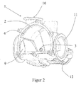
- FIG. 2 now shows a 3/2-way valve 1 that is used in the exhaust system.
- the inlet channel 9 is in this case connected to a particulate filter, not shown.
- Exhaust gas can flow via the first exhaust duct 10 via an exhaust gas cooler, not shown be returned to the internal combustion engine.
- the exhaust gas is passed to an exhaust pipe, not shown.
- the closure flap 2 can close the outlet channel 10 or 11 by an electromotive drive 12, which is connected to the closure flap via the rotation axis 3 and an arm 13.
- the invention is not limited to the described embodiment.
- the contact surface is formed on the concave side of the flap valve. In this case, only the direction of rotation would reverse at the valve opening.
Landscapes
- Engineering & Computer Science (AREA)
- General Engineering & Computer Science (AREA)
- Mechanical Engineering (AREA)
- Chemical & Material Sciences (AREA)
- Combustion & Propulsion (AREA)
- Lift Valve (AREA)
Abstract
Klappenventil, insbesondere für Brennkraftmaschinen, mit einem Gehäuse, dass mindestens eine Einlassöffnung und mindestens eine Auslassöffnung (6) aufweist, wobei eine Verschlussklappe (2) exzentrisch im Gehäuse gelagert ist, und derart um eine Drehachse (3) schwenkbar ist, dass die Verschlussklappe (2) mit deren Anlagefläche (4) mit mindestens einem Ventilsitz (5) zusammenwirkt, wobei die zum Ventilsitz (5) gerichtete Anlagefläche (4) in einer gekrümmten Ebene verläuft, in derart, dass bei einem von der Drehachse (3) abgewandten Ventilsitz (5) die in Öffnungsrichtung weisende Seite (7) der Anlagefläche (4) einen größeren Abstand zur Drehachse (3) aufweist, als die in Schließrichtung weisende Seite (8) der Anlagefläche (4) und das bei einem der Drehachse (3) zugewandten Ventilsitz (5) die in Öffnungsrichtung weisende Seite der Anlagefläche (4) einen geringen Abstand zur Drehachse (3) aufweist als die in Schließrichtung weisende Seite der Anlagefläche (4).
Description
- Die Erfindung betrifft ein Klappenventil, insbesondere für Brennkraftmaschinen, mit einem Gehäuse, dass mindestens eine Einlassöffnung und mindestens eine Auslassöffnung aufweist, wobei eine Verschlussklappe exzentrisch im Gehäuse gelagert ist und derart um eine Drehachse schwenkbar ist, dass die Verschlussklappe mit deren Anlagefläche mit mindestens einem Ventilsitz zusammenwirkt.
- Derartige Klappenventile sind hinlänglich bekannt. Sie werden als Drosselklappe, Abgasrückführventil, oder auch als Abgasklappe eingesetzt. Dabei zeigt beispielsweise die deutsche Druckschrift
DE 10053850 A1 verschiedene Ausführungsformen eines derartigen Ventils. Aufgrund der durch das Prinzip des Exzenter-Ventils ausgeführten Dreh- und Hubbewegung soll ein derartiges Klappenventil unempfindlicher gegen Verschmutzung oder auch Verschleiß aufgrund Reibung beim Ventilöffnungs- oder Schließvorgangs sein. Um ein derartiges Ventil auch gegenüber deutlich schwankenden Temperaturen funktionssicher zu gestalten, schlägt dieDE 10053850 A1 vor, die Ventilklappe über ein Gelenk mit dem Ventilgestänge zu verbinden, um so eine relative Bewegung zwischen Ventilklappe und Ventilsitz zu ermöglichen und auf diese Art und Weise einen selbstständigen Ausgleich von Abweichungen aufgrund von Fertigungsmängeln und/oder Wärmeausdehnungen aufzufangen. Jedoch ist auch diese Ausbildung einer Ventilklappe insbesondere beim Öffnungs- und Schließvorgang reibungsbedingt verschleißanfällig und ist das Problem der unterschiedlichen Wärmeausdehnung der einzelnen Teile durch die gelenkige Aufhängung der Ventilklappe immer noch nicht zufriedenstellend gelöst. - Daher liegt der Erfindung die Aufgabe zugrunde, die oben genannten Nachteile mit einem einfach aufgebauten Klappenventil zu vermeiden.
- Diese Aufgabe wird dadurch gelöst, dass die zum Ventilsitz gerichtete Anlagefläche in einer gekrümmten Ebene verläuft, derart, dass bei einem von der Drehachse abgewandten Ventilsitz die in Öffnungsrichtung weisende Seite der Ablagefläche einen größeren Abstand zur Drehachse aufweist, als die in Schließrichtung weisende Seite der Anlagefläche und das bei einem der Drehachse zugewandten Ventilsitz die in Öffnungsrichtung weisende Seite der Anlagefläche einen geringeren Abstand zur Drehachse aufweist, als die in Schließrichtung weisende Seite der Anlagefläche.
- Auf diese Weise wird ein Klappenventil geschaffen, dass auf besonders einfache Art und Weise herstellbar ist und bei dem insbesondere der Öffnungs- und Schließvorgang sicher und verschleißfrei erfolgt.
- Dadurch, dass bei einem derartigen Klappenventil eine Strecke senkrecht von einem Punkt P der Drehachse zur Anlagefläche der Verschlussklappe eine ebene Kurve mit ständig größer werdendem Abstand beschreibt, wird eine Anlagefläche geschaffen, die einfach, kostengünstig und reproduzierbar herzustellen ist, und den Anforderungen hinsichtlich möglich geringerer Haftreibung im Öffnungs- und Schließvorgang genügt.
- Dabei kann es insbesondere bei einem Einsatz mit hoher Wärmewirkung vorteilhaft sein, wenn die Kurve einen Abschnitt einer logarithmischen Spirale beschreibt. Auf diese Weise ist gewährleistet, dass jeder Punkt auf der Anlagefläche des Klappenventils beispielsweise beim Öffnen unter einem bestimmten Winkel vom Ventilsitz abhebt. Auf diese Art und Weise kann eine Stellvorrichtung, die das Klappenventil antreibt, besonders einfach auf die öffnungs- und Schließbedingungen abgestimmt werden. Des Weiteren ist gewährleistet, dass bei Wärmeeinwirkung auf das Klappenventil sich das Ventil selbstähnlich ausdehnt, dass heißt es bleibt Teil der selben logarithmischen Spirale. Dadurch passt sich die ausgedehnte Anlagefläche weiterhin dem Ventilsitz an, wobei sich lediglich im Schließwinkel ein geringer Winkelversatz einstellen kann.
- Des Weiteren kann es vorteilhaft sein, dass der Ventilsitz und/oder die Anlagefläche eine Kunststoffbeschichtung aufweisen, um eine hohe Abdichtwirkung zu erzielen.
- Ein Ausführungsbeispiel ist in den Zeichnungen dargestellt und wird nachfolgend beschrieben, dabei zeigt
-
Figur 1 : ein Klappenventil mit Ventilsitz in schematischer Form und -
Figur 2 : perspektivische Ansicht eines erfindungsgemäßen Klappenventils -
Figur 1 zeigt schematisch ein Klappenventil 1, mit einer Verschlussklappe 2, die exzentrisch um eine Drehachse 3 schwenkbar ist. Dabei weist die Verschlussklappe 2 eine Anlagefläche 4 auf, die im vorliegenden Fall mit einem Ventilsitz 5 zusammenwirkt. Die Verschlussklappe 2 verschließt im vorliegenden Ausführungsbeispiel eine Auslassöffnung 6. - Die zum Ventilsitz 5 gerichtete Anlagefläche 4 des Klappenventils 1 verläuft in einer gekrümmten Ebene, wobei die in Öffnungsrichtung weisende Seite 7 einen größeren Abstand zur Drehachse aufweist, als die in Schließrichtung weisende Seite 8 der Anlagefläche 4. Darüber hinaus beschreibt die Krümmung der Anlagefläche eine logarithmische Spirale, wodurch jeder Punkt auf der Dichtfläche der Anlagefläche beim Öffnen unter demselben Winkel von dem Ventilsitz 5 abhebt. Dehnt sich nun aufgrund von Wärmeeinwirkung die Verschlussklappe 2 aus, wachsen die Radien von der Drehachse 3 zur Anlagefläche 4 gemäß der Gesetzmäßigkeit R'=R (1+K(T-To)) T Temperatur, To Bezugstemperatur, k Wärmeausdehnungskoeffizient an. Die Form der Anlagefläche 4 der Verschlussklappe 2 ist dabei selbstähnlich, dass heißt sie bleibt Teil derselben logarithmischen Spirale. Dadurch passt die ausgedehnte Verschlussklappe 2 weiterhin zum Ventilsitz 5, wobei sich lediglich im Schließwinkel ein leichter Winkelversatz (siehe strichpunktierte Linie) einstellt.
-
Figur 2 zeigt nun ein 3/2 Wegeventil 1, dass im Abgasstrang eingesetzt wird. Der Einlasskanal 9 ist hierbei mit einem nicht dargestellten Partikelfilter verbunden. Über den ersten Auslasskanal 10 kann Abgas über einen nicht dargestellten Abgaskühler zur Brennkraftmaschine zurückgeführt werden. Über den zweiten Auslasskanal 11 wird das Abgas zu einem nicht dargestellten Auspuffrohr weitergeleitet. Die Verschlussklappe 2 kann je nach Ansteuerung durch einen elektromotorischen Antrieb 12, der über die Drehachse 3 und einen Arm 13 mit der Verschlussklappe verbunden ist, den Auslasskanal 10 oder 11 verschließen. - Es sollte deutlich sein, dass die Erfindung nicht auf das beschrieben Ausführungsbeispiel beschränkt ist. Insbesondere ist es auch möglich, dass die Anlagefläche auf der konkaven Seite des Klappenventils ausgebildet ist. Hierbei würde sich lediglich die Drehrichtung bei der Ventilöffnung umkehren.
Claims (4)
- Klappenventil, insbesondere für Brennkraftmaschinen, mit einem Gehäuse, dass mindestens eine Einlassöffnung und mindestens eine Auslassöffnung (6) aufweist, wobei eine Verschlussklappe (2) exzentrisch im Gehäuse gelagert ist, und derart um eine Drehachse (3) schwenkbar ist, dass die Verschlussklappe (2) mit deren Anlagefläche (4) mit mindestens einem Ventilsitz (5) zusammenwirkt,
dadurch gekennzeichnet, dass
die zum Ventilsitz (5) gerichtete Anlagefläche (4) in einer gekrümmten Ebene verläuft, in derart, dass bei einem von der Drehachse (3) abgewandten Ventilsitz (5) die in Öffnungsrichtung weisende Seite (7) der Anlagefläche (4) einen größeren Abstand zur Drehachse (3) aufweist, als die in Schließrichtung weisende Seite (8) der Anlagefläche (4) und das bei einem der Drehachse (3) zugewandten Ventilsitz (5) die in Öffnungsrichtung weisende Seite der Anlagefläche (4) einen geringen Abstand zur Drehachse (3) aufweist als die in Schließrichtung weisende Seite der Anlagefläche (4). - Klappenventil nach Anspruch 1, dadurch gekennzeichnet, dass eine Strecke senkrecht von einem Punkt P der Drehachse (3) zur Anlagefläche (4) der Verschlussklappe (2) eine ebene Kurve mit ständig größer werdenden Abstand beschreibt.
- Klappenventil nach Anspruch 2, dadurch gekennzeichnet, dass die Kurve einen Abschnitt einer logarithmischen Spirale beschreibt.
- Klappenventil nach einem der vorgehenden Ansprüche, dadurch gekennzeichnet, dass der Ventilsitz (5) und/oder die Anlagefläche (4) eine Kunststoffbeschichtung aufweisen.
Applications Claiming Priority (1)
| Application Number | Priority Date | Filing Date | Title |
|---|---|---|---|
| DE102009015183.4A DE102009015183B4 (de) | 2009-03-31 | 2009-03-31 | Klappenventil |
Publications (1)
| Publication Number | Publication Date |
|---|---|
| EP2236871A1 true EP2236871A1 (de) | 2010-10-06 |
Family
ID=42308559
Family Applications (1)
| Application Number | Title | Priority Date | Filing Date |
|---|---|---|---|
| EP10155117A Withdrawn EP2236871A1 (de) | 2009-03-31 | 2010-03-02 | Klappenventil |
Country Status (2)
| Country | Link |
|---|---|
| EP (1) | EP2236871A1 (de) |
| DE (1) | DE102009015183B4 (de) |
Cited By (3)
| Publication number | Priority date | Publication date | Assignee | Title |
|---|---|---|---|---|
| EP2653710A1 (de) * | 2012-04-17 | 2013-10-23 | Pierburg GmbH | Ventilvorrichtung für eine Verbrennungskraftmaschine |
| EP2752569A1 (de) * | 2013-01-04 | 2014-07-09 | Caterpillar Motoren GmbH & Co. KG | Drosselventil für Verbrennungsmotoren |
| CN109404546A (zh) * | 2018-12-16 | 2019-03-01 | 中国航发沈阳发动机研究所 | 一种发动机模式选择机构中的密封结构及设计方法 |
Citations (4)
| Publication number | Priority date | Publication date | Assignee | Title |
|---|---|---|---|---|
| US3807690A (en) * | 1972-07-22 | 1974-04-30 | Bopp & Reuther Gmbh | Valve construction |
| US4436281A (en) * | 1979-05-23 | 1984-03-13 | Applications Mecaniques Et Robinetterie Industrielle | Butterfly valve with an improved obturation device |
| GB2199641A (en) * | 1987-01-02 | 1988-07-13 | Somas Ventiler | Butterfly valve |
| DE10053850A1 (de) | 2000-10-30 | 2002-05-08 | Bosch Gmbh Robert | Exzenterventil |
Family Cites Families (5)
| Publication number | Priority date | Publication date | Assignee | Title |
|---|---|---|---|---|
| GB870804A (en) * | 1958-08-20 | 1961-06-21 | Gwynnes Pumps Ltd | Improvements relating to valves for the control of fluids |
| DE2344911C3 (de) * | 1973-09-06 | 1978-10-12 | Eckardt Ag, 7000 Stuttgart | Ventil |
| DE3218210A1 (de) * | 1982-05-14 | 1983-11-17 | Robert Bosch Gmbh, 7000 Stuttgart | Vorrichtung zur steuerung mindestens eines drosselquerschnittes in einer steuerleitung |
| US4640492A (en) * | 1985-01-23 | 1987-02-03 | General Signal Corporation | Involute valve closure |
| FR2893363A1 (fr) * | 2005-11-11 | 2007-05-18 | Denso Corp | Vanne et dispositif de recyclage de gaz d'echappement pour un moteur |
-
2009
- 2009-03-31 DE DE102009015183.4A patent/DE102009015183B4/de not_active Expired - Fee Related
-
2010
- 2010-03-02 EP EP10155117A patent/EP2236871A1/de not_active Withdrawn
Patent Citations (4)
| Publication number | Priority date | Publication date | Assignee | Title |
|---|---|---|---|---|
| US3807690A (en) * | 1972-07-22 | 1974-04-30 | Bopp & Reuther Gmbh | Valve construction |
| US4436281A (en) * | 1979-05-23 | 1984-03-13 | Applications Mecaniques Et Robinetterie Industrielle | Butterfly valve with an improved obturation device |
| GB2199641A (en) * | 1987-01-02 | 1988-07-13 | Somas Ventiler | Butterfly valve |
| DE10053850A1 (de) | 2000-10-30 | 2002-05-08 | Bosch Gmbh Robert | Exzenterventil |
Cited By (3)
| Publication number | Priority date | Publication date | Assignee | Title |
|---|---|---|---|---|
| EP2653710A1 (de) * | 2012-04-17 | 2013-10-23 | Pierburg GmbH | Ventilvorrichtung für eine Verbrennungskraftmaschine |
| EP2752569A1 (de) * | 2013-01-04 | 2014-07-09 | Caterpillar Motoren GmbH & Co. KG | Drosselventil für Verbrennungsmotoren |
| CN109404546A (zh) * | 2018-12-16 | 2019-03-01 | 中国航发沈阳发动机研究所 | 一种发动机模式选择机构中的密封结构及设计方法 |
Also Published As
| Publication number | Publication date |
|---|---|
| DE102009015183B4 (de) | 2014-04-17 |
| DE102009015183A1 (de) | 2010-10-07 |
Similar Documents
| Publication | Publication Date | Title |
|---|---|---|
| DE69704322T2 (de) | Vorrichtung zur Abgasrückführung | |
| DE19500475C2 (de) | Absperr- oder Drosselventil mit drehbarer Ventilklappe | |
| DE102012219822A1 (de) | Niederdruck-Abgasrückführungs-System | |
| DE112004000677B4 (de) | Auspuff für einen Verbrennungsmotor und Dreiwegeventil für einen solchen Auspuff | |
| DE102011106744B3 (de) | Ventilvorrichtung zur Regelung eines Abgasstroms einer Verbrennungskraftmaschine | |
| EP2791487B1 (de) | Betätigungseinrichtung für eine turbine eines abgasturboladers | |
| EP2212539B1 (de) | Ventileinrichtung für eine abgasrückführungseinrichtung | |
| DE102014200698A1 (de) | Niederdruck-EGR-Ventil | |
| EP2803838B1 (de) | Abgasturbolader-Anordnung | |
| DE102009015183B4 (de) | Klappenventil | |
| EP2395216B1 (de) | Klappenvorrichtung für eine Verbrennungskraftmaschine | |
| DE102017222465A1 (de) | Klappeneinrichtung für den Abgasstrang eines Verbrennungsmotors | |
| DE102009015184B4 (de) | Klappenventil | |
| DE102004058719A1 (de) | Abgasturbolader mit variabler Turbinengeometrie | |
| DE102007055422A1 (de) | Ventil zur Steuerung des Durchflusses eines gasförmigen oder flüssigen Mediums | |
| WO2019030120A1 (de) | Ventileinrichtung für eine turbine eines abgasturboladers, sowie turbine für einen abgasturbolader | |
| WO2018197262A1 (de) | Regelvorrichtung für eine verbrennungskraftmaschine | |
| EP3548721B1 (de) | Brennkraftmaschine mit einem zylinderkopf sowie mit einem sekundärluftsystem | |
| DE10101412A1 (de) | Abgasrückführeinrichtung für eine Brennkraftmaschine | |
| EP1927746A1 (de) | Abgassteuereinrichtung für eine Verbrennungskraftmaschine | |
| EP3452716B1 (de) | Regelvorrichtung | |
| DE112019004699T5 (de) | Wastegateanordnung | |
| WO2006136213A1 (de) | Ventil, insbesondere für eine kraftfahrzeug-abgasanlage | |
| DE102016112403B4 (de) | Regelvorrichtung für eine Verbrennungskraftmaschine und Verfahren zum Betreiben einer solchen | |
| DE19837097A1 (de) | Abgasanlage einer Brennkraftmaschine |
Legal Events
| Date | Code | Title | Description |
|---|---|---|---|
| PUAI | Public reference made under article 153(3) epc to a published international application that has entered the european phase |
Free format text: ORIGINAL CODE: 0009012 |
|
| AK | Designated contracting states |
Kind code of ref document: A1 Designated state(s): AT BE BG CH CY CZ DE DK EE ES FI FR GB GR HR HU IE IS IT LI LT LU LV MC MK MT NL NO PL PT RO SE SI SK SM TR |
|
| AX | Request for extension of the european patent |
Extension state: AL BA ME RS |
|
| 17P | Request for examination filed |
Effective date: 20101201 |
|
| 18D | Application deemed to be withdrawn |
Effective date: 20110729 |
|
| STAA | Information on the status of an ep patent application or granted ep patent |
Free format text: STATUS: THE APPLICATION IS DEEMED TO BE WITHDRAWN |
|
| R18D | Application deemed to be withdrawn (corrected) |
Effective date: 20110407 |