EP2236867A1 - Sealing Device - Google Patents
Sealing Device Download PDFInfo
- Publication number
- EP2236867A1 EP2236867A1 EP10003241A EP10003241A EP2236867A1 EP 2236867 A1 EP2236867 A1 EP 2236867A1 EP 10003241 A EP10003241 A EP 10003241A EP 10003241 A EP10003241 A EP 10003241A EP 2236867 A1 EP2236867 A1 EP 2236867A1
- Authority
- EP
- European Patent Office
- Prior art keywords
- valve stem
- peripheral surface
- sealing
- seal
- rubber
- Prior art date
- Legal status (The legal status is an assumption and is not a legal conclusion. Google has not performed a legal analysis and makes no representation as to the accuracy of the status listed.)
- Withdrawn
Links
- 238000007789 sealing Methods 0.000 title claims abstract description 36
- 230000002093 peripheral effect Effects 0.000 claims abstract description 33
- 229920001971 elastomer Polymers 0.000 claims abstract description 24
- 230000000717 retained effect Effects 0.000 claims abstract description 5
- 238000000926 separation method Methods 0.000 abstract description 5
- 238000000465 moulding Methods 0.000 description 3
- 238000004073 vulcanization Methods 0.000 description 3
- 238000010586 diagram Methods 0.000 description 2
- 239000013013 elastic material Substances 0.000 description 2
- YCKRFDGAMUMZLT-UHFFFAOYSA-N Fluorine atom Chemical compound [F] YCKRFDGAMUMZLT-UHFFFAOYSA-N 0.000 description 1
- 229910000831 Steel Inorganic materials 0.000 description 1
- 230000007547 defect Effects 0.000 description 1
- 230000000694 effects Effects 0.000 description 1
- 229910052731 fluorine Inorganic materials 0.000 description 1
- 239000011737 fluorine Substances 0.000 description 1
- 238000004519 manufacturing process Methods 0.000 description 1
- 238000000034 method Methods 0.000 description 1
- 229920002379 silicone rubber Polymers 0.000 description 1
- 239000004945 silicone rubber Substances 0.000 description 1
- 239000010959 steel Substances 0.000 description 1
Images



Classifications
-
- F—MECHANICAL ENGINEERING; LIGHTING; HEATING; WEAPONS; BLASTING
- F16—ENGINEERING ELEMENTS AND UNITS; GENERAL MEASURES FOR PRODUCING AND MAINTAINING EFFECTIVE FUNCTIONING OF MACHINES OR INSTALLATIONS; THERMAL INSULATION IN GENERAL
- F16J—PISTONS; CYLINDERS; SEALINGS
- F16J15/00—Sealings
- F16J15/16—Sealings between relatively-moving surfaces
- F16J15/32—Sealings between relatively-moving surfaces with elastic sealings, e.g. O-rings
- F16J15/3268—Mounting of sealing rings
- F16J15/3276—Mounting of sealing rings with additional static sealing between the sealing, or its casing or support, and the surface on which it is mounted
-
- F—MECHANICAL ENGINEERING; LIGHTING; HEATING; WEAPONS; BLASTING
- F01—MACHINES OR ENGINES IN GENERAL; ENGINE PLANTS IN GENERAL; STEAM ENGINES
- F01L—CYCLICALLY OPERATING VALVES FOR MACHINES OR ENGINES
- F01L3/00—Lift-valve, i.e. cut-off apparatus with closure members having at least a component of their opening and closing motion perpendicular to the closing faces; Parts or accessories thereof
- F01L3/08—Valves guides; Sealing of valve stem, e.g. sealing by lubricant
-
- F—MECHANICAL ENGINEERING; LIGHTING; HEATING; WEAPONS; BLASTING
- F16—ENGINEERING ELEMENTS AND UNITS; GENERAL MEASURES FOR PRODUCING AND MAINTAINING EFFECTIVE FUNCTIONING OF MACHINES OR INSTALLATIONS; THERMAL INSULATION IN GENERAL
- F16J—PISTONS; CYLINDERS; SEALINGS
- F16J15/00—Sealings
- F16J15/16—Sealings between relatively-moving surfaces
- F16J15/32—Sealings between relatively-moving surfaces with elastic sealings, e.g. O-rings
- F16J15/3248—Sealings between relatively-moving surfaces with elastic sealings, e.g. O-rings provided with casings or supports
- F16J15/3252—Sealings between relatively-moving surfaces with elastic sealings, e.g. O-rings provided with casings or supports with rigid casings or supports
Definitions
- the present invention relates to a sealing device, and more specificity to a sealing device used for a valve stem.
- a valve stem seal has been known as a kind of a lip seal with a metallic ring, and the valve stem seal is broadly classified into a valve stem seal provided integrally with a spring retaining portion and a valve stem seal provided separately from a spring retaining portion.
- Patent Document 1 Patent Document 1
- a seal lip 20 is integrally fixed to one end of a metallic ring 10 by baking, and a spring retaining portion 30 for receiving a spring (valve spring) 40 is provided in another end of the metallic ring 10.
- a valve stem seal 70 provided separately from a spring retaining portion is configured such that the metallic ring 10 of the seal lip 20 is provided separately from a spring retaining portion (not shown) for receiving a valve spring, in this case, the spring retaining portion is directly attached to a cylinder head.
- valve stem seal provided integrally with the spring retaining portion, there is a defect that although the overall number of components can be reduced, since there is a need to provide a curing process for the spring retaining portion 30 of the metallic ring 10, a lot of effort and time is required for the manufacturing of the metallic ring 10, and because the seal ring 20 has to be baked to the large metallic ring 10, the molding cost may increase, thereby increasing the costs.
- valve stem seal 70 provided separately from the spring retaining portion, there is a risk that since the valve stem seal 70 is retained on an outer peripheral surface of a valve stem guide 5 by a rubber fitting portion 60, when a port pressure becomes high, a valve stem seal 70 may become separated from the valve stem guide 5.
- the rubber fitting portion 60 is formed in a lip shape and has a configuration with an improved sealing function, it is difficult to obtain a sufficient fitting force.
- the present invention has been made in view of the above circumstances and an object thereof is to provide a sealing device which is capable of maintaining a satisfactory sealing performance between a valve stem seal and a valve stem guide without separation of the valve stem seal even under a high port pressure, the valve stem seal being provided separately from a spring retaining portion.
- the present invention provides a sealing device in which a spring retaining portion of a valve spring is provided separately from a valve stem seal, the valve stem seal including a cylindrical metallic ring, a rubber-elastic seal lip that seals a valve stem provided in one end of the metallic ring while sliding on the valve stem, and a sealing-fitting means that seals an outer peripheral surface of a valve stem guide provided in the inner peripheral side of the metallic ring while being fitted to the outer peripheral surface, wherein the sealing-fitting means includes a metallic fitting portion in which the metallic ring directly contacts the outer peripheral surface of the valve stem guide, and a rubber-elastic rubber fitting portion which is integrally retained in an inner peripheral surface of the metallic ring so as to contact the outer peripheral surface of the valve stem guide.
- the present invention exhibits the effects as described hereinafter.
- a satisfactory sealing performance can be maintained between the valve stem seal and the valve stem guide without separation of the valve stem seal even under a high port pressure.
- the rubber fitting portion can prevent oil from permeating into the metallic fitting portion, a strong fitting force of the metallic fitting portion can be maintained.
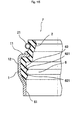
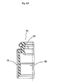
- Fig. 1 is a side view of a sealing device according to the present invention.
- Fig. 2 is a diagram in which the sealing device in Fig. 1 is mounted to a valve stem guide.
- a valve stem seal 7 constituting a sealing device includes a cylindrical metallic ring 1, a rubber-elastic seal lip 2 that seals a valve stem provided in one end of the metallic ring 1 while sliding on the valve stem 1, and a sealing-fitting means 6 that seals an outer peripheral surface of a valve stem guide 5 and is provided in the inner peripheral side of the metallic ring 1 while being fitted to the outer peripheral surface.
- the sealing-fitting means 6 includes a metallic fitting portion 61 in which the metallic ring 1 directly contacts the outer peripheral surface of the valve stem guide 5, and a rubber-elastic rubber fitting portion 62 which is integrally retained in the inner peripheral surface of the metallic ring 1 so as to contact the outer peripheral surface of the valve stem guide 5.
- the sealing device according to the present invention is a valve stem seal provided separately from the spring retainer in which the spring retaining portion of the valve spring is provided separately from the valve stem seal 7.
- the metallic ring 1 has the cylindrical metallic fitting portion 61 at one end thereof, a flange portion 11 at another end thereof, and an enlarged-diameter cylinder portion 12.
- the cylindrical metallic fitting portion 61 is directly fitted into the outer peripheral surface of the valve stem guide 5, the flange portion 11 is formed integrally by the vulcanization bonding of the seal lip 2, and the enlarged-diameter cylinder portion 12 connects the flange portion 11 with the metallic fitting portion 61.
- the cylindrical metallic ring 1 is produced by press molding or the like from a plate-shaped steel plate.
- the seal lip 2 a valve stem seal and is slidably close to an outer peripheral surface of (not shown).
- a coil spring 21 is disposed on the outer peripheral surface of the seal lip 2.
- the rubber fitting portion 62 which is simultaneously formed of the same rubber elastic material as the seal lip 2, is bonded by vulcanization.
- an outer diameter of the valve stem guide 5 into which the metallic fitting portion 61 is fitted is larger than an outer diameter of the valve stem guide 5 with which the rubber fitting portion 62 comes in sealing contact, whereby a step 51 exists therebetween.
- a fluorine rubber, an NBR, a silicone rubber or the like may be suitably selected and used.
- the lip-shaped portions 621 and 621 of the rubber fitting portion 62 can reliably prevent the passage of the oil, and the fitting force of the metallic fitting portion 61 with the outer peripheral surface of the valve stem guide 5 can prevent the separation of the valve stem seal 7 from the valve stem guide 5,
- the rubber fitting portion 62 and the seal lip 2 have been formed integrally with the metallic ring 1 by vulcanization bonding, the rubber fitting portion 62 may be bonded and fixed to the inner peripheral surface of the metallic ring 1 after being formed separately.
- the present invention is not limited to the above-mentioned preferred embodiment for carrying out the invention, but can adopt various other structures without departing from the gist of the present invention.
Landscapes
- Engineering & Computer Science (AREA)
- General Engineering & Computer Science (AREA)
- Mechanical Engineering (AREA)
- Sealing With Elastic Sealing Lips (AREA)
Abstract
An object of the present invention is to provide a sealing device capable of maintaining a satisfactory sealing performance between a valve stem seal and a valve stem guide without separation of the valve stem seal even under a high port pressure, the valve stem seal being provided separately from a spring retaining portion.
There is provided a sealing device in which a spring retaining portion (30) of a valve spring (40) is provided separately from a valve stem seal (7), the valve stem seal including a cylindrical metallic ring (1), a rubber-elastic seal lip (2) sealing a valve stem and provided in one end of the metallic ring while sliding on the valve stem, and sealing-fitting means (6) sealing an outer peripheral surface of a valve stem guide (5) provided in the inner peripheral side of the metallic ring while being fitted to the outer peripheral surface, wherein the sealing-fitting means includes a metallic fitting portion (61) in which the metallic ring directly contacts the outer peripheral surface of the valve stem guide, and a rubber-elastic rubber fitting portion (62) which is integrally retained in the inner peripheral surface of the metallic ring so as to contact the outer peripheral surface of the valve stem guide.
Description
- The present invention relates to a sealing device, and more specificity to a sealing device used for a valve stem.
- Hitherto, a valve stem seal has been known as a kind of a lip seal with a metallic ring, and the valve stem seal is broadly classified into a valve stem seal provided integrally with a spring retaining portion and a valve stem seal provided separately from a spring retaining portion. (Patent Document 1)
- As shown in
Fig. 5 , in avalve stem seal 70 provided integrally with a spring retaining portion, aseal lip 20 is integrally fixed to one end of ametallic ring 10 by baking, and aspring retaining portion 30 for receiving a spring (valve spring) 40 is provided in another end of themetallic ring 10. - On the other hand, as shown in
Fig. 4 , since avalve stem seal 70 provided separately from a spring retaining portion is configured such that themetallic ring 10 of theseal lip 20 is provided separately from a spring retaining portion (not shown) for receiving a valve spring, in this case, the spring retaining portion is directly attached to a cylinder head. - However, according to the former valve stem seal provided integrally with the spring retaining portion, there is a defect that although the overall number of components can be reduced, since there is a need to provide a curing process for the
spring retaining portion 30 of themetallic ring 10, a lot of effort and time is required for the manufacturing of themetallic ring 10, and because theseal ring 20 has to be baked to the largemetallic ring 10, the molding cost may increase, thereby increasing the costs. - In addition, according to the latter valve stem seal provided separately from the spring retaining portion, there is a risk that since the
valve stem seal 70 is retained on an outer peripheral surface of avalve stem guide 5 by arubber fitting portion 60, when a port pressure becomes high, avalve stem seal 70 may become separated from thevalve stem guide 5. - As a result, when the fitting force of the
rubber fitting portion 60 is increased so as to reduce the risk that thevalve stem seal 70 is separated from thevalve stem guide 5, there is a problem in that the rubber is permanently deformed. - In particular, in a case where the
rubber fitting portion 60 is formed in a lip shape and has a configuration with an improved sealing function, it is difficult to obtain a sufficient fitting force. - Thus, a metallic fitting type
valve stem seal 70 as shown inFig. 3 has been proposed which does not have the risk of the separation even under a high port pressure, - However, when the metallic fitting type
valve stem seal 70 is attached to the outer peripheral surface of thevalve stem guide 5, a large force is required, and the seal property of themetallic fitting surface 60 is insufficient. - [Patent Document 1] Japanese Patent Application Laid-Open No.
2003-343734 - [Patent Document 2] Japanese Patent Application Laid-Open No.
2004-011867 - The present invention has been made in view of the above circumstances and an object thereof is to provide a sealing device which is capable of maintaining a satisfactory sealing performance between a valve stem seal and a valve stem guide without separation of the valve stem seal even under a high port pressure, the valve stem seal being provided separately from a spring retaining portion.
- The present invention provides a sealing device in which a spring retaining portion of a valve spring is provided separately from a valve stem seal, the valve stem seal including a cylindrical metallic ring, a rubber-elastic seal lip that seals a valve stem provided in one end of the metallic ring while sliding on the valve stem, and a sealing-fitting means that seals an outer peripheral surface of a valve stem guide provided in the inner peripheral side of the metallic ring while being fitted to the outer peripheral surface, wherein the sealing-fitting means includes a metallic fitting portion in which the metallic ring directly contacts the outer peripheral surface of the valve stem guide, and a rubber-elastic rubber fitting portion which is integrally retained in an inner peripheral surface of the metallic ring so as to contact the outer peripheral surface of the valve stem guide.
- The present invention exhibits the effects as described hereinafter.
- According to a sealing device of the invention described in Claim 1, in a valve stem seal provided separately from a spring retaining portion, a satisfactory sealing performance can be maintained between the valve stem seal and the valve stem guide without separation of the valve stem seal even under a high port pressure.
- Furthermore, according to the sealing device of the invention described in
Claim 2, because the rubber fitting portion can prevent oil from permeating into the metallic fitting portion, a strong fitting force of the metallic fitting portion can be maintained. - In addition, according to the sealing device of the invention described in Claim 3, it is possible to suppress the molding cost to be a low level.
- Furthermore, according to the sealing device of the invention described in Claim 4, since an excessive fitting force is not required for the rubber fitting portion, a satisfactory seal performance by the lip can be maintained.
- In addition, according to the sealing device of the invention described in
Claim 5, a more satisfactory seal performance can be maintained. -
- Fig. 1
- is a side view of a sealing device according to the present invention.
- Fig. 2
- is a diagram showing a state in which the sealing device of
Fig. 1 is mounted to a valve stem guide. - Fig. 3
- is a sectional view of a sealing device provided separately from a spring retainer according to a related art.
- Fig. 4
- is a sectional view of another sealing device provided separately from a spring retainer according to a related art.
- Fig. 5
- is a sectional view of a sealing device provided integrally with a spring retainer according to a related art.
- Hereinafter, the most preferred embodiment for carrying out the present invention will be described.
- The most preferred embodiment for carrying out the present invention will be described based on
Figs. 1 and2 . -
Fig. 1 is a side view of a sealing device according to the present invention. -
Fig. 2 is a diagram in which the sealing device inFig. 1 is mounted to a valve stem guide. - In
Fig. 1 , avalve stem seal 7 constituting a sealing device according to the present invention includes a cylindrical metallic ring 1, a rubber-elastic seal lip 2 that seals a valve stem provided in one end of the metallic ring 1 while sliding on the valve stem 1, and a sealing-fitting means 6 that seals an outer peripheral surface of avalve stem guide 5 and is provided in the inner peripheral side of the metallic ring 1 while being fitted to the outer peripheral surface. - Furthermore, the sealing-fitting means 6 includes a
metallic fitting portion 61 in which the metallic ring 1 directly contacts the outer peripheral surface of thevalve stem guide 5, and a rubber-elasticrubber fitting portion 62 which is integrally retained in the inner peripheral surface of the metallic ring 1 so as to contact the outer peripheral surface of thevalve stem guide 5. - Furthermore, the sealing device according to the present invention is a valve stem seal provided separately from the spring retainer in which the spring retaining portion of the valve spring is provided separately from the
valve stem seal 7. - In addition, the metallic ring 1 has the cylindrical
metallic fitting portion 61 at one end thereof, aflange portion 11 at another end thereof, and an enlarged-diameter cylinder portion 12. The cylindricalmetallic fitting portion 61 is directly fitted into the outer peripheral surface of thevalve stem guide 5, theflange portion 11 is formed integrally by the vulcanization bonding of theseal lip 2, and the enlarged-diameter cylinder portion 12 connects theflange portion 11 with themetallic fitting portion 61. - In general, the cylindrical metallic ring 1 is produced by press molding or the like from a plate-shaped steel plate.
- The seal lip 2 a valve stem seal and is slidably close to an outer peripheral surface of (not shown).
- Furthermore, in order to adjust the closing force of the
seal lip 2 to the valve, acoil spring 21 is disposed on the outer peripheral surface of theseal lip 2. - In addition, on the inner peripheral surface of the enlarged-
diameter cylinder portion 12, therubber fitting portion 62, which is simultaneously formed of the same rubber elastic material as theseal lip 2, is bonded by vulcanization. - On the
rubber fitting portion 62, two lip-shaped portions metallic fitting portion 61 to the inner side. - Furthermore, as shown in
Fig. 2 , an outer diameter of thevalve stem guide 5 into which themetallic fitting portion 61 is fitted is larger than an outer diameter of thevalve stem guide 5 with which therubber fitting portion 62 comes in sealing contact, whereby astep 51 exists therebetween. - For this reason, because of the existence of a
step 51, damage to therubber fitting portion 62 can be effectively prevented. - As the rubber elastic material, a fluorine rubber, an NBR, a silicone rubber or the like may be suitably selected and used.
- In this manner, the lip-
shaped portions rubber fitting portion 62 can reliably prevent the passage of the oil, and the fitting force of themetallic fitting portion 61 with the outer peripheral surface of thevalve stem guide 5 can prevent the separation of thevalve stem seal 7 from thevalve stem guide 5, - As a result, since the
rubber fitting portion 62 does not need an excessive fitting force, the lip-shaped portions shaped portions - In addition, although in the present embodiment, the
rubber fitting portion 62 and theseal lip 2 have been formed integrally with the metallic ring 1 by vulcanization bonding, therubber fitting portion 62 may be bonded and fixed to the inner peripheral surface of the metallic ring 1 after being formed separately. - Furthermore, it is needless to say that the present invention is not limited to the above-mentioned preferred embodiment for carrying out the invention, but can adopt various other structures without departing from the gist of the present invention.
Claims (5)
- A sealing device in which a spring retaining portion (30) of a valve spring (40) is provided separately from a valve stem seal (7), the valve stem seal (7) including a cylindrical metallic ring (1), a rubber-elastic seal lip (2) sealing a valve stem provided in one end of the metallic ring (1) while sliding on the valve stem, and a sealing-fitting means (6) sealing an outer peripheral surface of a valve stem guide (5) and being provided in an inner peripheral side of the metallic ring (1) while being fitted to the outer peripheral surface, wherein the sealing-fitting means (6) includes a metallic fitting portion (61) in which the metallic ring (1) directly contacts the outer peripheral surface of the valve stem guide (5), and a rubber-elastic rubber fitting portion (62) which is integrally retained in the inner peripheral surface of the metallic ring (1) so as to contact the outer peripheral surface of the valve stem guide (5).
- The sealing device as claimed in claim 1, wherein the rubber fitting portion (62) is disposed closer to the seal lip (2) than the metallic fitting portion (61).
- The sealing device as claimed in claim 2, wherein the rubber fitting portion (62) is formed at the same time as the seal lip (2) is formed.
- The sealing device as claimed in any one of claims 1 to 3, wherein the rubber fitting portion (62) is formed with a lip-shaped portion (621).
- The sealing device as claimed in claim 4, wherein the number of the lip-shaped portions (621) is two.
Applications Claiming Priority (1)
| Application Number | Priority Date | Filing Date | Title |
|---|---|---|---|
| JP2009090726A JP2010242823A (en) | 2009-04-03 | 2009-04-03 | Sealing device |
Publications (1)
| Publication Number | Publication Date |
|---|---|
| EP2236867A1 true EP2236867A1 (en) | 2010-10-06 |
Family
ID=42236588
Family Applications (1)
| Application Number | Title | Priority Date | Filing Date |
|---|---|---|---|
| EP10003241A Withdrawn EP2236867A1 (en) | 2009-04-03 | 2010-03-26 | Sealing Device |
Country Status (2)
| Country | Link |
|---|---|
| EP (1) | EP2236867A1 (en) |
| JP (1) | JP2010242823A (en) |
Cited By (5)
| Publication number | Priority date | Publication date | Assignee | Title |
|---|---|---|---|---|
| CN103244684A (en) * | 2012-02-08 | 2013-08-14 | 德纳汽车系统集团有限责任公司 | Hybrid valve stem seal retainer assembly |
| US9371749B2 (en) | 2012-02-08 | 2016-06-21 | Dana Automotive Systems Group, Llc | Hybrid valve stem seal retainer assembly |
| DE102015209427A1 (en) * | 2015-05-22 | 2016-11-24 | Aktiebolaget Skf | Seal for sealing a valve stem, tool and method for mounting a seal on a guide member of a valve stem |
| CN114746678A (en) * | 2020-04-28 | 2022-07-12 | Nok株式会社 | Valve stem seal |
| DE102021102911A1 (en) | 2021-02-09 | 2022-08-11 | Audi Aktiengesellschaft | Valve stem seal for an internal combustion engine and corresponding internal combustion engine |
Citations (5)
| Publication number | Priority date | Publication date | Assignee | Title |
|---|---|---|---|---|
| EP0898057A2 (en) * | 1997-08-21 | 1999-02-24 | CR Elastomere GmbH | Valve stem seal |
| JP2003343734A (en) | 2002-05-24 | 2003-12-03 | Nok Corp | Sealing device |
| JP2004011867A (en) | 2002-06-11 | 2004-01-15 | Nok Corp | Sealing device |
| JP2004019852A (en) * | 2002-06-19 | 2004-01-22 | Nok Corp | Valve stem seal |
| US20050001196A1 (en) * | 2003-07-02 | 2005-01-06 | Dana Corporation | Valve stem seal assembly |
-
2009
- 2009-04-03 JP JP2009090726A patent/JP2010242823A/en not_active Withdrawn
-
2010
- 2010-03-26 EP EP10003241A patent/EP2236867A1/en not_active Withdrawn
Patent Citations (5)
| Publication number | Priority date | Publication date | Assignee | Title |
|---|---|---|---|---|
| EP0898057A2 (en) * | 1997-08-21 | 1999-02-24 | CR Elastomere GmbH | Valve stem seal |
| JP2003343734A (en) | 2002-05-24 | 2003-12-03 | Nok Corp | Sealing device |
| JP2004011867A (en) | 2002-06-11 | 2004-01-15 | Nok Corp | Sealing device |
| JP2004019852A (en) * | 2002-06-19 | 2004-01-22 | Nok Corp | Valve stem seal |
| US20050001196A1 (en) * | 2003-07-02 | 2005-01-06 | Dana Corporation | Valve stem seal assembly |
Cited By (9)
| Publication number | Priority date | Publication date | Assignee | Title |
|---|---|---|---|---|
| CN103244684A (en) * | 2012-02-08 | 2013-08-14 | 德纳汽车系统集团有限责任公司 | Hybrid valve stem seal retainer assembly |
| EP2626524A1 (en) * | 2012-02-08 | 2013-08-14 | Dana Automotive Systems Group , LLC | Hybrid valve stem seal retainer assembly |
| US9371749B2 (en) | 2012-02-08 | 2016-06-21 | Dana Automotive Systems Group, Llc | Hybrid valve stem seal retainer assembly |
| CN103244684B (en) * | 2012-02-08 | 2017-08-11 | 德纳汽车系统集团有限责任公司 | Hybrid valve stem seal retainer component |
| DE102015209427A1 (en) * | 2015-05-22 | 2016-11-24 | Aktiebolaget Skf | Seal for sealing a valve stem, tool and method for mounting a seal on a guide member of a valve stem |
| US10443734B2 (en) | 2015-05-22 | 2019-10-15 | Aktiebolaget Skf | Seal for sealing a valve shaft, tool and method for mounting a seal to a guide element of a valve shaft |
| CN114746678A (en) * | 2020-04-28 | 2022-07-12 | Nok株式会社 | Valve stem seal |
| DE102021102911A1 (en) | 2021-02-09 | 2022-08-11 | Audi Aktiengesellschaft | Valve stem seal for an internal combustion engine and corresponding internal combustion engine |
| DE102021102911B4 (en) | 2021-02-09 | 2024-12-19 | Audi Aktiengesellschaft | Valve stem seal for an internal combustion engine and corresponding internal combustion engine |
Also Published As
| Publication number | Publication date |
|---|---|
| JP2010242823A (en) | 2010-10-28 |
Similar Documents
| Publication | Publication Date | Title |
|---|---|---|
| US10197162B2 (en) | Gasket | |
| US10612660B2 (en) | Gasket | |
| CN110537042B (en) | Positive and negative pressure gasket | |
| CN101446352B (en) | Lip type seal | |
| EP1854965A1 (en) | Oil seal | |
| US20190331248A1 (en) | Valve | |
| US9221225B2 (en) | Sealing bellows, method for the production thereof and sealing bellows arrangement | |
| KR101723367B1 (en) | Sealing device | |
| CN106168144A (en) | For the sealing device of sealed valve stem, and for the tool and method installed | |
| CN109073086B (en) | Dust-proof sealing part | |
| CN106402386A (en) | Seal for pressurized fluid and open interface gap | |
| JP2010242823A (en) | Sealing device | |
| JP6527738B2 (en) | duct | |
| EP2110521A1 (en) | Sealing device | |
| US11242796B2 (en) | Valve | |
| JP2017227243A (en) | Fixing structure of sealing device | |
| JP2006258163A (en) | Sealing device | |
| EP2730757A1 (en) | Valve stem seal device | |
| CN112805492A (en) | Sealing element | |
| KR20150091993A (en) | Oil seal | |
| JP2016194343A (en) | Valve stem seal | |
| JP6442213B2 (en) | Sealing device | |
| CN222163551U (en) | Sealing structure and workpiece | |
| JP2007024205A (en) | Oil seal | |
| JP5453975B2 (en) | Rubber baked parts assembly |
Legal Events
| Date | Code | Title | Description |
|---|---|---|---|
| PUAI | Public reference made under article 153(3) epc to a published international application that has entered the european phase |
Free format text: ORIGINAL CODE: 0009012 |
|
| AK | Designated contracting states |
Kind code of ref document: A1 Designated state(s): AT BE BG CH CY CZ DE DK EE ES FI FR GB GR HR HU IE IS IT LI LT LU LV MC MK MT NL NO PL PT RO SE SI SK SM TR |
|
| AX | Request for extension of the european patent |
Extension state: AL BA ME RS |
|
| STAA | Information on the status of an ep patent application or granted ep patent |
Free format text: STATUS: THE APPLICATION IS DEEMED TO BE WITHDRAWN |
|
| 18D | Application deemed to be withdrawn |
Effective date: 20110407 |