EP2236820A2 - Voltage control method and system for a power generation plant and wind farm. - Google Patents
Voltage control method and system for a power generation plant and wind farm. Download PDFInfo
- Publication number
- EP2236820A2 EP2236820A2 EP10156701A EP10156701A EP2236820A2 EP 2236820 A2 EP2236820 A2 EP 2236820A2 EP 10156701 A EP10156701 A EP 10156701A EP 10156701 A EP10156701 A EP 10156701A EP 2236820 A2 EP2236820 A2 EP 2236820A2
- Authority
- EP
- European Patent Office
- Prior art keywords
- grid
- voltage
- sub
- generation plant
- power generation
- Prior art date
- Legal status (The legal status is an assumption and is not a legal conclusion. Google has not performed a legal analysis and makes no representation as to the accuracy of the status listed.)
- Granted
Links
- 238000010248 power generation Methods 0.000 title claims abstract description 54
- 238000000034 method Methods 0.000 title claims abstract description 36
- 238000004364 calculation method Methods 0.000 description 25
- 238000012804 iterative process Methods 0.000 description 13
- 238000005259 measurement Methods 0.000 description 12
- 230000001934 delay Effects 0.000 description 11
- 230000014509 gene expression Effects 0.000 description 9
- 238000004891 communication Methods 0.000 description 7
- 238000010586 diagram Methods 0.000 description 5
- 230000000694 effects Effects 0.000 description 4
- 230000035515 penetration Effects 0.000 description 2
- FGRBYDKOBBBPOI-UHFFFAOYSA-N 10,10-dioxo-2-[4-(N-phenylanilino)phenyl]thioxanthen-9-one Chemical compound O=C1c2ccccc2S(=O)(=O)c2ccc(cc12)-c1ccc(cc1)N(c1ccccc1)c1ccccc1 FGRBYDKOBBBPOI-UHFFFAOYSA-N 0.000 description 1
- 238000004458 analytical method Methods 0.000 description 1
- 230000000295 complement effect Effects 0.000 description 1
- 230000010354 integration Effects 0.000 description 1
- 238000004519 manufacturing process Methods 0.000 description 1
- 230000000630 rising effect Effects 0.000 description 1
- 229920006395 saturated elastomer Polymers 0.000 description 1
- 230000006641 stabilisation Effects 0.000 description 1
- 230000003019 stabilising effect Effects 0.000 description 1
- 230000001360 synchronised effect Effects 0.000 description 1
- 230000009466 transformation Effects 0.000 description 1
- 230000001052 transient effect Effects 0.000 description 1
Images


Classifications
-
- H—ELECTRICITY
- H02—GENERATION; CONVERSION OR DISTRIBUTION OF ELECTRIC POWER
- H02J—CIRCUIT ARRANGEMENTS OR SYSTEMS FOR SUPPLYING OR DISTRIBUTING ELECTRIC POWER; SYSTEMS FOR STORING ELECTRIC ENERGY
- H02J3/00—Circuit arrangements for ac mains or ac distribution networks
- H02J3/18—Arrangements for adjusting, eliminating or compensating reactive power in networks
- H02J3/1885—Arrangements for adjusting, eliminating or compensating reactive power in networks using rotating means, e.g. synchronous generators
-
- F—MECHANICAL ENGINEERING; LIGHTING; HEATING; WEAPONS; BLASTING
- F03—MACHINES OR ENGINES FOR LIQUIDS; WIND, SPRING, OR WEIGHT MOTORS; PRODUCING MECHANICAL POWER OR A REACTIVE PROPULSIVE THRUST, NOT OTHERWISE PROVIDED FOR
- F03D—WIND MOTORS
- F03D7/00—Controlling wind motors
- F03D7/02—Controlling wind motors the wind motors having rotation axis substantially parallel to the air flow entering the rotor
- F03D7/028—Controlling wind motors the wind motors having rotation axis substantially parallel to the air flow entering the rotor controlling wind motor output power
- F03D7/0284—Controlling wind motors the wind motors having rotation axis substantially parallel to the air flow entering the rotor controlling wind motor output power in relation to the state of the electric grid
-
- F—MECHANICAL ENGINEERING; LIGHTING; HEATING; WEAPONS; BLASTING
- F03—MACHINES OR ENGINES FOR LIQUIDS; WIND, SPRING, OR WEIGHT MOTORS; PRODUCING MECHANICAL POWER OR A REACTIVE PROPULSIVE THRUST, NOT OTHERWISE PROVIDED FOR
- F03D—WIND MOTORS
- F03D9/00—Adaptations of wind motors for special use; Combinations of wind motors with apparatus driven thereby; Wind motors specially adapted for installation in particular locations
- F03D9/20—Wind motors characterised by the driven apparatus
- F03D9/25—Wind motors characterised by the driven apparatus the apparatus being an electrical generator
- F03D9/255—Wind motors characterised by the driven apparatus the apparatus being an electrical generator connected to electrical distribution networks; Arrangements therefor
-
- G—PHYSICS
- G05—CONTROLLING; REGULATING
- G05F—SYSTEMS FOR REGULATING ELECTRIC OR MAGNETIC VARIABLES
- G05F1/00—Automatic systems in which deviations of an electric quantity from one or more predetermined values are detected at the output of the system and fed back to a device within the system to restore the detected quantity to its predetermined value or values, i.e. retroactive systems
- G05F1/70—Regulating power factor; Regulating reactive current or power
-
- H—ELECTRICITY
- H02—GENERATION; CONVERSION OR DISTRIBUTION OF ELECTRIC POWER
- H02J—CIRCUIT ARRANGEMENTS OR SYSTEMS FOR SUPPLYING OR DISTRIBUTING ELECTRIC POWER; SYSTEMS FOR STORING ELECTRIC ENERGY
- H02J3/00—Circuit arrangements for ac mains or ac distribution networks
- H02J3/38—Arrangements for parallely feeding a single network by two or more generators, converters or transformers
- H02J3/381—Dispersed generators
-
- F—MECHANICAL ENGINEERING; LIGHTING; HEATING; WEAPONS; BLASTING
- F05—INDEXING SCHEMES RELATING TO ENGINES OR PUMPS IN VARIOUS SUBCLASSES OF CLASSES F01-F04
- F05B—INDEXING SCHEME RELATING TO WIND, SPRING, WEIGHT, INERTIA OR LIKE MOTORS, TO MACHINES OR ENGINES FOR LIQUIDS COVERED BY SUBCLASSES F03B, F03D AND F03G
- F05B2270/00—Control
- F05B2270/30—Control parameters, e.g. input parameters
- F05B2270/337—Electrical grid status parameters, e.g. voltage, frequency or power demand
-
- H—ELECTRICITY
- H02—GENERATION; CONVERSION OR DISTRIBUTION OF ELECTRIC POWER
- H02J—CIRCUIT ARRANGEMENTS OR SYSTEMS FOR SUPPLYING OR DISTRIBUTING ELECTRIC POWER; SYSTEMS FOR STORING ELECTRIC ENERGY
- H02J2300/00—Systems for supplying or distributing electric power characterised by decentralized, dispersed, or local generation
- H02J2300/20—The dispersed energy generation being of renewable origin
- H02J2300/28—The renewable source being wind energy
-
- H—ELECTRICITY
- H02—GENERATION; CONVERSION OR DISTRIBUTION OF ELECTRIC POWER
- H02J—CIRCUIT ARRANGEMENTS OR SYSTEMS FOR SUPPLYING OR DISTRIBUTING ELECTRIC POWER; SYSTEMS FOR STORING ELECTRIC ENERGY
- H02J3/00—Circuit arrangements for ac mains or ac distribution networks
- H02J3/38—Arrangements for parallely feeding a single network by two or more generators, converters or transformers
- H02J3/46—Controlling of the sharing of output between the generators, converters, or transformers
-
- Y—GENERAL TAGGING OF NEW TECHNOLOGICAL DEVELOPMENTS; GENERAL TAGGING OF CROSS-SECTIONAL TECHNOLOGIES SPANNING OVER SEVERAL SECTIONS OF THE IPC; TECHNICAL SUBJECTS COVERED BY FORMER USPC CROSS-REFERENCE ART COLLECTIONS [XRACs] AND DIGESTS
- Y02—TECHNOLOGIES OR APPLICATIONS FOR MITIGATION OR ADAPTATION AGAINST CLIMATE CHANGE
- Y02E—REDUCTION OF GREENHOUSE GAS [GHG] EMISSIONS, RELATED TO ENERGY GENERATION, TRANSMISSION OR DISTRIBUTION
- Y02E10/00—Energy generation through renewable energy sources
- Y02E10/70—Wind energy
- Y02E10/72—Wind turbines with rotation axis in wind direction
-
- Y—GENERAL TAGGING OF NEW TECHNOLOGICAL DEVELOPMENTS; GENERAL TAGGING OF CROSS-SECTIONAL TECHNOLOGIES SPANNING OVER SEVERAL SECTIONS OF THE IPC; TECHNICAL SUBJECTS COVERED BY FORMER USPC CROSS-REFERENCE ART COLLECTIONS [XRACs] AND DIGESTS
- Y02—TECHNOLOGIES OR APPLICATIONS FOR MITIGATION OR ADAPTATION AGAINST CLIMATE CHANGE
- Y02E—REDUCTION OF GREENHOUSE GAS [GHG] EMISSIONS, RELATED TO ENERGY GENERATION, TRANSMISSION OR DISTRIBUTION
- Y02E10/00—Energy generation through renewable energy sources
- Y02E10/70—Wind energy
- Y02E10/76—Power conversion electric or electronic aspects
-
- Y—GENERAL TAGGING OF NEW TECHNOLOGICAL DEVELOPMENTS; GENERAL TAGGING OF CROSS-SECTIONAL TECHNOLOGIES SPANNING OVER SEVERAL SECTIONS OF THE IPC; TECHNICAL SUBJECTS COVERED BY FORMER USPC CROSS-REFERENCE ART COLLECTIONS [XRACs] AND DIGESTS
- Y02—TECHNOLOGIES OR APPLICATIONS FOR MITIGATION OR ADAPTATION AGAINST CLIMATE CHANGE
- Y02E—REDUCTION OF GREENHOUSE GAS [GHG] EMISSIONS, RELATED TO ENERGY GENERATION, TRANSMISSION OR DISTRIBUTION
- Y02E40/00—Technologies for an efficient electrical power generation, transmission or distribution
- Y02E40/30—Reactive power compensation
Definitions
- a second object of the invention relates to a voltage control system for a power generation plant comprising the abovementioned voltage control method.
- the first strategy has been to incorporate wind generator voltage controllers in the terminal blocks of the wind turbine.
- One example of this type of control can be found in patent document US 6965174 B2 .
- This type of control has a rapid response and does not require any additional control equipment in the substation, since the wind turbines always incorporate voltage controllers and measurements on terminals.
- the reactive power command corresponds to that which the power generation plant must generate in the stationary state, prevents the delays that exist from the time of taking the measurements and calculating the commands for the generator units in the substation until the generator units receive them and generate in consequence (digital delays and delays in communication and systems' response), from affecting the system's controllability.
- the law of control defines the reactive power to be generated (Q ref ) according to the voltage at the connection point of the power generation plant (V Sub ) and a reference voltage (V ref ).
- Said voltage control law may be imposed by the grid operator responsible for safeguarding the stability of the power system and usually corresponds to a proportional control.
- the law of control that defines the required response for the power generation plant includes, in addition to the reference voltage for the voltage at the connection point (V ref ), a constant (K) that relates the voltage at the connection point (V Sub ) and the reactive power (Q ref ) to be generated by the power generation plant.
- the law of control defines the voltage that must be reached in a stationary manner at the point of connection of the wind farm (V ref ).
- the command (Q ref ) corresponds to the reactive power that must be generated by the power generation plant in a stationary manner in order to eliminate the error in the stationary state between the command voltage (V ref ) and the measured voltage.
- control method comprises also the step of dynamically estimating the grid's electrical model based on the electrical magnitudes measured at the power generation plant's point of connection (Vs, P, Q, I, cos fi).
- records of several consecutive values of grid impedance are saved, in such a way that in the face of sudden changes in the value of said impedance, voltage control parameters are modified, such as the response time or proportionality constant (K), in such a way that the stability of the control can continue to be guaranteed.
- voltage control parameters such as the response time or proportionality constant (K)
- Another object of the invention is to provide a voltage control system for a power generation plant, said system comprising means for measuring electric variables at the connection point of the power generation plant and a control unit that calculates from the electric variables a reactive power command (Q ref ) wherein moreover, the reactive power command is calculated applying a control method according to what has been described above.
- Q ref reactive power command
- Another object of the invention consists of a wind farm characterised in that it comprises a control system as previously described.
- the distributed generation plant comprises, at least, two generation units (or wind turbines) 1, a park grid 2, a central control unit 3, a transformer 4, a measurement unit 5 and a communication network 6.
- PI proportional-integral controller
- Said controller according to the voltage error ( ⁇ V) establishes an amount of reactive power to be generated by the power generation plant in such a way that the error is eliminated in the stationary state while the generation units are not saturated, in other words, have the capacity to generate all the reactive power that they are commanded to.
- the calculation of the reactive power command (Q ref ) block 9 uses measurements made in the connection point to the grid of generated active power (P global ), reactive power (Q global ) and voltage (V Sub ).
- said point corresponds to a point of the grid to which the power generation plant is connected.
- V d_Grid V d_Sub - R Grid ⁇ i d + X Grid ⁇ i q
- V q_Grid V q_Sub - R Grid ⁇ i q - X Grid ⁇ i d
- constant grid impedance is assumed, leaving changes in the grid reflected only in the equivalent grid voltage. Said impedance may be evaluated from tests or be provided by the system operator.
- the grid voltage (V Grid ) that has caused said change Upon detecting a change in the substation voltage (V Sub ), the grid voltage (V Grid ) that has caused said change must be calculated.
- a proportional type control is posed of similar characteristics to that of figure 2 .
- the proposed control does not directly use the voltage measured at the connection point (V Sub_med ) for the calculation of the reactive power reference, but rather the voltage at that point corresponding to the stationary state, as shown in figure 6 .
- block 8 calculates the voltage at the connection point corresponding to the stationary state (V sub_Est ) that will be reached in the new situation.
- the active power generated by the wind farm (P Global ) is not substantially modified. Therefore, the active power generated in the future stationary state will correspond to that measured at that instant.
- the grid voltage (V Grid ) is not substantially modified as a consequence of the control of the substation voltage, instead, the variables that will have changed in the stationary state will be the generated reactive power (Q Global ) and as a result, the substation voltage (V Sub ).
- the control system provides, upon a change in the system's variables, the reference value of the reactive power (Q ref ) related to the new value of stationary voltage (V sub_Est ).
- Q ref the reference value of the reactive power
- V sub_Est the new value of stationary voltage
- V Sub substation voltage (V Sub ) in the future stationary state
- V d_Sub V d_Grid + R Grid ⁇ i d_Sub - X Grid ⁇ i q_Sub
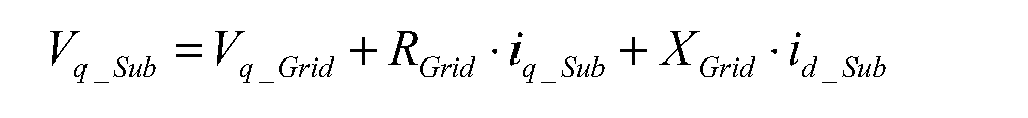
- V q_Sub V q_Grid + R Grid ⁇ i q_Sub + X Grid ⁇ i d_Sub
- V Sub V d_Sub 2 + V q_Sub 2
- Q Calc 3 ⁇ V q_Sub ⁇ i d_Sub - V d_Sub ⁇ i q_Sub
- an iterative method is considered as can be seen in figure 7 .
- a series of prior steps to the iterative process is carried out, so as to obtain the variables necessary for said process. These are:
- the iterative process 15 begins. Said process comprises the following steps:
- a boundary is established that cannot be exceeded by the error between the calculated reactive power and the reference reactive power, for the result to be considered as that corresponding to the stationary state: ⁇ ⁇ Q Calc k - Q ref k ⁇ Boundary ?
- said stationary voltage (V Sub_Est ) is used for the calculation of the error ( ⁇ V) to which a gain is applied (K) for the calculation of the reference reactive power.
- the system of equations resolved in block 9 of figure 4 is such that it includes an equation that equals the reference voltage to the effective value of the voltage measured at the point where the control is carried out, this way imposing a null error in the stationary state.
- V d_Sub V d_Grid + R Grid ⁇ i d_Sub - X Grid ⁇ i q_Sub
- V q_Sub V q_Grid + R Grid ⁇ i q_Sub + X Grid ⁇ i d_Sub
- V Sub V d_Sub 2 + V q_Sub 2
- V Sub V ref
- Q Calc 3 ⁇ V q_Sub ⁇ i d_Sub - V d_Sub ⁇ i q_Sub
- i d_Sub_T arg et k V q_Sub_T arg et k - V q_Grid - R Grid ⁇ i q_Sub k X Grid
- Figure 12 shows the evolution of the substation voltage (V sub ) and the reactive power generated by the wind farm (Q sub_real ) with a voltage control according to a second embodiment of the invention.
- the requirement is to eliminate the voltage error in the stationary state. It is verified that with this type of voltage control, a fast and stable response is achieved that moreover, while the reactive capacity of the wind turbines allows it, eliminates the error in the stationary state.
- the fluctuations that can be observed are due to the reasons set out above.
- a dynamic estimate is made of the grid impedance value (Rgrid) and (Xgrid) based on the electric magnitudes measured at the connection point of the wind farm (V sub , P Global , Q Global , I, cos fi).
- the method of estimation is based on solving a system of equations in the stationary regime, which reflects the behaviour of the grid at three instants that are close in time (t1), (t2), (t3).
- V Grid grid voltage module
- the time cycle for estimating the equivalent grid impedance is substantially greater than for the voltage control.
- records of several consecutive values of grid impedances are saved, in such a way that upon sudden changes in the value of said impedance, the parameters in the voltage control are modified so as to continue guaranteeing the stability of the control.
- one of said parameters is the gain (K) of the control shown in figure 6 .
- control system upon sudden changes in the grid impedance value the control system signals this event by means of an alarm.
- various preset electric grid models may be available.
- Said electric grid models are characterised in a preferred embodiment by a grid impedance that can take on various preset values (provided for example by the operator of the grid to which the wind farm connects during the project definition stage).
- Said preset grid impedance values are the values that the operator has characterised as predominant at the connection point of the wind farm to the grid.
- the system operator provides two impedance values characterised by a resistance and a series impedance: R Grid 1 , X Grid 1 in one case and R Grid 2 , X Grid 2 in the other case.
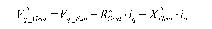
- the solving of the equations on the dq axes (shown below) for the two impedance values, and based on the currents (id, iq) and voltages (Vd_sub, Vq_sub) measured at the connection point at each instant, provides two grid voltage values (V d_Grid 1 , V q_Grid 1 and V d_Grid 2 , V q_Grid 2 ) expressed on dq axes.
- V d_Grid 1 V d_Sub - R Grid 1 ⁇ i d + X Grid 1 ⁇ i q
- V q_Grid 1 V q_Sub - R Grid 1 ⁇ i q + X Grid 1 ⁇ i d
- V d_Grid 2 V d_Sub - R Grid 2 ⁇ i d + X Grid 2 ⁇ i q
- V q_Grid 2 V q_Sub - R Grid 2 ⁇ i q + X Grid 2 ⁇ i d
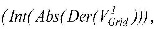
- indexes that are indicative of a change in the grid are defined, that are calculated on the basis of the mobile integral of the absolute value of the derivative of the effective value of each one of the signals of grid voltage calculated with each one of the possible impedances a signal indicative of a change in the grid to which the wind farm is connected.
- the difference between the index indicative of the change in the grid calculated with the current impedance (that used for the estimation of the grid voltage (V Grid ) used in the voltage control according to this invention) and the index indicative of the change in the grid calculated with the rest of the possible impedances is used.
- said difference exceeds a certain threshold, that impedance which gives rise to a greater difference between indexes is selected for the estimation of the grid voltage used in the voltage control.
Abstract
Description
- The following invention, as stated in the heading of this descriptive report, relates to a voltage control method for a power generation plant, and its essential object is the generation of reactive power according to voltage evolution, in such a way that it contributes to stabilising the voltage of the grid.
- A second object of the invention relates to a voltage control system for a power generation plant comprising the abovementioned voltage control method.
- A third object of the invention relates to a wind farm comprising said control system.
- The present specification describes a voltage control method and system for a power generation plant, especially applicable to a wind power generation plant.
- With the rising level of penetration of renewable energy plants in the power grid, these types of generators are being required to offer various auxiliary services, such as voltage and frequency control, in order to ensure their correct integration in the grid.
- In this way, active and reactive power controls have been developed in order to contribute to frequency and voltage stabilisation, respectively.
- This type of generation plant tends to consist of low power generation units (solar panels, wind turbines, etc., in the region of kW up to 10 MW) in comparison with conventional power plants (thermal, nuclear, etc., which can reach up to GW). The coordination and control of all the generation units comprising the renewable generation plant, makes it essential to have communication systems to send the necessary information to each unit.
- Wind power generation in particular, is one of the renewable generation sources that has most increased and at the fastest rate. This type of generator unit has traditionally used two different strategies to control voltage during normal functioning.
- The first strategy has been to incorporate wind generator voltage controllers in the terminal blocks of the wind turbine. One example of this type of control can be found in patent document
US 6965174 B2 . - This type of control has a rapid response and does not require any additional control equipment in the substation, since the wind turbines always incorporate voltage controllers and measurements on terminals.
- However, it has the disadvantage of only controlling local voltage, which is not a relevant value for the power grid provided that it remains within the specified operating ranges. At the same time, voltage at the connection point of the wind farm is not controlled and therefore may be subject to variations.
- The second strategy has been to incorporate controllers for the wind farm, which based on the voltage measured at the connection point of the wind farm, send commands to the wind turbines related to reactive power or the power factor. Examples of this type of control are patent application
EP1433238 and part of what is described in patent documentUS7166928B2 . - The disadvantage of this solution is that in order to obtain a rapid response, a sophisticated computer grid is required connecting the wind farm controller to the wind turbines.
- At the same time, in relation to delays that exist from the moment the measurements are taken and the commands for the generator units are calculated at the substation until the generator units receive them and generate in consequence (digital delays, and delays in communications and systems' response), there can be fluctuations in the voltage and in the generated reactive power.
- Some grid codes specify the level of reactive power that must be generated according to the deviation in voltage, in many cases imposing as a requirement a proportional voltage controller. They also specify the response time required from this controller.
- This type of control can entail the appearance of additional voltage fluctuations depending on the type of grid to which the wind farm is connected (generally with low short-circuit power), the proportionality constant (or droop) required in the control, etc.
- In this invention a voltage control method is proposed for a power generation plant which resolves the inconveniences mentioned above.
- The present specification describes a voltage control method for a power generation plant, characterised in that it comprises the following steps:
- estimating the equivalent grid voltage (VGrid) based on the electric magnitudes measured at the connection point of the power generation plant (VSub, PglobaI, Qglobal, Iglobal, cos fi), and an equivalent model of the power grid to which the power generation plant is connected;
- generation based on said calculated equivalent voltage (VGrid) of a command (Qref) indicative of the reactive power to be produced by the power generation plant.
- By generating the command for reactive power based on the grid voltage (VGrid), which is much more stable than the connection point voltage (VSub), especially in the case of weak grids, the control will be more stable than those in the state of the art, as they are not subject to the fluctuations observed in said connection point voltage, which in consequence generate fluctuations in the reactive power commands. In this way, the voltage at the connection point of the power plant obtained by applying the method of the invention is more stable than those in the state of the art.
- In another aspect of the invention, the reactive power command (Qref) is calculated on the basis of the equivalent grid voltage (VGrid) and has a value that corresponds to the reactive power that the power generation plant must generate in a stationary manner in order to fulfil a preset law of control.
- The fact that the reactive power command corresponds to that which the power generation plant must generate in the stationary state, prevents the delays that exist from the time of taking the measurements and calculating the commands for the generator units in the substation until the generator units receive them and generate in consequence (digital delays and delays in communication and systems' response), from affecting the system's controllability.
- In a first alternative of the invention, the law of control defines the reactive power to be generated (Qref) according to the voltage at the connection point of the power generation plant (VSub) and a reference voltage (Vref).
- According to the first alternative of the invention, it is moreover calculated the voltage at the connection point (VSUb_Est) that will be reached in a stationary manner, on the basis of the equivalent grid voltage (VGrid) and assuming a generated reactive power equal to the command (Qref).
- Said voltage control law, according to the first alternative of the invention, may be imposed by the grid operator responsible for safeguarding the stability of the power system and usually corresponds to a proportional control. In this case, the law of control that defines the required response for the power generation plant includes, in addition to the reference voltage for the voltage at the connection point (Vref), a constant (K) that relates the voltage at the connection point (VSub) and the reactive power (Qref) to be generated by the power generation plant.
- In a second alternative of the invention, the law of control defines the voltage that must be reached in a stationary manner at the point of connection of the wind farm (Vref). In this way, the command (Qref) corresponds to the reactive power that must be generated by the power generation plant in a stationary manner in order to eliminate the error in the stationary state between the command voltage (Vref) and the measured voltage.
- In another aspect of the invention, the control method comprises also the step of dynamically estimating the grid's electrical model based on the electrical magnitudes measured at the power generation plant's point of connection (Vs, P, Q, I, cos fi).
- In this way, changes in the power grid are detected (disconnection of loads or generation units, etc.) which affect the grid's equivalent impedance. Due to the fact that the grid model is used in the voltage control of this invention, the fact of detecting changes in impedance, allows the error made in calculating the reactive power commands to be minimised.
- Said grid electrical model consists of a resistance (R) and a series reactance (X).
- In another aspect of the invention, records of several consecutive values of grid impedance are saved, in such a way that in the face of sudden changes in the value of said impedance, voltage control parameters are modified, such as the response time or proportionality constant (K), in such a way that the stability of the control can continue to be guaranteed.
- Another object of the invention is to provide a voltage control system for a power generation plant, said system comprising means for measuring electric variables at the connection point of the power generation plant and a control unit that calculates from the electric variables a reactive power command (Qref) wherein moreover, the reactive power command is calculated applying a control method according to what has been described above.
- Another object of the invention consists of a wind farm characterised in that it comprises a control system as previously described.
- In order to complement the description that we make next, and with the aim of aiding in a better understanding of the characteristics of the invention, this descriptive report is accompanied by a set of plans, whose figures by way of illustration but not limitation, represent the most characteristic details of the invention.
-
-
Figure 1 . Shows the outline of a power generation plant distributed according to a preferred embodiment. -
Figure 2 . Shows the circuit diagram of a proportional voltage controller, according to the requirements of some grid operators. -
Figure 3 . Shows the circuit diagram of a proportional-integral voltage controller. -
Figure 4 . Shows the circuit diagram of a voltage controller according to a preferred embodiment. -
Figure 5 . Shows an equivalent circuit per phase of the power grid to which the power generation plant is connected. -
Figure 6 . Shows the control circuit diagram according to a preferred embodiment. -
Figure 7 . Shows an iterative solution method according to a preferred embodiment. -
Figure 8 . Shows an iterative solution method according to a preferred embodiment. -
Figure 9 . Shows the evolution of the grid voltage and the power of a wind farm. -
Figure 10 . Shows the evolution of the reference and measured substation voltage and the measured reactive power of a wind farm, according to a conventional voltage control. -
Figure 11 . Shows the evolution of the reference and measured substation voltage and the measured reactive power of a wind farm, according to the voltage control of a preferred embodiment. -
Figure 12 . Shows the evolution of the reference and measured substation voltage and the measured reactive power of a wind farm, according to the voltage control of a preferred embodiment. - In the light of the abovementioned figures and following the adopted numbering, in
figure 1 we can see the outline of a distributed generation plant (for example, a wind farm). - The distributed generation plant comprises, at least, two generation units (or wind turbines) 1, a
park grid 2, acentral control unit 3, a transformer 4, ameasurement unit 5 and acommunication network 6. - Said power generation plant is connected to the
power grid 5 through a transformer 4 which adapts thepark grid voltage 2, or generation voltage level, to the voltage of saidpower grid 7 or voltage level of the distribution or transport grid, as applicable. - The
central control unit 3 receives information from themeasurement unit 5 regarding the active and reactive power generated by the generation plant, the voltage level or current (Pglobal, Qglobal, VSub), measured either on the side of the distributedgeneration plant 2, or on the side of the grid to which the generation plant is connected 7. Said information is used by the central control unit in order to calculate and send commands to the generator units regarding reactive and active power (Qi, Pi) which respond to the voltage and frequency controls that may be required by the corresponding grid operator as applicable. - In
figure 2 we can see the circuit diagram of a proportional voltage controller, according to what is required by certain grid operators as the level of penetration of renewable generation increases. Said controller establishes an amount of reactive power to be generated (Q) by the generation plant proportional to the voltage error (ΔV) existing between the measured voltage (VMed) and the reference voltage (Vref) at the point at which the control voltage is to be carried out. As it is a proportional controller it does not eliminate the steady state voltage error. - An alternative to the above is the proportional-integral controller (PI) shown in
figure 3 . Said controller according to the voltage error (ΔV) establishes an amount of reactive power to be generated by the power generation plant in such a way that the error is eliminated in the stationary state while the generation units are not saturated, in other words, have the capacity to generate all the reactive power that they are commanded to. - However, the integral controller is not required by grid operators, since it can cause fluctuations of reactive power generation and consumption by generators that do not have this type of control active and that are connected to a same point of the grid or are close to each other, due to a disparity in the time constants of the controllers that the different generation units have implemented or to errors in the voltage measurements.
- It is for this reason that most grid operators demand a proportional voltage controller.
- However, the proportional controller can cause fluctuations in voltage, depending on the constant of the required proportional controller and the short circuit power, as well as delays in communications and digital delays and delays associated to the response of reactive generation systems that the generation plant has available (generator units, condenser banks, FACTS-type devices, etc.).
- This fact is caused due to the control being made based exclusively on the voltage measured at the connection point of the generation plant to the grid, which is much more likely to suffer variations with changes in the reactive and active power generated by the generation plant. Therefore, from the moment a change in voltage occurs until the central control detects it and generates the necessary reactive power commands, the generator units can be at a point of reactive power generation that may be opposite to that desired, increasing the voltage error.
- Besides that, from the moment the voltage reaches the reference voltage, until it is communicated to the generator units, they continue to generate reactive power as if there were an error, thus making the control fluctuate.
- The objective of this invention is to eliminate voltage fluctuations in the face of changes in functioning conditions, without having to resort to faster and therefore more expensive equipment and communication systems, so as to obtain a voltage control system of better characteristics than those in the state of the art.
- As can be seen from
figure 4 , in a preferred embodiment for the calculation of the reactive power command (Qref)block 9 uses measurements made in the connection point to the grid of generated active power (Pglobal), reactive power (Qglobal) and voltage (VSub). - Likewise, the reference voltage is used (VSub_ref) appropriate to the point where the voltage control is to be carried out.
- In a preferred embodiment said point corresponds to a point of the grid to which the power generation plant is connected.
- For the calculation of said reactive power reference (Qref)
block 9 additionally uses an equivalent model of the power grid to which the power generation plant is connected. - In
figure 5 it can be seen the equivalent circuit per phase used in a preferred embodiment corresponding to said grid model. The voltage (Vsub ) represents the voltage at the connection point to the grid of the power generation plant, while the voltage (VGrid ) represents the grid voltage and the impedance of the grid is given by a real part (RGrid ) and an imaginary part (jXGrid ). Using Park's transformation, the system of equations on axes (dq) that governs the behaviour of the represented circuit, for a three-phase voltage system is as follows:

- The use of said grid equivalent model is based on the assumption that the most sudden changes in substation voltage (VSub ) are directly related to changes in grid voltage (VGrid )
- The use of these expressions also requires knowledge of the grid impedance (RGrid) and (XGrid). This impedance depends on the consumption generation ratio, which translates into variations in the value of (RGrid) and (XGrid) at each moment and makes use of the above expressions difficult.
- In a preferred embodiment constant grid impedance is assumed, leaving changes in the grid reflected only in the equivalent grid voltage. Said impedance may be evaluated from tests or be provided by the system operator.
- Upon detecting a change in the substation voltage (VSub), the grid voltage (VGrid) that has caused said change must be calculated. To do so, in a preferred embodiment, the currents (id) and (iq) are calculated of the equations system above based on the measurements of active power (Pglobal), reactive power (Qglobal) and voltage (VSub) at the connection point to the grid (PCC), which, taking the substation voltage aligned to the axis (q), can be carried out according to the following expressions:

- In a first preferred embodiment a proportional type control is posed of similar characteristics to that of
figure 2 . However, the proposed control does not directly use the voltage measured at the connection point (VSub_med) for the calculation of the reactive power reference, but rather the voltage at that point corresponding to the stationary state, as shown infigure 6 . - In said
figure 6 one can see the control circuit according to said first preferred embodiment. In it, based on the measurements taken at the connection point to the grid (Pglobal, Qglobal, VSub), block 8 calculates the voltage at the connection point corresponding to the stationary state (Vsub_Est) that will be reached in the new situation. - Based on the error (ΔV) existing between said calculated voltage (VSub_Est) and the reference voltage (VSub_Ref) a calculation is made based on the proportionality constant required by the system's operator of the command for reactive power to be generated by the power generation plant.
- To this effect it is considered in a preferred embodiment that, since the transients in such an event are relatively fast, in the face of a change in voltage of the substation and until the new stationary situation is reached, the active power generated by the wind farm (PGlobal) is not substantially modified. Therefore, the active power generated in the future stationary state will correspond to that measured at that instant. At the same time, it is also considered that the grid voltage (VGrid) is not substantially modified as a consequence of the control of the substation voltage, instead, the variables that will have changed in the stationary state will be the generated reactive power (QGlobal) and as a result, the substation voltage (VSub).
- In this way, the control system provides, upon a change in the system's variables, the reference value of the reactive power (Qref) related to the new value of stationary voltage (Vsub_Est). When this command value of reactive power is applied as reference (Qref) to the
wind farm 10 any fluctuation will be avoided, since the control does not take into account what has happened with the variables during the transient. This is how the problems resulting from delays in communication and response times of the generator units are overcome. - In a preferred embodiment, the group of equations used in
block 9 offigure 6 for the calculation of the substation voltage (VSub) in the future stationary state is as follows:


- To resolve the above system of equations, in a preferred embodiment an iterative method is considered as can be seen in
figure 7 .
In block 11 a series of prior steps to the iterative process is carried out, so as to obtain the variables necessary for said process. These are: - Obtaining
measurements 12 of active power generated by the wind farm (PGlobal), total generated reactive power (QGlobal) and voltage at the connection point to the power grid or at the point at which the voltage control is to be carried out (VSub). - Calculation of the current 13 at the point at which the voltage control on axes is to be carried out (dq), (id_Sub) and (iq_Sub), based on the measurements of active power (Pglobal), reactive power (Qglobal) and voltage (VSub) at the connection point to the grid (PCC), all of which, taking said voltage aligned with the axis (q), according to the following expressions:

- Calculation of the
grid voltage 14 on axes (dq), (Vd_Grid) and (Vq_Grid), according to the equations that govern the behaviour of the equivalent circuit per phase of the electrical grid to which the wind farm is connected shown infigure 4 , in other words: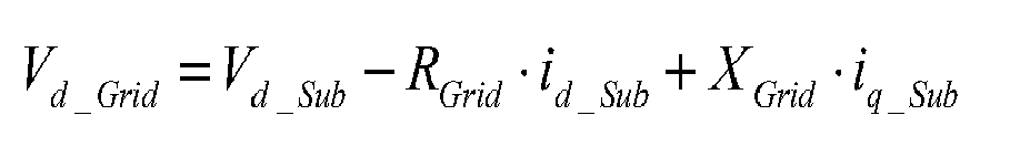

- Of the variables measured, calculated or estimated in
block 11, the following are presumed constant throughout the iterative process: - Total generated power (Pglobal), which follows a slow dynamic. It is considered that in the face of a change in grid voltage and until the stationary subsequent to said change is reached, the variable that changes in consequence is the generated reactive power (Qglobal).
- The grid voltage calculated on axes (dq), (Vd_Grid) and (Vq_Grid). It is presumed that the generation or consumption of reactive power corresponding to the voltage control does not have an influence on said grid voltage, instead exclusively on the substation voltage.
- Once the calculations in
block 11 have been made, theiterative process 15 begins. Said process comprises the following steps: - Calculation in
block 16 of the reactive powersand based on the following expressions, where superscript K identifies the iteration number:


- Checking in
block 17 that the calculated reactive power corresponds effectively to the stationary state. To this effect, the calculation is made of the difference between the reactive power calculated on the basis of the system's currents and voltagesand the reference reactive power corresponding to said voltages Said difference is referred to as error:

- In a preferred embodiment a boundary is established that cannot be exceeded by the error between the calculated reactive power and the reference reactive power, for the result to be considered as that corresponding to the stationary state:

- If the error is greater than the established boundary, a new iteration is initiated.
- Calculation in
block 18 of a new reactive powerwhich is calculated as a linear combination of and
and with a view to the system converging, in the following manner:
- Calculation in block 19 of the currents and
 which are established for the new situation of reactive power
 taking into account that the active power remains constant, on the basis of the following expressions:


- Calculation in
block 20 of the voltages at the point at which the control is carried out, based on the equations that model the behaviour of the grid to which the wind farm is connected and the previously calculated currents, taking into account that (V d_Grid ) and (Vq_Grid ) do not change in respect of the step prior to the iterative process:

- With the voltages and currents, within the
iterative process 15, a calculation is made once more of the reference reactive power and the calculated reactive power, and the iterative process continues in a similar way. - As can be seen in
figure 6 , in a preferred embodiment said stationary voltage (VSub_Est) is used for the calculation of the error (ΔV) to which a gain is applied (K) for the calculation of the reference reactive power. - In a second preferred embodiment, the system of equations resolved in
block 9 offigure 4 is such that it includes an equation that equals the reference voltage to the effective value of the voltage measured at the point where the control is carried out, this way imposing a null error in the stationary state. - From the solving of the system of equations a production of reactive power is obtained (QCalc) that eliminates the error in the stationary state and that will be the one issued as the reactive power command (Qref) in order to carry out the voltage control.


- In order to solve the system of equations above, in a preferred embodiment an iterative method is considered as can be seen in
figure 8 . - In the previous step, related to block 11, at the beginning of the iterative process, the calculations coincide with those explained previously for
figure 7 , in the same way as the hypotheses of the iterative process coincide: the generated power (PGlobal) and the grid voltage (Vd_Grid) and (Vq_Grid) remain constant from one step to another of the iterative process. - Once the prior calculations have been made in 11, the
iterative process 15 begins. Said process comprises the following steps: - Checking in
block 22 that the calculated substation voltage (or measured in the case of the first iteration) and the reference substation voltage are approximately the same, in other words, that the error existing between them is less than a determined boundary level.
- Calculation in
block 23 of the target substation voltage on the axis (q)based on the command voltage (Vref). To this effect it is considered that the voltage on axis d does not change, rather it coincides with that of the previous iteration. In other words:

- Based on said voltage and the grid model to which the park is connected also calculated in
block 23 is the target current on the axis (d) associated to the generation of reactive power,according to the following expression:

- To this effect it is considered that the current on the axis (q) remains constant.
- On the basis of said target current on the axis (d) and target voltage on the axis (q) in
block 24 the target associated reactive power is calculated

- Calculation in
block 25 of the currentsand that are established for the new situation of reactive power
 bearing in mind that the active power remains constant, on the basis of the following expressions:


- Calculation in
block 26 of the voltages at the point where the control is carried out, on the basis of the equations that model the behaviour of the grid to which the wind farm is connected and the previously calculated currents, bearing in mind that (Vd_Grid ) and (Vq_Grid ) do not change in respect of the prior step of the iterative process:

- If effectively in
block 22 it is verified that
iterative process 15 concludes and inblock 27 the reactive power reference (Qref ) is generated, equalling it to the target reactive powerthus achieving a reactive power reference that eliminates the voltage error in the future stationary state, in a much faster way than a conventional proportional-integral (PI) controller.
- The blocks described above may correspond to different devices of which a control unit is made up, or alternatively a calculating unit may be adapted to carry out the calculations described above, with each described block being a stage of said calculation.
- In a preferred embodiment a control unit of a wind farm is a programmable device set up to run the method described above. Both iterative methods are easy to implement in substation digital control systems, (PLC), and require reduced calculation times.
- In a preferred embodiment a control system for a wind farm comprises means for measuring electrical variables at the connection point of the power generation plant with said control unit.
- In
figure 9 one can see the active power generated by a wind farm with an installed rating of 27 MW and the equivalent grid voltage of the system. A fast variation in active power is considered at the same time as a certain noise in grid voltage, to analyse the robustness of control systems. In this generation situation the response of different types of voltage controls are analysed. -
Figure 10 shows the evolution of the substation's voltage (Vsub) and the reactive power (Qsub_real) generated by the wind farm with a conventional voltage control. The response required by the system's operator is such that upon a deviation in voltage (ΔV) of 4%, the wind turbines must generate all the reactive power that they are capable of, with the adequate sign, and with a speed of response of one second. It is verified that with this type of voltage control a good response is not achieved, since due to delays, characteristics of the grid, and the type of response required by the operator, the system becomes fluctuating. -
Figure 11 shows the evolution in the substation voltage (Vsub) and the reactive power generated by the wind farm (Qsub_real) with a voltage control according to the first embodiment of the invention. The response required by the system's operator is such that upon a deviation in voltage (ΔV) of 4%, the wind turbines must generate all the reactive power that they are capable of, with the adequate sign, and with a speed of response of one second. It is verified that with this type of voltage control, a fast and stable response is achieved, since from the first instant the reactive power command is calculated and sent that is suitable for the stationary state of the voltage. The fluctuations that are observed are due to the weakness of the grid to which the wind farm is connected and to the fluctuations in generated active power and grid voltage. Moreover, due to the characteristics of the required response the error is not eliminated in the stationary state. -
Figure 12 shows the evolution of the substation voltage (Vsub) and the reactive power generated by the wind farm (Qsub_real) with a voltage control according to a second embodiment of the invention. In this case, the requirement is to eliminate the voltage error in the stationary state. It is verified that with this type of voltage control, a fast and stable response is achieved that moreover, while the reactive capacity of the wind turbines allows it, eliminates the error in the stationary state. The fluctuations that can be observed are due to the reasons set out above. - In a preferred embodiment a dynamic estimate is made of the grid impedance value (Rgrid) and (Xgrid) based on the electric magnitudes measured at the connection point of the wind farm (Vsub, PGlobal, QGlobal, I, cos fi).
- The method of estimation is based on solving a system of equations in the stationary regime, which reflects the behaviour of the grid at three instants that are close in time (t1), (t2), (t3). For the execution of the grid estimate it is assumed that at said instants the grid voltage module (VGrid), as well as the grid impedance remain constant.
- Said system of equations, with the electric variables expressed on axes (dq) synchronised at the frequency of the grid and the q axis being aligned with the substation voltage (Vsub), remains as follows:


- From the solution of the above system of equations the values of resistance (RGrid) and inductance (XGrid) of the equivalent grid model used for the voltage control that is the object of this invention.
- In a preferred embodiment the time cycle for estimating the equivalent grid impedance is substantially greater than for the voltage control.
- In a preferred embodiment records of several consecutive values of grid impedances are saved, in such a way that upon sudden changes in the value of said impedance, the parameters in the voltage control are modified so as to continue guaranteeing the stability of the control. In a preferred embodiment one of said parameters is the gain (K) of the control shown in
figure 6 . - In a preferred embodiment, upon sudden changes in the grid impedance value the control system signals this event by means of an alarm.
- In an alternative embodiment various preset electric grid models may be available. Said electric grid models are characterised in a preferred embodiment by a grid impedance that can take on various preset values (provided for example by the operator of the grid to which the wind farm connects during the project definition stage). Said preset grid impedance values are the values that the operator has characterised as predominant at the connection point of the wind farm to the grid.
- In this case the equations that govern the behaviour of the circuit represented in
figure 5 are resolved at each instant for all the impedance values provided by the electrical operator, thus calculating the grid voltage for each impedance value and taking, for the wind farm's voltage control, the value of the grid voltage obtained at each instant that results in a more stable value. - In a particular case of said alternative embodiment, the system operator provides two impedance values characterised by a resistance and a series impedance: RGrid 1, XGrid 1 in one case and RGrid 2, XGrid 2 in the other case. The solving of the equations on the dq axes (shown below) for the two impedance values, and based on the currents (id, iq) and voltages (Vd_sub, Vq_sub) measured at the connection point at each instant, provides two grid voltage values (Vd_Grid 1, Vq_Grid 1 and Vd_Grid 2, Vq_Grid 2) expressed on dq axes.


- In order to determine which is the most stable value of grid voltage at each instant for use in the voltage control, in a preferred embodiment the variance is calculated for an established period of time of each one of the signals of grid voltages (Vd_Grid 1, Vq_Grid 1 and Vd_Grid 2, Vq_Grid 2) obtained with each one of the preset impedances, or any other known method for quantifying a signal's variability.
- In an alternative embodiment, indexes that are indicative of a change in the grid are defined, that are calculated on the basis of the mobile integral of the absolute value of the derivative of the effective value of each one of the signals of grid voltage calculated with each one of the possible impedancesa signal indicative of a change in the grid to which the wind farm is connected. The calculation of the aforementioned indexes is done as follows:


- When a change occurs in the grid, it affects either the voltage of the equivalent model or the impedance thereof and both changes are reflected in the indexes indicative of the change in the grid


- However, when the change in the grid affects the voltage of the equivalent model, said indexes
 evolve in a similar manner, whereas if the change in the grid affects the impedance of the equivalent model, the index calculated
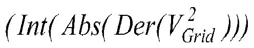
 with the inadequate impedance, will grow to a greater extent than the signal calculated with the correct impedance.
- In order to distinguish between when the change occurs in the grid voltage and when it corresponds to a change in impedance, as a signal indicative of a change in impedance, the difference between the index indicative of the change in the grid calculated with the current impedance (that used for the estimation of the grid voltage (VGrid) used in the voltage control according to this invention) and the index indicative of the change in the grid calculated with the rest of the possible impedances is used. When said difference exceeds a certain threshold, that impedance which gives rise to a greater difference between indexes is selected for the estimation of the grid voltage used in the voltage control.

Claims (12)
- VOLTAGE CONTROL METHOD OF A POWER GENERATION PLANT, characterised in that it comprises the following steps:- estimating the equivalent grid voltage (VGrid) based on electric magnitudes measured at the connection point of the power generation plant (VSub, Pglobal, Qglobal, Iglobal, cos fi), and an equivalent model of a power grid to which the power generation plant is connected;- generating on the basis of said estimated equivalent voltage (Vgrid) a command (Oref) indicative of reactive power to be produced by the power generation plant.
- VOLTAGE CONTROL METHOD OF A POWER GENERATION PLANT, according to claim 1, characterised in that the reactive power command (Qref) is calculated on the basis of the equivalent grid voltage (VGrid) and has a value that corresponds to the reactive power that the power generation plant must generate in a stationary manner in order to fulfil a preset law of control.
- VOLTAGE CONTROL METHOD OF A POWER GENERATION PLANT, according to claim 2, characterised in that the preset law of control defines the reactive power to be generated (Qref) according to a voltage at the connection point of the power generation plant (VSub) and a reference voltage (Vref).
- VOLTAGE CONTROL METHOD OF A POWER GENERATION PLANT, according to claim 3, characterised in that it is calculated the voltage at the connection point (VSub_Est) that will be reached in a stationary manner, on the basis of the equivalent grid voltage (VGrid) and assuming a generated reactive power equal to the command (Qref).
- VOLTAGE CONTROL METHOD OF A POWER GENERATION PLANT, according to claim 3, characterised in that the preset law of control is defined by means of a reference voltage for the voltage at the connection point (Vref) and a constant (K) that relates the voltage at the connection point (VSub) and the reactive power to be generated (Qref).
- VOLTAGE CONTROL METHOD OF A POWER GENERATION PLANT, according to claim 2, characterised in that the law of control defines the voltage that must be reached in a stationary manner at the connection point of the park (Vref).
- VOLTAGE CONTROL METHOD OF A POWER GENERATION PLANT, according to any of the preceding claims, characterised in that said method comprises in addition the step of dynamically estimating the grid model on the basis of the electric magnitudes measured at the connection point of the power generation plant (Vs, P, Q, I, cos fi).
- VOLTAGE CONTROL METHOD OF A POWER GENERATION PLANT, according to claim 7, characterised in that said electric grid model consists of a resistance (R) and a series reactance (X).
- VOLTAGE CONTROL METHOD OF A POWER GENERATION PLANT, according to claim 7, characterised in that records of several consecutive values of grid impedances are saved, in such a way that upon sudden changes in the value of said impedance, parameters are modified in the voltage control so as to continue to guarantee the stability of the control.
- VOLTAGE CONTROL METHOD OF A POWER GENERATION PLANT, according to any of claims 1 to 6, characterised in that said method comprises also the step of calculating the equivalent grid voltage (VGrid) for various preset electric grid models and the step of selecting at each moment a most stable equivalent grid voltage (VGrid).
- VOLTAGE CONTROL SYSTEM OF A POWER GENERATION PLANT, which comprises means for measuring electric variables at the connection point of the power generation plant and a control unit that calculates on the basis of the electric variables a command for reactive power (Qref), characterised in that the reactive power command is calculated by applying a control method according to any of claims 1 to 10.
- WIND FARM, characterised in that it comprises the control system described in claim 11.
Applications Claiming Priority (1)
| Application Number | Priority Date | Filing Date | Title |
|---|---|---|---|
| ES200900729A ES2382786B1 (en) | 2009-03-17 | 2009-03-17 | METHOD AND VOLTAGE CONTROL SYSTEM OF AN ELECTRICAL GENERATION CENTER AND WIND FARM |
Publications (3)
| Publication Number | Publication Date |
|---|---|
| EP2236820A2 true EP2236820A2 (en) | 2010-10-06 |
| EP2236820A3 EP2236820A3 (en) | 2014-08-13 |
| EP2236820B1 EP2236820B1 (en) | 2017-04-19 |
Family
ID=42315657
Family Applications (1)
| Application Number | Title | Priority Date | Filing Date |
|---|---|---|---|
| EP10156701.4A Active EP2236820B1 (en) | 2009-03-17 | 2010-03-17 | Voltage control method and system for a power generation plant and wind farm |
Country Status (3)
| Country | Link |
|---|---|
| US (1) | US9257845B2 (en) |
| EP (1) | EP2236820B1 (en) |
| ES (2) | ES2382786B1 (en) |
Cited By (11)
| Publication number | Priority date | Publication date | Assignee | Title |
|---|---|---|---|---|
| WO2013097862A3 (en) * | 2011-12-29 | 2014-04-24 | Vestas Wind Systems A/S | A wind turbine generator |
| CN103956767A (en) * | 2014-02-21 | 2014-07-30 | 国家电网公司 | Wake-effect-considering wind power plant grid-connection stability analysis method |
| EP2875562A1 (en) * | 2012-07-20 | 2015-05-27 | Wobben Properties GmbH | Method for controlling a wind farm |
| EP2636894A3 (en) * | 2012-03-06 | 2015-07-01 | RWE Innogy GmbH | Offshore wind energy system |
| EP2874273A4 (en) * | 2012-07-10 | 2016-03-30 | Hitachi Ltd | Power system control system, and power system control method |
| WO2017062097A1 (en) * | 2015-10-07 | 2017-04-13 | General Electric Company | Solar power conversion system and method |
| WO2017223222A1 (en) * | 2016-06-21 | 2017-12-28 | General Electric Company | System and method for controlling a power generating unit |
| US9997921B2 (en) | 2015-10-07 | 2018-06-12 | General Electric Company | Solar power conversion system and method |
| CN109960823A (en) * | 2017-12-22 | 2019-07-02 | 北京金风科创风电设备有限公司 | Equivalent wind speed determination method and equipment of wind generating set |
| EP3505753A1 (en) * | 2017-12-29 | 2019-07-03 | Acciona Windpower, S.A. | Method for operating electrical machines |
| US10985611B2 (en) | 2019-04-10 | 2021-04-20 | General Electric Company | System and method for estimating grid strength |
Families Citing this family (22)
| Publication number | Priority date | Publication date | Assignee | Title |
|---|---|---|---|---|
| US9478987B2 (en) * | 2009-11-10 | 2016-10-25 | Siemens Aktiengesellschaft | Power oscillation damping employing a full or partial conversion wind turbine |
| JP5740561B2 (en) * | 2010-04-27 | 2015-06-24 | パナソニックIpマネジメント株式会社 | Voltage control apparatus, voltage control method, and voltage control program |
| US9222466B2 (en) * | 2010-08-13 | 2015-12-29 | Vestas Wind Systems A/S | Wind-power production with reduced power fluctuations |
| US8610306B2 (en) | 2011-07-29 | 2013-12-17 | General Electric Company | Power plant control system and method for influencing high voltage characteristics |
| US9252596B2 (en) | 2011-11-28 | 2016-02-02 | General Electric Company | System and method for reactive power compensation in power networks |
| US9046077B2 (en) * | 2011-12-28 | 2015-06-02 | General Electric Company | Reactive power controller for controlling reactive power in a wind farm |
| DE102012212364A1 (en) | 2012-07-13 | 2014-01-16 | Wobben Properties Gmbh | Method and device for feeding electrical energy into an electrical supply network |
| US9081407B2 (en) * | 2012-12-21 | 2015-07-14 | General Electric Company | Voltage regulation system and method |
| CN103095207B (en) * | 2013-01-16 | 2014-11-26 | 浙江省电力公司电力科学研究院 | Method and system of equivalent impedance compensation |
| CN103558768B (en) * | 2013-08-12 | 2016-09-21 | 清华大学 | A kind of based on the equivalent modeling method of wind speed distribution characteristics in wind energy turbine set |
| GB201411004D0 (en) | 2014-06-20 | 2014-08-06 | Univ Dublin | Method for controlling power distribution |
| CN104281192B (en) * | 2014-09-29 | 2016-06-22 | 许继电气股份有限公司 | A kind of photovoltaic DC-to-AC converter active power dispatch method |
| JP6478588B2 (en) * | 2014-11-26 | 2019-03-06 | 三菱電機株式会社 | Voltage control device and voltage measurement device |
| US9831810B2 (en) * | 2015-03-10 | 2017-11-28 | General Electric Company | System and method for improved reactive power speed-of-response for a wind farm |
| US9970417B2 (en) | 2016-04-14 | 2018-05-15 | General Electric Company | Wind converter control for weak grid |
| US10027118B2 (en) * | 2016-05-19 | 2018-07-17 | General Electric Company | System and method for balancing reactive power loading between renewable energy power systems |
| WO2018068799A1 (en) | 2016-10-12 | 2018-04-19 | Vestas Wind Systems A/S | Improvements relating to reactive power control in wind power plants |
| WO2018201105A1 (en) * | 2017-04-27 | 2018-11-01 | Massachusetts Institute Of Technology | Plug-and-play reconfigurable electric power microgrids |
| US11353908B2 (en) * | 2018-02-05 | 2022-06-07 | Mitsubishi Electric Corporation | Centralized voltage control apparatus and centralized voltage control system |
| DE102018122586A1 (en) * | 2018-09-14 | 2020-03-19 | Wobben Properties Gmbh | Wind farm with a stabilization unit and such a stabilization unit |
| CN109888820B (en) * | 2019-02-14 | 2021-11-02 | 国网甘肃省电力公司嘉峪关供电公司 | Method for calculating the short-circuit current contribution of a new energy bank |
| EP4128478A1 (en) | 2020-04-02 | 2023-02-08 | Dominion Energy, Inc. | Electrical grid control systems and methods using dynamically mapped effective impedance |
Citations (3)
| Publication number | Priority date | Publication date | Assignee | Title |
|---|---|---|---|---|
| EP1433238A1 (en) | 2001-09-28 | 2004-06-30 | Aloys Wobben | Method for operating a wind park |
| US6965174B2 (en) | 2001-04-24 | 2005-11-15 | Aloys Wobben | Method for operating a wind turbine |
| US7166928B2 (en) | 2003-09-03 | 2007-01-23 | General Electric Company | Voltage control for wind generators |
Family Cites Families (11)
| Publication number | Priority date | Publication date | Assignee | Title |
|---|---|---|---|---|
| AU2860095A (en) * | 1994-07-22 | 1996-02-22 | Electric Power Research Institute, Inc. | Transmission line power controller with a continuously controllable voltage source responsive to a real power demand and a reactive power demand |
| DE19516604A1 (en) * | 1995-05-09 | 1997-02-13 | Siemens Ag | Method and device for the static and dynamic support of a mains voltage by means of a static compensation device with a self-commutated converter |
| US6924565B2 (en) * | 2003-08-18 | 2005-08-02 | General Electric Company | Continuous reactive power support for wind turbine generators |
| EP1764894A1 (en) * | 2005-09-19 | 2007-03-21 | ABB Schweiz AG | Method for detecting islanding operation of a distributed generator |
| US7346462B2 (en) * | 2006-03-29 | 2008-03-18 | General Electric Company | System, method, and article of manufacture for determining parameter values associated with an electrical grid |
| US7505833B2 (en) * | 2006-03-29 | 2009-03-17 | General Electric Company | System, method, and article of manufacture for controlling operation of an electrical power generation system |
| US7983799B2 (en) * | 2006-12-15 | 2011-07-19 | General Electric Company | System and method for controlling microgrid |
| WO2008106550A2 (en) * | 2007-02-27 | 2008-09-04 | Osisoft, Inc. | Impedance measurement of a power line |
| BRPI0819413A2 (en) | 2007-12-28 | 2015-05-05 | Vestas Wind Sys As | "method for controlling a grid voltage and method for determining the process gain of a voltage controller" |
| ES2545606T3 (en) * | 2008-06-30 | 2015-09-14 | Vestas Wind Systems A/S | Procedure and system for operating a wind power plant comprising a number of wind turbine generators |
| US8041465B2 (en) * | 2008-10-09 | 2011-10-18 | General Electric Company | Voltage control at windfarms |
-
2009
- 2009-03-17 ES ES200900729A patent/ES2382786B1/en not_active Expired - Fee Related
-
2010
- 2010-03-16 US US12/724,945 patent/US9257845B2/en active Active
- 2010-03-17 EP EP10156701.4A patent/EP2236820B1/en active Active
- 2010-03-17 ES ES10156701.4T patent/ES2634112T3/en active Active
Patent Citations (3)
| Publication number | Priority date | Publication date | Assignee | Title |
|---|---|---|---|---|
| US6965174B2 (en) | 2001-04-24 | 2005-11-15 | Aloys Wobben | Method for operating a wind turbine |
| EP1433238A1 (en) | 2001-09-28 | 2004-06-30 | Aloys Wobben | Method for operating a wind park |
| US7166928B2 (en) | 2003-09-03 | 2007-01-23 | General Electric Company | Voltage control for wind generators |
Cited By (21)
| Publication number | Priority date | Publication date | Assignee | Title |
|---|---|---|---|---|
| CN104094493A (en) * | 2011-12-29 | 2014-10-08 | 维斯塔斯风力系统集团公司 | A wind turbine generator |
| US9593667B2 (en) | 2011-12-29 | 2017-03-14 | Vestas Wind Systems A/S | Wind turbine generator |
| WO2013097862A3 (en) * | 2011-12-29 | 2014-04-24 | Vestas Wind Systems A/S | A wind turbine generator |
| EP2636894A3 (en) * | 2012-03-06 | 2015-07-01 | RWE Innogy GmbH | Offshore wind energy system |
| EP3101274A1 (en) * | 2012-03-06 | 2016-12-07 | RWE Innogy GmbH | Wind energy system |
| EP2874273A4 (en) * | 2012-07-10 | 2016-03-30 | Hitachi Ltd | Power system control system, and power system control method |
| EP2875562B1 (en) * | 2012-07-20 | 2022-11-30 | Wobben Properties GmbH | Method for controlling a wind farm |
| EP2875562A1 (en) * | 2012-07-20 | 2015-05-27 | Wobben Properties GmbH | Method for controlling a wind farm |
| EP4181339A1 (en) | 2012-07-20 | 2023-05-17 | Wobben Properties GmbH | Method for controlling a wind farm |
| CN103956767A (en) * | 2014-02-21 | 2014-07-30 | 国家电网公司 | Wake-effect-considering wind power plant grid-connection stability analysis method |
| CN103956767B (en) * | 2014-02-21 | 2016-04-20 | 国家电网公司 | A kind of wind farm grid-connected method for analyzing stability considering wake effect |
| US9847647B2 (en) | 2015-10-07 | 2017-12-19 | General Electric Company | Solar power conversion system and method |
| US9997921B2 (en) | 2015-10-07 | 2018-06-12 | General Electric Company | Solar power conversion system and method |
| WO2017062097A1 (en) * | 2015-10-07 | 2017-04-13 | General Electric Company | Solar power conversion system and method |
| WO2017223222A1 (en) * | 2016-06-21 | 2017-12-28 | General Electric Company | System and method for controlling a power generating unit |
| US11619206B2 (en) | 2016-06-21 | 2023-04-04 | General Electric Company | System and method for controlling a power generating unit |
| CN109960823A (en) * | 2017-12-22 | 2019-07-02 | 北京金风科创风电设备有限公司 | Equivalent wind speed determination method and equipment of wind generating set |
| CN109960823B (en) * | 2017-12-22 | 2023-04-07 | 北京金风科创风电设备有限公司 | Equivalent wind speed determination method and equipment of wind generating set |
| EP3505753A1 (en) * | 2017-12-29 | 2019-07-03 | Acciona Windpower, S.A. | Method for operating electrical machines |
| US10954918B2 (en) | 2017-12-29 | 2021-03-23 | Nordex Energy Spain, S.A. | Method for operating electrical machines |
| US10985611B2 (en) | 2019-04-10 | 2021-04-20 | General Electric Company | System and method for estimating grid strength |
Also Published As
| Publication number | Publication date |
|---|---|
| EP2236820B1 (en) | 2017-04-19 |
| US9257845B2 (en) | 2016-02-09 |
| ES2382786B1 (en) | 2013-05-07 |
| EP2236820A3 (en) | 2014-08-13 |
| US20100237834A1 (en) | 2010-09-23 |
| ES2382786A1 (en) | 2012-06-13 |
| ES2634112T3 (en) | 2017-09-26 |
Similar Documents
| Publication | Publication Date | Title |
|---|---|---|
| EP2236820B1 (en) | Voltage control method and system for a power generation plant and wind farm | |
| US9985561B2 (en) | Method and apparatus for feeding electric energy into an electric supply grid | |
| US10063059B2 (en) | Wind power plant with optimal power output | |
| US11245261B2 (en) | Method for controlling a wind power plant | |
| EP2711543B1 (en) | Operating a wind turbine and a wind farm in different grid strength | |
| US11619206B2 (en) | System and method for controlling a power generating unit | |
| US20140306534A1 (en) | Pmu based distributed generation control for microgrid during islanding process | |
| CN101911424A (en) | Method for controlling a grid voltage | |
| US20220399721A1 (en) | Method for grid impedance and dynamics estimation | |
| US11855458B2 (en) | Current injection in wind power plants | |
| KR101520248B1 (en) | Method and Apparatus for Controlling Doubly-fed Induction Generator using Adaptive Backstepping Control Scheme | |
| Miret et al. | PI‐based controller for low‐power distributed inverters to maximise reactive current injection while avoiding over voltage during voltage sags | |
| US20230417220A1 (en) | Methods and systems for improving grid stability | |
| US11171487B2 (en) | Voltage control in wind power plants | |
| CN111273632A (en) | SVG controller parameter identification method based on RTDS test data | |
| CN113013913B (en) | Reactive voltage control system and method for wind farm | |
| US11437825B2 (en) | Hybrid renewable power plant | |
| CN110970915B (en) | Control method and device for grid-connected voltage of wind generating set | |
| US10727843B2 (en) | Method for operating a wind turbine | |
| EP3179594A1 (en) | Dynamic control method of power injected into the power grid by distributed generators | |
| Melkior et al. | The reliability of the system with wind power generation | |
| Liang et al. | Measurement-Based Characteristic Curves at Point of Interconnection of Wind Farms | |
| Patel et al. | Improved DFIG control with decoupled control to enhance LVRT response | |
| Souza et al. | Robustness Comparison of Synthetic Inertia Strategies for Doubly Fed Induction Generators under Different Operating Conditions | |
| CN116073394A (en) | SVG electromechanical transient model parameter identification method and system |
Legal Events
| Date | Code | Title | Description |
|---|---|---|---|
| PUAI | Public reference made under article 153(3) epc to a published international application that has entered the european phase |
Free format text: ORIGINAL CODE: 0009012 |
|
| AK | Designated contracting states |
Kind code of ref document: A2 Designated state(s): AT BE BG CH CY CZ DE DK EE ES FI FR GB GR HR HU IE IS IT LI LT LU LV MC MK MT NL NO PL PT RO SE SI SK SM TR |
|
| RTI1 | Title (correction) |
Free format text: VOLTAGE CONTROL METHOD AND SYSTEM FOR A POWER GENERATION PLANT AND WIND FARM |
|
| PUAL | Search report despatched |
Free format text: ORIGINAL CODE: 0009013 |
|
| AK | Designated contracting states |
Kind code of ref document: A3 Designated state(s): AT BE BG CH CY CZ DE DK EE ES FI FR GB GR HR HU IE IS IT LI LT LU LV MC MK MT NL NO PL PT RO SE SI SK SM TR |
|
| RIC1 | Information provided on ipc code assigned before grant |
Ipc: F03D 9/00 20060101ALI20140708BHEP Ipc: F03D 7/02 20060101ALI20140708BHEP Ipc: H02J 3/38 20060101ALI20140708BHEP Ipc: F03D 7/04 20060101AFI20140708BHEP Ipc: H02J 3/18 20060101ALI20140708BHEP |
|
| 17P | Request for examination filed |
Effective date: 20150213 |
|
| RBV | Designated contracting states (corrected) |
Designated state(s): AT BE BG CH CY CZ DE DK EE ES FI FR GB GR HR HU IE IS IT LI LT LU LV MC MK MT NL NO PL PT RO SE SI SK SM TR |
|
| 17Q | First examination report despatched |
Effective date: 20160202 |
|
| REG | Reference to a national code |
Ref country code: DE Ref legal event code: R079 Ref document number: 602010041595 Country of ref document: DE Free format text: PREVIOUS MAIN CLASS: F03D0007040000 Ipc: G05F0001700000 |
|
| GRAP | Despatch of communication of intention to grant a patent |
Free format text: ORIGINAL CODE: EPIDOSNIGR1 |
|
| STAA | Information on the status of an ep patent application or granted ep patent |
Free format text: STATUS: GRANT OF PATENT IS INTENDED |
|
| RIC1 | Information provided on ipc code assigned before grant |
Ipc: F03D 9/00 20160101ALI20161116BHEP Ipc: F03D 7/02 20060101ALI20161116BHEP Ipc: G05F 1/70 20060101AFI20161116BHEP Ipc: H02J 3/38 20060101ALI20161116BHEP Ipc: H02J 3/18 20060101ALI20161116BHEP |
|
| INTG | Intention to grant announced |
Effective date: 20161212 |
|
| GRAS | Grant fee paid |
Free format text: ORIGINAL CODE: EPIDOSNIGR3 |
|
| GRAA | (expected) grant |
Free format text: ORIGINAL CODE: 0009210 |
|
| STAA | Information on the status of an ep patent application or granted ep patent |
Free format text: STATUS: THE PATENT HAS BEEN GRANTED |
|
| AK | Designated contracting states |
Kind code of ref document: B1 Designated state(s): AT BE BG CH CY CZ DE DK EE ES FI FR GB GR HR HU IE IS IT LI LT LU LV MC MK MT NL NO PL PT RO SE SI SK SM TR |
|
| REG | Reference to a national code |
Ref country code: GB Ref legal event code: FG4D |
|
| REG | Reference to a national code |
Ref country code: CH Ref legal event code: EP |
|
| REG | Reference to a national code |
Ref country code: AT Ref legal event code: REF Ref document number: 886533 Country of ref document: AT Kind code of ref document: T Effective date: 20170515 |
|
| REG | Reference to a national code |
Ref country code: IE Ref legal event code: FG4D |
|
| REG | Reference to a national code |
Ref country code: DE Ref legal event code: R096 Ref document number: 602010041595 Country of ref document: DE |
|
| REG | Reference to a national code |
Ref country code: SE Ref legal event code: TRGR |
|
| REG | Reference to a national code |
Ref country code: NL Ref legal event code: MP Effective date: 20170419 |
|
| REG | Reference to a national code |
Ref country code: LT Ref legal event code: MG4D |
|
| REG | Reference to a national code |
Ref country code: AT Ref legal event code: MK05 Ref document number: 886533 Country of ref document: AT Kind code of ref document: T Effective date: 20170419 |
|
| REG | Reference to a national code |
Ref country code: NO Ref legal event code: T2 Effective date: 20170419 |
|
| REG | Reference to a national code |
Ref country code: ES Ref legal event code: FG2A Ref document number: 2634112 Country of ref document: ES Kind code of ref document: T3 Effective date: 20170926 |
|
| PG25 | Lapsed in a contracting state [announced via postgrant information from national office to epo] |
Ref country code: NL Free format text: LAPSE BECAUSE OF FAILURE TO SUBMIT A TRANSLATION OF THE DESCRIPTION OR TO PAY THE FEE WITHIN THE PRESCRIBED TIME-LIMIT Effective date: 20170419 |
|
| PG25 | Lapsed in a contracting state [announced via postgrant information from national office to epo] |
Ref country code: HR Free format text: LAPSE BECAUSE OF FAILURE TO SUBMIT A TRANSLATION OF THE DESCRIPTION OR TO PAY THE FEE WITHIN THE PRESCRIBED TIME-LIMIT Effective date: 20170419 Ref country code: GR Free format text: LAPSE BECAUSE OF FAILURE TO SUBMIT A TRANSLATION OF THE DESCRIPTION OR TO PAY THE FEE WITHIN THE PRESCRIBED TIME-LIMIT Effective date: 20170720 Ref country code: AT Free format text: LAPSE BECAUSE OF FAILURE TO SUBMIT A TRANSLATION OF THE DESCRIPTION OR TO PAY THE FEE WITHIN THE PRESCRIBED TIME-LIMIT Effective date: 20170419 Ref country code: LT Free format text: LAPSE BECAUSE OF FAILURE TO SUBMIT A TRANSLATION OF THE DESCRIPTION OR TO PAY THE FEE WITHIN THE PRESCRIBED TIME-LIMIT Effective date: 20170419 |
|
| PG25 | Lapsed in a contracting state [announced via postgrant information from national office to epo] |
Ref country code: IS Free format text: LAPSE BECAUSE OF FAILURE TO SUBMIT A TRANSLATION OF THE DESCRIPTION OR TO PAY THE FEE WITHIN THE PRESCRIBED TIME-LIMIT Effective date: 20170819 Ref country code: PL Free format text: LAPSE BECAUSE OF FAILURE TO SUBMIT A TRANSLATION OF THE DESCRIPTION OR TO PAY THE FEE WITHIN THE PRESCRIBED TIME-LIMIT Effective date: 20170419 Ref country code: LV Free format text: LAPSE BECAUSE OF FAILURE TO SUBMIT A TRANSLATION OF THE DESCRIPTION OR TO PAY THE FEE WITHIN THE PRESCRIBED TIME-LIMIT Effective date: 20170419 Ref country code: BG Free format text: LAPSE BECAUSE OF FAILURE TO SUBMIT A TRANSLATION OF THE DESCRIPTION OR TO PAY THE FEE WITHIN THE PRESCRIBED TIME-LIMIT Effective date: 20170719 |
|
| REG | Reference to a national code |
Ref country code: DE Ref legal event code: R097 Ref document number: 602010041595 Country of ref document: DE |
|
| PG25 | Lapsed in a contracting state [announced via postgrant information from national office to epo] |
Ref country code: DK Free format text: LAPSE BECAUSE OF FAILURE TO SUBMIT A TRANSLATION OF THE DESCRIPTION OR TO PAY THE FEE WITHIN THE PRESCRIBED TIME-LIMIT Effective date: 20170419 Ref country code: EE Free format text: LAPSE BECAUSE OF FAILURE TO SUBMIT A TRANSLATION OF THE DESCRIPTION OR TO PAY THE FEE WITHIN THE PRESCRIBED TIME-LIMIT Effective date: 20170419 Ref country code: CZ Free format text: LAPSE BECAUSE OF FAILURE TO SUBMIT A TRANSLATION OF THE DESCRIPTION OR TO PAY THE FEE WITHIN THE PRESCRIBED TIME-LIMIT Effective date: 20170419 Ref country code: RO Free format text: LAPSE BECAUSE OF FAILURE TO SUBMIT A TRANSLATION OF THE DESCRIPTION OR TO PAY THE FEE WITHIN THE PRESCRIBED TIME-LIMIT Effective date: 20170419 Ref country code: SK Free format text: LAPSE BECAUSE OF FAILURE TO SUBMIT A TRANSLATION OF THE DESCRIPTION OR TO PAY THE FEE WITHIN THE PRESCRIBED TIME-LIMIT Effective date: 20170419 |
|
| PLBE | No opposition filed within time limit |
Free format text: ORIGINAL CODE: 0009261 |
|
| STAA | Information on the status of an ep patent application or granted ep patent |
Free format text: STATUS: NO OPPOSITION FILED WITHIN TIME LIMIT |
|
| PG25 | Lapsed in a contracting state [announced via postgrant information from national office to epo] |
Ref country code: SM Free format text: LAPSE BECAUSE OF FAILURE TO SUBMIT A TRANSLATION OF THE DESCRIPTION OR TO PAY THE FEE WITHIN THE PRESCRIBED TIME-LIMIT Effective date: 20170419 Ref country code: IT Free format text: LAPSE BECAUSE OF FAILURE TO SUBMIT A TRANSLATION OF THE DESCRIPTION OR TO PAY THE FEE WITHIN THE PRESCRIBED TIME-LIMIT Effective date: 20170419 |
|
| REG | Reference to a national code |
Ref country code: FR Ref legal event code: PLFP Year of fee payment: 9 |
|
| 26N | No opposition filed |
Effective date: 20180122 |
|
| PG25 | Lapsed in a contracting state [announced via postgrant information from national office to epo] |
Ref country code: SI Free format text: LAPSE BECAUSE OF FAILURE TO SUBMIT A TRANSLATION OF THE DESCRIPTION OR TO PAY THE FEE WITHIN THE PRESCRIBED TIME-LIMIT Effective date: 20170419 |
|
| REG | Reference to a national code |
Ref country code: CH Ref legal event code: PL |
|
| PG25 | Lapsed in a contracting state [announced via postgrant information from national office to epo] |
Ref country code: MC Free format text: LAPSE BECAUSE OF FAILURE TO SUBMIT A TRANSLATION OF THE DESCRIPTION OR TO PAY THE FEE WITHIN THE PRESCRIBED TIME-LIMIT Effective date: 20170419 |
|
| REG | Reference to a national code |
Ref country code: BE Ref legal event code: MM Effective date: 20180331 |
|
| REG | Reference to a national code |
Ref country code: IE Ref legal event code: MM4A |
|
| PG25 | Lapsed in a contracting state [announced via postgrant information from national office to epo] |
Ref country code: LU Free format text: LAPSE BECAUSE OF NON-PAYMENT OF DUE FEES Effective date: 20180317 |
|
| PG25 | Lapsed in a contracting state [announced via postgrant information from national office to epo] |
Ref country code: IE Free format text: LAPSE BECAUSE OF NON-PAYMENT OF DUE FEES Effective date: 20180317 |
|
| PG25 | Lapsed in a contracting state [announced via postgrant information from national office to epo] |
Ref country code: BE Free format text: LAPSE BECAUSE OF NON-PAYMENT OF DUE FEES Effective date: 20180331 Ref country code: CH Free format text: LAPSE BECAUSE OF NON-PAYMENT OF DUE FEES Effective date: 20180331 Ref country code: LI Free format text: LAPSE BECAUSE OF NON-PAYMENT OF DUE FEES Effective date: 20180331 |
|
| PGFP | Annual fee paid to national office [announced via postgrant information from national office to epo] |
Ref country code: SI Payment date: 20181219 Year of fee payment: 13 Ref country code: NO Payment date: 20190327 Year of fee payment: 10 |
|
| PGFP | Annual fee paid to national office [announced via postgrant information from national office to epo] |
Ref country code: TR Payment date: 20190307 Year of fee payment: 10 Ref country code: SE Payment date: 20190326 Year of fee payment: 10 |
|
| PG25 | Lapsed in a contracting state [announced via postgrant information from national office to epo] |
Ref country code: MT Free format text: LAPSE BECAUSE OF NON-PAYMENT OF DUE FEES Effective date: 20180317 |
|
| PG25 | Lapsed in a contracting state [announced via postgrant information from national office to epo] |
Ref country code: PT Free format text: LAPSE BECAUSE OF FAILURE TO SUBMIT A TRANSLATION OF THE DESCRIPTION OR TO PAY THE FEE WITHIN THE PRESCRIBED TIME-LIMIT Effective date: 20170419 Ref country code: HU Free format text: LAPSE BECAUSE OF FAILURE TO SUBMIT A TRANSLATION OF THE DESCRIPTION OR TO PAY THE FEE WITHIN THE PRESCRIBED TIME-LIMIT; INVALID AB INITIO Effective date: 20100317 |
|
| PG25 | Lapsed in a contracting state [announced via postgrant information from national office to epo] |
Ref country code: MK Free format text: LAPSE BECAUSE OF NON-PAYMENT OF DUE FEES Effective date: 20170419 Ref country code: CY Free format text: LAPSE BECAUSE OF FAILURE TO SUBMIT A TRANSLATION OF THE DESCRIPTION OR TO PAY THE FEE WITHIN THE PRESCRIBED TIME-LIMIT Effective date: 20170419 |
|
| REG | Reference to a national code |
Ref country code: FI Ref legal event code: MAE |
|
| REG | Reference to a national code |
Ref country code: NO Ref legal event code: MMEP |
|
| PG25 | Lapsed in a contracting state [announced via postgrant information from national office to epo] |
Ref country code: FI Free format text: LAPSE BECAUSE OF NON-PAYMENT OF DUE FEES Effective date: 20200317 |
|
| PG25 | Lapsed in a contracting state [announced via postgrant information from national office to epo] |
Ref country code: NO Free format text: LAPSE BECAUSE OF NON-PAYMENT OF DUE FEES Effective date: 20200331 Ref country code: SE Free format text: LAPSE BECAUSE OF NON-PAYMENT OF DUE FEES Effective date: 20200318 |
|
| PG25 | Lapsed in a contracting state [announced via postgrant information from national office to epo] |
Ref country code: TR Free format text: LAPSE BECAUSE OF NON-PAYMENT OF DUE FEES Effective date: 20200317 |
|
| PGFP | Annual fee paid to national office [announced via postgrant information from national office to epo] |
Ref country code: FR Payment date: 20230320 Year of fee payment: 14 |
|
| PGFP | Annual fee paid to national office [announced via postgrant information from national office to epo] |
Ref country code: GB Payment date: 20230323 Year of fee payment: 14 Ref country code: DE Payment date: 20230320 Year of fee payment: 14 |
|
| P01 | Opt-out of the competence of the unified patent court (upc) registered |
Effective date: 20230529 |
|
| PGFP | Annual fee paid to national office [announced via postgrant information from national office to epo] |
Ref country code: ES Payment date: 20230414 Year of fee payment: 14 |