EP2236399A1 - Straddle-ride type vehicle - Google Patents
Straddle-ride type vehicle Download PDFInfo
- Publication number
- EP2236399A1 EP2236399A1 EP10154248A EP10154248A EP2236399A1 EP 2236399 A1 EP2236399 A1 EP 2236399A1 EP 10154248 A EP10154248 A EP 10154248A EP 10154248 A EP10154248 A EP 10154248A EP 2236399 A1 EP2236399 A1 EP 2236399A1
- Authority
- EP
- European Patent Office
- Prior art keywords
- brake pedal
- stop switch
- stay
- master cylinder
- vehicle
- Prior art date
- Legal status (The legal status is an assumption and is not a legal conclusion. Google has not performed a legal analysis and makes no representation as to the accuracy of the status listed.)
- Granted
Links
Images





Classifications
-
- B—PERFORMING OPERATIONS; TRANSPORTING
- B60—VEHICLES IN GENERAL
- B60T—VEHICLE BRAKE CONTROL SYSTEMS OR PARTS THEREOF; BRAKE CONTROL SYSTEMS OR PARTS THEREOF, IN GENERAL; ARRANGEMENT OF BRAKING ELEMENTS ON VEHICLES IN GENERAL; PORTABLE DEVICES FOR PREVENTING UNWANTED MOVEMENT OF VEHICLES; VEHICLE MODIFICATIONS TO FACILITATE COOLING OF BRAKES
- B60T7/00—Brake-action initiating means
- B60T7/02—Brake-action initiating means for personal initiation
- B60T7/04—Brake-action initiating means for personal initiation foot actuated
- B60T7/06—Disposition of pedal
-
- B—PERFORMING OPERATIONS; TRANSPORTING
- B62—LAND VEHICLES FOR TRAVELLING OTHERWISE THAN ON RAILS
- B62J—CYCLE SADDLES OR SEATS; AUXILIARY DEVICES OR ACCESSORIES SPECIALLY ADAPTED TO CYCLES AND NOT OTHERWISE PROVIDED FOR, e.g. ARTICLE CARRIERS OR CYCLE PROTECTORS
- B62J25/00—Foot-rests; Knee grips; Passenger hand-grips
- B62J25/06—Bar-type foot rests
-
- B—PERFORMING OPERATIONS; TRANSPORTING
- B62—LAND VEHICLES FOR TRAVELLING OTHERWISE THAN ON RAILS
- B62K—CYCLES; CYCLE FRAMES; CYCLE STEERING DEVICES; RIDER-OPERATED TERMINAL CONTROLS SPECIALLY ADAPTED FOR CYCLES; CYCLE AXLE SUSPENSIONS; CYCLE SIDECARS, FORECARS, OR THE LIKE
- B62K19/00—Cycle frames
- B62K19/30—Frame parts shaped to receive other cycle parts or accessories
- B62K19/38—Frame parts shaped to receive other cycle parts or accessories for attaching brake members
-
- B—PERFORMING OPERATIONS; TRANSPORTING
- B62—LAND VEHICLES FOR TRAVELLING OTHERWISE THAN ON RAILS
- B62K—CYCLES; CYCLE FRAMES; CYCLE STEERING DEVICES; RIDER-OPERATED TERMINAL CONTROLS SPECIALLY ADAPTED FOR CYCLES; CYCLE AXLE SUSPENSIONS; CYCLE SIDECARS, FORECARS, OR THE LIKE
- B62K23/00—Rider-operated controls specially adapted for cycles, i.e. means for initiating control operations, e.g. levers, grips
- B62K23/08—Rider-operated controls specially adapted for cycles, i.e. means for initiating control operations, e.g. levers, grips foot actuated
Definitions
- the present invention relates generally to a saddle-ride type vehicle and in particular to an improvement technology for a step holder attachment structure.
- Patent Document JP 2004-268774 A has a heavy master cylinder fastened to a plate-like step holder, which leads to a structure in which the holder relatively tends to vibrate.
- the step holder may sometimes resonate depending on engine speed.
- the present invention has been made in view of the above-mentioned situations and aims to provide a straddle-ride type vehicle that can prevent the resonance of a step holder to suppress the vibration of a step as much as possible while allowing for temporal assembly of a rear brake application system to a step holder.
- the invention recited in claim 1 is characterized in that in a straddle-ride type vehicle including: a step holder to which a passenger step and a brake pedal are mounted; and a master cylinder adapted to convert a tread force from the brake pedal into brake pressure; the master cylinder is mounted to a stay separate from the step holder, the stay and the step holder can temporarily be assembled to each other, and the step holder and the stay can be co-fastened to a body frame.
- the master cylinder is co-fastened to the step holder via the stay to enhance assembly performance.
- the vibration of the step holder can be suppressed, that is, a vibration suppression effect can be provided.
- the invention recited in claim 2 is characterized in that , in addition to the configuration of the invention recited in claim 1, a stop switch is attached to the stay, a brake pedal shaft is provided vehicle-widthwise inwardly of the step holder, a bearing portion adapted to receive the brake pedal shaft insertably passed therethrough is provided at a rear portion of the brake pedal, a washer member is provided vehicle-widthwise inwardly of the bearing portion of the brake pedal, the washer member having an annular portion is inserted into the brake pedal shaft and an arm portion extending radially outwardly from the annular portion, one end of a stop switch spring to be connected to the stop switch is connected to the arm portion of the washer member, and the washer member is turned together with the pedal through a retaining ring or nut-fastening.
- the washer member is integrally-turnably secured to the bearing portion of the brake pedal externally inserted into the brake pedal shaft. Therefore, the turning of the brake pedal can operate the stop switch with a simple structure in which the arm portion of the washer member is mediated.
- the invention recited in claim 3 is characterized in that , in addition to the configuration of the invention recited in claim 2, the brake pedal shaft is provided with a circumferential groove portion at an end portion, a recessed portion is provided in a vehicle-widthwise inner lateral surface of the brake pedal bearing portion, the washer member further has a tongue portion extending radially outwardly from the annular portion and bending vehicle-widthwise outwardly, the retaining ring is provided vehicle-widthwise inwardly of the washer member so as to be engaged with the circumferential groove portion of the brake pedal shaft, and the tongue portion of the washer member is engaged with the recessed portion of the bearing portion of the brake pedal.
- the washer member is engaged with the recessed portion of the bearing portion of the brake pedal through the tongue portion to become impossible to rotate with respect to each other.
- a securing structure for integral rotation is configured in a compact manner.
- the invention recited in claim 4 is characterized in that , in addition to the configuration of the invention recited in claim 2 or 3, the master cylinder is mounted to an upper rear portion of the stay, and a C-shaped stop switch stay is provided at the upper portion of the stay forwardly of the master cylinder so as to be engaged with a groove in a lateral surface of the stop switch.
- the stop switch and the master cylinder are arranged forward and rearward, respectively, of the brake pedal shaft put therebetween. Therefore, the stop switch is disposed at a position suited to obtain a pulling force from a pedal operating force. Thus, no waste spaces occur among the members, thereby allowing for space-saving arrangement.
- the invention recited in claim 5 is characterized in that , in addition to the configuration of the invention recited in claim 4, the stop switch stay is partially formed with an extending portion extending radially outwardly of the C-shaped ring, and a stop switch cover engaged with the extending portion and fastened to the stay is provided vehicle-widthwise inwardly of the stop switch.
- the invention recited in claim 6 is characterized in that , in addition to the configuration of the invention recited in claim 1, a stop switch is mounted to the step holder, a link member having a stop switch connecting portion and a link connecting portion is provided, the link member is pivotally supported by the stay, the brake pedal is provided with a link connecting arm, and a connecting member connected to a link connecting portion of the link member and to the link connecting arm of the brake pedal is provided.
- the rear master cylinder can temporarily be assembled to the stay separate from the step holder and they are co-fastened to the body frame. Therefore, assembly performance is satisfactory. In addition, even if the stay resonates, the step holder will not resonate, thereby preventing the vibration of the step.
- the pulling mechanism of the stop switch can be provided in a compact manner.
- the washer can be turned integrally with the bearing of the pedal; therefore, the pulling mechanism of the stop switch can be provided in a compact manner.
- the length of the pedal shaft can be suppressed according to the shaft length of the nut compared with the structure in which the washer is secured by nut-fastening.
- the stop switch and the master cylinder are arranged forward and rearward, respectively, of the brake pedal shaft put therebetween. Therefore, the brake application system can be made compact and the stay can be attached in the state where the stop switch, the washer and the stop switch spring are temporarily assembled.
- the stop switch can be shielded from heat and protected by the small number of component parts.
- the present invention can preferably be applied to e.g. motorcycles which are straddle-ride type vehicles.
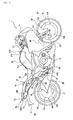
- Fig. 1 is a lateral view illustrating a basic configuration of a motorcycle according to the embodiment.
- Fig. 2 is a left lateral view of a vehicle body.
- a body frame 11 of a motorcycle 1 includes a head pipe 15, a pair of left and right main frames 17, a pair of left and right intermediate frames 19 and a pair of left and right seat rails 21.
- the head pipe 15 steerably supports a front fork 13.
- the main frames 17 extend from rearward downward from the head pipe 15.
- the intermediate frames 19 are provided continuously with the corresponding rear ends of both the main frames 17 so as to extend vertically.
- the seat rails 21 extend rearward upward from the corresponding upper portions of the intermediate frames 19.
- a front wheel 25 is rotatably supported by the lower end of the front fork 13.
- a handlebar 27 is coupled to an upper end of the front fork 13.
- a front fender 29 is supported by the front fork 13 so as to cover the front wheel 25 from above.
- Disk brakes 101 and 103 illustrated in Fig. 1 are mounted to the front wheel 25 and the rear wheel 47, respectively.
- the disk brake 101 for the front wheel 25 includes a brake disk 105 secured to and rotated integrally with the front wheel 25 and a caliper 107 mounted to the front fork 13.
- the caliper 107 incorporates a pair of left and right friction pads.
- the friction pads are moved toward and away from each other via a piston (not shown) by hydraulic pressure generated by a master cylinder (not shown).
- the friction pads hold under pressure braking surfaces 109 on both lateral surfaces of the brake disk 105 to apply a braking force to the front wheel 25.
- the friction pads hold under pressure braking surfaces 125 on both lateral surfaces of the brake disk 111 to apply a braking force to the rear wheel 47.
- a V-type water-cooled four-cylinder engine 31 is suspended by the main frames 17 and the intermediate frames 19 so as to be supported by a first support portion 700A, a second support portion 700B, a third support portion 700C and a fourth support portion 700D.
- Front cylinder exhaust pipes 35 extend forward from front cylinders 33 of the engine 31.
- Rear cylinder exhaust pipes 39 extend once rearward from the rear cylinders 37, then extending forward, and again extend rearward.
- the front cylinder exhaust pipes 35 and the rear cylinder exhaust pipes 39 extend downward along the front surface of a crankcase 41 of the engine 31, passing through a catalyst chamber (the CAT chamber) 43, and lie below the crankcase 41.
- the catalyst chamber 43 is connected via a collecting pipe described later to a rear collecting pipe 45.
- the rear collecting pipe 45 is disposed in a space defined between the lower portion of the crankcase 41 and the rear wheel 47 and connected to a muffler 49 extending on the vehicle body right side of the rear wheel 47.
- the rear collecting pipe 45 is supported below the crankcase 41.
- the muffler 49 is disposed to intersect the swing arm 53, as viewed from the side, which supports the rear wheel 47 at a rear end portion.
- the swing arm 53 is supported vertically swingably at its front end portion by means of a pivot shaft 55 so as to be located below the muffler 49 and suspended by a rear cushion 57 provided between an upper end portion of a pivot plate 51 and the swing arm 53.
- a step holder 407 equipped with a passenger step 403 is provided between the front wheel 25 and the rear wheel 47.
- the output power of the engine 31 is transmitted via a drive shaft 59 to the rear wheel 47.
- the drive shaft 59 is incorporated in the swing arm 53 disposed on the left side of the engine 31 in the state of facing the front Fr in the traveling direction of the motorcycle.
- a fuel tank 63 supported by the main frames 17 is disposed above the engine 31.
- a passenger seat (main seat) 65 used to sit a rider thereon is disposed behind the fuel tank 63 so as to be supported by the seat rails 21.
- a pillion seat 67 used to sit a pillion passenger thereon is disposed behind the main seat 65.
- a canister 201 is provided below the rear portion of the fuel tank 63 to capture vaporizing fuel gas in the fuel tank 63 without leakage.
- reference numeral 210 denotes a lid
- 212 denotes a fill opening
- 213 denotes a purge pipe.
- a radiator 69 is disposed in front of the engine 31.
- the head pipe 15 of the body frame 11 is covered from the front by a front cowl 71 made of synthetic resin.
- the front portion of the main frames 17, the radiator 69, and the front portion and lower portion of the engine 31 are covered from both sides by synthetic resin-made lower side cowls (not illustrated) continuous with the front cowl 71.
- a rear cowl 73 and a rear fender 75 are attached to the rear portion of the body frame 11.
- the rear cowl 73 covers the rear portion of the body frame 11.
- the rear fender 75 is disposed below the rear cowl 73 to cover the rear wheel 47 from above.
- a pair of left and right plate attachment portions 77 used to attach a license plate not shown thereto are provided on the rear fender 75.
- a rear combination lamp 79 is disposed in the rear cowl 73 so that its rear portion is faced to the rearward from the rear end of the rear cowl 73.
- the rear combination lamp 79 is an integral combination of a pair of left and right turn signal lamps 302 and a tail and stop lamp 304 located between the left and right turn signal lamps 302.
- reference numeral 81 denotes pillion step holders provided on the left and right of the vehicle body and 83 denotes a pillion step.
- Fig. 3 is a right lateral view of the vehicle in the vicinity of a step holder attachment portion.
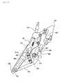
- Fig. 4 is a lateral view of a step holder assembly as viewed from the inside of the vehicle.
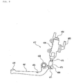
- Fig. 5 is a lateral view of a step holder as viewed from the inside of the vehicle.
- Fig. 6 is a cross-sectional view taken along line I-I of Fig. 4 .
- Fig. 7 is a cross-sectional view taken along line II-II of Fig. 4 .
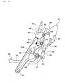
- Fig. 8 is a view for assistance in explaining operation encountered when a brake pedal is depressed.
- a step holder assembly 401 is provided between the front wheel 25 and rear wheel 47 of the motorcycle 1.
- the step holder assembly 401 is directly or indirectly attached to a body frame 11.
- the step holder assembly 401 includes a step holder 407 to which the passenger step 403 (see Fig. 14 ) and a rear brake pedal 405 are attached and a rear master cylinder 409 adapted to convert a tread force from the brake pedal 405 into brake pressure.
- the master cylinder 409 is attached to the step holder 407 via another stay (a master cylinder stay) 411 which is a stay member.
- the master cylinder stay 411 and the step holder 407 can be assembled temporarily and are co-fastened to the body frame 11.
- the step holder 407 is made by casting using a light alloy or the like.
- the step holder 407 is a general F-shaped plate material having a narrow lower portion and a wide upper portion.
- a brake pedal shaft 413 is provided by casting at a vertically, generally central portion of the step holder 407 so as to project toward the inside of the vehicle.
- the upper portion of the step holder 407 is formed with a master cylinder-exposed window 415.
- the central portion and lower portion of the step holder 407 are bored with co-fastening holes 419 and 421, respectively, used to co-fasten the step holder 407, the brake pedal-temporal assembly 417 and the like (see Fig. 9 ).
- a stop switch 423 is attached to the master cylinder stay 411.
- a braked pedal 405 is attached to the vehicle-widthwise inside of the step holder 407.
- a bearing portion 425 is provided at a rear portion of the brake pedal 405 so as to receive a brake pedal shaft 413 inserted through.
- a washer member 431 is provided on the vehicle-widthwise inside of the bearing portion 425 (see Fig. 11 ) of the brake pedal shaft 413.
- the washer member 431 includes an annular portion 427 adapted to receive brake pedal shaft 413 inserted therethrough and an arm portion 429 extending radially outwardly from the annular portion 427.
- One end of a stop switch spring 433 connected to the stop switch 423 is connected to the arm portion 429 of the washer member 431.
- the washer member 431 is integrally rotated with the brake pedal 405 with a retaining ring 435 or through nut-fastening.
- the master cylinder stay 411 is made of a material higher in strength than the brake pedal 405.
- the brake pedal 405 is made of a light alloy and the master cylinder stay 411 is made of high-tensile steel.
- the washer member 431 is integrally rotatably secured to the bearing portion 425 of the brake pedal 405 externally fitted to the brake pedal shaft 413.
- the rotation of the brake pedal 405 makes it possible to operate the stop switch 423 via the arm portion 429 of the washer member 431.
- the brake pedal shaft 413 is provided at an end with a circumferential groove portion 437 (see Fig. 14 ).
- a recessed portion 439 recessed radially inwardly is provided in a vehicle-widthwise internal lateral surface of the bearing portion 425 of the brake pedal 405.
- the washer member 431 further has a tongue portion 441 extending radially outwardly from the annular portion 427, bending vehicle-widthwise outwardly and engages the recessed portion 439.
- the retaining ring 435 is provided on the vehicle-widthwise inside of the washer member 431 so as to be engaged with the circumferential groove portion 437 of the brake pedal shaft 413.
- the step holder assembly 401 In the step holder assembly 401, the tongue portion 441 of the washer member 431 is engaged with the recessed portion 439 of the bearing portion 425 of the brake pedal 405 and becomes impossible to rotate relatively to each other.
- the step holder assembly 401 is configured to have a simple securing structure for integral rotation.
- the master cylinder 409 is attached to a rear upper portion of the master cylinder stay 411.
- a C-shaped stop switch stay 447 (see Fig. 6 ) is provided by welding at a portion, of the master cylinder stay 411, forward of the master cylinder 409 so as to engage the circumferential groove 445 (see Fig. 16 ) in the lateral surface of the stop switch 423.
- the stop switch 423 and the master cylinder 409 are arranged forward and rearward, respectively, of the brake pedal shaft 413 put therebetween. Therefore, the stop switch 423 is disposed at a position suited to obtain a pulling force from a pedal operating force. Thus, no waste spaces occur among the members, allowing for space-saving arrangement.
- the stop switch stay 447 has a C-shaped engagement ring portion 449 engaged with the circumferential groove portion 437 of the stop switch 423.
- the engaging ring portion 449 has an extending portion 451 extending radially outwardly therefrom.
- the master cylinder 409 is secured to the master cylinder stay 411 by means of a bolt 453 and a nut 455.
- a proximal end of the stop switch cover 457 is held between the master cylinder 409 and the nut 455.
- the stop switch cover 457 has a bending end side covering the outer circumference of the stop switch 423 to shield heat to the stop switch 423 from the exhaust pipe located vehicle-widthwise inwardly.
- a lateral wall of the stop switch cover 457 is bored with a hole portion 459 adapted to receive the extending portion 451.
- the stop switch cover 457 is provided on the vehicle-widthwise inside of the stop switch 423 so as to be engaged with the extending portion 451 and fastened to the stop switch stay 447.
- the stop switch cover 457 fastened to the stop switch stay 447 along with the master cylinder 409 is further engaged with the extending portion 451 of the stop switch stay 447 so as to be locked by the stop switch cover 457. This further ensures the heat shield and protection of the stop switch 423.
- An arm portion 461 of the brake pedal 405 is provided with a spring hook 463.
- a return spring 465 is spanned between the spring hook 463 and a spring hook 411A provided on the master cylinder stay 411.
- the arm portion 461 is depressed to turn the brake pedal 405 around the brake pedal shaft 413 counterclockwise. Thereafter, when the depression is released, the brake pedal 405 is turned clockwise by the restoring force of the return spring 465 and returned again to the position of Fig. 4 .
- reference numeral 471 denotes a retaining pin of the connecting shaft 473 inserted into the connecting portion 467 and the input portion 469.
- Reference numeral 475 denotes a stroke adjusting portion.
- Reference numeral 477 denotes a positioning hole of the master cylinder stay 411 engaged with a projecting portion 479 of the step holder 407.
- Reference numeral 481 denotes a co-fastening bolt passed through the step holder 407 and the master cylinder stay 411 shown in Fig. 7 and screwed to the body frame 11.
- Reference numeral 483 denotes a reservoir tank connection pipe of the master cylinder 409 and 484 denotes a brake line connecting portion.
- the master cylinder 409 is co-fastened to the step holder 407 via the master cylinder stay 411 and secured to the body frame 11. This enhances assembly performance.
- the composite structure in which the step holder 407 and the master cylinder stay 411 which are separate from each other are integrally co-fastened to each other can provide a vibration suppression effect. Even if the master cylinder 409 vibrates in arrow "a" directions or other directions, vibration can be made difficult to be transmitted to the step holder 407 compared with the configuration where the master cylinder 409 is fastened to the step holder 407.
- Fig. 9 is an explanatory view of an assembly procedure for assembling the brake pedal and the master cylinder.
- Fig. 10 is an explanatory view for a procedure for assembling the master cylinder stay.
- Fig. 11 is an explanatory view of an assembly procedure for assembling the step holder.
- Fig. 12 is an explanatory view of an assembly procedure for securing the master cylinder stay.
- Fig. 13 is a cross-sectional view taken along line III-III of Fig. 12 .
- the master cylinder 409 and the brake pedal 405 are temporarily assembled to each other by inserting the connecting shaft 473 into the connecting portion 467 and retaining it by means of the retaining pin 471.
- the master cylinder stay 411 is brought into a bolt insertion state with respect to the temporal assembly of the master cylinder 409 and the brake pedal 405. In this state, the nuts 455 are not yet fastened to the bolts 453, 453.
- the temporal assembly of the master cylinder 409, the brake pedal 405 and the master cylinder stay 411 illustrated in Fig. 10 is mounted to the step holder 407.
- the mounting is carried out by engaging the positioning hole 477 of the master cylinder stay 411 with the projecting portion 479 of the step holder 407 and inserting the bearing portion 425 of the brake pedal 405 to the brake pedal 413.
- a hexagon socket head screw 485 is fastened to secure the step holder 407 and the master cylinder stay 411 to each other.
- a gap 486 is defined between the master cylinder stay 411 and the step holder 407, thereby making it difficult for vibration to be transmitted.
- Fig. 14 is a perspective view of Fig. 12 as viewed from obliquely above.
- Fig. 15 is an explanatory view of an assembly procedure for assembling the stop switch.
- Fig. 16 is a lateral view of the stop switch assembly.
- Fig. 17 is an explanatory view of an assembly procedure for securing a pedal shaft washer.
- Fig. 18 is an explanatory view of an assembly procedure for assembling a stop switch cover.
- Fig. 19 is an explanatory view of an assembly procedure for co-fastening the master cylinder stay and the stop switch cover.
- Fig. 20 is an explanatory view of an assembly procedure for connection with a brake hose.
- the stop switch stay 447 is formed like a C-shape, it has a groove 487 capable of being increased in width vehicle-widthwise inwardly.
- the stop watch stay 447 is elastically deformed to make the stop switch 423 attachable thereto.
- the stop switch temporal-assembly 488 is mounted to the master cylinder stay 411.
- the stop switch temporal assembly 488 is one obtained by temporally assembling the stop switch 423, the stop switch spring 433 and the washer member 431.
- a small-diameter portion of the stop switch spring 433 is passed through the groove 487 formed in the engaging ring portion 449 of the stop switch stay 447 and moved downward to engage the circumferential groove 445 with the engaging ring portion 449.
- the washer member 431 fitted to the brake pedal shaft 413 is retained by the retaining ring 435.
- the stop switch cover 457 is passed through the bolt 453 and the hole portion 459 (see Fig. 6 ) is aligned with the extending portion 451.
- the bolts 453 are inserted into the master cylinder stay 411, the master cylinder 409 and the stop switch cover 457 and fastened with the nuts 455 for co-fastening.
- the return spring 465 is hooked on a lower support piece 489 of the master cylinder stay 411 and on the spring hook 463 of the brake pedal 405.
- a pipe 490 from a reservoir tank is coupled to the reservoir tank connection pipe 483 and a brake line pipe 491 is coupled to the brake line connecting portion 484, thus completing the assembly.
- Fig. 21 is a lateral view of the modification having a different stop switch operation structure. Incidentally, like reference numerals are attached to the same configurations as those used for the step holder assembly 401 and redundant explanations are omitted.
- a step holder assembly 401A according to the modification is such that the stop switch 423 is attached to a step holder 407A.
- the stop holder 407A is provided with a stop switch stay 447A.
- the proximal end of a link member 493 is swingably supported by the bolt 453.
- the link member 493 includes a stop switch connecting portion 493a and a link connecting portion 493b.
- the brake pedal 405 is provided with a link connecting arm 494.
- the link connecting portion 493b of the link member 493 is connected to the link connecting arm 494 of the brake pedal 405 by means of a connecting member 495.
- the connecting member 495 pulls the link connecting portion 493b of the link member 493 to turn the link member 493 clockwise, which pulls the stop switch 423 for operation. Since the stop switch 423 is directly secured to the stop holder 407, the master cylinder stay 411A can be downsized.
- the rear master cylinder 409 can temporarily be assembled to the stay 411 separate from the step holder 407 and they can be co-fastened to the body frame 11. Therefore, assembly performance is satisfactory.
- the step holder 407 will not resonate, so that the vibration of the step can be prevented.
- the pulling mechanism of the stop switch 423 can be provided in a compact manner.
- the washer 431 can be turned together with the pedal bearing 425 so that the pulling mechanism of the stop switch 423 can be provided in a compact manner.
- the length of the pedal shaft can be suppressed according to the shaft length of the nut compared with the structure of securing the washer 431 through nut-fastening. Since it is not necessary to provide a large seat surface for the nut at the pedal bearing portion, the rear brake application system can be made more compact.
- the brake application system can be made compact.
- the stay 411 can be attached in the state where the stop switch 423, the washer 431 and the stop switch spring 433 are temporarily assembled.
- the stop switch 423 can be protected by the small number of component parts.
- the flexibility of arrangement of the master cylinder 409 and the stop switch 423 can be increased by the provision of the link member 493.
- the invention is directed to provide a straddle-ride type vehicle that can prevent the resonance of a step holder to suppress the vibration of a step as much as possible while allowing for temporal assembly of a rear brake application system to a step holder.
- a straddle-ride type vehicle including a step holder 407 to which a passenger step and a brake pedal 405 are mounted, and a master cylinder 409 adapted to convert a tread force from the brake pedal 405 into brake pressure
- the master cylinder 409 is mounted to a stay 411 separate from the step holder 407, the stay 411 and the step holder 407 can temporarily be assembled to each other, and the step holder 407 and the stay 411 can be co-fastened to a body frame.
Landscapes
- Engineering & Computer Science (AREA)
- Mechanical Engineering (AREA)
- Transportation (AREA)
- Motorcycle And Bicycle Frame (AREA)
- Braking Elements And Transmission Devices (AREA)
Abstract
Description
- The present invention relates generally to a saddle-ride type vehicle and in particular to an improvement technology for a step holder attachment structure.
- In a conventional motorcycle which is a straddle-ride type vehicle, there is known a structure in which a rear master cylinder is attached to a step holder. If the master cylinder is previously attached to the step holder, it is possible to temporarily attach a step and a rear brake application system to the step holder, which facilitates assembly work.
- However, the motorcycle described in Patent Document
JP 2004-268774 A - The present invention has been made in view of the above-mentioned situations and aims to provide a straddle-ride type vehicle that can prevent the resonance of a step holder to suppress the vibration of a step as much as possible while allowing for temporal assembly of a rear brake application system to a step holder.
- To achieve the above object, the invention recited in
claim 1 is characterized in that in a straddle-ride type vehicle including: a step holder to which a passenger step and a brake pedal are mounted; and a master cylinder adapted to convert a tread force from the brake pedal into brake pressure; the master cylinder is mounted to a stay separate from the step holder, the stay and the step holder can temporarily be assembled to each other, and the step holder and the stay can be co-fastened to a body frame. - In the straddle-ride type vehicle, the master cylinder is co-fastened to the step holder via the stay to enhance assembly performance. In addition, even if the separate stay vibrates due to the composite configuration in which the separate members are integrally co-fastened to each other, the vibration of the step holder can be suppressed, that is, a vibration suppression effect can be provided.
- The invention recited in claim 2 is characterized in that, in addition to the configuration of the invention recited in
claim 1, a stop switch is attached to the stay, a brake pedal shaft is provided vehicle-widthwise inwardly of the step holder, a bearing portion adapted to receive the brake pedal shaft insertably passed therethrough is provided at a rear portion of the brake pedal, a washer member is provided vehicle-widthwise inwardly of the bearing portion of the brake pedal, the washer member having an annular portion is inserted into the brake pedal shaft and an arm portion extending radially outwardly from the annular portion, one end of a stop switch spring to be connected to the stop switch is connected to the arm portion of the washer member, and the washer member is turned together with the pedal through a retaining ring or nut-fastening. - In the straddle-ride type vehicle, the washer member is integrally-turnably secured to the bearing portion of the brake pedal externally inserted into the brake pedal shaft. Therefore, the turning of the brake pedal can operate the stop switch with a simple structure in which the arm portion of the washer member is mediated.
- The invention recited in claim 3 is characterized in that, in addition to the configuration of the invention recited in claim 2, the brake pedal shaft is provided with a circumferential groove portion at an end portion, a recessed portion is provided in a vehicle-widthwise inner lateral surface of the brake pedal bearing portion, the washer member further has a tongue portion extending radially outwardly from the annular portion and bending vehicle-widthwise outwardly, the retaining ring is provided vehicle-widthwise inwardly of the washer member so as to be engaged with the circumferential groove portion of the brake pedal shaft, and the tongue portion of the washer member is engaged with the recessed portion of the bearing portion of the brake pedal.
- In the straddle-ride vehicle, the washer member is engaged with the recessed portion of the bearing portion of the brake pedal through the tongue portion to become impossible to rotate with respect to each other. Thus, a securing structure for integral rotation is configured in a compact manner.
- The invention recited in claim 4 is characterized in that, in addition to the configuration of the invention recited in claim 2 or 3, the master cylinder is mounted to an upper rear portion of the stay, and a C-shaped stop switch stay is provided at the upper portion of the stay forwardly of the master cylinder so as to be engaged with a groove in a lateral surface of the stop switch.
- In the straddle-ride vehicle, the stop switch and the master cylinder are arranged forward and rearward, respectively, of the brake pedal shaft put therebetween. Therefore, the stop switch is disposed at a position suited to obtain a pulling force from a pedal operating force. Thus, no waste spaces occur among the members, thereby allowing for space-saving arrangement.
- The invention recited in claim 5 is characterized in that, in addition to the configuration of the invention recited in claim 4, the stop switch stay is partially formed with an extending portion extending radially outwardly of the C-shaped ring, and a stop switch cover engaged with the extending portion and fastened to the stay is provided vehicle-widthwise inwardly of the stop switch.
- In the saddle-ride vehicle, since the stop switch cover fastened to the stay is further engaged with the extending portion, the heat shield and protection of the stop switch can be ensured.
- The invention recited in claim 6 is characterized in that, in addition to the configuration of the invention recited in
claim 1, a stop switch is mounted to the step holder, a link member having a stop switch connecting portion and a link connecting portion is provided, the link member is pivotally supported by the stay, the brake pedal is provided with a link connecting arm, and a connecting member connected to a link connecting portion of the link member and to the link connecting arm of the brake pedal is provided. - In the straddle-ride vehicle, when the brake pedal is depressed, the connecting member pulls the link connecting portion of the link member to turn the link member, which pulls the stop switch for operation. Thus, the flexibility of arrangement of the master cylinder and the stop switch can be enhanced.
- According to the straddle-ride vehicle recited in
claim 1, the rear master cylinder can temporarily be assembled to the stay separate from the step holder and they are co-fastened to the body frame. Therefore, assembly performance is satisfactory. In addition, even if the stay resonates, the step holder will not resonate, thereby preventing the vibration of the step. - According to the straddle-ride vehicle recited in claim 2, the pulling mechanism of the stop switch can be provided in a compact manner.
- According to the straddle-ride vehicle recited in claim 3, the washer can be turned integrally with the bearing of the pedal; therefore, the pulling mechanism of the stop switch can be provided in a compact manner. The length of the pedal shaft can be suppressed according to the shaft length of the nut compared with the structure in which the washer is secured by nut-fastening. In addition, it is not necessary to provide a large seat surface for the nut on the bearing portion of the pedal; therefore, the rear bake application system can be made more compact.
- According to the straddle-ride vehicle recited in claim 4, the stop switch and the master cylinder are arranged forward and rearward, respectively, of the brake pedal shaft put therebetween. Therefore, the brake application system can be made compact and the stay can be attached in the state where the stop switch, the washer and the stop switch spring are temporarily assembled.
- According to the straddle-ride vehicle recited in claim 5, the stop switch can be shielded from heat and protected by the small number of component parts.
- According to the straddle-ride vehicle recited in claim 6, since the link member is provided, in addition to the effect of
claim 1, the flexibility of the arrangement of the master cylinder and the stop switch can be increased. -
-
Fig. 1 is a lateral view illustrating a basic configuration of a motorcycle according to an embodiment. -
Fig. 2 is a left lateral view of an essential portion of a vehicle body. -
Fig. 3 is a right lateral view of the vehicle in the vicinity of a step holder attachment portion. -
Fig. 4 is a lateral view of a step holder assembly as viewed from the inside of the vehicle. -
Fig. 5 is a lateral view of a step holder as viewed from the inside of the vehicle. -
Fig. 6 is a cross-sectional view taken along line I-I ofFig. 4 . -
Fig. 7 is a cross-sectional view taken along line II-II ofFig. 4 . -
Fig. 8 is a view for assistance in explaining operation encountered when a brake pedal is depressed. -
Fig. 9 is an explanatory view of an assembly procedure for assembling the brake pedal and a master cylinder. -
Fig. 10 is an explanatory view of an assembly procedure for assembling a master cylinder stay. -
Fig. 11 is an explanatory view of an assembly procedure for assembling a step holder. -
Fig. 12 is an explanatory view of an assembly procedure for securing a master cylinder stay. -
Fig. 13 is a cross-sectional view taken along line III-III ofFig. 12 . -
Fig. 14 is a perspective view ofFig. 12 as viewed from obliquely above. -
Fig. 15 is an explanatory view of an assembly procedure for assembling a stop switch. -
Fig. 16 is a lateral view of a stop switch assembly. -
Fig. 17 is an explanatory view of an assembly procedure for securing a pedal shaft washer. -
Fig. 18 is an explanatory view of an assembly procedure for assembling a stop switch cover. -
Fig. 19 is an explanatory view of an assembly procedure for co-fastening the master cylinder stay and the stop switch cover. -
Fig. 20 is an explanatory view of an assembly procedure for connecting a brake hose. -
Fig. 21 is a lateral view of a modification having a different stop switch operation structure. - One embodiment of a straddle-ride type vehicle according to the present invention will hereinafter be described in detail with reference to the drawings. It is to be noted that the drawings shall be viewed based on the direction of reference numerals. In the following description, the front and rear, left and right, and up and down are based on the direction a rider looks and the front, rear, left, right, upside and downside of the vehicle are denoted with symbols "Fr," "Rr," "L," "R," "U" and "D," respectively.
- The present invention can preferably be applied to e.g. motorcycles which are straddle-ride type vehicles.
-
Fig. 1 is a lateral view illustrating a basic configuration of a motorcycle according to the embodiment.Fig. 2 is a left lateral view of a vehicle body. - A
body frame 11 of amotorcycle 1 includes ahead pipe 15, a pair of left and rightmain frames 17, a pair of left and rightintermediate frames 19 and a pair of left and right seat rails 21. Thehead pipe 15 steerably supports afront fork 13. Themain frames 17 extend from rearward downward from thehead pipe 15. Theintermediate frames 19 are provided continuously with the corresponding rear ends of both themain frames 17 so as to extend vertically. The seat rails 21 extend rearward upward from the corresponding upper portions of the intermediate frames 19. - A
front wheel 25 is rotatably supported by the lower end of thefront fork 13. Ahandlebar 27 is coupled to an upper end of thefront fork 13. Afront fender 29 is supported by thefront fork 13 so as to cover thefront wheel 25 from above. -
Disk brakes Fig. 1 are mounted to thefront wheel 25 and therear wheel 47, respectively. For example, thedisk brake 101 for thefront wheel 25 includes abrake disk 105 secured to and rotated integrally with thefront wheel 25 and acaliper 107 mounted to thefront fork 13. Thecaliper 107 incorporates a pair of left and right friction pads. The friction pads are moved toward and away from each other via a piston (not shown) by hydraulic pressure generated by a master cylinder (not shown). The friction pads hold under pressure braking surfaces 109 on both lateral surfaces of thebrake disk 105 to apply a braking force to thefront wheel 25. Similarly, the friction pads hold under pressure braking surfaces 125 on both lateral surfaces of thebrake disk 111 to apply a braking force to therear wheel 47. - A V-type water-cooled four-
cylinder engine 31 is suspended by themain frames 17 and theintermediate frames 19 so as to be supported by afirst support portion 700A, asecond support portion 700B, athird support portion 700C and afourth support portion 700D. Frontcylinder exhaust pipes 35 extend forward fromfront cylinders 33 of theengine 31. Rearcylinder exhaust pipes 39 extend once rearward from therear cylinders 37, then extending forward, and again extend rearward. The frontcylinder exhaust pipes 35 and the rearcylinder exhaust pipes 39 extend downward along the front surface of acrankcase 41 of theengine 31, passing through a catalyst chamber (the CAT chamber) 43, and lie below thecrankcase 41. - The
catalyst chamber 43 is connected via a collecting pipe described later to arear collecting pipe 45. Therear collecting pipe 45 is disposed in a space defined between the lower portion of thecrankcase 41 and therear wheel 47 and connected to amuffler 49 extending on the vehicle body right side of therear wheel 47. Therear collecting pipe 45 is supported below thecrankcase 41. - The
muffler 49 is disposed to intersect theswing arm 53, as viewed from the side, which supports therear wheel 47 at a rear end portion. Theswing arm 53 is supported vertically swingably at its front end portion by means of apivot shaft 55 so as to be located below themuffler 49 and suspended by a rear cushion 57 provided between an upper end portion of a pivot plate 51 and theswing arm 53. Astep holder 407 equipped with apassenger step 403 is provided between thefront wheel 25 and therear wheel 47. - The output power of the
engine 31 is transmitted via adrive shaft 59 to therear wheel 47. Thedrive shaft 59 is incorporated in theswing arm 53 disposed on the left side of theengine 31 in the state of facing the front Fr in the traveling direction of the motorcycle. - A
fuel tank 63 supported by themain frames 17 is disposed above theengine 31. A passenger seat (main seat) 65 used to sit a rider thereon is disposed behind thefuel tank 63 so as to be supported by the seat rails 21. Apillion seat 67 used to sit a pillion passenger thereon is disposed behind themain seat 65. - A
canister 201 is provided below the rear portion of thefuel tank 63 to capture vaporizing fuel gas in thefuel tank 63 without leakage. InFig. 1 ,reference numeral 210 denotes a lid, 212 denotes a fill opening and 213 denotes a purge pipe. - A
radiator 69 is disposed in front of theengine 31. Thehead pipe 15 of thebody frame 11 is covered from the front by afront cowl 71 made of synthetic resin. The front portion of themain frames 17, theradiator 69, and the front portion and lower portion of theengine 31 are covered from both sides by synthetic resin-made lower side cowls (not illustrated) continuous with thefront cowl 71. - A
rear cowl 73 and arear fender 75 are attached to the rear portion of thebody frame 11. Therear cowl 73 covers the rear portion of thebody frame 11. Therear fender 75 is disposed below therear cowl 73 to cover therear wheel 47 from above. A pair of left and rightplate attachment portions 77 used to attach a license plate not shown thereto are provided on therear fender 75. - A
rear combination lamp 79 is disposed in therear cowl 73 so that its rear portion is faced to the rearward from the rear end of therear cowl 73. Therear combination lamp 79 is an integral combination of a pair of left and rightturn signal lamps 302 and a tail andstop lamp 304 located between the left and rightturn signal lamps 302. InFig. 1 ,reference numeral 81 denotes pillion step holders provided on the left and right of the vehicle body and 83 denotes a pillion step. -
Fig. 3 is a right lateral view of the vehicle in the vicinity of a step holder attachment portion.Fig. 4 is a lateral view of a step holder assembly as viewed from the inside of the vehicle.Fig. 5 is a lateral view of a step holder as viewed from the inside of the vehicle.Fig. 6 is a cross-sectional view taken along line I-I ofFig. 4 .Fig. 7 is a cross-sectional view taken along line II-II ofFig. 4 .Fig. 8 is a view for assistance in explaining operation encountered when a brake pedal is depressed. - A
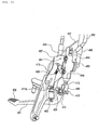
step holder assembly 401 is provided between thefront wheel 25 andrear wheel 47 of themotorcycle 1. Thestep holder assembly 401 is directly or indirectly attached to abody frame 11. Thestep holder assembly 401 includes astep holder 407 to which the passenger step 403 (seeFig. 14 ) and arear brake pedal 405 are attached and arear master cylinder 409 adapted to convert a tread force from thebrake pedal 405 into brake pressure. - The
master cylinder 409 is attached to thestep holder 407 via another stay (a master cylinder stay) 411 which is a stay member. Themaster cylinder stay 411 and thestep holder 407 can be assembled temporarily and are co-fastened to thebody frame 11. - Referring to
Fig. 5 , thestep holder 407 is made by casting using a light alloy or the like. Thestep holder 407 is a general F-shaped plate material having a narrow lower portion and a wide upper portion. Abrake pedal shaft 413 is provided by casting at a vertically, generally central portion of thestep holder 407 so as to project toward the inside of the vehicle. The upper portion of thestep holder 407 is formed with a master cylinder-exposedwindow 415. The central portion and lower portion of thestep holder 407 are bored withco-fastening holes step holder 407, the brake pedal-temporal assembly 417 and the like (seeFig. 9 ). - A
stop switch 423 is attached to themaster cylinder stay 411. Abraked pedal 405 is attached to the vehicle-widthwise inside of thestep holder 407. A bearingportion 425 is provided at a rear portion of thebrake pedal 405 so as to receive abrake pedal shaft 413 inserted through. Awasher member 431 is provided on the vehicle-widthwise inside of the bearing portion 425 (seeFig. 11 ) of thebrake pedal shaft 413. Thewasher member 431 includes anannular portion 427 adapted to receivebrake pedal shaft 413 inserted therethrough and anarm portion 429 extending radially outwardly from theannular portion 427. One end of astop switch spring 433 connected to thestop switch 423 is connected to thearm portion 429 of thewasher member 431. Thewasher member 431 is integrally rotated with thebrake pedal 405 with a retainingring 435 or through nut-fastening. - Incidentally, the
master cylinder stay 411 is made of a material higher in strength than thebrake pedal 405. For example, in the present embodiment, thebrake pedal 405 is made of a light alloy and themaster cylinder stay 411 is made of high-tensile steel. - In the
step holder assembly 401, thewasher member 431 is integrally rotatably secured to the bearingportion 425 of thebrake pedal 405 externally fitted to thebrake pedal shaft 413. Thus, the rotation of thebrake pedal 405 makes it possible to operate thestop switch 423 via thearm portion 429 of thewasher member 431. - The
brake pedal shaft 413 is provided at an end with a circumferential groove portion 437 (seeFig. 14 ). A recessedportion 439 recessed radially inwardly is provided in a vehicle-widthwise internal lateral surface of the bearingportion 425 of thebrake pedal 405. Thewasher member 431 further has atongue portion 441 extending radially outwardly from theannular portion 427, bending vehicle-widthwise outwardly and engages the recessedportion 439. The retainingring 435 is provided on the vehicle-widthwise inside of thewasher member 431 so as to be engaged with thecircumferential groove portion 437 of thebrake pedal shaft 413. - In the
step holder assembly 401, thetongue portion 441 of thewasher member 431 is engaged with the recessedportion 439 of the bearingportion 425 of thebrake pedal 405 and becomes impossible to rotate relatively to each other. In short, thestep holder assembly 401 is configured to have a simple securing structure for integral rotation. - The
master cylinder 409 is attached to a rear upper portion of themaster cylinder stay 411. A C-shaped stop switch stay 447 (seeFig. 6 ) is provided by welding at a portion, of themaster cylinder stay 411, forward of themaster cylinder 409 so as to engage the circumferential groove 445 (seeFig. 16 ) in the lateral surface of thestop switch 423. - In the
step holder assembly 401, thestop switch 423 and themaster cylinder 409 are arranged forward and rearward, respectively, of thebrake pedal shaft 413 put therebetween. Therefore, thestop switch 423 is disposed at a position suited to obtain a pulling force from a pedal operating force. Thus, no waste spaces occur among the members, allowing for space-saving arrangement. - As illustrated in
Fig. 6 , thestop switch stay 447 has a C-shapedengagement ring portion 449 engaged with thecircumferential groove portion 437 of thestop switch 423. The engagingring portion 449 has an extendingportion 451 extending radially outwardly therefrom. Themaster cylinder 409 is secured to themaster cylinder stay 411 by means of abolt 453 and anut 455. A proximal end of thestop switch cover 457 is held between themaster cylinder 409 and thenut 455. Thestop switch cover 457 has a bending end side covering the outer circumference of thestop switch 423 to shield heat to thestop switch 423 from the exhaust pipe located vehicle-widthwise inwardly. A lateral wall of thestop switch cover 457 is bored with ahole portion 459 adapted to receive the extendingportion 451. Thestop switch cover 457 is provided on the vehicle-widthwise inside of thestop switch 423 so as to be engaged with the extendingportion 451 and fastened to thestop switch stay 447. - The
stop switch cover 457 fastened to the stop switch stay 447 along with themaster cylinder 409 is further engaged with the extendingportion 451 of the stop switch stay 447 so as to be locked by thestop switch cover 457. This further ensures the heat shield and protection of thestop switch 423. - An
arm portion 461 of thebrake pedal 405 is provided with aspring hook 463. Areturn spring 465 is spanned between thespring hook 463 and aspring hook 411A provided on themaster cylinder stay 411. As illustrated inFig. 8 , thearm portion 461 is depressed to turn thebrake pedal 405 around thebrake pedal shaft 413 counterclockwise. Thereafter, when the depression is released, thebrake pedal 405 is turned clockwise by the restoring force of thereturn spring 465 and returned again to the position ofFig. 4 . - When the
brake pedal shaft 413 is depressed to turn thearm portion 429, thestop switch 423 is operatively pulled via thestop switch spring 433. A connectingportion 467, of thebrake pedal 405, on the side opposite thearm portion 461 with thebrake pedal shaft 413 put therebetween presses aninput portion 469 of themaster cylinder 409. - Incidentally, in the figures,
reference numeral 471 denotes a retaining pin of the connectingshaft 473 inserted into the connectingportion 467 and theinput portion 469.Reference numeral 475 denotes a stroke adjusting portion.Reference numeral 477 denotes a positioning hole of themaster cylinder stay 411 engaged with a projectingportion 479 of thestep holder 407.Reference numeral 481 denotes a co-fastening bolt passed through thestep holder 407 and themaster cylinder stay 411 shown inFig. 7 and screwed to thebody frame 11.Reference numeral 483 denotes a reservoir tank connection pipe of themaster cylinder - According to the
step holder assembly 401 configured as above, as illustrated inFig. 7 , themaster cylinder 409 is co-fastened to thestep holder 407 via themaster cylinder stay 411 and secured to thebody frame 11. This enhances assembly performance. The composite structure in which thestep holder 407 and themaster cylinder stay 411 which are separate from each other are integrally co-fastened to each other can provide a vibration suppression effect. Even if themaster cylinder 409 vibrates in arrow "a" directions or other directions, vibration can be made difficult to be transmitted to thestep holder 407 compared with the configuration where themaster cylinder 409 is fastened to thestep holder 407. - Next, a description is given of a procedure for assembling the
step holder assembly 401. -
Fig. 9 is an explanatory view of an assembly procedure for assembling the brake pedal and the master cylinder.Fig. 10 is an explanatory view for a procedure for assembling the master cylinder stay.Fig. 11 is an explanatory view of an assembly procedure for assembling the step holder.Fig. 12 is an explanatory view of an assembly procedure for securing the master cylinder stay.Fig. 13 is a cross-sectional view taken along line III-III ofFig. 12 . - As illustrated in
Fig. 9 , first, themaster cylinder 409 and thebrake pedal 405 are temporarily assembled to each other by inserting the connectingshaft 473 into the connectingportion 467 and retaining it by means of the retainingpin 471. As illustrated inFig. 10 , themaster cylinder stay 411 is brought into a bolt insertion state with respect to the temporal assembly of themaster cylinder 409 and thebrake pedal 405. In this state, thenuts 455 are not yet fastened to thebolts - As illustrated in
Fig. 11 , the temporal assembly of themaster cylinder 409, thebrake pedal 405 and themaster cylinder stay 411 illustrated inFig. 10 is mounted to thestep holder 407. The mounting is carried out by engaging thepositioning hole 477 of themaster cylinder stay 411 with the projectingportion 479 of thestep holder 407 and inserting the bearingportion 425 of thebrake pedal 405 to thebrake pedal 413. In the state as illustrated inFig. 12 , a hexagonsocket head screw 485 is fastened to secure thestep holder 407 and themaster cylinder stay 411 to each other. - As illustrated in
Fig. 13 , in the state where the hexagonsocket head screw 485 is fastened up, agap 486 is defined between themaster cylinder stay 411 and thestep holder 407, thereby making it difficult for vibration to be transmitted. -
Fig. 14 is a perspective view ofFig. 12 as viewed from obliquely above.Fig. 15 is an explanatory view of an assembly procedure for assembling the stop switch.Fig. 16 is a lateral view of the stop switch assembly.Fig. 17 is an explanatory view of an assembly procedure for securing a pedal shaft washer.Fig. 18 is an explanatory view of an assembly procedure for assembling a stop switch cover.Fig. 19 is an explanatory view of an assembly procedure for co-fastening the master cylinder stay and the stop switch cover.Fig. 20 is an explanatory view of an assembly procedure for connection with a brake hose. - As illustrated in
Fig. 14 , since thestop switch stay 447 is formed like a C-shape, it has agroove 487 capable of being increased in width vehicle-widthwise inwardly. Thus, the stop watchstay 447 is elastically deformed to make thestop switch 423 attachable thereto. - As illustrated in
Fig. 15 , the stop switch temporal-assembly 488 is mounted to themaster cylinder stay 411. As illustrated inFig. 16 , the stop switchtemporal assembly 488 is one obtained by temporally assembling thestop switch 423, thestop switch spring 433 and thewasher member 431. In thestop switch 423, a small-diameter portion of thestop switch spring 433 is passed through thegroove 487 formed in theengaging ring portion 449 of the stop switch stay 447 and moved downward to engage thecircumferential groove 445 with the engagingring portion 449. - As illustrated in
Fig. 17 , thewasher member 431 fitted to thebrake pedal shaft 413 is retained by the retainingring 435. As illustrated inFig. 18 , thestop switch cover 457 is passed through thebolt 453 and the hole portion 459 (seeFig. 6 ) is aligned with the extendingportion 451. In this state, as illustrated inFig. 19 , thebolts 453 are inserted into themaster cylinder stay 411, themaster cylinder 409 and thestop switch cover 457 and fastened with thenuts 455 for co-fastening. - As illustrated in
Fig. 20 , thereturn spring 465 is hooked on a lower support piece 489 of themaster cylinder stay 411 and on thespring hook 463 of thebrake pedal 405. Lastly, apipe 490 from a reservoir tank is coupled to the reservoirtank connection pipe 483 and abrake line pipe 491 is coupled to the brakeline connecting portion 484, thus completing the assembly. - A description is next given of a modification of the
step holder assembly 401. -
Fig. 21 is a lateral view of the modification having a different stop switch operation structure. Incidentally, like reference numerals are attached to the same configurations as those used for thestep holder assembly 401 and redundant explanations are omitted. - A
step holder assembly 401A according to the modification is such that thestop switch 423 is attached to astep holder 407A. Thestop holder 407A is provided with a stop switch stay 447A. The proximal end of alink member 493 is swingably supported by thebolt 453. Thelink member 493 includes a stopswitch connecting portion 493a and alink connecting portion 493b. Thebrake pedal 405 is provided with alink connecting arm 494. Thelink connecting portion 493b of thelink member 493 is connected to thelink connecting arm 494 of thebrake pedal 405 by means of a connectingmember 495. - With the
step holder assembly 401A according to the modification, if thebrake pedal 405 is depressed, the connectingmember 495 pulls thelink connecting portion 493b of thelink member 493 to turn thelink member 493 clockwise, which pulls thestop switch 423 for operation. Since thestop switch 423 is directly secured to thestop holder 407, themaster cylinder stay 411A can be downsized. - As described above, according to the motorcycle of the present embodiment, the
rear master cylinder 409 can temporarily be assembled to thestay 411 separate from thestep holder 407 and they can be co-fastened to thebody frame 11. Therefore, assembly performance is satisfactory. In addition, even if thestay 411 resonates, thestep holder 407 will not resonate, so that the vibration of the step can be prevented. - According to the motorcycle of the present embodiment, the pulling mechanism of the
stop switch 423 can be provided in a compact manner. - According to the motorcycle of the present embodiment, the
washer 431 can be turned together with the pedal bearing 425 so that the pulling mechanism of thestop switch 423 can be provided in a compact manner. The length of the pedal shaft can be suppressed according to the shaft length of the nut compared with the structure of securing thewasher 431 through nut-fastening. Since it is not necessary to provide a large seat surface for the nut at the pedal bearing portion, the rear brake application system can be made more compact. - According to the motorcycle of the present embodiment, since the
stop switch 423 is located anteriorly and themaster cylinder 409 posteriorly, the brake application system can be made compact. In addition, thestay 411 can be attached in the state where thestop switch 423, thewasher 431 and thestop switch spring 433 are temporarily assembled. - According to the motorcycle of the present embodiment, the
stop switch 423 can be protected by the small number of component parts. - According to the motorcycle of the present embodiment, in addition to the effect of
claim 1, the flexibility of arrangement of themaster cylinder 409 and thestop switch 423 can be increased by the provision of thelink member 493. - The invention is directed to provide a straddle-ride type vehicle that can prevent the resonance of a step holder to suppress the vibration of a step as much as possible while allowing for temporal assembly of a rear brake application system to a step holder.
- In a straddle-ride type vehicle including a
step holder 407 to which a passenger step and abrake pedal 405 are mounted, and amaster cylinder 409 adapted to convert a tread force from thebrake pedal 405 into brake pressure, themaster cylinder 409 is mounted to astay 411 separate from thestep holder 407, thestay 411 and thestep holder 407 can temporarily be assembled to each other, and thestep holder 407 and thestay 411 can be co-fastened to a body frame.
Claims (6)
- A straddle-ride type vehicle (1) comprising:a step holder (407) to which a passenger step (403) and a brake pedal (405) are mounted; anda master cylinder (409) adapted to convert a tread force from the brake pedal (405) into brake pressure;wherein the master cylinder (409) is mounted to a stay separate from the step holder (407),the stay and the step holder (407) can temporarily be assembled to each other, andthe step holder (407) and the stay can be co-fastened to a body frame (11).
- The straddle-ride type vehicle (1) according to claim 1,
wherein a stop switch (423) is attached to the stay,
a brake pedal shaft (413) is provided vehicle-widthwise inwardly of the step holder (407),
a bearing portion (425) adapted to receive the brake pedal shaft (413) insertably passed therethrough is provided at a rear portion of the brake pedal (405),
a washer member (431) is provided vehicle-widthwise inwardly of the bearing portion (425) of the brake pedal (405), the washer member (431) having an annular portion (427) inserted into the brake pedal shaft (413) and an arm portion (429) extending radially outwardly from the annular portion (427),
one end of a stop switch spring to be connected to the stop switch (423) is connected to the arm portion (429) of the washer member (431), and
the washer member (431) is rotated together with the pedal (405) through a retaining ring (435) or nut-fastening. - The straddle-type vehicle (1) according to claim 2,
wherein the brake pedal shaft (413) is provided with a circumferential groove portion (437) at an end portion,
a recessed portion (439) is provided in a vehicle-widthwise inner lateral surface of the brake pedal bearing portion (425),
the washer member (431) further has a tongue portion (441) extending radially outwardly from the annular portion (427) and bending vehicle-widthwise outwardly,
the retaining ring (435) is provided vehicle-widthwise inwardly of the washer member (431) so as to be engaged with the circumferential groove portion (437) of the brake pedal shaft (413), and
the tongue portion (441) of the washer member (431) is engaged with the recessed portion (439) of the bearing portion (425) of the brake pedal (405). - The saddle-ride type vehicle (1) according to claim 2 or 3,
wherein the master cylinder (409) is mounted to an upper rear portion of the stay, and
a C-shaped stop switch stay (447) is provided at the upper portion of the stay forwardly of the master cylinder (409) so as to be engaged with a groove (445) in a lateral surface of the stop switch (423). - The saddle-ride type vehicle according to claim 4,
wherein the stop switch stay (447) is partially formed with an extending portion (451) extending radially outwardly of the C-shaped ring, and
a stop switch cover (457) engaged with the extending portion (451) and fastened to the stay is provided vehicle-widthwise inwardly of the stop switch (423). - The straddle-ride vehicle (1) according to claim 1,
wherein a stop switch (423) is mounted to the step holder (407), a link member (493) having a stop switch connecting portion (493a) and a link connecting portion (493b) is provided,
the link member (493) is pivotally supported by the stay,
the brake pedal (405) is provided with a link connecting arm (494), and
a connecting member (495) connected to a link connecting portion (493b) of the link member (493) and to the link connecting arm (494) of the brake pedal (405) is provided.
Applications Claiming Priority (1)
| Application Number | Priority Date | Filing Date | Title |
|---|---|---|---|
| JP2009087774A JP5261825B2 (en) | 2009-03-31 | 2009-03-31 | Saddle riding |
Publications (2)
| Publication Number | Publication Date |
|---|---|
| EP2236399A1 true EP2236399A1 (en) | 2010-10-06 |
| EP2236399B1 EP2236399B1 (en) | 2012-06-20 |
Family
ID=42103031
Family Applications (1)
| Application Number | Title | Priority Date | Filing Date |
|---|---|---|---|
| EP10154248A Not-in-force EP2236399B1 (en) | 2009-03-31 | 2010-02-22 | Straddle-ride type vehicle |
Country Status (3)
| Country | Link |
|---|---|
| US (1) | US8235157B2 (en) |
| EP (1) | EP2236399B1 (en) |
| JP (1) | JP5261825B2 (en) |
Cited By (1)
| Publication number | Priority date | Publication date | Assignee | Title |
|---|---|---|---|---|
| CN102556023A (en) * | 2010-12-08 | 2012-07-11 | 本田技研工业株式会社 | Brake device for motorcycle |
Families Citing this family (7)
| Publication number | Priority date | Publication date | Assignee | Title |
|---|---|---|---|---|
| JP3165481U (en) * | 2008-03-07 | 2011-01-27 | ヤマハ発動機株式会社 | Saddle riding vehicle |
| CN102050097A (en) * | 2010-12-30 | 2011-05-11 | 翁光敏 | Hydraulic mechanism of motorcycle rear disc brake |
| JP5760513B2 (en) * | 2011-03-01 | 2015-08-12 | スズキ株式会社 | Saddle riding vehicle |
| JP5887241B2 (en) * | 2012-09-27 | 2016-03-16 | 本田技研工業株式会社 | Interlocking brake device for motorcycles |
| JP5887240B2 (en) * | 2012-09-27 | 2016-03-16 | 本田技研工業株式会社 | Interlocking brake device for motorcycles |
| JP6825394B2 (en) * | 2017-02-01 | 2021-02-03 | スズキ株式会社 | Master cylinder device for rear wheel brakes of motorcycles and master cylinder arrangement method for rear wheel brakes of motorcycles |
| CA3175338A1 (en) * | 2022-09-22 | 2022-12-15 | Cory L. Hanson | Yamaha tenere 700 rear brake pedal |
Citations (4)
| Publication number | Priority date | Publication date | Assignee | Title |
|---|---|---|---|---|
| JPS559749U (en) * | 1978-07-04 | 1980-01-22 | ||
| JP2004268774A (en) | 2003-03-10 | 2004-09-30 | Honda Motor Co Ltd | Motorcycle step structure |
| EP1908678A2 (en) * | 2006-10-06 | 2008-04-09 | Yamaha Hatsudoki Kabushiki Kaisha | Motorcycle |
| US20090058030A1 (en) * | 2007-08-30 | 2009-03-05 | Honda Motor Co., Ltd. | Arrangement structure of a rear master cylinder and a hydraulic fluid reservoir tank in a saddle-riding type vehicle, and motorcycle incorporating same |
Family Cites Families (10)
| Publication number | Priority date | Publication date | Assignee | Title |
|---|---|---|---|---|
| JPS5311943Y2 (en) * | 1975-06-17 | 1978-03-31 | ||
| JPS59129690U (en) * | 1983-02-22 | 1984-08-31 | スズキ株式会社 | Motorcycle rear brake device |
| JPH064436B2 (en) * | 1985-01-08 | 1994-01-19 | ヤマハ発動機株式会社 | Brake operation device for motorcycles |
| JPH042156Y2 (en) * | 1986-10-24 | 1992-01-24 | ||
| DE9202600U1 (en) * | 1992-02-28 | 1992-04-23 | Motorrad Müller GmbH, 8898 Schrobenhausen | Footrest holder for motorcycles |
| JP4118542B2 (en) * | 2001-09-17 | 2008-07-16 | 本田技研工業株式会社 | Step device |
| US6688628B2 (en) * | 2001-10-17 | 2004-02-10 | Robert C. Burkett | Motorcycle bracket |
| JP4108513B2 (en) * | 2003-03-19 | 2008-06-25 | 本田技研工業株式会社 | Wheel structure and wheel assembling method |
| JP2008056140A (en) * | 2006-08-31 | 2008-03-13 | Honda Motor Co Ltd | Motorcycle |
| US20110020060A1 (en) * | 2009-07-23 | 2011-01-27 | Mon Spencer Owyang | Reversible attachment apparatus for a footpeg assembly |
-
2009
- 2009-03-31 JP JP2009087774A patent/JP5261825B2/en not_active Expired - Fee Related
-
2010
- 2010-02-22 EP EP10154248A patent/EP2236399B1/en not_active Not-in-force
- 2010-03-04 US US12/717,490 patent/US8235157B2/en not_active Expired - Fee Related
Patent Citations (4)
| Publication number | Priority date | Publication date | Assignee | Title |
|---|---|---|---|---|
| JPS559749U (en) * | 1978-07-04 | 1980-01-22 | ||
| JP2004268774A (en) | 2003-03-10 | 2004-09-30 | Honda Motor Co Ltd | Motorcycle step structure |
| EP1908678A2 (en) * | 2006-10-06 | 2008-04-09 | Yamaha Hatsudoki Kabushiki Kaisha | Motorcycle |
| US20090058030A1 (en) * | 2007-08-30 | 2009-03-05 | Honda Motor Co., Ltd. | Arrangement structure of a rear master cylinder and a hydraulic fluid reservoir tank in a saddle-riding type vehicle, and motorcycle incorporating same |
Cited By (2)
| Publication number | Priority date | Publication date | Assignee | Title |
|---|---|---|---|---|
| CN102556023A (en) * | 2010-12-08 | 2012-07-11 | 本田技研工业株式会社 | Brake device for motorcycle |
| CN102556023B (en) * | 2010-12-08 | 2015-02-25 | 本田技研工业株式会社 | Brake device for motorcycle |
Also Published As
| Publication number | Publication date |
|---|---|
| JP5261825B2 (en) | 2013-08-14 |
| JP2010235052A (en) | 2010-10-21 |
| US20100243359A1 (en) | 2010-09-30 |
| US8235157B2 (en) | 2012-08-07 |
| EP2236399B1 (en) | 2012-06-20 |
Similar Documents
| Publication | Publication Date | Title |
|---|---|---|
| EP2236399B1 (en) | Straddle-ride type vehicle | |
| JP5261827B2 (en) | Canister mounting structure for saddle-ride type vehicles | |
| JP5239087B2 (en) | Saddle riding | |
| US7661502B2 (en) | Parking brake system | |
| WO2011114631A1 (en) | Brake device for saddled vehicle | |
| US20090242304A1 (en) | Motorcycle with control unit for controlling operation of a brake pressure regulating unit | |
| US8381863B2 (en) | Connection structure arrangement between a frame member and an engine of a saddle-type vehicle, and vehicle incorporating same | |
| US10494047B2 (en) | Saddle-riding-type vehicle cable support structure | |
| US7621566B2 (en) | Brake hose support structure | |
| US10780936B2 (en) | Straddle-type vehicle | |
| JP2019081518A (en) | Saddle riding type vehicle | |
| JP5414330B2 (en) | Saddle riding | |
| JP2009090892A (en) | Saddle riding vehicle | |
| JP6832821B2 (en) | Component support structure for saddle-mounted vehicles | |
| JP7253627B2 (en) | Wheel speed sensor mounting structure for saddle type vehicle | |
| JP7712814B2 (en) | Meter bracket for straddle-type vehicles | |
| JP2013181652A (en) | Spacer | |
| JP2006096215A (en) | Chain guide device | |
| JP2004338428A (en) | Saddle-type vehicle fender | |
| JP2023047986A (en) | Motion mechanism |
Legal Events
| Date | Code | Title | Description |
|---|---|---|---|
| PUAI | Public reference made under article 153(3) epc to a published international application that has entered the european phase |
Free format text: ORIGINAL CODE: 0009012 |
|
| 17P | Request for examination filed |
Effective date: 20100222 |
|
| AK | Designated contracting states |
Kind code of ref document: A1 Designated state(s): AT BE BG CH CY CZ DE DK EE ES FI FR GB GR HR HU IE IS IT LI LT LU LV MC MK MT NL NO PL PT RO SE SI SK SM TR |
|
| RIC1 | Information provided on ipc code assigned before grant |
Ipc: B62K 19/38 20060101ALI20110405BHEP Ipc: B62K 23/08 20060101ALI20110405BHEP Ipc: B62J 25/00 20060101AFI20110405BHEP Ipc: B62L 3/02 20060101ALI20110405BHEP |
|
| 17Q | First examination report despatched |
Effective date: 20110523 |
|
| GRAP | Despatch of communication of intention to grant a patent |
Free format text: ORIGINAL CODE: EPIDOSNIGR1 |
|
| GRAS | Grant fee paid |
Free format text: ORIGINAL CODE: EPIDOSNIGR3 |
|
| GRAA | (expected) grant |
Free format text: ORIGINAL CODE: 0009210 |
|
| AK | Designated contracting states |
Kind code of ref document: B1 Designated state(s): AT BE BG CH CY CZ DE DK EE ES FI FR GB GR HR HU IE IS IT LI LT LU LV MC MK MT NL NO PL PT RO SE SI SK SM TR |
|
| REG | Reference to a national code |
Ref country code: GB Ref legal event code: FG4D |
|
| REG | Reference to a national code |
Ref country code: CH Ref legal event code: EP |
|
| REG | Reference to a national code |
Ref country code: AT Ref legal event code: REF Ref document number: 562907 Country of ref document: AT Kind code of ref document: T Effective date: 20120715 |
|
| REG | Reference to a national code |
Ref country code: IE Ref legal event code: FG4D |
|
| REG | Reference to a national code |
Ref country code: DE Ref legal event code: R096 Ref document number: 602010001885 Country of ref document: DE Effective date: 20120816 |
|
| PG25 | Lapsed in a contracting state [announced via postgrant information from national office to epo] |
Ref country code: LT Free format text: LAPSE BECAUSE OF FAILURE TO SUBMIT A TRANSLATION OF THE DESCRIPTION OR TO PAY THE FEE WITHIN THE PRESCRIBED TIME-LIMIT Effective date: 20120620 Ref country code: SE Free format text: LAPSE BECAUSE OF FAILURE TO SUBMIT A TRANSLATION OF THE DESCRIPTION OR TO PAY THE FEE WITHIN THE PRESCRIBED TIME-LIMIT Effective date: 20120620 Ref country code: NO Free format text: LAPSE BECAUSE OF FAILURE TO SUBMIT A TRANSLATION OF THE DESCRIPTION OR TO PAY THE FEE WITHIN THE PRESCRIBED TIME-LIMIT Effective date: 20120920 Ref country code: FI Free format text: LAPSE BECAUSE OF FAILURE TO SUBMIT A TRANSLATION OF THE DESCRIPTION OR TO PAY THE FEE WITHIN THE PRESCRIBED TIME-LIMIT Effective date: 20120620 |
|
| REG | Reference to a national code |
Ref country code: NL Ref legal event code: VDEP Effective date: 20120620 |
|
| REG | Reference to a national code |
Ref country code: AT Ref legal event code: MK05 Ref document number: 562907 Country of ref document: AT Kind code of ref document: T Effective date: 20120620 |
|
| REG | Reference to a national code |
Ref country code: LT Ref legal event code: MG4D Effective date: 20120620 |
|
| PG25 | Lapsed in a contracting state [announced via postgrant information from national office to epo] |
Ref country code: GR Free format text: LAPSE BECAUSE OF FAILURE TO SUBMIT A TRANSLATION OF THE DESCRIPTION OR TO PAY THE FEE WITHIN THE PRESCRIBED TIME-LIMIT Effective date: 20120921 Ref country code: LV Free format text: LAPSE BECAUSE OF FAILURE TO SUBMIT A TRANSLATION OF THE DESCRIPTION OR TO PAY THE FEE WITHIN THE PRESCRIBED TIME-LIMIT Effective date: 20120620 Ref country code: HR Free format text: LAPSE BECAUSE OF FAILURE TO SUBMIT A TRANSLATION OF THE DESCRIPTION OR TO PAY THE FEE WITHIN THE PRESCRIBED TIME-LIMIT Effective date: 20120620 Ref country code: SI Free format text: LAPSE BECAUSE OF FAILURE TO SUBMIT A TRANSLATION OF THE DESCRIPTION OR TO PAY THE FEE WITHIN THE PRESCRIBED TIME-LIMIT Effective date: 20120620 |
|
| PG25 | Lapsed in a contracting state [announced via postgrant information from national office to epo] |
Ref country code: AT Free format text: LAPSE BECAUSE OF FAILURE TO SUBMIT A TRANSLATION OF THE DESCRIPTION OR TO PAY THE FEE WITHIN THE PRESCRIBED TIME-LIMIT Effective date: 20120620 Ref country code: SK Free format text: LAPSE BECAUSE OF FAILURE TO SUBMIT A TRANSLATION OF THE DESCRIPTION OR TO PAY THE FEE WITHIN THE PRESCRIBED TIME-LIMIT Effective date: 20120620 Ref country code: IS Free format text: LAPSE BECAUSE OF FAILURE TO SUBMIT A TRANSLATION OF THE DESCRIPTION OR TO PAY THE FEE WITHIN THE PRESCRIBED TIME-LIMIT Effective date: 20121020 Ref country code: RO Free format text: LAPSE BECAUSE OF FAILURE TO SUBMIT A TRANSLATION OF THE DESCRIPTION OR TO PAY THE FEE WITHIN THE PRESCRIBED TIME-LIMIT Effective date: 20120620 Ref country code: CY Free format text: LAPSE BECAUSE OF FAILURE TO SUBMIT A TRANSLATION OF THE DESCRIPTION OR TO PAY THE FEE WITHIN THE PRESCRIBED TIME-LIMIT Effective date: 20120620 Ref country code: BE Free format text: LAPSE BECAUSE OF FAILURE TO SUBMIT A TRANSLATION OF THE DESCRIPTION OR TO PAY THE FEE WITHIN THE PRESCRIBED TIME-LIMIT Effective date: 20120620 Ref country code: CZ Free format text: LAPSE BECAUSE OF FAILURE TO SUBMIT A TRANSLATION OF THE DESCRIPTION OR TO PAY THE FEE WITHIN THE PRESCRIBED TIME-LIMIT Effective date: 20120620 Ref country code: EE Free format text: LAPSE BECAUSE OF FAILURE TO SUBMIT A TRANSLATION OF THE DESCRIPTION OR TO PAY THE FEE WITHIN THE PRESCRIBED TIME-LIMIT Effective date: 20120620 |
|
| PG25 | Lapsed in a contracting state [announced via postgrant information from national office to epo] |
Ref country code: PL Free format text: LAPSE BECAUSE OF FAILURE TO SUBMIT A TRANSLATION OF THE DESCRIPTION OR TO PAY THE FEE WITHIN THE PRESCRIBED TIME-LIMIT Effective date: 20120620 Ref country code: PT Free format text: LAPSE BECAUSE OF FAILURE TO SUBMIT A TRANSLATION OF THE DESCRIPTION OR TO PAY THE FEE WITHIN THE PRESCRIBED TIME-LIMIT Effective date: 20121022 |
|
| PG25 | Lapsed in a contracting state [announced via postgrant information from national office to epo] |
Ref country code: NL Free format text: LAPSE BECAUSE OF FAILURE TO SUBMIT A TRANSLATION OF THE DESCRIPTION OR TO PAY THE FEE WITHIN THE PRESCRIBED TIME-LIMIT Effective date: 20120620 |
|
| PLBE | No opposition filed within time limit |
Free format text: ORIGINAL CODE: 0009261 |
|
| STAA | Information on the status of an ep patent application or granted ep patent |
Free format text: STATUS: NO OPPOSITION FILED WITHIN TIME LIMIT |
|
| PG25 | Lapsed in a contracting state [announced via postgrant information from national office to epo] |
Ref country code: DK Free format text: LAPSE BECAUSE OF FAILURE TO SUBMIT A TRANSLATION OF THE DESCRIPTION OR TO PAY THE FEE WITHIN THE PRESCRIBED TIME-LIMIT Effective date: 20120620 Ref country code: ES Free format text: LAPSE BECAUSE OF FAILURE TO SUBMIT A TRANSLATION OF THE DESCRIPTION OR TO PAY THE FEE WITHIN THE PRESCRIBED TIME-LIMIT Effective date: 20121001 |
|
| 26N | No opposition filed |
Effective date: 20130321 |
|
| REG | Reference to a national code |
Ref country code: DE Ref legal event code: R097 Ref document number: 602010001885 Country of ref document: DE Effective date: 20130321 |
|
| PG25 | Lapsed in a contracting state [announced via postgrant information from national office to epo] |
Ref country code: BG Free format text: LAPSE BECAUSE OF FAILURE TO SUBMIT A TRANSLATION OF THE DESCRIPTION OR TO PAY THE FEE WITHIN THE PRESCRIBED TIME-LIMIT Effective date: 20120920 |
|
| PG25 | Lapsed in a contracting state [announced via postgrant information from national office to epo] |
Ref country code: MC Free format text: LAPSE BECAUSE OF NON-PAYMENT OF DUE FEES Effective date: 20130228 |
|
| REG | Reference to a national code |
Ref country code: IE Ref legal event code: MM4A |
|
| PG25 | Lapsed in a contracting state [announced via postgrant information from national office to epo] |
Ref country code: IE Free format text: LAPSE BECAUSE OF NON-PAYMENT OF DUE FEES Effective date: 20130222 |
|
| PG25 | Lapsed in a contracting state [announced via postgrant information from national office to epo] |
Ref country code: MT Free format text: LAPSE BECAUSE OF FAILURE TO SUBMIT A TRANSLATION OF THE DESCRIPTION OR TO PAY THE FEE WITHIN THE PRESCRIBED TIME-LIMIT Effective date: 20120620 |
|
| REG | Reference to a national code |
Ref country code: CH Ref legal event code: PL |
|
| GBPC | Gb: european patent ceased through non-payment of renewal fee |
Effective date: 20140222 |
|
| PG25 | Lapsed in a contracting state [announced via postgrant information from national office to epo] |
Ref country code: LI Free format text: LAPSE BECAUSE OF NON-PAYMENT OF DUE FEES Effective date: 20140228 Ref country code: CH Free format text: LAPSE BECAUSE OF NON-PAYMENT OF DUE FEES Effective date: 20140228 |
|
| PG25 | Lapsed in a contracting state [announced via postgrant information from national office to epo] |
Ref country code: GB Free format text: LAPSE BECAUSE OF NON-PAYMENT OF DUE FEES Effective date: 20140222 |
|
| PG25 | Lapsed in a contracting state [announced via postgrant information from national office to epo] |
Ref country code: SM Free format text: LAPSE BECAUSE OF FAILURE TO SUBMIT A TRANSLATION OF THE DESCRIPTION OR TO PAY THE FEE WITHIN THE PRESCRIBED TIME-LIMIT Effective date: 20120620 |
|
| PG25 | Lapsed in a contracting state [announced via postgrant information from national office to epo] |
Ref country code: TR Free format text: LAPSE BECAUSE OF FAILURE TO SUBMIT A TRANSLATION OF THE DESCRIPTION OR TO PAY THE FEE WITHIN THE PRESCRIBED TIME-LIMIT Effective date: 20120620 |
|
| PG25 | Lapsed in a contracting state [announced via postgrant information from national office to epo] |
Ref country code: HU Free format text: LAPSE BECAUSE OF FAILURE TO SUBMIT A TRANSLATION OF THE DESCRIPTION OR TO PAY THE FEE WITHIN THE PRESCRIBED TIME-LIMIT; INVALID AB INITIO Effective date: 20100222 Ref country code: LU Free format text: LAPSE BECAUSE OF NON-PAYMENT OF DUE FEES Effective date: 20130222 Ref country code: MK Free format text: LAPSE BECAUSE OF FAILURE TO SUBMIT A TRANSLATION OF THE DESCRIPTION OR TO PAY THE FEE WITHIN THE PRESCRIBED TIME-LIMIT Effective date: 20120620 |
|
| REG | Reference to a national code |
Ref country code: FR Ref legal event code: PLFP Year of fee payment: 7 |
|
| REG | Reference to a national code |
Ref country code: FR Ref legal event code: PLFP Year of fee payment: 8 |
|
| REG | Reference to a national code |
Ref country code: FR Ref legal event code: PLFP Year of fee payment: 9 |
|
| PGFP | Annual fee paid to national office [announced via postgrant information from national office to epo] |
Ref country code: FR Payment date: 20180111 Year of fee payment: 9 |
|
| REG | Reference to a national code |
Ref country code: DE Ref legal event code: R084 Ref document number: 602010001885 Country of ref document: DE |
|
| PGFP | Annual fee paid to national office [announced via postgrant information from national office to epo] |
Ref country code: IT Payment date: 20190221 Year of fee payment: 10 Ref country code: DE Payment date: 20190212 Year of fee payment: 10 |
|
| PG25 | Lapsed in a contracting state [announced via postgrant information from national office to epo] |
Ref country code: FR Free format text: LAPSE BECAUSE OF NON-PAYMENT OF DUE FEES Effective date: 20190228 |
|
| REG | Reference to a national code |
Ref country code: DE Ref legal event code: R119 Ref document number: 602010001885 Country of ref document: DE |
|
| PG25 | Lapsed in a contracting state [announced via postgrant information from national office to epo] |
Ref country code: DE Free format text: LAPSE BECAUSE OF NON-PAYMENT OF DUE FEES Effective date: 20200901 |
|
| PG25 | Lapsed in a contracting state [announced via postgrant information from national office to epo] |
Ref country code: IT Free format text: LAPSE BECAUSE OF NON-PAYMENT OF DUE FEES Effective date: 20200222 |