EP2236393A1 - Rear wheel toe angle control system - Google Patents
Rear wheel toe angle control system Download PDFInfo
- Publication number
- EP2236393A1 EP2236393A1 EP10157601A EP10157601A EP2236393A1 EP 2236393 A1 EP2236393 A1 EP 2236393A1 EP 10157601 A EP10157601 A EP 10157601A EP 10157601 A EP10157601 A EP 10157601A EP 2236393 A1 EP2236393 A1 EP 2236393A1
- Authority
- EP
- European Patent Office
- Prior art keywords
- sensor
- vehicle
- rear wheel
- toe angle
- cornering
- Prior art date
- Legal status (The legal status is an assumption and is not a legal conclusion. Google has not performed a legal analysis and makes no representation as to the accuracy of the status listed.)
- Granted
Links
- 238000001514 detection method Methods 0.000 claims abstract description 6
- 230000001133 acceleration Effects 0.000 claims description 8
- 230000009471 action Effects 0.000 abstract description 13
- 238000003745 diagnosis Methods 0.000 description 7
- 238000006386 neutralization reaction Methods 0.000 description 6
- 238000000034 method Methods 0.000 description 5
- 230000003472 neutralizing effect Effects 0.000 description 4
- 230000008569 process Effects 0.000 description 4
- 230000000881 depressing effect Effects 0.000 description 2
- 238000010586 diagram Methods 0.000 description 2
- 230000004048 modification Effects 0.000 description 2
- 238000012986 modification Methods 0.000 description 2
- 230000004044 response Effects 0.000 description 2
- 230000004075 alteration Effects 0.000 description 1
- 230000007423 decrease Effects 0.000 description 1
- 230000003111 delayed effect Effects 0.000 description 1
- 230000007246 mechanism Effects 0.000 description 1
- 230000007935 neutral effect Effects 0.000 description 1
- 230000002688 persistence Effects 0.000 description 1
- 239000000725 suspension Substances 0.000 description 1
Images


Classifications
-
- B—PERFORMING OPERATIONS; TRANSPORTING
- B62—LAND VEHICLES FOR TRAVELLING OTHERWISE THAN ON RAILS
- B62D—MOTOR VEHICLES; TRAILERS
- B62D7/00—Steering linkage; Stub axles or their mountings
- B62D7/06—Steering linkage; Stub axles or their mountings for individually-pivoted wheels, e.g. on king-pins
- B62D7/14—Steering linkage; Stub axles or their mountings for individually-pivoted wheels, e.g. on king-pins the pivotal axes being situated in more than one plane transverse to the longitudinal centre line of the vehicle, e.g. all-wheel steering
- B62D7/148—Steering linkage; Stub axles or their mountings for individually-pivoted wheels, e.g. on king-pins the pivotal axes being situated in more than one plane transverse to the longitudinal centre line of the vehicle, e.g. all-wheel steering provided with safety devices
-
- B—PERFORMING OPERATIONS; TRANSPORTING
- B62—LAND VEHICLES FOR TRAVELLING OTHERWISE THAN ON RAILS
- B62D—MOTOR VEHICLES; TRAILERS
- B62D7/00—Steering linkage; Stub axles or their mountings
- B62D7/06—Steering linkage; Stub axles or their mountings for individually-pivoted wheels, e.g. on king-pins
- B62D7/14—Steering linkage; Stub axles or their mountings for individually-pivoted wheels, e.g. on king-pins the pivotal axes being situated in more than one plane transverse to the longitudinal centre line of the vehicle, e.g. all-wheel steering
- B62D7/15—Steering linkage; Stub axles or their mountings for individually-pivoted wheels, e.g. on king-pins the pivotal axes being situated in more than one plane transverse to the longitudinal centre line of the vehicle, e.g. all-wheel steering characterised by means varying the ratio between the steering angles of the steered wheels
- B62D7/159—Steering linkage; Stub axles or their mountings for individually-pivoted wheels, e.g. on king-pins the pivotal axes being situated in more than one plane transverse to the longitudinal centre line of the vehicle, e.g. all-wheel steering characterised by means varying the ratio between the steering angles of the steered wheels characterised by computing methods or stabilisation processes or systems, e.g. responding to yaw rate, lateral wind, load, road condition
Definitions
- the present invention relates to a rear wheel toe angle control system for a vehicle such as a motor vehicle, and in particular to a rear wheel toe angle control system equipped with a novel fail safe feature that is activated upon failure of a sensor.
- a rear wheel toe angle control system controls the rear wheel toe angle according to the vehicle speed, front wheel steering angle, braking condition and other operating conditions of the vehicle so that the yaw response or heading response of the vehicle may be improved at low speeds and the motion stability of the vehicle may be improved at high speeds. See Japanese patent laid open publication No. 9-30438 and Japanese patent laid open publication No. 2000-55921 , for instance.
- a primary object of the present invention is to provide a rear wheel toe angle control system provided with an improved fail safe feature against a sensor failure which minimizes the influences of the sensor failure on the system while minimizing discomfort to the vehicle operator during the progress of a fail safe action.
- a rear wheel toe angle control system for a four wheeled vehicle, comprising a first sensor (51) for detecting an operating condition of the vehicle, a target rear wheel toe angle setting unit (22) for setting a target rear wheel toe angle according to an output of the first sensor, an actuator (40) for steering rear wheels of the vehicle, and a control unit (23, 24, 25) that actuates the actuator so as to make an actual rear wheel toe angle agree with the target rear wheel toe angle, characterized by that: the control system further comprises a sensor failure detecting unit (27) for detecting a failure of the first sensor and a cornering detecting unit (28) for detecting a cornering maneuver of the vehicle by using a second sensor other than the first sensor, and upon detection of a sensor failure by the sensor failure detecting unit, the control unit maintains a current target rear wheel toe angle while the vehicle is cornering, and reduces the target rear wheel steering angle substantially to zero upon completion of the cornering of the vehicle.
- a sensor failure detecting unit for detecting a failure
- a fail safe action of canceling, reducing or otherwise neutralizing the rear wheel toe angle is not effected while the vehicle is cornering, and is initiated only upon completion of the cornering of the vehicle.
- the vehicle operator is not discomforted or otherwise disturbed by the fail safe action while the vehicle is cornering, but once the cornering is concluded, the fail safe action can be effected at a relatively rapid rate without causing any disturbance to the motion of the vehicle or discomforting the vehicle operator.
- the first sensor comprises at least a member selected from a group consisting of a front wheel steering angle sensor (51), a vehicle speed sensor (52), a yaw rate sensor (55), an accelerator pedal sensor (56), a brake pedal sensor (57) and a lateral acceleration sensor (58), and the second sensor comprises at least a member selected from a group consisting of a steering torque sensor (53), a front wheel steering angle sensor (51), a yaw rate sensor (55) and a lateral acceleration sensor (58) which is other than the first sensor.
- the vehicle 1 comprises a pair of front wheels 4L and 4R each fitted with a pneumatic tire 3L, 3R, and a pair of rear wheels 6L and 6R each fitted with a pneumatic tire 5L, 5R, and these wheels are supported by a vehicle body 2 via corresponding knuckles 9L, 9R, 21L and 21R and wheel suspension units 7L, 7R, 8L and 8R, respectively.
- the vehicle 1 is provided with a front wheel steering system 10 that allows the front wheels 4 to be directly steered by turning a steering wheel 11.
- the front wheel steering system 10 comprises a steering shaft 12 connected to the steering wheel 11, a pinion 13 fixed to a lower end of the steering shaft 12 and a rack shaft 14 extending laterally and provided with rack teeth which mesh with the pinion 13.
- the rack shaft 12 is supported so as to be moveable along the lengthwise direction thereof, and has two ends that are connected to the corresponding knuckles 9L and 9R, respectively.
- the steering movement of the front wheels 4 is accomplished by the lateral movement of the rack shaft 14 which is in turn caused by the turning of the steering wheel 11.
- the steering shaft 12 is fitted with a steering angle sensor 51 which detects the angular position of the steering wheel 11 as a measure of the actual steering angle of the front wheels.
- the steering angle sensor 51 produces a sensor signal that corresponds to the actual steering angle of the front wheels 4.
- the steering shaft 12 is additionally fitted with a steering torque sensor 53 that detects the steering torque or the torque applied to the steering shaft 12 by a vehicle operator turning the steering wheel 11.
- the vehicle 1 is provided with a left electric actuator 40L having a first end connected to the vehicle body 2 and a second end connected to the knuckle 21L of the left rear wheel 6L for controlling the left rear wheel toe angle, and a right electric actuator 40R having a first end connected to the vehicle body 2 and a second end connected to the knuckle 21R of the right rear wheel 6R for controlling the right rear wheel toe angle.
- Each electric actuator 40 includes an electric motor and a feed screw mechanism connected to an output shaft of the electric motor so that the rotation of the output shaft causes an output rod (second end) of the actuator 40 to extend and retract as desired, and this extending and retracting movement of the output rod causes the toe angle of the corresponding rear wheel to be changed in a corresponding manner.
- Each electric actuator 40 is fitted with a stroke sensor 52 for detecting an actual stroke of the output rod thereof.
- the vehicle 1 is additionally provided with a vehicle speed sensor 54 for detecting the traveling speed of the vehicle 1, a yaw rate sensor 55 for detecting a yaw rate of the vehicle, an accelerator pedal sensor 56 for detecting a depressing stroke of an accelerator pedal, a brake pedal sensor 57 for detecting a depressing stroke of a brake pedal and a lateral acceleration sensor (lateral G sensor) 58 for detecting a lateral acceleration of the vehicle 1.
- a vehicle speed sensor 54 for detecting the traveling speed of the vehicle 1
- a yaw rate sensor 55 for detecting a yaw rate of the vehicle
- an accelerator pedal sensor 56 for detecting a depressing stroke of an accelerator pedal
- a brake pedal sensor 57 for detecting a depressing stroke of a brake pedal
- a lateral acceleration sensor lateral G sensor
- Each electric actuator 40 is controlled by a rear wheel steering control unit (ECU) 100 which essentially consists of a microcomputer.
- the rear wheel steering control unit 100 includes an input interface 21 for receiving sensor signals from the various sensors, a target toe angle computing unit 22, a control deviation computing unit 23, a manipulated value computing unit 24, a drive current output unit 25, an output interface 26, a failure diagnosis unit 27, a cornering detecting unit 28 and a fail safe processing unit 29.
- the target toe angle computing unit 22 computes a target toe angle of each rear wheel as a normal control process according to the driving operation of the vehicle operator and operating condition of the vehicle such as a front wheel steering angle detected by the front wheel steering angle sensor 51, a vehicle speed detected by the vehicle speed sensor 52, a yaw rate detected by the yaw rate sensor 55, an accelerator depression detected by the accelerator pedal sensor 56, the brake pedal depression detected by the brake pedal sensor 57 and a lateral acceleration detected by the lateral G sensor 58, and this control process is executed according to a prescribed control rule.
- the target toe angle computing unit 22 converts the target doe angle of each rear wheel 6 into a target stroke of the corresponding electric actuator 40.
- the control deviation computing unit 23 computes, for each electric actuator 40, a control deviation between the target stroke of the actuator computed by the target toe angle computing unit 22 and the actual stroke of the actuator detected by the corresponding stroke sensor 52.
- the manipulated value computing unit 24 computes the manipulated value for each electric actuator 40 so that the control deviation of the electric actuator computed by the control deviation computing unit 23 may be minimized as a proportional feedback control of a prescribed gain. Thereby, the actual toe angle of the rear wheels 6 is controlled so as to follow or tract the target toe angle given at each moment.
- the drive current output unit 25 converts the manipulated value into an electric current value (or a duty ratio) of the electric current which is actually supplied to the actuator 40 via the output interface 26.
- the toe-in and toe-out of the rear wheels can be changed as desired.
- the four wheel steering of the vehicle can be achieved. If the rear wheels are steered in an opposite phase relationship to the front wheels, the maneuverability of the vehicle can be improved particularly in low speed ranges. If the rear wheels are steered in a same phase relationship to the front wheels, the motion stability of the vehicle can be improved particularly in high speed ranges.
- the failure diagnosis unit 27 carries out a diagnosis of the steering angle sensor 51 for detecting a steering angle of the front wheels that forwards a sensor output signal to the input interface 21 for the rear wheel toe angle control, according to a prescribed diagnosis procedure, and thereby detects a failure of the sensor.
- the failure diagnosis unit 27 may diagnose at least a member selected from a group consisting of the front wheel steering angle sensor 51, vehicle speed sensor 52, yaw rate sensor 55, accelerator pedal sensor 56, brake pedal sensor 57 and lateral G sensor 58.
- the cornering detecting unit 28 is activated when a failure of the steering angle sensor 51 is detected by the failure diagnosis unit 27, and detects a cornering maneuver of the vehicle by using a sensor other than the steering angle sensor 51.
- the steering torque sensor 53, yaw rate sensor 55 and/or lateral G sensor 58 may be used as a sensor for detecting a cornering maneuver of the vehicle.
- a cornering maneuver is detected when the output signal of the selected sensor has exceeded a prescribed threshold value.
- the front wheel steering angle sensor 51 may also be used as a sensor for detecting the cornering of the vehicle.
- the fail safe processing unit 29 forwards a command to the control target toe angle computing unit 22 so that the control target toe angle is maintained at the current value during the cornering maneuver, and upon completion of the cornering maneuver, the control target toe angle is set to zero.
- the neutralization of the rear wheel toe angle is thus initiated only after the cornering maneuver is completed. If appropriate, the neutralization of the rear wheel toe angle may be initiated as soon as the severity of the cornering maneuver has decline below a prescribed level which may be measured in terms of a lateral acceleration, yaw rate or steering torque, for instance.
- the neutralizing action of the rear wheel toe angle control is initiated substantially upon completion of the cornering, the vehicle operator is not disturbed by the neutralizing action even when the neutralization or restoring of the rear wheel toe angle to zero is carried out at a relatively rapid rate. Therefore, according to the illustrated embodiment, in case of a sensor failure, the neutralization of the rear toe angle is completed in a relatively short period of time when appropriate such as when the vehicle is traveling straight ahead, and the neutralization of the rear toe angle is delayed or suspended in other times such as when the vehicle is cornering.
- the control process of the rear wheel toe angle control system of the illustrated embodiment which is represented in the flowchart of Figure 3 is executed as an interrupt routine of a main control routine which is involved at a regular interval.
- the control unit 100 receives sensor signals from the various sensors (step S11).
- a diagnosis of the steering angle sensor 51 is executed, and a failure of the steering angle sensor 51 is determined (step S12). If no failure of the steering angle sensor 51 is detected, a normal toe angle control process is executed according to a prescribed normal rear wheel toe angle control rule (step S 13).
- step S 14 If a failure of the steering angle sensor 51 is detected, it is then determined if the vehicle is cornering (step S 14). A cornering of the vehicle can be detected by determining if an output of the steering torque sensor 53, yaw rate sensor 55 and/or lateral G sensor 58 has exceeded a prescribed threshold value. If the vehicle is cornering, the current rear wheel toe angle is maintained, and no action is taken to return the rear wheel toe angle to zero (step S 15).
- step S16 if the vehicle is not cornering and traveling straight ahead or if the cornering of the vehicle has substantially ended, the rear wheel toe angle is reduced to zero at a prescribed rate (step S16).
- a rear wheel toe angle control system for a four wheeled vehicle, comprising a first sensor (51) for detecting an operating condition of the vehicle, a target rear wheel toe angle setting unit (22) for setting a target rear wheel toe angle according to an output of the first sensor, an actuator (40) for steering rear wheels of the vehicle, a control unit (23, 24, 25) that actuates the actuator so as to make an actual rear wheel toe angle agree with the target rear wheel toe angle, a sensor failure detecting unit (27) for detecting a failure of the first sensor and a cornering detecting unit (28) for detecting a cornering maneuver of the vehicle by using a second sensor other than the first sensor.
- the control unit Upon detection of a sensor failure by the sensor failure detecting unit, the control unit maintains a current target rear wheel toe angle while the vehicle is cornering, and reduces the target rear wheel steering angle substantially to zero upon completion of the cornering of the vehicle. Thereby, the vehicle operator is not discomforted or otherwise disturbed by the fail safe action while the vehicle is cornering, but once the cornering is concluded, the fail safe action can be effected at a relatively rapid rate without causing any disturbance to the motion of the vehicle or discomforting the vehicle operator.
Landscapes
- Engineering & Computer Science (AREA)
- Chemical & Material Sciences (AREA)
- Combustion & Propulsion (AREA)
- Transportation (AREA)
- Mechanical Engineering (AREA)
- Physics & Mathematics (AREA)
- Mathematical Physics (AREA)
- Theoretical Computer Science (AREA)
- Steering Control In Accordance With Driving Conditions (AREA)
- Power Steering Mechanism (AREA)
- Steering-Linkage Mechanisms And Four-Wheel Steering (AREA)
Abstract
Description
- The present invention relates to a rear wheel toe angle control system for a vehicle such as a motor vehicle, and in particular to a rear wheel toe angle control system equipped with a novel fail safe feature that is activated upon failure of a sensor.
- A rear wheel toe angle control system (RTC system) controls the rear wheel toe angle according to the vehicle speed, front wheel steering angle, braking condition and other operating conditions of the vehicle so that the yaw response or heading response of the vehicle may be improved at low speeds and the motion stability of the vehicle may be improved at high speeds. See Japanese patent laid open publication No.
9-30438 2000-55921 - In such a system, in case of a failure of a sensor such as a front wheel steering angle sensor, it has been proposed to incorporate a fail safe feature that neutralizes the rear wheel toe angle or to reduce the rear wheel toe angle to zero as soon as the failure is verified.
- However, when the fail safe feature is initiated to put the toe angle to zero while the vehicle is cornering, the simultaneous progress in the fail safe action and cornering action may cause an unfamiliar feeling or an undesired stress to the vehicle operator. Therefore, it would be desirable to execute the action to neutralize the rear wheel toe angle in an adequately gradual manner.
- However, such a gradual neutralization may not be necessarily acceptable to the vehicle operator, and may unduly demand the patience of the vehicle operator. For instance, owing to a failure of the sensor, the vehicle operator may be able to maintain a straight course only by turning the steering wheel away from the neutral position by a certain angle, and a persistence of this condition for more than a certain time period may cause a discomfort to the vehicle operator. Thus, there is a dilemma as to how gradual the fail safe action should proceed. The vehicle operator experiences discomfort either if it is gradual or rapid.
- In view of such a problem of the prior art, a primary object of the present invention is to provide a rear wheel toe angle control system provided with an improved fail safe feature against a sensor failure which minimizes the influences of the sensor failure on the system while minimizing discomfort to the vehicle operator during the progress of a fail safe action.
- According to the present invention, such an object can be accomplished by providing a rear wheel toe angle control system for a four wheeled vehicle, comprising a first sensor (51) for detecting an operating condition of the vehicle, a target rear wheel toe angle setting unit (22) for setting a target rear wheel toe angle according to an output of the first sensor, an actuator (40) for steering rear wheels of the vehicle, and a control unit (23, 24, 25) that actuates the actuator so as to make an actual rear wheel toe angle agree with the target rear wheel toe angle, characterized by that: the control system further comprises a sensor failure detecting unit (27) for detecting a failure of the first sensor and a cornering detecting unit (28) for detecting a cornering maneuver of the vehicle by using a second sensor other than the first sensor, and upon detection of a sensor failure by the sensor failure detecting unit, the control unit maintains a current target rear wheel toe angle while the vehicle is cornering, and reduces the target rear wheel steering angle substantially to zero upon completion of the cornering of the vehicle.
- Thus, upon detection of a failure of the first sensor, a fail safe action of canceling, reducing or otherwise neutralizing the rear wheel toe angle is not effected while the vehicle is cornering, and is initiated only upon completion of the cornering of the vehicle. Thereby, the vehicle operator is not discomforted or otherwise disturbed by the fail safe action while the vehicle is cornering, but once the cornering is concluded, the fail safe action can be effected at a relatively rapid rate without causing any disturbance to the motion of the vehicle or discomforting the vehicle operator.
- According to a preferred embodiment, the first sensor comprises at least a member selected from a group consisting of a front wheel steering angle sensor (51), a vehicle speed sensor (52), a yaw rate sensor (55), an accelerator pedal sensor (56), a brake pedal sensor (57) and a lateral acceleration sensor (58), and the second sensor comprises at least a member selected from a group consisting of a steering torque sensor (53), a front wheel steering angle sensor (51), a yaw rate sensor (55) and a lateral acceleration sensor (58) which is other than the first sensor.
- Now the present invention is described in the following with reference to the appended drawings, in which:
-
Figure 1 is a schematic diagram of a four wheeled vehicle incorporated with a rear wheel toe angle control system embodying the present invention; -
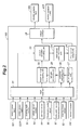
Figure 2 is a block diagram of a control system of the rear wheel toe angle control system; and -
Figure 3 is a flowchart showing a control routine of the rear wheel toe angle control system. - A rear wheel toe angle control system embodying the present invention is now described in the following with reference to the appended drawings. In the following description, the component parts associated with each wheel are denoted, in some places, with numerals including a suffix such as R and L indicating on which side the particular component is located, but in other places without a suffix to collectively denote the particular component parts.
- Referring to
Figure 1 illustrating a fourwheeled vehicle 1 incorporated with a rear wheel steering system embodying the present invention, thevehicle 1 comprises a pair offront wheels pneumatic tire rear wheels pneumatic tire vehicle body 2 viacorresponding knuckles wheel suspension units - The
vehicle 1 is provided with a frontwheel steering system 10 that allows the front wheels 4 to be directly steered by turning asteering wheel 11. The frontwheel steering system 10 comprises asteering shaft 12 connected to thesteering wheel 11, apinion 13 fixed to a lower end of thesteering shaft 12 and arack shaft 14 extending laterally and provided with rack teeth which mesh with thepinion 13. Therack shaft 12 is supported so as to be moveable along the lengthwise direction thereof, and has two ends that are connected to thecorresponding knuckles rack shaft 14 which is in turn caused by the turning of thesteering wheel 11. - The
steering shaft 12 is fitted with asteering angle sensor 51 which detects the angular position of thesteering wheel 11 as a measure of the actual steering angle of the front wheels. In the following description, it should be understood that thesteering angle sensor 51 produces a sensor signal that corresponds to the actual steering angle of the front wheels 4. Thesteering shaft 12 is additionally fitted with asteering torque sensor 53 that detects the steering torque or the torque applied to thesteering shaft 12 by a vehicle operator turning thesteering wheel 11. - The
vehicle 1 is provided with a leftelectric actuator 40L having a first end connected to thevehicle body 2 and a second end connected to theknuckle 21L of the leftrear wheel 6L for controlling the left rear wheel toe angle, and a rightelectric actuator 40R having a first end connected to thevehicle body 2 and a second end connected to theknuckle 21R of the rightrear wheel 6R for controlling the right rear wheel toe angle. Each electric actuator 40 includes an electric motor and a feed screw mechanism connected to an output shaft of the electric motor so that the rotation of the output shaft causes an output rod (second end) of the actuator 40 to extend and retract as desired, and this extending and retracting movement of the output rod causes the toe angle of the corresponding rear wheel to be changed in a corresponding manner. - Each electric actuator 40 is fitted with a stroke sensor 52 for detecting an actual stroke of the output rod thereof.
- The
vehicle 1 is additionally provided with avehicle speed sensor 54 for detecting the traveling speed of thevehicle 1, ayaw rate sensor 55 for detecting a yaw rate of the vehicle, anaccelerator pedal sensor 56 for detecting a depressing stroke of an accelerator pedal, abrake pedal sensor 57 for detecting a depressing stroke of a brake pedal and a lateral acceleration sensor (lateral G sensor) 58 for detecting a lateral acceleration of thevehicle 1. - Each electric actuator 40 is controlled by a rear wheel steering control unit (ECU) 100 which essentially consists of a microcomputer. As illustrated in
Figure 2 , the rear wheelsteering control unit 100 includes aninput interface 21 for receiving sensor signals from the various sensors, a target toeangle computing unit 22, a controldeviation computing unit 23, a manipulatedvalue computing unit 24, a drivecurrent output unit 25, anoutput interface 26, afailure diagnosis unit 27, acornering detecting unit 28 and a failsafe processing unit 29. - The target toe
angle computing unit 22 computes a target toe angle of each rear wheel as a normal control process according to the driving operation of the vehicle operator and operating condition of the vehicle such as a front wheel steering angle detected by the front wheelsteering angle sensor 51, a vehicle speed detected by the vehicle speed sensor 52, a yaw rate detected by theyaw rate sensor 55, an accelerator depression detected by theaccelerator pedal sensor 56, the brake pedal depression detected by thebrake pedal sensor 57 and a lateral acceleration detected by thelateral G sensor 58, and this control process is executed according to a prescribed control rule. The target toeangle computing unit 22 converts the target doe angle of each rear wheel 6 into a target stroke of the corresponding electric actuator 40. - The control
deviation computing unit 23 computes, for each electric actuator 40, a control deviation between the target stroke of the actuator computed by the target toeangle computing unit 22 and the actual stroke of the actuator detected by the corresponding stroke sensor 52. - The manipulated
value computing unit 24 computes the manipulated value for each electric actuator 40 so that the control deviation of the electric actuator computed by the controldeviation computing unit 23 may be minimized as a proportional feedback control of a prescribed gain. Thereby, the actual toe angle of the rear wheels 6 is controlled so as to follow or tract the target toe angle given at each moment. The drivecurrent output unit 25 converts the manipulated value into an electric current value (or a duty ratio) of the electric current which is actually supplied to the actuator 40 via theoutput interface 26. - When the rear wheels 6 are steered in a symmetric pattern, the toe-in and toe-out of the rear wheels can be changed as desired. When the rear wheels 6 are steered in a same direction, the four wheel steering of the vehicle can be achieved. If the rear wheels are steered in an opposite phase relationship to the front wheels, the maneuverability of the vehicle can be improved particularly in low speed ranges. If the rear wheels are steered in a same phase relationship to the front wheels, the motion stability of the vehicle can be improved particularly in high speed ranges.
- The
failure diagnosis unit 27 carries out a diagnosis of thesteering angle sensor 51 for detecting a steering angle of the front wheels that forwards a sensor output signal to theinput interface 21 for the rear wheel toe angle control, according to a prescribed diagnosis procedure, and thereby detects a failure of the sensor. As a possible modification of this embodiment, thefailure diagnosis unit 27 may diagnose at least a member selected from a group consisting of the front wheelsteering angle sensor 51, vehicle speed sensor 52,yaw rate sensor 55,accelerator pedal sensor 56,brake pedal sensor 57 andlateral G sensor 58. - The
cornering detecting unit 28 is activated when a failure of thesteering angle sensor 51 is detected by thefailure diagnosis unit 27, and detects a cornering maneuver of the vehicle by using a sensor other than thesteering angle sensor 51. Thesteering torque sensor 53,yaw rate sensor 55 and/orlateral G sensor 58 may be used as a sensor for detecting a cornering maneuver of the vehicle. Typically, a cornering maneuver is detected when the output signal of the selected sensor has exceeded a prescribed threshold value. When the diagnosed sensor is other than the front wheelsteering angle sensor 51, the front wheelsteering angle sensor 51 may also be used as a sensor for detecting the cornering of the vehicle. - When a failure of the
steering angle sensor 51 is detected, and a cornering maneuver is detected by thecornering detecting unit 28, the failsafe processing unit 29 forwards a command to the control target toeangle computing unit 22 so that the control target toe angle is maintained at the current value during the cornering maneuver, and upon completion of the cornering maneuver, the control target toe angle is set to zero. The neutralization of the rear wheel toe angle is thus initiated only after the cornering maneuver is completed. If appropriate, the neutralization of the rear wheel toe angle may be initiated as soon as the severity of the cornering maneuver has decline below a prescribed level which may be measured in terms of a lateral acceleration, yaw rate or steering torque, for instance. - Therefore, upon detection of a failure of the
steering angle sensor 51, if the vehicle is cornering, the rear wheel toe angle is maintained at the current value, and is not neutralized. Therefore, the vehicle operator is not discomforted or otherwise disturbed by a neutralizing action of the rear wheel. - As the neutralizing action of the rear wheel toe angle control is initiated substantially upon completion of the cornering, the vehicle operator is not disturbed by the neutralizing action even when the neutralization or restoring of the rear wheel toe angle to zero is carried out at a relatively rapid rate. Therefore, according to the illustrated embodiment, in case of a sensor failure, the neutralization of the rear toe angle is completed in a relatively short period of time when appropriate such as when the vehicle is traveling straight ahead, and the neutralization of the rear toe angle is delayed or suspended in other times such as when the vehicle is cornering.
- The control process of the rear wheel toe angle control system of the illustrated embodiment which is represented in the flowchart of
Figure 3 is executed as an interrupt routine of a main control routine which is involved at a regular interval. - First of all, the
control unit 100 receives sensor signals from the various sensors (step S11). A diagnosis of thesteering angle sensor 51 is executed, and a failure of thesteering angle sensor 51 is determined (step S12). If no failure of thesteering angle sensor 51 is detected, a normal toe angle control process is executed according to a prescribed normal rear wheel toe angle control rule (step S 13). - If a failure of the
steering angle sensor 51 is detected, it is then determined if the vehicle is cornering (step S 14). A cornering of the vehicle can be detected by determining if an output of thesteering torque sensor 53,yaw rate sensor 55 and/orlateral G sensor 58 has exceeded a prescribed threshold value. If the vehicle is cornering, the current rear wheel toe angle is maintained, and no action is taken to return the rear wheel toe angle to zero (step S 15). - On the other hand, if the vehicle is not cornering and traveling straight ahead or if the cornering of the vehicle has substantially ended, the rear wheel toe angle is reduced to zero at a prescribed rate (step S16).
- Although the present invention has been described in terms of a preferred embodiment thereof, it is obvious to a person skilled in the art that various alterations and modifications are possible without departing from the scope of the present invention which is set forth in the appended claims.
- The contents of the original Japanese patent application on which the Paris Convention priority claim is made for the present application are incorporated in this application by reference.
- Provided is a rear wheel toe angle control system for a four wheeled vehicle, comprising a first sensor (51) for detecting an operating condition of the vehicle, a target rear wheel toe angle setting unit (22) for setting a target rear wheel toe angle according to an output of the first sensor, an actuator (40) for steering rear wheels of the vehicle, a control unit (23, 24, 25) that actuates the actuator so as to make an actual rear wheel toe angle agree with the target rear wheel toe angle, a sensor failure detecting unit (27) for detecting a failure of the first sensor and a cornering detecting unit (28) for detecting a cornering maneuver of the vehicle by using a second sensor other than the first sensor. Upon detection of a sensor failure by the sensor failure detecting unit, the control unit maintains a current target rear wheel toe angle while the vehicle is cornering, and reduces the target rear wheel steering angle substantially to zero upon completion of the cornering of the vehicle. Thereby, the vehicle operator is not discomforted or otherwise disturbed by the fail safe action while the vehicle is cornering, but once the cornering is concluded, the fail safe action can be effected at a relatively rapid rate without causing any disturbance to the motion of the vehicle or discomforting the vehicle operator.
Claims (3)
- A rear wheel toe angle control system for a four wheeled vehicle, comprisinga first sensor (51) for detecting an operating condition of the vehicle,
a target rear wheel toe angle setting unit (22) for setting a target rear wheel toe angle according to an output of the first sensor,
an actuator (40) for steering rear wheels of the vehicle, and
a control unit (23, 24, 25) that actuates the actuator so as to make an actual rear wheel toe angle agree with the target rear wheel toe angle, characterized by that:the control system further comprises a sensor failure detecting unit (27) for detecting a failure of the first sensor and a cornering detecting unit (28) for detecting a cornering maneuver of the vehicle by using a second sensor other than the first sensor, and upon detection of a sensor failure by the sensor failure detecting unit, the control unit maintains a current target rear wheel toe angle while the vehicle is cornering, and reduces the target rear wheel steering angle substantially to zero upon completion of the cornering of the vehicle. - The rear wheel toe angle control system according to claim 1, wherein the first sensor comprises at least a member selected from a group consisting of a front wheel steering angle sensor (51), a vehicle speed sensor (52), a yaw rate sensor (55), an accelerator pedal sensor (56), a brake pedal sensor (57) and a lateral acceleration sensor (58).
- The rear wheel toe angle control system according to claim 1, wherein the second sensor comprises at least a member selected from a group consisting of a steering torque sensor (53), a front wheel steering angle sensor (51), a yaw rate sensor (55) and a lateral acceleration sensor (58).
Applications Claiming Priority (1)
| Application Number | Priority Date | Filing Date | Title |
|---|---|---|---|
| JP2009082321A JP2010234841A (en) | 2009-03-30 | 2009-03-30 | Rear wheel toe angle control device for vehicle |
Publications (2)
| Publication Number | Publication Date |
|---|---|
| EP2236393A1 true EP2236393A1 (en) | 2010-10-06 |
| EP2236393B1 EP2236393B1 (en) | 2011-02-16 |
Family
ID=42111885
Family Applications (1)
| Application Number | Title | Priority Date | Filing Date |
|---|---|---|---|
| EP20100157601 Expired - Fee Related EP2236393B1 (en) | 2009-03-30 | 2010-03-24 | Rear wheel toe angle control system |
Country Status (3)
| Country | Link |
|---|---|
| EP (1) | EP2236393B1 (en) |
| JP (1) | JP2010234841A (en) |
| DE (1) | DE602010000004D1 (en) |
Cited By (1)
| Publication number | Priority date | Publication date | Assignee | Title |
|---|---|---|---|---|
| US8666600B2 (en) | 2012-06-20 | 2014-03-04 | Honda Motor Co., Ltd. | Rear toe control system and method |
Families Citing this family (4)
| Publication number | Priority date | Publication date | Assignee | Title |
|---|---|---|---|---|
| FR2991960B1 (en) * | 2012-06-14 | 2015-10-16 | Renault Sas | METHOD FOR SECURING THE CONTROL OF THE REAR WHEELS OF A MOTOR VEHICLE EQUIPPED WITH AN ELECTRIC POWER STEERING |
| JP6252759B2 (en) * | 2013-08-26 | 2017-12-27 | 株式会社ジェイテクト | Electric power steering device |
| US10053148B2 (en) | 2015-06-15 | 2018-08-21 | GM Global Technology Operations LLC | Toe optimization system for a vehicle |
| JP6764503B2 (en) * | 2019-04-26 | 2020-09-30 | Ntn株式会社 | Actuator control device |
Citations (5)
| Publication number | Priority date | Publication date | Assignee | Title |
|---|---|---|---|---|
| US4953649A (en) * | 1987-12-10 | 1990-09-04 | Suzuki Jidosha Kogyo Kabushiki Kaisha | Four-wheel steering device for an automobile |
| US5014801A (en) * | 1988-02-10 | 1991-05-14 | Fuji Jukogyo Kabushiki Kaisha | Method and device for rear-wheel steering of automotive vehicle |
| EP0463310A1 (en) * | 1990-06-28 | 1992-01-02 | Bayerische Motoren Werke Aktiengesellschaft | Method for the operation of a steering apparatus for the rear wheels of a motor vehicle |
| JPH0930438A (en) | 1995-07-17 | 1997-02-04 | Honda Motor Co Ltd | Rear wheel steering device |
| JP2000055921A (en) | 1998-08-13 | 2000-02-25 | Kdk Corp | Test strip for urea determination |
Family Cites Families (4)
| Publication number | Priority date | Publication date | Assignee | Title |
|---|---|---|---|---|
| JP2521934B2 (en) * | 1986-12-22 | 1996-08-07 | トヨタ自動車株式会社 | Control device for rear wheel steering in front and rear wheel steering vehicle |
| JP4448838B2 (en) * | 2006-08-25 | 2010-04-14 | 本田技研工業株式会社 | Vehicle toe angle variable control device |
| JP4996280B2 (en) * | 2007-02-16 | 2012-08-08 | 本田技研工業株式会社 | Toe angle changing device |
| JP2009057011A (en) * | 2007-09-03 | 2009-03-19 | Toyota Motor Corp | Steering control device |
-
2009
- 2009-03-30 JP JP2009082321A patent/JP2010234841A/en active Pending
-
2010
- 2010-03-24 DE DE201060000004 patent/DE602010000004D1/en active Active
- 2010-03-24 EP EP20100157601 patent/EP2236393B1/en not_active Expired - Fee Related
Patent Citations (5)
| Publication number | Priority date | Publication date | Assignee | Title |
|---|---|---|---|---|
| US4953649A (en) * | 1987-12-10 | 1990-09-04 | Suzuki Jidosha Kogyo Kabushiki Kaisha | Four-wheel steering device for an automobile |
| US5014801A (en) * | 1988-02-10 | 1991-05-14 | Fuji Jukogyo Kabushiki Kaisha | Method and device for rear-wheel steering of automotive vehicle |
| EP0463310A1 (en) * | 1990-06-28 | 1992-01-02 | Bayerische Motoren Werke Aktiengesellschaft | Method for the operation of a steering apparatus for the rear wheels of a motor vehicle |
| JPH0930438A (en) | 1995-07-17 | 1997-02-04 | Honda Motor Co Ltd | Rear wheel steering device |
| JP2000055921A (en) | 1998-08-13 | 2000-02-25 | Kdk Corp | Test strip for urea determination |
Cited By (1)
| Publication number | Priority date | Publication date | Assignee | Title |
|---|---|---|---|---|
| US8666600B2 (en) | 2012-06-20 | 2014-03-04 | Honda Motor Co., Ltd. | Rear toe control system and method |
Also Published As
| Publication number | Publication date |
|---|---|
| EP2236393B1 (en) | 2011-02-16 |
| DE602010000004D1 (en) | 2011-03-31 |
| JP2010234841A (en) | 2010-10-21 |
Similar Documents
| Publication | Publication Date | Title |
|---|---|---|
| CN102596690B (en) | Device for controlling vehicle travel | |
| EP2428374B1 (en) | Rear wheel toe angle controller and reference position calibration method of electric actuator in rear wheel toe angle controller | |
| JP5140662B2 (en) | Rear wheel steering vehicle | |
| KR102274120B1 (en) | Control apparatus and method for rear wheel steering system | |
| JP2001322557A (en) | Multi-wheel independent steering system for vehicles | |
| CN101172488B (en) | Electric Power Steering | |
| EP2236393B1 (en) | Rear wheel toe angle control system | |
| JP5484447B2 (en) | Rear wheel toe angle control device for vehicle | |
| JP5313739B2 (en) | Rear wheel toe angle control device for vehicle | |
| JP2004255943A (en) | Vehicle control device | |
| JP5068638B2 (en) | Vehicle rear wheel toe angle control device and rear wheel toe angle control method | |
| JP5303333B2 (en) | Vehicle rear wheel steering control device | |
| JP5313714B2 (en) | Electric power steering device | |
| JP2013018381A (en) | Electric power steering device | |
| JP2010184509A (en) | Rear wheel steering device | |
| JP4956477B2 (en) | Rear wheel toe angle controller | |
| US20250128691A1 (en) | Steer-by-wire-system and method for same | |
| JP2007022170A (en) | Vehicle steering apparatus and vehicle deflection suppressing method | |
| JP5326019B2 (en) | Rear wheel toe angle controller | |
| WO2025173375A1 (en) | Turning control device, turning control method, turning control program, and turning device | |
| JP2728478B2 (en) | Vehicle rear wheel steering system | |
| JPH065950Y2 (en) | Rear wheel steering angle control device | |
| JPS60193773A (en) | Vehicle front and rear wheel steering device | |
| WO2026018589A1 (en) | Turn control device, turning device, turn control method, and turn control program | |
| JP5271640B2 (en) | Control device for electric power steering |
Legal Events
| Date | Code | Title | Description |
|---|---|---|---|
| PUAI | Public reference made under article 153(3) epc to a published international application that has entered the european phase |
Free format text: ORIGINAL CODE: 0009012 |
|
| 17P | Request for examination filed |
Effective date: 20100324 |
|
| AK | Designated contracting states |
Kind code of ref document: A1 Designated state(s): AT BE BG CH CY CZ DE DK EE ES FI FR GB GR HR HU IE IS IT LI LT LU LV MC MK MT NL NO PL PT RO SE SI SK SM TR |
|
| GRAP | Despatch of communication of intention to grant a patent |
Free format text: ORIGINAL CODE: EPIDOSNIGR1 |
|
| GRAS | Grant fee paid |
Free format text: ORIGINAL CODE: EPIDOSNIGR3 |
|
| GRAA | (expected) grant |
Free format text: ORIGINAL CODE: 0009210 |
|
| AK | Designated contracting states |
Kind code of ref document: B1 Designated state(s): DE FR |
|
| REF | Corresponds to: |
Ref document number: 602010000004 Country of ref document: DE Date of ref document: 20110331 Kind code of ref document: P |
|
| REG | Reference to a national code |
Ref country code: DE Ref legal event code: R096 Ref document number: 602010000004 Country of ref document: DE Effective date: 20110331 |
|
| PLBE | No opposition filed within time limit |
Free format text: ORIGINAL CODE: 0009261 |
|
| STAA | Information on the status of an ep patent application or granted ep patent |
Free format text: STATUS: NO OPPOSITION FILED WITHIN TIME LIMIT |
|
| 26N | No opposition filed |
Effective date: 20111117 |
|
| REG | Reference to a national code |
Ref country code: DE Ref legal event code: R097 Ref document number: 602010000004 Country of ref document: DE Effective date: 20111117 |
|
| PGFP | Annual fee paid to national office [announced via postgrant information from national office to epo] |
Ref country code: FR Payment date: 20130325 Year of fee payment: 4 Ref country code: DE Payment date: 20130320 Year of fee payment: 4 |
|
| REG | Reference to a national code |
Ref country code: DE Ref legal event code: R119 Ref document number: 602010000004 Country of ref document: DE |
|
| REG | Reference to a national code |
Ref country code: FR Ref legal event code: ST Effective date: 20141128 |
|
| REG | Reference to a national code |
Ref country code: DE Ref legal event code: R119 Ref document number: 602010000004 Country of ref document: DE Effective date: 20141001 |
|
| PG25 | Lapsed in a contracting state [announced via postgrant information from national office to epo] |
Ref country code: DE Free format text: LAPSE BECAUSE OF NON-PAYMENT OF DUE FEES Effective date: 20141001 Ref country code: FR Free format text: LAPSE BECAUSE OF NON-PAYMENT OF DUE FEES Effective date: 20140331 |