EP2236362A1 - Einachsiges Haubenscharnier eines Fahrzeuges - Google Patents
Einachsiges Haubenscharnier eines Fahrzeuges Download PDFInfo
- Publication number
- EP2236362A1 EP2236362A1 EP10466010A EP10466010A EP2236362A1 EP 2236362 A1 EP2236362 A1 EP 2236362A1 EP 10466010 A EP10466010 A EP 10466010A EP 10466010 A EP10466010 A EP 10466010A EP 2236362 A1 EP2236362 A1 EP 2236362A1
- Authority
- EP
- European Patent Office
- Prior art keywords
- hinge
- vehicle
- actuator
- leg
- shearing
- Prior art date
- Legal status (The legal status is an assumption and is not a legal conclusion. Google has not performed a legal analysis and makes no representation as to the accuracy of the status listed.)
- Granted
Links
- 238000010008 shearing Methods 0.000 claims description 22
- 239000003380 propellant Substances 0.000 description 3
- 208000027418 Wounds and injury Diseases 0.000 description 2
- 230000004913 activation Effects 0.000 description 2
- 230000008901 benefit Effects 0.000 description 2
- 230000006378 damage Effects 0.000 description 2
- 208000014674 injury Diseases 0.000 description 2
- 230000007246 mechanism Effects 0.000 description 2
- 241001416181 Axis axis Species 0.000 description 1
- 229910000831 Steel Inorganic materials 0.000 description 1
- 230000009471 action Effects 0.000 description 1
- 230000000712 assembly Effects 0.000 description 1
- 238000000429 assembly Methods 0.000 description 1
- 230000008859 change Effects 0.000 description 1
- 238000010276 construction Methods 0.000 description 1
- FDKCTEWMJWRPDS-UHFFFAOYSA-N dialuminum;trimagnesium;trisilicate Chemical compound [Mg+2].[Mg+2].[Mg+2].[Al+3].[Al+3].[O-][Si]([O-])([O-])[O-].[O-][Si]([O-])([O-])[O-].[O-][Si]([O-])([O-])[O-] FDKCTEWMJWRPDS-UHFFFAOYSA-N 0.000 description 1
- 238000004880 explosion Methods 0.000 description 1
- 230000003116 impacting effect Effects 0.000 description 1
- 238000009434 installation Methods 0.000 description 1
- 239000003973 paint Substances 0.000 description 1
- 229910052832 pyrope Inorganic materials 0.000 description 1
- 230000008439 repair process Effects 0.000 description 1
- 230000000284 resting effect Effects 0.000 description 1
- 239000010959 steel Substances 0.000 description 1
Images


Classifications
-
- B—PERFORMING OPERATIONS; TRANSPORTING
- B60—VEHICLES IN GENERAL
- B60R—VEHICLES, VEHICLE FITTINGS, OR VEHICLE PARTS, NOT OTHERWISE PROVIDED FOR
- B60R21/00—Arrangements or fittings on vehicles for protecting or preventing injuries to occupants or pedestrians in case of accidents or other traffic risks
- B60R21/34—Protecting non-occupants of a vehicle, e.g. pedestrians
- B60R21/38—Protecting non-occupants of a vehicle, e.g. pedestrians using means for lifting bonnets
Definitions
- the invention relates to a uniaxial front door hinge on a motor vehicle, which is located in the rear of the front door near the windscreen and is designed as an active front door hinge that lift the front door in a vehicle collision with a pedestrian and thus the risk of injury to persons through the under the front flap located fixed parts will reduce.
- the single-axis hinge includes an upper hinge leg attached to the front door and a lower hinge leg connected to this leg via a hinge axis and attached to the front carriage.
- the lower hinge leg includes a releasable in case of collision recess for attachment of the hinge axis.
- the uniaxial hinge is connected to a lifting element which comprises a force-locking actuator hinged to the lower hinge leg and a lifting element hinged to the upper hinge leg for lifting the upper hinge leg during impact.
- this solution forms the hinged directly to the hinge axis axis lifting element, the bearing identifies an independently resolvable position assurance at the lower hinge leg for attachment of the hinge joint axis.
- This position assurance is formed by a latching mechanism and a spring.
- the disadvantage of this position assurance is the constructive complexity and the associated higher financial cost of such device.
- a uniaxial front door hinge in the rear of the front door near the windshield which has a hinged leg connected to the vehicle front flap and a holder connected to the vehicle body, on which by means of a fastening means of the pyrotechnic actuator is attached, wherein the actuator Rod with an eyelet includes.
- a uniaxial hinge of the vehicle front flap further comprises a hinge attached to the holder of the front door, wherein the hinge of the hinge leg and the eye of the rod of the pyrotechnic actuator are connected.
- the illustration of the invention lies in the fact that the hinged hinge comprises a shearing element.
- the hinged hinge further includes an enclosing pad coaxially disposed between the shear element and the hinge leg and the eye of the actuator piston, the leg and the eye being pivotally mounted in the disk.
- the shearing member includes a shearing groove formed in the area between the pad of the tang and the hinge holder.
- the shear element is designed as a shear screw or shear pin.
- Fig. 1 is in the axonometric view of the uniaxial front flap hinge in the usual rest position shown in the Fig. 2 is the uniaxial hinge shown in cross-section
- Fig. 3 the detail of the uniaxial front flap hinge is shown in longitudinal section in the usual rest position
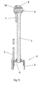
- Fig. 4 the axonometric view of the uniaxial hinge is shown in the extended active position in which Fig. 5 a detail of the uniaxial hinge is shown in longitudinal section in the extended active position.
- the uniaxial front door hinge of the vehicle is shown, which is located in the rear of the front door near the windscreen and is designed as an active front door hinge that raises the front door in a vehicle collision with a pedestrian and thus the risk of injury to persons will reduce by the located under the front flap fixed parts.
- the uniaxial front flap hinge of the vehicle comprises a hinge leg 1 connected to the vehicle front flap and a holder 2 connected to the vehicle body, on which the pyrotechnic actuator 11 is fastened by means of a fastening means 11 .
- the holder 2 of the hinge is connected to the body by means of the screws 13 .
- the actuator 11 includes a rod 7 which includes an eyelet 8 .
- the pyrotechnic actuator 11 further includes a cylinder 5, a piston 7 attached to the rod 6 and, disposed under the piston 6 Pyropatrone 12th
- the uniaxial front door hinge of the vehicle is further formed by a hinge 3 attached to the holder 2 of the hinge.
- the hinge 3 is further the hinge leg 2 and the eyelet 8 of the rod 7 of the pyrotechnic actuator 4 is connected.
- the hinged hinge 3 includes a shearing element 9 and an enclosing pad 14 coaxially disposed on the shearing element.
- the washer 14 is inserted between the shearing element 9 and hinge leg 1 and eyelet 8 of the rod 7 of the actuator 4 , wherein the leg 1 and the eyelet 8 are pivotally connected in the pad 14 .
- the shearing element 9 includes a shearing groove 10 which is formed on the shear element 9 at the location between the pad 14 of the hinge pin 3 and the holder 2 of the hinge.
- the shear element 9 is designed as a shear screw or as a shear pin.
- the uniaxial hinge is on both sides of the front flap.
- the whole system functions like a standard uniaxial hinge of the vehicle front flap.
- the pyrotechnic propellant charge When activated by the control unit, the pyrotechnic propellant charge is ignited in the Pyropatrone 12 . As a result, a large increase in pressure in the area below the piston 6 is generated. This pressure begins to act with great force on the piston 6 and thereby stress the shearing element 9 to shearing.
- This shearing element 9 is designed so that after the ignition of the Pyropatrone 12 at the location of the created Abschernut 10 comes to its shearing. After shearing the shearing element 9 , the hinge leg 1 is moved very quickly by the action of the piston 6 and the rod 7 , until the whole mechanism in the top dead center, ie. enters the extended active position. As a result, the hinge leg 1 is moved together with the front flap.
- suitable parameter setting of the pyrotechnic propellant charge of the pyropatron 12 and design of the mechanical assemblies the entire system is adjusted so that the front flap is raised in a predetermined time and by predetermined lift.
- the area where the explosion takes place is so protected from the safety point of view that no flame outside of the cylinder area 5 can strike and possibly cause a fire.
- This movement increases the distance between the front door and the fixed engine parts and the surrounding engine accessories. Increasing the distance creates a more constant deceleration of the impacting person while reducing the possibility of contact with the fixed engine parts and accessories located in the area under the front door.
- the Pyropatrone 12 is installed in the body as a replacement part. This allows easy repair and especially the basic hinge to the body in Install raw condition so that the front door can be installed and set up before the vehicle paint. The subsequent installation of Pyropatrone 12 will not affect the fit of the front door and change. This is a very important advantage of the solution mentioned.
- This system of pyrotechnic activation single axis hinge according to the invention can be used in all vehicles.
Landscapes
- Engineering & Computer Science (AREA)
- Mechanical Engineering (AREA)
- Superstructure Of Vehicle (AREA)
Abstract
Description
- Die Erfindung betrifft ein einachsiges Frontklappenscharnier an einem Kraftfahrzeug, das sich im hinteren Bereich der Frontklappe in der Nähe der Frontscheibe befindet und als aktives Frontklappenscharnier ausgeführt ist, das bei einer Fahrzeugkollision mit einem Fußgänger die Frontklappe anheben und so das Risiko der Verletzung von Personen durch die unter der Frontklappe befindlichen festen Teile mindern wird.
- Aus dem Dokument
DE 10 2006 033 720 A1 ist die Fußgängerschutzeinrichtung beim drohenden Sturz auf die Frontklappe bekannt, die über ein einachsiges Scharnier am Vorderwagen befestigt ist. Das einachsige Scharnier umfasst einen an der Frontklappe befestigten oberen Scharnierschenkel und einen mit diesem Schenkel über eine Scharniergelenkachse verbundenen und am Vorderwagen befestigten unteren Scharnierschenkel. Der untere Scharnierschenkel enthält eine beim eventuellen Zusammenstoß auflösbare Aussparung für die Befestigung der Scharniergelenkachse. Dem einachsigen Scharnier ist ein Hubelement angeschlossen, das einen am unteren Scharnierschenkel gelenkgebundenen kraftspeichernden Aktuator und ein am oberen Scharnierschenkel gelenkgebundenes Hubelement zur Anhebung des oberen Scharnierschenkels beim Aufprall umfasst. Die Darstellung dieser Lösung bildet das direkt an der Scharniergelenkachse gelenkgebundene Hubelement, wobei die Lagerung am unteren Scharnierschenkel für die Befestigung der Scharniergelenkachse eine selbständig auflösbare Positionssicherung ausweist. Diese Positionssicherung wird durch ein Rastmechanismus und eine Feder gebildet. Der Nachteil dieser Positionssicherung ist die konstruktive Kompliziertheit und der damit verbundene höhere Finanzaufwand solcher Vorrichtung. - Die Aufgabe wird durch ein einachsiges Frontklappenscharnier im hinteren Bereich der Frontklappe in der Nähe der Frontscheibe gelöst, das einen mit der Fahrzeugfrontklappe verbundenen Scharnierschenkel und einen mit der Fahrzeugkarosserie verbundenen Halter umfasst, auf dem mittels eines Befestigungsmittels der pyrotechnische Aktuator befestigt ist, wobei der Aktuator eine Stange mit einer Öse umfasst. Einachsiges Scharnier der Fahrzeugfrontklappe umfasst ferner eine am Halter befestigte Scharnierangel der Frontklappe, wobei zur Angel der Scharnierschenkel und die Öse der Stange des pyrotechnischen Aktuators angeschlossen sind.
- Die Darstellung der Erfindung liegt darin, dass die Scharnierangel ein Abscherelement umfasst. Die Scharnierangel enthält weiter eine umschließende Unterlage, die koaxial zwischen dem Abscherelement und dem Scharnierschenkel und der Öse des Aktuatorkolbens angeordnet ist, wobei der Schenkel und die Öse in der Scheibe schwenkbar befestigt sind. Das Abscherelement enthält eine Abschernut, die im Bereich zwischen der Unterlage der Angel und dem Scharnierhalter ausgebildet ist. Das Abscherelement ist als eine Abscherschraube oder ein Abscherbolzen ausgebildet.
- In der
Fig. 1 ist in der axonometrischen Ansicht das einachsige Frontklappenscharnier in der üblichen Ruhelage dargestellt, in derFig. 2 ist das einachsige Scharnier im Querschnitt dargestellt, in derFig. 3 ist das Detail des einachsigen Frontklappenscharniers im Längsschnitt in der üblichen Ruhelage dargestellt, in derFig. 4 ist die axonometrische Ansicht des einachsigen Scharniers in der ausgefahrenen Aktivstellung dargestellt, in derFig. 5 ist ein Detail des einachsigen Scharniers im Längsschnitt in der ausgefahrenen Aktivstellung dargestellt. - In der
Fig. 1, 2 und3 ist in der Ausgangsruhelage das einachsige Frontklappenscharnier des Fahrzeuges dargestellt, das sich im hinteren Bereich der Frontklappe in der Nähe der Frontscheibe befindet und als ein aktives Frontklappenscharnier ausgebildet ist, das bei einer Fahrzeugkollision mit einem Fußgänger die Frontklappe anheben und so das Risiko der Verletzung von Personen durch die unter der Frontklappe befindlichen festen Teile mindern wird. Das einachsige Frontklappenscharnier des Fahrzeuges umfasst einen mit der Fahrzeugfrontklappe verbundenen Scharnierschenkel 1 und einen mit der Fahrzeugkarosserie verbundenen Halter 2, auf dem mittels eines Befestigungsmittels 11 der pyrotechnische Aktuator 11 befestigt ist. Der Halter 2 des Scharniers ist mit der Karosserie mittels der Schrauben 13 verbunden. Der Aktuator 11 enthält eine Stange 7, die eine Öse 8 umfasst. Der pyrotechnische Aktuator 11 umfasst weiter einen Zylinder 5, einen an der Stange 7 befestigten Kolben 6 und eine unter dem Kolben 6 angeordnete Pyropatrone 12. - Das einachsige Frontklappenscharnier des Fahrzeuges wird weiter durch eine am Halter 2 des Scharniers befestigte Angel 3 gebildet. Mit der Angel 3 ist weiter der Scharnierschenkel 2 und die Öse 8 der Stange 7 des pyrotechnischen Aktuators 4 verbunden.
- Die Scharnierangel 3 enthält ein Abscherelement 9 und einen umschließende Unterlage 14, die an dem Abscherelement koaxial angeordnet ist. Die Unterlegscheibe 14 ist zwischen das Abscherelement 9 und Scharnierschenkel 1 und Öse 8 der Stange 7 des Aktuators 4 eingelegt, wobei der Schenkel 1 und die Öse 8 schwenkbar in der Unterlage 14 verbunden sind. Das Abscherelement 9 enthält eine Abschernut 10, die auf dem Abscherelement 9 an der Stelle zwischen der Unterlage 14 der Scharnierangel 3 und dem Halter 2 des Scharniers ausgebildet wird. Das Abscherelement 9 ist als eine Abscherschraube oder als ein Abscherbolzen ausgebildet.
- In der
Fig. 4 und5 ist das einachsige Frontklappenscharnier des Fahrzeuges in der ausgefahrenen Aktivstellung dargestellt. - Das einachsige Scharnier ist an beiden Seiten der Frontklappe ausgeführt.
- Im eingebauten Zustand, dh. in der Ausgangsruhelage, funktioniert das ganze System wie ein standardmäßiges einachsiges Scharnier der Fahrzeugfrontklappe.
- Bei einer Aktivierung durch die Steuereinheit wird die pyrotechnische Treibladung in der Pyropatrone 12 gezündet. Dadurch wird ein großer Druckanstieg im Bereich unter dem Kolben 6 erzeugt. Dieser Druck beginnt mit großer Kraft auf den Kolben 6 zu wirken und dadurch das Abscherelement 9 auf Abscherung zu beanspruchen. Dieses Abscherelement 9 ist so ausgelegt, damit nach der Zündung der Pyropatrone 12 an der Stelle der erstellten Abschernut 10 zu seiner Abscherung kommt. Nach der Abscherung des Abscherelementes 9 wird durch die Einwirkung des Kolbens 6 und der Stange 7 der Scharnierschenkel 1 sehr schnell bewegt, bis der ganze Mechanismus in den oberen Totpunkt, dh. in die ausgefahrene Aktivstellung gelangt. Dadurch wird der Scharnierschenkel 1 zusammen mit der Frontklappe bewegt. Durch geeignete Parametereinstellung der pyrotechnischen Treibladung der Pyropatrone 12 und Auslegung der mechanischen Baugruppen wird das ganze System so eingestellt, damit die Frontklappe in vorgegebener Zeit und um vorgegebenen Hubmaß angehoben wird.
- Der Bereich, wo die Explosion erfolgt, ist vom Sicherheitsgesichtspunkt so abgesichert, damit keine Flamme außerhalb des Zylinderbereiches 5 aufschlagen und eventuellen Brand verursachen kann.
- Dieses System des einachsigen Frontklappenscharniers mit pyrotechnischer Aktivierung aufgrund der Informationen von elektronischer Steuereinheit hebt die Frontklappe im Scharnierbereich um ca. 100mm an, was den neuen Vorgaben für die Fahrzeugsicherheitslösungen von Sicht des sog. aktiven Fußgängerschutzes entspricht. Mit dieser Bewegung erhöht sich die Distanz zwischen der Frontklappe und der festen Motorteilen und des umliegenden Motorzubehörs. Die Vergrößerung der Distanz schafft eine stetigere Verzögerung der aufprallenden Person und reduziert zugleich die Möglichkeit des Kontaktes mit den festen Motorteilen und - zubehör, die sich im Bereich unter der Frontklappe befinden.
- Der Vorteil dieser Lösung liegt in der einfachen, leichten Konstruktion, da zum Ausfahren keine starke Stahlfeder, sondern eine pyrotechnische Treibladung eingesetzt wird, die eine schnelle und verlässliche Funktion des Scharniers sichert.
- Diese Lösung ermöglicht Wiederverwendung der Teile, nur mit dem Austausch der Pyropatrone 12 und dem Einsatz eines neuen Abscherelementes 9 in der Scharnierangel 3.
- Die Pyropatrone 12 wird in die Karosserie als Austauschteil eingebaut. Dies ermöglicht einfache Reparatur und vor allem das Grundscharnier an die Karosse im Rohzustand einzubauen, sodass die Frontklappe vor der Fahrzeuglackierung eingebaut und eingerichtet werden kann. Der nachträgliche Einbau der Pyropatrone 12 wird die Passung der Frontklappe keineswegs beeinflussen und ändern. Dies ist ein sehr wichtiger Vorteil der angeführten Lösung.
- Für den Fall einer beschränkten Lebensdauer der Pyropatrone 12 ist derer Austausch ohne Ausbau des Frontklappenscharniers sehr einfach durchführbar.
- Dieses System des einachsigen Scharniers mit pyrotechnischer Aktivierung gemäß Erfindung kann in allen Fahrzeugen eingesetzt werden.
-
- 1
- Scharnierschenkel
- 2
- Scharnierhalter
- 3
- Scharnierangel
- 4
- pyrotechnischer Aktuator
- 5
- Aktuatorzylinder
- 6
- Aktuatorkolben
- 7
- Aktuatorstange
- 8
- Öse der Aktuatorstange
- 9
- Abscherelement der Angel
- 10
- Abschernut des Abscherelementes
- 11
- Befestigungsmittel
- 12
- Pyropatrone des Aktuators
- 13
- Befestigungsschraube des Halters
- 14
- umschließende Unterlage der Angel
Claims (5)
- Einachsiges Frontklappenscharnier des Fahrzeuges, das im hinteren Bereich der Frontklappe in der Nähe der Frontscheibe angeordnet ist, umfasst
einen mit der Frontklappe verbundenen Scharnierschenkel (1),
einen mit der Fahrzeugkarosserie verbundenen Halter (2), auf dem mittels Befestigungsmittel , (11) der pyrotechnische Aktuator (4) befestigt ist, wobei der Aktuator (4) eine Stange (7) mit Öse (8) umfasst,
sowie eine am Halter (2) befestigte Scharnierangel (3), wobei mit der Angel (3) ein Scharnierschenkei (1) und die Öse (8) der Stange (7) des pyrotechnischen Aktuators (4) verbunden sind dadurch gekennzeichnet ist, dass die Scharnierangel (3) ein Abscherelement (9) umfasst. - Einachsiges Scharnier nach Anspruch 1 dadurch gekennzeichnet, dass die Scharnierangel (3) eine umschließende Unterlage (14) aufweist, die koaxial zwischen dem Abscherelement (9) und zwischen dem Scharnierschenkel (1) sowie der Öse (8) des Aktuators (4) angeordnet ist, wobei der Schenkel (1) und die Öse (8) schwenkbar mit der Unterlage (14) verbunden sind.
- Einachsiges Scharnier nach Anspruch 1 und 2 dadurch gekennzeichnet, dass das Abscherelement (9) eine Abschernut (10) aufweist, die auf dem Abscherelement (9) an der Stelle zwischen der Unterlage (14) der Angel (3) und dem Scharnierhalter (2) ausgebildet ist.
- Einachsiges Scharnier nach Ansprüchen 1 bis 3 dadurch
gekennzeichnet, dass das Abscherelement (9) als eine Abscherschraube ausgebildet ist. - Einachsiges Scharnier nach Ansprüchen 1 bis 3 dadurch gekennzeichnet, dass das Abscherelement (9) als Abscherbolzen ausgebildet ist.
Applications Claiming Priority (1)
| Application Number | Priority Date | Filing Date | Title |
|---|---|---|---|
| CZ20090195A CZ2009195A3 (cs) | 2009-03-31 | 2009-03-31 | Jednoosý záves kapoty vozidla |
Publications (2)
| Publication Number | Publication Date |
|---|---|
| EP2236362A1 true EP2236362A1 (de) | 2010-10-06 |
| EP2236362B1 EP2236362B1 (de) | 2012-03-21 |
Family
ID=42288513
Family Applications (1)
| Application Number | Title | Priority Date | Filing Date |
|---|---|---|---|
| EP10466010A Not-in-force EP2236362B1 (de) | 2009-03-31 | 2010-03-24 | Einachsiges Haubenscharnier eines Fahrzeuges |
Country Status (3)
| Country | Link |
|---|---|
| EP (1) | EP2236362B1 (de) |
| AT (1) | ATE550229T1 (de) |
| CZ (1) | CZ2009195A3 (de) |
Citations (2)
| Publication number | Priority date | Publication date | Assignee | Title |
|---|---|---|---|---|
| EP1705382A1 (de) * | 2005-03-24 | 2006-09-27 | Mazda Motor Corporation | Sicherheitseinrichtung für ein Kraftfahrzeug |
| DE102006033720A1 (de) | 2006-07-21 | 2008-01-24 | Automotive Group Ise Innomotive Systems Europe Gmbh | Vorrichtung zum aktiven Aufstellen der Fronthaube eines Kraftfahrzeuges bei einem drohenden Personenaufprall |
-
2009
- 2009-03-31 CZ CZ20090195A patent/CZ2009195A3/cs unknown
-
2010
- 2010-03-24 EP EP10466010A patent/EP2236362B1/de not_active Not-in-force
- 2010-03-24 AT AT10466010T patent/ATE550229T1/de active
Patent Citations (2)
| Publication number | Priority date | Publication date | Assignee | Title |
|---|---|---|---|---|
| EP1705382A1 (de) * | 2005-03-24 | 2006-09-27 | Mazda Motor Corporation | Sicherheitseinrichtung für ein Kraftfahrzeug |
| DE102006033720A1 (de) | 2006-07-21 | 2008-01-24 | Automotive Group Ise Innomotive Systems Europe Gmbh | Vorrichtung zum aktiven Aufstellen der Fronthaube eines Kraftfahrzeuges bei einem drohenden Personenaufprall |
Also Published As
| Publication number | Publication date |
|---|---|
| EP2236362B1 (de) | 2012-03-21 |
| ATE550229T1 (de) | 2012-04-15 |
| CZ2009195A3 (cs) | 2010-10-13 |
Similar Documents
| Publication | Publication Date | Title |
|---|---|---|
| DE102007033325B4 (de) | Scharnier | |
| EP1716023B1 (de) | Anordnung einer frontklappe mit verstellhebel an einem fahrzeug | |
| DE10102760B4 (de) | Sicherheitssysteme mit einer aufpralldämpfenden Fronthaube an einem Fahrzeug | |
| DE102016113684A1 (de) | Scharniervorrichtung mit einem integrierten Fußgängerschutz für eine Fronthaube | |
| DE10116717B4 (de) | Scharniereinrichtung für eine anhebbare Fronthaube an einem Fahrzeug | |
| DE10305685B4 (de) | Fußgängerschutzeinrichtung an einem Kraftfahrzeug | |
| DE102010029719B4 (de) | Scharnier für eine Frontklappe eines Kraftfahrzeugs | |
| EP2055538A1 (de) | Fronthaubenscharnier | |
| DE202004002480U1 (de) | Anordnung einer Frontklappe mit Verstellhebel an einem Fahrzeug | |
| DE102009040410A1 (de) | Scharnier und Verfahren zum Betreiben eines Scharniers | |
| EP2236362B1 (de) | Einachsiges Haubenscharnier eines Fahrzeuges | |
| DE102009040401B4 (de) | Scharnier für ein Fahrzeug | |
| WO2011026811A1 (de) | Scharnier und verfahren zum betreiben eines scharniers | |
| WO2005044645A1 (de) | Aktuator für ein aufprallschutzsystem eines fahrzeugs | |
| DE102009040416A1 (de) | Fahrzeug-Sicherheitseinrichtung mit einem ersten Scharnierteil und einem an diesem schwenkbar gelagerten zweiten Scharnierteil | |
| DE10332818A1 (de) | Vorrichtung zum Anheben einer Motorhaube | |
| EP2243669B1 (de) | Fronthaubenscharnier zur gelenkigen Anordnung einer Fronthaube an einem Fahrzeug | |
| EP2733025B1 (de) | Fronthaubenscharnier mit pyrotechnischer Antriebsvorrichtung | |
| DE102009040417A1 (de) | Fahrzeug-Sicherheitseinrichtung mit einem schwenkbaren Scharnierteil | |
| DE102004055604A1 (de) | Scharnier | |
| DE102011075267B4 (de) | Scharniereinrichtung für eine Frontklappe eines Kraftfahrzeugs, die in eine Fußgängerschutzlage hochstellbar ist | |
| DE102009033723B4 (de) | Einrichtung zum Anheben eines Karosserieteils eines Kraftfahrzeuges | |
| DE102015013707A1 (de) | Fahrzeug mit einer anhebbaren Motorhaube | |
| DE102014010871B4 (de) | Fahrzeug | |
| DE102018215767A1 (de) | Scharniersystem einer Frontklappe eines Fahrzeugs |
Legal Events
| Date | Code | Title | Description |
|---|---|---|---|
| PUAI | Public reference made under article 153(3) epc to a published international application that has entered the european phase |
Free format text: ORIGINAL CODE: 0009012 |
|
| AK | Designated contracting states |
Kind code of ref document: A1 Designated state(s): AT BE BG CH CY CZ DE DK EE ES FI FR GB GR HR HU IE IS IT LI LT LU LV MC MK MT NL NO PL PT RO SE SI SK SM TR |
|
| AX | Request for extension of the european patent |
Extension state: AL BA ME RS |
|
| 17P | Request for examination filed |
Effective date: 20110406 |
|
| GRAP | Despatch of communication of intention to grant a patent |
Free format text: ORIGINAL CODE: EPIDOSNIGR1 |
|
| RIC1 | Information provided on ipc code assigned before grant |
Ipc: B60R 21/34 20110101AFI20110607BHEP |
|
| GRAS | Grant fee paid |
Free format text: ORIGINAL CODE: EPIDOSNIGR3 |
|
| GRAA | (expected) grant |
Free format text: ORIGINAL CODE: 0009210 |
|
| AK | Designated contracting states |
Kind code of ref document: B1 Designated state(s): AT BE BG CH CY CZ DE DK EE ES FI FR GB GR HR HU IE IS IT LI LT LU LV MC MK MT NL NO PL PT RO SE SI SK SM TR |
|
| REG | Reference to a national code |
Ref country code: GB Ref legal event code: FG4D Free format text: NOT ENGLISH |
|
| REG | Reference to a national code |
Ref country code: CH Ref legal event code: EP |
|
| REG | Reference to a national code |
Ref country code: IE Ref legal event code: FG4D Free format text: LANGUAGE OF EP DOCUMENT: GERMAN |
|
| REG | Reference to a national code |
Ref country code: AT Ref legal event code: REF Ref document number: 550229 Country of ref document: AT Kind code of ref document: T Effective date: 20120415 |
|
| REG | Reference to a national code |
Ref country code: DE Ref legal event code: R096 Ref document number: 502010000552 Country of ref document: DE Effective date: 20120516 |
|
| REG | Reference to a national code |
Ref country code: NL Ref legal event code: VDEP Effective date: 20120321 |
|
| PG25 | Lapsed in a contracting state [announced via postgrant information from national office to epo] |
Ref country code: LT Free format text: LAPSE BECAUSE OF FAILURE TO SUBMIT A TRANSLATION OF THE DESCRIPTION OR TO PAY THE FEE WITHIN THE PRESCRIBED TIME-LIMIT Effective date: 20120321 Ref country code: NO Free format text: LAPSE BECAUSE OF FAILURE TO SUBMIT A TRANSLATION OF THE DESCRIPTION OR TO PAY THE FEE WITHIN THE PRESCRIBED TIME-LIMIT Effective date: 20120621 Ref country code: HR Free format text: LAPSE BECAUSE OF FAILURE TO SUBMIT A TRANSLATION OF THE DESCRIPTION OR TO PAY THE FEE WITHIN THE PRESCRIBED TIME-LIMIT Effective date: 20120321 |
|
| LTIE | Lt: invalidation of european patent or patent extension |
Effective date: 20120321 |
|
| PG25 | Lapsed in a contracting state [announced via postgrant information from national office to epo] |
Ref country code: LV Free format text: LAPSE BECAUSE OF FAILURE TO SUBMIT A TRANSLATION OF THE DESCRIPTION OR TO PAY THE FEE WITHIN THE PRESCRIBED TIME-LIMIT Effective date: 20120321 Ref country code: GR Free format text: LAPSE BECAUSE OF FAILURE TO SUBMIT A TRANSLATION OF THE DESCRIPTION OR TO PAY THE FEE WITHIN THE PRESCRIBED TIME-LIMIT Effective date: 20120622 Ref country code: FI Free format text: LAPSE BECAUSE OF FAILURE TO SUBMIT A TRANSLATION OF THE DESCRIPTION OR TO PAY THE FEE WITHIN THE PRESCRIBED TIME-LIMIT Effective date: 20120321 |
|
| PG25 | Lapsed in a contracting state [announced via postgrant information from national office to epo] |
Ref country code: CY Free format text: LAPSE BECAUSE OF FAILURE TO SUBMIT A TRANSLATION OF THE DESCRIPTION OR TO PAY THE FEE WITHIN THE PRESCRIBED TIME-LIMIT Effective date: 20120321 |
|
| BERE | Be: lapsed |
Owner name: SKODA AUTO A.S. Effective date: 20120331 |
|
| PG25 | Lapsed in a contracting state [announced via postgrant information from national office to epo] |
Ref country code: RO Free format text: LAPSE BECAUSE OF FAILURE TO SUBMIT A TRANSLATION OF THE DESCRIPTION OR TO PAY THE FEE WITHIN THE PRESCRIBED TIME-LIMIT Effective date: 20120321 Ref country code: MC Free format text: LAPSE BECAUSE OF NON-PAYMENT OF DUE FEES Effective date: 20120331 Ref country code: SE Free format text: LAPSE BECAUSE OF FAILURE TO SUBMIT A TRANSLATION OF THE DESCRIPTION OR TO PAY THE FEE WITHIN THE PRESCRIBED TIME-LIMIT Effective date: 20120321 Ref country code: PL Free format text: LAPSE BECAUSE OF FAILURE TO SUBMIT A TRANSLATION OF THE DESCRIPTION OR TO PAY THE FEE WITHIN THE PRESCRIBED TIME-LIMIT Effective date: 20120321 Ref country code: SI Free format text: LAPSE BECAUSE OF FAILURE TO SUBMIT A TRANSLATION OF THE DESCRIPTION OR TO PAY THE FEE WITHIN THE PRESCRIBED TIME-LIMIT Effective date: 20120321 Ref country code: EE Free format text: LAPSE BECAUSE OF FAILURE TO SUBMIT A TRANSLATION OF THE DESCRIPTION OR TO PAY THE FEE WITHIN THE PRESCRIBED TIME-LIMIT Effective date: 20120321 Ref country code: IS Free format text: LAPSE BECAUSE OF FAILURE TO SUBMIT A TRANSLATION OF THE DESCRIPTION OR TO PAY THE FEE WITHIN THE PRESCRIBED TIME-LIMIT Effective date: 20120721 |
|
| PG25 | Lapsed in a contracting state [announced via postgrant information from national office to epo] |
Ref country code: SK Free format text: LAPSE BECAUSE OF FAILURE TO SUBMIT A TRANSLATION OF THE DESCRIPTION OR TO PAY THE FEE WITHIN THE PRESCRIBED TIME-LIMIT Effective date: 20120321 Ref country code: PT Free format text: LAPSE BECAUSE OF FAILURE TO SUBMIT A TRANSLATION OF THE DESCRIPTION OR TO PAY THE FEE WITHIN THE PRESCRIBED TIME-LIMIT Effective date: 20120723 |
|
| REG | Reference to a national code |
Ref country code: IE Ref legal event code: MM4A |
|
| PLBE | No opposition filed within time limit |
Free format text: ORIGINAL CODE: 0009261 |
|
| STAA | Information on the status of an ep patent application or granted ep patent |
Free format text: STATUS: NO OPPOSITION FILED WITHIN TIME LIMIT |
|
| PG25 | Lapsed in a contracting state [announced via postgrant information from national office to epo] |
Ref country code: NL Free format text: LAPSE BECAUSE OF FAILURE TO SUBMIT A TRANSLATION OF THE DESCRIPTION OR TO PAY THE FEE WITHIN THE PRESCRIBED TIME-LIMIT Effective date: 20120321 Ref country code: DK Free format text: LAPSE BECAUSE OF FAILURE TO SUBMIT A TRANSLATION OF THE DESCRIPTION OR TO PAY THE FEE WITHIN THE PRESCRIBED TIME-LIMIT Effective date: 20120321 Ref country code: IE Free format text: LAPSE BECAUSE OF NON-PAYMENT OF DUE FEES Effective date: 20120324 Ref country code: BE Free format text: LAPSE BECAUSE OF NON-PAYMENT OF DUE FEES Effective date: 20120331 |
|
| 26N | No opposition filed |
Effective date: 20130102 |
|
| PG25 | Lapsed in a contracting state [announced via postgrant information from national office to epo] |
Ref country code: MK Free format text: LAPSE BECAUSE OF FAILURE TO SUBMIT A TRANSLATION OF THE DESCRIPTION OR TO PAY THE FEE WITHIN THE PRESCRIBED TIME-LIMIT Effective date: 20120321 |
|
| REG | Reference to a national code |
Ref country code: DE Ref legal event code: R097 Ref document number: 502010000552 Country of ref document: DE Effective date: 20130102 |
|
| PG25 | Lapsed in a contracting state [announced via postgrant information from national office to epo] |
Ref country code: ES Free format text: LAPSE BECAUSE OF FAILURE TO SUBMIT A TRANSLATION OF THE DESCRIPTION OR TO PAY THE FEE WITHIN THE PRESCRIBED TIME-LIMIT Effective date: 20120702 |
|
| PG25 | Lapsed in a contracting state [announced via postgrant information from national office to epo] |
Ref country code: MT Free format text: LAPSE BECAUSE OF FAILURE TO SUBMIT A TRANSLATION OF THE DESCRIPTION OR TO PAY THE FEE WITHIN THE PRESCRIBED TIME-LIMIT Effective date: 20120321 Ref country code: BG Free format text: LAPSE BECAUSE OF FAILURE TO SUBMIT A TRANSLATION OF THE DESCRIPTION OR TO PAY THE FEE WITHIN THE PRESCRIBED TIME-LIMIT Effective date: 20120621 |
|
| PG25 | Lapsed in a contracting state [announced via postgrant information from national office to epo] |
Ref country code: TR Free format text: LAPSE BECAUSE OF FAILURE TO SUBMIT A TRANSLATION OF THE DESCRIPTION OR TO PAY THE FEE WITHIN THE PRESCRIBED TIME-LIMIT Effective date: 20120321 |
|
| PG25 | Lapsed in a contracting state [announced via postgrant information from national office to epo] |
Ref country code: LU Free format text: LAPSE BECAUSE OF NON-PAYMENT OF DUE FEES Effective date: 20120324 Ref country code: SM Free format text: LAPSE BECAUSE OF FAILURE TO SUBMIT A TRANSLATION OF THE DESCRIPTION OR TO PAY THE FEE WITHIN THE PRESCRIBED TIME-LIMIT Effective date: 20120321 |
|
| PGFP | Annual fee paid to national office [announced via postgrant information from national office to epo] |
Ref country code: IT Payment date: 20140327 Year of fee payment: 5 |
|
| PG25 | Lapsed in a contracting state [announced via postgrant information from national office to epo] |
Ref country code: HU Free format text: LAPSE BECAUSE OF FAILURE TO SUBMIT A TRANSLATION OF THE DESCRIPTION OR TO PAY THE FEE WITHIN THE PRESCRIBED TIME-LIMIT Effective date: 20100324 |
|
| REG | Reference to a national code |
Ref country code: CH Ref legal event code: PL |
|
| PG25 | Lapsed in a contracting state [announced via postgrant information from national office to epo] |
Ref country code: LI Free format text: LAPSE BECAUSE OF NON-PAYMENT OF DUE FEES Effective date: 20140331 Ref country code: CH Free format text: LAPSE BECAUSE OF NON-PAYMENT OF DUE FEES Effective date: 20140331 |
|
| PG25 | Lapsed in a contracting state [announced via postgrant information from national office to epo] |
Ref country code: IT Free format text: LAPSE BECAUSE OF NON-PAYMENT OF DUE FEES Effective date: 20150324 |
|
| REG | Reference to a national code |
Ref country code: FR Ref legal event code: PLFP Year of fee payment: 7 |
|
| REG | Reference to a national code |
Ref country code: AT Ref legal event code: MM01 Ref document number: 550229 Country of ref document: AT Kind code of ref document: T Effective date: 20150324 |
|
| PG25 | Lapsed in a contracting state [announced via postgrant information from national office to epo] |
Ref country code: AT Free format text: LAPSE BECAUSE OF NON-PAYMENT OF DUE FEES Effective date: 20150324 |
|
| REG | Reference to a national code |
Ref country code: FR Ref legal event code: PLFP Year of fee payment: 8 |
|
| REG | Reference to a national code |
Ref country code: FR Ref legal event code: PLFP Year of fee payment: 9 |
|
| PGFP | Annual fee paid to national office [announced via postgrant information from national office to epo] |
Ref country code: CZ Payment date: 20201126 Year of fee payment: 12 |
|
| PGFP | Annual fee paid to national office [announced via postgrant information from national office to epo] |
Ref country code: FR Payment date: 20210326 Year of fee payment: 12 |
|
| PGFP | Annual fee paid to national office [announced via postgrant information from national office to epo] |
Ref country code: GB Payment date: 20210326 Year of fee payment: 12 |
|
| PGFP | Annual fee paid to national office [announced via postgrant information from national office to epo] |
Ref country code: DE Payment date: 20210527 Year of fee payment: 12 |
|
| REG | Reference to a national code |
Ref country code: DE Ref legal event code: R119 Ref document number: 502010000552 Country of ref document: DE |
|
| PG25 | Lapsed in a contracting state [announced via postgrant information from national office to epo] |
Ref country code: CZ Free format text: LAPSE BECAUSE OF NON-PAYMENT OF DUE FEES Effective date: 20220324 |
|
| GBPC | Gb: european patent ceased through non-payment of renewal fee |
Effective date: 20220324 |
|
| PG25 | Lapsed in a contracting state [announced via postgrant information from national office to epo] |
Ref country code: GB Free format text: LAPSE BECAUSE OF NON-PAYMENT OF DUE FEES Effective date: 20220324 Ref country code: FR Free format text: LAPSE BECAUSE OF NON-PAYMENT OF DUE FEES Effective date: 20220331 Ref country code: DE Free format text: LAPSE BECAUSE OF NON-PAYMENT OF DUE FEES Effective date: 20221001 |