EP2235854B1 - Adapter, arrangement and method - Google Patents
Adapter, arrangement and method Download PDFInfo
- Publication number
- EP2235854B1 EP2235854B1 EP07852067.3A EP07852067A EP2235854B1 EP 2235854 B1 EP2235854 B1 EP 2235854B1 EP 07852067 A EP07852067 A EP 07852067A EP 2235854 B1 EP2235854 B1 EP 2235854B1
- Authority
- EP
- European Patent Office
- Prior art keywords
- adapter
- power
- port
- telecommunications network
- optic
- Prior art date
- Legal status (The legal status is an assumption and is not a legal conclusion. Google has not performed a legal analysis and makes no representation as to the accuracy of the status listed.)
- Not-in-force
Links
Images

Classifications
-
- G—PHYSICS
- G02—OPTICS
- G02B—OPTICAL ELEMENTS, SYSTEMS OR APPARATUS
- G02B6/00—Light guides; Structural details of arrangements comprising light guides and other optical elements, e.g. couplings
- G02B6/24—Coupling light guides
- G02B6/42—Coupling light guides with opto-electronic elements
- G02B6/4201—Packages, e.g. shape, construction, internal or external details
- G02B6/4274—Electrical aspects
- G02B6/4284—Electrical aspects of optical modules with disconnectable electrical connectors
-
- H—ELECTRICITY
- H04—ELECTRIC COMMUNICATION TECHNIQUE
- H04B—TRANSMISSION
- H04B10/00—Transmission systems employing electromagnetic waves other than radio-waves, e.g. infrared, visible or ultraviolet light, or employing corpuscular radiation, e.g. quantum communication
- H04B10/50—Transmitters
Definitions
- the present invention concerns an adapter and an arrangement comprising an adapter for use in a telecommunications network, such as an Ethernet network.
- the method also concerns a method for allowing a user to transform at least one power port, such as a power-over-Ethernet (PoE) port of an Ethernet switch, or at least one electric signal input/output port of a telecommunications network switch, into at least one optic port.
- PoE power-over-Ethernet
- a telecommunications network is a network of telecommunications links and nodes arranged so that messages may be passed from one part of the network to another over multiple links and through various nodes.
- the Ethernet is, for example, a family of frame-based computer networking technologies for local area networks (LANs).
- Ethernet networks use twisted-pair cables or fibre optics to connect network devices to a common medium that provides a path along which electric signals can travel.
- Such telecommunications networks can transmit data at transfer rates of up to 10 gigabits per second (Gbps).
- Switches are used to connect network segments and comprise either electric ports for the input/output of electric signals, optic ports for the input/output of optic signals, or a combination of both electric and optic ports. Most electric ports are arranged to receive a standardized registered jack, such as an RJ45 (i.e. a standardized physical interface for connecting telecommunications equipment or computer networking equipment). Many switches also comprise power ports that can be used to transmit electric power, along with data, to remote devices over standard electric cables.
- a standardized registered jack such as an RJ45 (i.e. a standardized physical interface for connecting telecommunications equipment or computer networking equipment).
- Many switches also comprise power ports that can be used to transmit electric power, along with data, to remote devices over standard electric cables.
- a fibre converter is usually connected, via an RJ45 cable for example, to an electric port of the switch.
- a fibre converter contains an optic transceiver that converts optic signals into electric signals and vice versa, and it must be supplied with electric power in order to function. Connecting a fibre converter to a switch therefore increases the cost, complexity, installation time and space requirements of a telecommunications network switch system.
- telecommunications network switches comprising an optic port may be used although such switches are more expensive than switches that comprise only electric ports (with or without the power function).
- WO 2004/010755 discloses a media wall converter housing that fits into an existing faceplate of a wall outlet.
- the converter has a front section for housing converter circuitry and a rear section for housing optical components.
- the rear section of the adapter housing resides behind the faceplate while the front section of the housing extends into a work area from the faceplate.
- US 2004/0081465 concerns a system and method for supplying driving power to media converters for optical communication, which can realize a communication system employing a simple circuit construction at a minimal expense even in the case where the communication system includes a plurality of media converters.
- Each media converter converts an interface of an electrical-communication device to an interface of an optical-communication device and converts the interface of the optical-communication device to the interface of the electrical-communication device.
- the system includes: a power-supply device constructed independently from the media converters: and, at least one power-supply socket device to supply power from the power-supply device to the media converters.
- a media converter for use in optical-to-electrical and electrical-to-optical conversion.
- a media converter includes an outer housing, an electrical plug disposed on one end of the outer housing, an optical cable disposed on an opposite end of the outer housing, and circuitry that connects to both the electrical plug and the optical cable.
- the circuitry receives electrical signals from the electrical plug and outputs corresponding optical signals to the optical cable.
- the circuitry also receives optical signals from the optical cable and outputs corresponding electrical signals to the electrical plug.
- An object of the present invention is to provide a means for enabling a telecommunications network switch having no optic ports to be fed with an optical signal in a rational manner.
- an adapter that comprises: at least one first connector for connecting at least one optic transceiver to the adapter and at least one second connector for directly connecting the adapter to at least one power port of a telecommunications network switch, such as a power-over-Ethernet (PoE) port of an Ethernet switch or a Power over LAN (PoL) port or an Inline Power port.
- a telecommunications network switch such as a power-over-Ethernet (PoE) port of an Ethernet switch or a Power over LAN (PoL) port or an Inline Power port.
- PoE power-over-Ethernet
- PoL Power over LAN
- Inline Power port Inline Power port
- the adapter also comprises second circuitry arranged to enable electric power to be drawn from at least one power port of the telecommunications network switch to enable power to be supplied to the at least one optic transceiver.
- the adapter is thereby arranged to enable electric signals to be transmitted therethrough while electric power is simultaneously fed to the optical transceiver and/or any parts of the adapter's circuitry requiring electric power.
- the at least one second connector is arranged to releasably directly connect the adapter to the at least one power port of a telecommunications network switch.
- the invention is based on the realisation that a telecommunications switch having no optic ports may be fed with an optical signal using such an adapter.
- an optic transceiver When at least one optic transceiver has been connected to the adapter and power from at least one power port of the telecommunications network switch has been supplied to the at least one optic transceiver, electric signals may be transmitted between the at least one optic transceiver and the telecommunications network switch via the adapter. The at least one (electric) power port is thereby transformed into at least one optic port.
- the adapter may be connected to an external power supply to draw power therefrom instead of, or in addition to drawing power from a power port of the telecommunications network switch, if desired.
- the second circuitry to draw electric power from the at least one power port of the telecommunications network may of course be (at least partly) by-passed, or omitted from the adapter altogether, if an external power supply is used to power the at least one optic transceiver (i.e. an external power source may be connected directly to the optic transceiver or it may be connected to the optic transceiver via the adapter).
- an external power supply is used to power the at least one optic transceiver
- an external power source may be connected directly to the optic transceiver or it may be connected to the optic transceiver via the adapter.
- the adapter according to the invention functions solely as an attachment to enable the output of at least one optic transceiver to be quickly and easily connected directly to at least one port of a telecommunications network switch (i.e. an electric power port or an electric signal input/output port).
- the at least one power port is a registered jack port, such as an RJ 11, RJ 14 or RJ45 port.
- the at least one first connector is arranged to releasably connect the at least one optic transceiver to the adapter.
- the adapter may comprise a plurality of different first and/or second connectors in order to enable the adapter to be connected to a plurality of different optic transceivers and/or a plurality of different power ports.
- the at least one first connecter is arranged for connecting at least one optic transceiver in the form of a Gigabit Interface Converter (GBIC) or a Small-Form factor-Pluggable (SFP) module to the adapter.
- GBIC Gigabit Interface Converter
- SFP Small-Form factor-Pluggable
- Such optic transceivers offer high speed data transfer (1 Gbps and higher) and physical compactness and they can be removed and replaced without damaging or disturbing the rest of the system that comprises the GBIC or SFP.
- the adapter comprises at least one indicator to indicate the presence of an optic signal in the at least one optic transceiver, once at least one optic transceiver has been connected to the adapter.
- the adaptor comprises at least one indicator to indicate the status/operation of the adapter.
- the at least one indicator may comprise at least one light emitting diode (LED) and/or an acoustic/vibration alarm and/or means to provide information concerning the status/operation of the adapter to a user, control system or database.
- the first circuitry is arranged to process or modulate electric signals that are transmitted therethrough, for example to de-noise or vary the amplitude, frequency, or phase of the electric signals. If electric power is required to power such first circuitry, it may be drawn from a power port of the communications network switch.
- the adapter comprises a plurality of first connectors for connecting a plurality of optic transceivers to the adapter and/or a plurality of second connectors for directly connecting the adapter to a plurality of power ports.
- a single adapter may therefore be arranged to be connected to a plurality of power ports of a telecommunications network switch and/or a plurality of optic transceivers.
- the adaptor may be connected to the power ports of a plurality of different communications network switches, one adapter may for example be connected between two or more communications network switches. This is advantageous since it, for example, allows ten power ports with a data transfer rate of 1 Gbit/s each to be multiplexed in the adapter and output as a 10 Gbit/s optical signal.
- the adapter comprises first circuitry to transmit a signal from one power port of a telecommunications network switch to a plurality of optic transceivers and/or first circuitry to transmit a signal from one optic transceiver to a plurality of power ports of a telecommunications network switch.
- an output signal from one power port of a telecommunications network switch may be transmitted/multi-casted/broadcasted through a plurality of channels, for example.
- the adapter comprises means to enable a user to connect/disconnect various power paths through the adapter so that he/she can, for example, decide which of a plurality of optic transceivers should be supplied with power.
- an adapter's first circuitry may comprise means, such as switches, to allow a user to select how signals are to be transmitted through the adapter so that one adapter may be used for a plurality of different applications.
- Such means may be arranged to be manoeuvred manually or remotely.
- First circuitry may for example be connected/disconnected by sending a control signal to the means that allow a user to select how signals are to be transmitted through the adapter.
- the adapter is arranged to accommodate the at least part of the at least one optic transceiver inside the adapter.
- An optic transceiver such as an SFP
- an adapter that contains an Ethernet transceiver to convert an electric signal from an Ethernet switch to an electrical signal suitable for the SFP.
- the present invention also concerns an arrangement for use in a telecommunications network, such as an Ethernet network, whereby the arrangement comprises an adapter according to any of the embodiments of the invention to which at least one optic transceiver, such as a Gigabit Interface Converter (GBIC) or a Small-Form factor-Pluggable (SFP) module, is releasably or non-releasably connected.
- a telecommunications network such as an Ethernet network
- at least one optic transceiver such as a Gigabit Interface Converter (GBIC) or a Small-Form factor-Pluggable (SFP) module, is releasably or non-releasably connected.
- GBIC Gigabit Interface Converter
- SFP Small-Form factor-Pluggable
- the present invention also concerns a method for allowing a user to transform at least one power port of a telecommunications network switch, such as a power-over-Ethernet (PoE) port of an Ethernet switch, into at least one optic port.
- the method comprises the step of connecting at least one adapter according to any of the embodiments of the invention or at least one arrangement according any of the embodiments of the invention to at least one power port of a telecommunications network switch.
- the present invention further concerns a method for allowing a user to transform at least one electric signal input/output port (i.e. an electric port that is not also a power port) of a telecommunications network switch into at least one optic signal input/output port.
- the method comprises the step of connecting at least one adapter according to any of the embodiments of the invention, or at least one arrangement according any of the embodiments of the invention, to at least one electric signal input/output port of a telecommunications network switch.
- the adapter, arrangement and methods according to the present invention are intended for use particularly, but not exclusively, in an Ethernet network.
- the Ethernet is standardized as IEEE 802.3, which is a collection of IEEE standards defining the physical layer, and the media access control (MAC) sublayer of the data link layer of the wired Ethernet.
- This is generally a local area network (LAN) technology with some wide area network (WAN) applications in which physical connections are made between nodes and/or infrastructure devices, such as hubs, switches, routers, by various types of electric conductor, such as copper wire, or optic fibre cable.
- LAN local area network
- WAN wide area network
- the adapter, arrangement and methods according to the present invention are however suitable for use in any type of telecommunications network, such as a computer network, the Internet, the Public Switched Telephone Network or an air traffic control network.
- FIG. 1 shows a commercially available Ethernet switch 10 comprising a plurality of electric ports 12.
- a plurality of electric conductors 14, such as RJ45s and their wiring, are connected to transmit electric signals (e) to and/or from the Ethernet switch 10 via the electric ports 12.
- a fibre converter 16 is connected to the outermost electric port on the left-hand side of the Ethernet switch 10 illustrated in figure 1 , via an RJ45 cable 14 for example.
- the fibre converter 16 contains an optic transceiver to convert optic signals (o) from a telecommunications network node or device, such as an IP telephone, camera, embedded computer, hub, switch or router into electric signals (e) and vice versa.
- the fibre converter 16 comprises an optic port 18 for the input/output of optic signals (o) and it must be supplied with electric power P from an external power source 20.
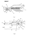
- FIG. 2 shows an adapter 22 according to an embodiment of the invention.
- the adapter 22 comprises a first connector 24 for releasably connecting an optic transceiver 26, such as a Small-Form factor-Pluggable (SFP) module, to the adapter 22.
- the adapter 22 and optic transceiver 26 may however example non-releasably connected together and provided as a unitary arrangement 28.
- the adapter 22 also comprises a second connector 30 for releasably or non-releasably directly connecting the adapter 22 (or the arrangement 28) to a power port 32, of a telecommunications network switch 10, such as a RJ45 power-over-Ethernet (PoE) port of an Ethernet switch.
- the adapter 22 comprises shielded or non-shielded first circuitry 36 arranged to enable electric signals to be transmitted between the optic transceiver 26 and the power port 32.
- the adapter 22 also comprises second circuitry 37 to draw power (P) from the power port 32 of the telecommunications network switch 10, to enable power to be supplied to the optic transceiver 26.
- the adapter 22 may comprise any electrically insulating flexible or non-flexible material such as glass fibre, a plastic, a prepreg (i.e. a combination of glass fibre mat, non-woven material and resin), a polyimide, Teflon ® or a ceramic.
- the adapter may be of any shape and size, depending on the application. It should be noted that the adapter 22 need not necessarily be constituted of a single component, but it may for example be constructed from a plurality of components that are selectively connected together to form the adapter 22. Such a multi-component adapter structure enables a user to easily modify an adapter's first an/or second circuitry.
- the adaptor 22 may for example comprise a metallic or plastic housing and at least one first connector 24 for connecting at least one optic transceiver 26 to the adapter 22 and at least one second connector 30 for directly connecting the adapter 22 to at least one PoE power port 32 of an Ethernet switch 10.
- the first and second connectors 24 and 30 may be arranged on a printed circuit board comprising the first circuitry 36 of the adapter 22.
- the first circuitry 34 may comprise an Ethernet transceiver circuit to convert an electric signal from the Ethernet switch 10 into an electric signal suitable for the optic transceiver 26.
- the printed circuit board may also comprise a (DC/DC) voltage converter arranged to convert a 48V PoE power supply into the typical 3.3V power supply for the Ethernet transceiver circuit.
- the adapter illustrated in figure 2 comprises an indicator 34, such as a light emitting diode (LED) to indicate the presence of an optic signal (o) in the optic transceiver 26, once the optic transceiver has been connected to the adapter 22, or to indicate the status/operation of the adapter 22.
- the adapter 22 may additionally or alternatively comprise an acoustic/vibration alarm to indicate that the adapter/arrangement is, for example, not functioning correctly to a user or control system.
- the adapter 22 or the arrangement 28 may be arranged to provide information concerning its status/operation.
- An adapter according to the invention may of course comprise any number of indicators for the same of different types of information.
- the adapter 22 may be arranged to transmit electric signals (e) between the optic transceiver 26 and the telecommunications network switch 10 without modification or it may comprise any conventional circuitry that enables electric signals (e) that are transmitted therethrough to be processed or modulated.
- Electric signals (e) from a network device may for example be de-noised and/or their amplitude, frequency, or phase may be varied as they pass through the adapter 22, before they are transmitted to the electric port 32 of a telecommunications network switch 10.
- an adapter 22 or arrangement 28 allows a user to transform at least one port, i.e. a power port or an electric signal input/output port, of a telecommunications network switch by simply connecting at least one such adapter 22 or arrangement 28 to at least one of the ports 30 of the telecommunications network switch 10.
- FIG. 3 shows an adapter 22 that is connected to a communications network switch 10, viewed from above.
- the adapter 22 comprises a plurality of first connectors 24 for connecting a plurality of optic transceivers to the adapter 22 and a plurality of second connectors 30 for directly connecting the adapter 22 to a plurality of power ports of a telecommunications network switch 10.
- the adapter 22 illustrated in figure 3 comprises shielded or non-shielded first circuitry 36 to transmit electric signals (e) between each power port of the telecommunications network switch 10 and a corresponding optic transceiver that is electrically connected to each power port via the adapter 22.
- the illustrated adapter 22 is arranged to accommodate the entire optic transceiver 26 inside the adapter 22.
- the adapter 22 may therefore function as an interference shield not only to prevent interference between electric conductors of the first circuitry 36 but also to prevent interference between the optic transceiver 26, the first and second circuitry and any other components/devices in the vicinity of the communications network switch 10.
- Figure 4 shows an adapter 22 that is connected to a communications network switch 10, viewed from above.
- the adapter 22 comprises a plurality of first connectors 24 for connecting a plurality of optic transceivers to the adapter 22 and a plurality of second connectors 30 for directly connecting the adapter 22 to a plurality of power ports of a telecommunications network switch 10.
- the adapter 22 illustrated in figure 4 comprises first circuitry 36 to transmit electric signals (e) between a single power port of a telecommunications network switch 10 and a plurality of optic transceivers that are electrically connected to that power port.
- a single adapter may be arranged to contain both the first circuitry 36 shown in figure 3 and the first circuitry 36 shown in figure 4 and it may comprise means to allow a user to select how electric signals are to be transmitted through the adapter 22 depending on the application.
- a user may for example be given the option of switching between the first circuitry shown in figure 3 and the first circuitry shown in figure 4 and/or he/she may be given the option of connecting/disconnecting various electric signal paths through the adapter 22.
- the adapters 22 shown in figures 3 and 4 also comprise second circuitry (not shown) to draw power from one or more power ports of a telecommunications network switch 10, to enable power to be supplied to one or more optic transceivers connected to the adapter 22.
- a user may be given the option of connecting/disconnecting various power paths through the adapter 22.
Description
- The present invention concerns an adapter and an arrangement comprising an adapter for use in a telecommunications network, such as an Ethernet network. The method also concerns a method for allowing a user to transform at least one power port, such as a power-over-Ethernet (PoE) port of an Ethernet switch, or at least one electric signal input/output port of a telecommunications network switch, into at least one optic port.
- A telecommunications network is a network of telecommunications links and nodes arranged so that messages may be passed from one part of the network to another over multiple links and through various nodes. The Ethernet is, for example, a family of frame-based computer networking technologies for local area networks (LANs). Ethernet networks use twisted-pair cables or fibre optics to connect network devices to a common medium that provides a path along which electric signals can travel. Such telecommunications networks can transmit data at transfer rates of up to 10 gigabits per second (Gbps).
- Switches are used to connect network segments and comprise either electric ports for the input/output of electric signals, optic ports for the input/output of optic signals, or a combination of both electric and optic ports. Most electric ports are arranged to receive a standardized registered jack, such as an RJ45 (i.e. a standardized physical interface for connecting telecommunications equipment or computer networking equipment). Many switches also comprise power ports that can be used to transmit electric power, along with data, to remote devices over standard electric cables.
- If an optic port is required when using a switch comprising only electric ports, a fibre converter is usually connected, via an RJ45 cable for example, to an electric port of the switch. A fibre converter contains an optic transceiver that converts optic signals into electric signals and vice versa, and it must be supplied with electric power in order to function. Connecting a fibre converter to a switch therefore increases the cost, complexity, installation time and space requirements of a telecommunications network switch system. Alternatively, telecommunications network switches comprising an optic port may be used although such switches are more expensive than switches that comprise only electric ports (with or without the power function).
-
WO 2004/010755 discloses a media wall converter housing that fits into an existing faceplate of a wall outlet. The converter has a front section for housing converter circuitry and a rear section for housing optical components. The rear section of the adapter housing resides behind the faceplate while the front section of the housing extends into a work area from the faceplate. -
US 2004/0081465 concerns a system and method for supplying driving power to media converters for optical communication, which can realize a communication system employing a simple circuit construction at a minimal expense even in the case where the communication system includes a plurality of media converters. Each media converter converts an interface of an electrical-communication device to an interface of an optical-communication device and converts the interface of the optical-communication device to the interface of the electrical-communication device. The system includes: a power-supply device constructed independently from the media converters: and, at least one power-supply socket device to supply power from the power-supply device to the media converters. -
US 2007/010132 describes media converters for use in optical-to-electrical and electrical-to-optical conversion. A media converter includes an outer housing, an electrical plug disposed on one end of the outer housing, an optical cable disposed on an opposite end of the outer housing, and circuitry that connects to both the electrical plug and the optical cable. The circuitry receives electrical signals from the electrical plug and outputs corresponding optical signals to the optical cable. In addition, the circuitry also receives optical signals from the optical cable and outputs corresponding electrical signals to the electrical plug. - An object of the present invention is to provide a means for enabling a telecommunications network switch having no optic ports to be fed with an optical signal in a rational manner.
- This object is achieved by an adapter that comprises: at least one first connector for connecting at least one optic transceiver to the adapter and at least one second connector for directly connecting the adapter to at least one power port of a telecommunications network switch, such as a power-over-Ethernet (PoE) port of an Ethernet switch or a Power over LAN (PoL) port or an Inline Power port. As used in this document, the expression "directly" meaning without the use of an electric conductor/cable, such as an RJ45 and its associated wiring. The adapter comprises first circuitry arranged to enable electric signals to be transmitted between the at least one optic transceiver and the at least one power port. The adapter also comprises second circuitry arranged to enable electric power to be drawn from at least one power port of the telecommunications network switch to enable power to be supplied to the at least one optic transceiver. The adapter is thereby arranged to enable electric signals to be transmitted therethrough while electric power is simultaneously fed to the optical transceiver and/or any parts of the adapter's circuitry requiring electric power. The at least one second connector is arranged to releasably directly connect the adapter to the at least one power port of a telecommunications network switch.
- The invention is based on the realisation that a telecommunications switch having no optic ports may be fed with an optical signal using such an adapter. When at least one optic transceiver has been connected to the adapter and power from at least one power port of the telecommunications network switch has been supplied to the at least one optic transceiver, electric signals may be transmitted between the at least one optic transceiver and the telecommunications network switch via the adapter. The at least one (electric) power port is thereby transformed into at least one optic port.
- By drawing power for an optic transceiver from a power port, no external power source is necessary to power the optic transceiver, which reduces cost, complexity, installation time and space requirements. However, the adapter may be connected to an external power supply to draw power therefrom instead of, or in addition to drawing power from a power port of the telecommunications network switch, if desired.
- The second circuitry to draw electric power from the at least one power port of the telecommunications network may of course be (at least partly) by-passed, or omitted from the adapter altogether, if an external power supply is used to power the at least one optic transceiver (i.e. an external power source may be connected directly to the optic transceiver or it may be connected to the optic transceiver via the adapter). In such cases, the adapter according to the invention functions solely as an attachment to enable the output of at least one optic transceiver to be quickly and easily connected directly to at least one port of a telecommunications network switch (i.e. an electric power port or an electric signal input/output port).
- According to an embodiment of the invention the at least one power port is a registered jack port, such as an RJ 11, RJ 14 or RJ45 port.
- According to another embodiment of the invention the at least one first connector is arranged to releasably connect the at least one optic transceiver to the adapter.
- The adapter may comprise a plurality of different first and/or second connectors in order to enable the adapter to be connected to a plurality of different optic transceivers and/or a plurality of different power ports.
- According to an embodiment of the invention the at least one first connecter is arranged for connecting at least one optic transceiver in the form of a Gigabit Interface Converter (GBIC) or a Small-Form factor-Pluggable (SFP) module to the adapter. Such optic transceivers offer high speed data transfer (1 Gbps and higher) and physical compactness and they can be removed and replaced without damaging or disturbing the rest of the system that comprises the GBIC or SFP.
- According to another embodiment of the invention the adapter comprises at least one indicator to indicate the presence of an optic signal in the at least one optic transceiver, once at least one optic transceiver has been connected to the adapter. Additionally or alternatively, the adaptor comprises at least one indicator to indicate the status/operation of the adapter. The at least one indicator may comprise at least one light emitting diode (LED) and/or an acoustic/vibration alarm and/or means to provide information concerning the status/operation of the adapter to a user, control system or database.
- According to a further embodiment of the invention the first circuitry is arranged to process or modulate electric signals that are transmitted therethrough, for example to de-noise or vary the amplitude, frequency, or phase of the electric signals. If electric power is required to power such first circuitry, it may be drawn from a power port of the communications network switch.
- According to an embodiment of the invention the adapter comprises a plurality of first connectors for connecting a plurality of optic transceivers to the adapter and/or a plurality of second connectors for directly connecting the adapter to a plurality of power ports. A single adapter may therefore be arranged to be connected to a plurality of power ports of a telecommunications network switch and/or a plurality of optic transceivers. Furthermore, the adaptor may be connected to the power ports of a plurality of different communications network switches, one adapter may for example be connected between two or more communications network switches. This is advantageous since it, for example, allows ten power ports with a data transfer rate of 1 Gbit/s each to be multiplexed in the adapter and output as a 10 Gbit/s optical signal.
- According to another embodiment of the invention the adapter comprises first circuitry to transmit a signal from one power port of a telecommunications network switch to a plurality of optic transceivers and/or first circuitry to transmit a signal from one optic transceiver to a plurality of power ports of a telecommunications network switch. In this way an output signal from one power port of a telecommunications network switch may be transmitted/multi-casted/broadcasted through a plurality of channels, for example. According to an embodiment of the invention the adapter comprises means to enable a user to connect/disconnect various power paths through the adapter so that he/she can, for example, decide which of a plurality of optic transceivers should be supplied with power.
- According to an embodiment of the invention an adapter's first circuitry may comprise means, such as switches, to allow a user to select how signals are to be transmitted through the adapter so that one adapter may be used for a plurality of different applications. Such means may be arranged to be manoeuvred manually or remotely. First circuitry may for example be connected/disconnected by sending a control signal to the means that allow a user to select how signals are to be transmitted through the adapter.
- According to an embodiment of the invention the adapter is arranged to accommodate the at least part of the at least one optic transceiver inside the adapter. An optic transceiver, such as an SFP, may for example be connected to an adapter that contains an Ethernet transceiver to convert an electric signal from an Ethernet switch to an electrical signal suitable for the SFP.
- The present invention also concerns an arrangement for use in a telecommunications network, such as an Ethernet network, whereby the arrangement comprises an adapter according to any of the embodiments of the invention to which at least one optic transceiver, such as a Gigabit Interface Converter (GBIC) or a Small-Form factor-Pluggable (SFP) module, is releasably or non-releasably connected.
- The present invention also concerns a method for allowing a user to transform at least one power port of a telecommunications network switch, such as a power-over-Ethernet (PoE) port of an Ethernet switch, into at least one optic port. The method comprises the step of connecting at least one adapter according to any of the embodiments of the invention or at least one arrangement according any of the embodiments of the invention to at least one power port of a telecommunications network switch.
- The present invention further concerns a method for allowing a user to transform at least one electric signal input/output port (i.e. an electric port that is not also a power port) of a telecommunications network switch into at least one optic signal input/output port. The method comprises the step of connecting at least one adapter according to any of the embodiments of the invention, or at least one arrangement according any of the embodiments of the invention, to at least one electric signal input/output port of a telecommunications network switch.
- The adapter, arrangement and methods according to the present invention are intended for use particularly, but not exclusively, in an Ethernet network. The Ethernet is standardized as IEEE 802.3, which is a collection of IEEE standards defining the physical layer, and the media access control (MAC) sublayer of the data link layer of the wired Ethernet. This is generally a local area network (LAN) technology with some wide area network (WAN) applications in which physical connections are made between nodes and/or infrastructure devices, such as hubs, switches, routers, by various types of electric conductor, such as copper wire, or optic fibre cable. It should however be noted that the adapter, arrangement and methods according to the present invention are however suitable for use in any type of telecommunications network, such as a computer network, the Internet, the Public Switched Telephone Network or an air traffic control network.
- The present invention will hereinafter be further explained by means of non-limiting examples with reference to the appended figures where;
- Figure 1
- schematically shows a commercially available telecommunications network switch, and
- Figures 2-4
- schematically show adapters according to different embodiments of the invention,
- It should be noted that the drawings have not been drawn to scale and that the dimensions of certain features have been exaggerated for the sake of clarity.
-
Figure 1 shows a commerciallyavailable Ethernet switch 10 comprising a plurality ofelectric ports 12. A plurality ofelectric conductors 14, such as RJ45s and their wiring, are connected to transmit electric signals (e) to and/or from theEthernet switch 10 via theelectric ports 12. - A
fibre converter 16 is connected to the outermost electric port on the left-hand side of theEthernet switch 10 illustrated infigure 1 , via anRJ45 cable 14 for example. Thefibre converter 16 contains an optic transceiver to convert optic signals (o) from a telecommunications network node or device, such as an IP telephone, camera, embedded computer, hub, switch or router into electric signals (e) and vice versa. Thefibre converter 16 comprises anoptic port 18 for the input/output of optic signals (o) and it must be supplied with electric power P from anexternal power source 20. -
Figure 2 shows anadapter 22 according to an embodiment of the invention. Theadapter 22 comprises afirst connector 24 for releasably connecting anoptic transceiver 26, such as a Small-Form factor-Pluggable (SFP) module, to theadapter 22. Theadapter 22 andoptic transceiver 26 may however example non-releasably connected together and provided as aunitary arrangement 28. - The
adapter 22 also comprises asecond connector 30 for releasably or non-releasably directly connecting the adapter 22 (or the arrangement 28) to apower port 32, of atelecommunications network switch 10, such as a RJ45 power-over-Ethernet (PoE) port of an Ethernet switch. Theadapter 22 comprises shielded or non-shieldedfirst circuitry 36 arranged to enable electric signals to be transmitted between theoptic transceiver 26 and thepower port 32. Theadapter 22 also comprisessecond circuitry 37 to draw power (P) from thepower port 32 of thetelecommunications network switch 10, to enable power to be supplied to theoptic transceiver 26. - The
adapter 22 may comprise any electrically insulating flexible or non-flexible material such as glass fibre, a plastic, a prepreg (i.e. a combination of glass fibre mat, non-woven material and resin), a polyimide, Teflon® or a ceramic. The adapter may be of any shape and size, depending on the application. It should be noted that theadapter 22 need not necessarily be constituted of a single component, but it may for example be constructed from a plurality of components that are selectively connected together to form theadapter 22. Such a multi-component adapter structure enables a user to easily modify an adapter's first an/or second circuitry. - The
adaptor 22 may for example comprise a metallic or plastic housing and at least onefirst connector 24 for connecting at least oneoptic transceiver 26 to theadapter 22 and at least onesecond connector 30 for directly connecting theadapter 22 to at least onePoE power port 32 of anEthernet switch 10. The first andsecond connectors first circuitry 36 of theadapter 22. Thefirst circuitry 34 may comprise an Ethernet transceiver circuit to convert an electric signal from theEthernet switch 10 into an electric signal suitable for theoptic transceiver 26. The printed circuit board may also comprise a (DC/DC) voltage converter arranged to convert a 48V PoE power supply into the typical 3.3V power supply for the Ethernet transceiver circuit. - The adapter illustrated in
figure 2 comprises anindicator 34, such as a light emitting diode (LED) to indicate the presence of an optic signal (o) in theoptic transceiver 26, once the optic transceiver has been connected to theadapter 22, or to indicate the status/operation of theadapter 22. Theadapter 22 may additionally or alternatively comprise an acoustic/vibration alarm to indicate that the adapter/arrangement is, for example, not functioning correctly to a user or control system. Furthermore, theadapter 22 or thearrangement 28 may be arranged to provide information concerning its status/operation. An adapter according to the invention may of course comprise any number of indicators for the same of different types of information. - The
adapter 22 may be arranged to transmit electric signals (e) between theoptic transceiver 26 and thetelecommunications network switch 10 without modification or it may comprise any conventional circuitry that enables electric signals (e) that are transmitted therethrough to be processed or modulated. Electric signals (e) from a network device may for example be de-noised and/or their amplitude, frequency, or phase may be varied as they pass through theadapter 22, before they are transmitted to theelectric port 32 of atelecommunications network switch 10. - The use of such an
adapter 22 orarrangement 28 allows a user to transform at least one port, i.e. a power port or an electric signal input/output port, of a telecommunications network switch by simply connecting at least onesuch adapter 22 orarrangement 28 to at least one of theports 30 of thetelecommunications network switch 10. -
Figure 3 shows anadapter 22 that is connected to acommunications network switch 10, viewed from above. Theadapter 22 comprises a plurality offirst connectors 24 for connecting a plurality of optic transceivers to theadapter 22 and a plurality ofsecond connectors 30 for directly connecting theadapter 22 to a plurality of power ports of atelecommunications network switch 10. It should be noted that the number of incoming/outgoing optic signals need not necessarily be the same as the number of incoming/outgoing electric signals. Theadapter 22 illustrated infigure 3 comprises shielded or non-shieldedfirst circuitry 36 to transmit electric signals (e) between each power port of thetelecommunications network switch 10 and a corresponding optic transceiver that is electrically connected to each power port via theadapter 22. The illustratedadapter 22 is arranged to accommodate the entireoptic transceiver 26 inside theadapter 22. Theadapter 22 may therefore function as an interference shield not only to prevent interference between electric conductors of thefirst circuitry 36 but also to prevent interference between theoptic transceiver 26, the first and second circuitry and any other components/devices in the vicinity of thecommunications network switch 10. -
Figure 4 shows anadapter 22 that is connected to acommunications network switch 10, viewed from above. Theadapter 22 comprises a plurality offirst connectors 24 for connecting a plurality of optic transceivers to theadapter 22 and a plurality ofsecond connectors 30 for directly connecting theadapter 22 to a plurality of power ports of atelecommunications network switch 10. Theadapter 22 illustrated infigure 4 comprisesfirst circuitry 36 to transmit electric signals (e) between a single power port of atelecommunications network switch 10 and a plurality of optic transceivers that are electrically connected to that power port. - It should be noted that a single adapter may be arranged to contain both the
first circuitry 36 shown infigure 3 and thefirst circuitry 36 shown infigure 4 and it may comprise means to allow a user to select how electric signals are to be transmitted through theadapter 22 depending on the application. A user may for example be given the option of switching between the first circuitry shown infigure 3 and the first circuitry shown infigure 4 and/or he/she may be given the option of connecting/disconnecting various electric signal paths through theadapter 22. - It should be noted that the
adapters 22 shown infigures 3 and 4 also comprise second circuitry (not shown) to draw power from one or more power ports of atelecommunications network switch 10, to enable power to be supplied to one or more optic transceivers connected to theadapter 22. A user may be given the option of connecting/disconnecting various power paths through theadapter 22. - Further modifications of the invention within the scope of the claims would be apparent to a skilled person. Even though the claims are directed to an adapter, arrangement and method for transforming at least one electric port of a telecommunications network switch into at least one optic port, at least one optic port of a telecommunications network switch could be transformed into at least one electric port using a suitably modified adapter, arrangement or method according to the present invention.
Claims (14)
- Adapter (22) for use in a telecommunications network, such as an Ethernet network, whereby the adapter (22) comprises:- at least one first connector (24) for connecting at least one optic transceiver (26) to said adapter (22),- at least one second connector (30) for directly connecting said adapter (22) to at least one power port (32), such as a power-over-Ethernet (PoE) port of a telecommunications network switch (10), such as an Ethernet switch,- first circuitry (36) arranged to enable electric signals (e) to be transmitted between said at least one optic transceiver (26) and said at least one power port (32), and- second circuitry (37) arranged to enable power (P) to be drawn from said at least one power port (32) of said telecommunications network switch (10), to enable power (P) to be supplied to said at least one optic transceiver (26),whereby the adapter (22) is arranged to enable electric power (P) and electric signals (e) to be transmitted simultaneously therethrough,
characterized in that said at least one second connector (30) is arranged to releasably directly connect said adapter (22) to said at least one power port (32) of a telecommunications network switch (10). - Adapter (22) according to claim 1, characterized in that said at least one power port (32) is a registered jack port, such as an RJ11, RJ14 or RJ45 port.
- Adapter (22) according to claim 1 or 2, characterized in that said at least one first connector (24) is arranged to releasably connect said at least one optic transceiver (26) to said adapter (26).
- Adapter (22) according to any of the preceding claims, characterized in that said at least one first connecter (24) is arranged for connecting at least one optic transceiver (26) in the form of a Gigabit Interface Converter (GBIC) or a Small-Form factor-Pluggable (SFP) module to said adapter (22).
- Adapter (22) according to any of the preceding claims, characterized in that it comprises at least one indicator (34) to indicate the presence of an optic signal (o) in said at least one optic transceiver (26) when said at least one optic transceiver (26) is connected to said adapter (22).
- Adapter (22) according to any of the preceding claims, characterized in that it comprises at least one indicator (34) to indicate the status/operation of the adapter (22).
- Adapter (22) according to claim 5 or 6, characterized in that said at least one indicator (34) comprises a light emitting diode (LED) and/or an acoustic/vibration alarm and/or means to provide information.
- Adapter (22) according to any of the preceding claims, characterized in that said first circuitry (36) is arranged to process or modulate electric signals (e) that are transmitted therethrough, for example to de-noise or vary the amplitude, frequency, or phase of said electric signals (e).
- Adapter (22) according to any of the preceding claims, characterized in that it comprises a plurality of said first connectors (24) and/or a plurality of said second connectors (30).
- Adapter (22) according to claim 9, characterized in that it comprises first circuitry (36) that is arranged to transmit a signal from one power port (32) of a telecommunications network switch (10) to a plurality of optic transceivers (26) and/or first circuitry (36) that is arranged to transmit a signal from one optic transceiver (26) to a plurality of power ports (32) of a telecommunications network switch (10).
- Adapter (22) according to any of the preceding claims, characterized in that it is arranged to accommodate the at least part of the at least one optic transceiver (26) inside the adapter (22).
- Arrangement (28) for use in a telecommunications network, such as an Ethernet network, characterized in that it comprises an adapter (22) according to any of the preceding claims to which an optic transceiver (26), such as a Gigabit Interface Converter (GBIC) or a Small-Form factor-Pluggable (SFP) module, is releasably or non-releasably connected.
- Method for allowing a user to transform at least one electric power port (32) of a telecommunications network switch (10), such as a power-over-Ethernet (PoE) port of an Ethernet switch, into at least one optic port, characterized in that it comprises the step of:• connecting at least one adapter (22) according to any of claims 1-11 or an arrangement (28) according to claim 12 to said at least one power port (32) of a telecommunications network switch (10).
- Method for allowing a user to transform at least one electric signal input/output port of a telecommunications network switch (10), such as an Ethernet switch, into at least one optic signal input/output port, characterized in that it comprises the step of:• connecting at least one adapter (22) according to any of claims 1-1 or an arrangement (28) according to claim 12 to at least one electric signal input/output port of a telecommunications network switch (10).
Applications Claiming Priority (1)
| Application Number | Priority Date | Filing Date | Title |
|---|---|---|---|
| PCT/SE2007/001059 WO2009070062A1 (en) | 2007-11-29 | 2007-11-29 | Adapter, arrangement and method |
Publications (3)
| Publication Number | Publication Date |
|---|---|
| EP2235854A1 EP2235854A1 (en) | 2010-10-06 |
| EP2235854A4 EP2235854A4 (en) | 2014-08-06 |
| EP2235854B1 true EP2235854B1 (en) | 2015-08-05 |
Family
ID=40678796
Family Applications (1)
| Application Number | Title | Priority Date | Filing Date |
|---|---|---|---|
| EP07852067.3A Not-in-force EP2235854B1 (en) | 2007-11-29 | 2007-11-29 | Adapter, arrangement and method |
Country Status (3)
| Country | Link |
|---|---|
| US (1) | US20100303465A1 (en) |
| EP (1) | EP2235854B1 (en) |
| WO (1) | WO2009070062A1 (en) |
Families Citing this family (18)
| Publication number | Priority date | Publication date | Assignee | Title |
|---|---|---|---|---|
| WO2007007431A1 (en) * | 2005-07-08 | 2007-01-18 | Matsushita Electric Works, Ltd. | Function unit for dual wiring system |
| US20100178054A1 (en) * | 2009-01-12 | 2010-07-15 | Cisco Technology, Inc. | Ethernet/optical signal converter using power over ethernet |
| US20100245583A1 (en) * | 2009-03-25 | 2010-09-30 | Syclipse Technologies, Inc. | Apparatus for remote surveillance and applications therefor |
| GB2477104B (en) * | 2010-01-21 | 2017-02-22 | Ge Oil & Gas Uk Ltd | Communications connection in a subsea well |
| US20110183546A1 (en) * | 2010-01-25 | 2011-07-28 | Wael William Diab | Method And Apparatus For An Ethernet Connector Comprising An Integrated PHY |
| US20110206063A1 (en) * | 2010-02-23 | 2011-08-25 | Wael William Diab | Method And System For Ethernet Converter And/Or Adapter That Enables Conversion Between A Plurality Of Different Ethernet Interfaces |
| US8428081B2 (en) * | 2010-04-06 | 2013-04-23 | Broadcom Corporation | Method and system for connector and/or cable with configurable antenna for ethernet and wireless applications |
| US9025490B2 (en) * | 2011-01-17 | 2015-05-05 | Shahram Davari | Network device |
| US8982726B2 (en) * | 2011-01-17 | 2015-03-17 | Shahram Davari | Network device |
| US8851929B2 (en) * | 2012-02-01 | 2014-10-07 | Rad Data Communications Ltd. | SFP functionality extender |
| US8641429B2 (en) | 2012-02-14 | 2014-02-04 | Rad Data Communications Ltd. | SFP super cage |
| US9219543B2 (en) * | 2012-07-11 | 2015-12-22 | Commscope Technologies Llc | Monitoring optical decay in fiber connectivity systems |
| KR101697100B1 (en) * | 2015-10-22 | 2017-01-17 | 케이엠더블유 유.에스.에이., 인크. | Extension Device For Transceiver |
| CN107046206B (en) * | 2017-01-23 | 2021-07-20 | 富士康(昆山)电脑接插件有限公司 | Electrical connector |
| CN111413770B (en) * | 2020-03-31 | 2021-07-16 | 华为技术有限公司 | Photoelectric connecting device |
| CN113301457A (en) * | 2020-06-09 | 2021-08-24 | 阿里巴巴集团控股有限公司 | Photoelectric transceiver and control method thereof |
| CN114077020A (en) * | 2020-08-18 | 2022-02-22 | 华为技术有限公司 | Composite module and method for manufacturing the same |
| CN114500124A (en) * | 2020-11-12 | 2022-05-13 | 华为技术有限公司 | PoE power supply equipment, PoE power supply system and interface component |
Family Cites Families (12)
| Publication number | Priority date | Publication date | Assignee | Title |
|---|---|---|---|---|
| US5343319A (en) * | 1993-06-14 | 1994-08-30 | Motorola, Inc. | Apparatus for adapting an electrical communications port to an optical communications port |
| US6978335B2 (en) * | 2000-06-30 | 2005-12-20 | 02Micro International Limited | Smart card virtual hub |
| US6854895B2 (en) * | 2002-07-18 | 2005-02-15 | Adc Telecommunications, Inc. | Media wall converter and housing |
| KR100450926B1 (en) * | 2002-09-18 | 2004-10-02 | 삼성전자주식회사 | Power supply for media converter for optical communication |
| US7044656B1 (en) * | 2003-02-04 | 2006-05-16 | Finisar Corporation | Adapter for interoperability between optical transceiver and legacy components |
| TWI246614B (en) * | 2003-06-20 | 2006-01-01 | Ind Tech Res Inst | Low-density wavelength division multiplexing light transmission module |
| AU2003281996A1 (en) * | 2003-08-07 | 2005-02-25 | Pirelli & C. S.P.A. | A modular, easily configurable and expandible node structure for an optical communications network |
| US7114857B1 (en) * | 2004-02-20 | 2006-10-03 | Picolight, Inc. | Transceiver module |
| US7179096B2 (en) * | 2004-07-30 | 2007-02-20 | Finisar Corporation | First protocol to second protocol adapter |
| US7273399B2 (en) * | 2005-06-20 | 2007-09-25 | Lucent Technologies Inc. | Transceiver adapter |
| US7331819B2 (en) * | 2005-07-11 | 2008-02-19 | Finisar Corporation | Media converter |
| KR100800688B1 (en) * | 2005-12-26 | 2008-02-01 | 삼성전자주식회사 | Apparatus for controlling optical transmitter in wdm-pon system and method thereof |
-
2007
- 2007-11-29 EP EP07852067.3A patent/EP2235854B1/en not_active Not-in-force
- 2007-11-29 WO PCT/SE2007/001059 patent/WO2009070062A1/en active Application Filing
- 2007-11-29 US US12/745,646 patent/US20100303465A1/en not_active Abandoned
Also Published As
| Publication number | Publication date |
|---|---|
| EP2235854A4 (en) | 2014-08-06 |
| EP2235854A1 (en) | 2010-10-06 |
| US20100303465A1 (en) | 2010-12-02 |
| WO2009070062A1 (en) | 2009-06-04 |
Similar Documents
| Publication | Publication Date | Title |
|---|---|---|
| EP2235854B1 (en) | Adapter, arrangement and method | |
| US8737079B2 (en) | Active patch panel | |
| US7331819B2 (en) | Media converter | |
| US9686598B2 (en) | Power over ethernet electrical to optical interface converter | |
| US11750315B2 (en) | Delivery of GPON technology | |
| US6154774A (en) | In-wall data translator and a structured premise wiring environment including the same | |
| CA2621016C (en) | Digital signal media conversion panel | |
| US8155526B2 (en) | In-wall optical network unit | |
| US8794850B2 (en) | Adapter configured with both optical and electrical connections for providing both optical and electrical communications capabilities | |
| US10812137B2 (en) | Switch for use with single pair ethernet on four-pair cabling | |
| CN106461954B (en) | Optical splitter | |
| US20100178054A1 (en) | Ethernet/optical signal converter using power over ethernet | |
| US9432309B2 (en) | Transmission device control system | |
| CA2544290A1 (en) | Distributor device for use in communication and data systems technology | |
| JP2004509508A (en) | Network with a converter between electrical and optical signals | |
| CN208782834U (en) | A kind of interchanger for more Host Administrations | |
| KR100450926B1 (en) | Power supply for media converter for optical communication | |
| KR100427741B1 (en) | Ethernet System Capable of Supplying Electric Power by using a UTP Cable | |
| KR100760360B1 (en) | Optical transponder apparatus for CWDM | |
| EP3291494B1 (en) | Distribution point unit to exchange communication data between a service provider and subscribers | |
| KR100608910B1 (en) | Optical RJ-45 connector for connecting Ethernet communications equipments | |
| CN214707754U (en) | FC switch | |
| CN202957838U (en) | Home gateway device based on plastic optical fibers | |
| WO2015005835A1 (en) | Interface arrangement between network node and radio access unit |
Legal Events
| Date | Code | Title | Description |
|---|---|---|---|
| PUAI | Public reference made under article 153(3) epc to a published international application that has entered the european phase |
Free format text: ORIGINAL CODE: 0009012 |
|
| 17P | Request for examination filed |
Effective date: 20100629 |
|
| AK | Designated contracting states |
Kind code of ref document: A1 Designated state(s): AT BE BG CH CY CZ DE DK EE ES FI FR GB GR HU IE IS IT LI LT LU LV MC MT NL PL PT RO SE SI SK TR |
|
| AX | Request for extension of the european patent |
Extension state: AL BA HR MK RS |
|
| RIN1 | Information on inventor provided before grant (corrected) |
Inventor name: DAHLFORT, STEFAN |
|
| DAX | Request for extension of the european patent (deleted) | ||
| A4 | Supplementary search report drawn up and despatched |
Effective date: 20140707 |
|
| RIC1 | Information provided on ipc code assigned before grant |
Ipc: G02B 6/42 20060101ALI20140701BHEP Ipc: H04B 10/50 20130101AFI20140701BHEP |
|
| REG | Reference to a national code |
Ref country code: DE Ref legal event code: R079 Ref document number: 602007042480 Country of ref document: DE Free format text: PREVIOUS MAIN CLASS: H04B0010240000 Ipc: H04B0010500000 |
|
| GRAP | Despatch of communication of intention to grant a patent |
Free format text: ORIGINAL CODE: EPIDOSNIGR1 |
|
| RIC1 | Information provided on ipc code assigned before grant |
Ipc: H04B 10/50 20130101AFI20150409BHEP Ipc: G02B 6/42 20060101ALI20150409BHEP |
|
| INTG | Intention to grant announced |
Effective date: 20150429 |
|
| GRAS | Grant fee paid |
Free format text: ORIGINAL CODE: EPIDOSNIGR3 |
|
| GRAA | (expected) grant |
Free format text: ORIGINAL CODE: 0009210 |
|
| AK | Designated contracting states |
Kind code of ref document: B1 Designated state(s): AT BE BG CH CY CZ DE DK EE ES FI FR GB GR HU IE IS IT LI LT LU LV MC MT NL PL PT RO SE SI SK TR |
|
| REG | Reference to a national code |
Ref country code: GB Ref legal event code: FG4D |
|
| REG | Reference to a national code |
Ref country code: CH Ref legal event code: EP |
|
| REG | Reference to a national code |
Ref country code: AT Ref legal event code: REF Ref document number: 741202 Country of ref document: AT Kind code of ref document: T Effective date: 20150815 |
|
| REG | Reference to a national code |
Ref country code: IE Ref legal event code: FG4D |
|
| REG | Reference to a national code |
Ref country code: DE Ref legal event code: R096 Ref document number: 602007042480 Country of ref document: DE |
|
| REG | Reference to a national code |
Ref country code: AT Ref legal event code: MK05 Ref document number: 741202 Country of ref document: AT Kind code of ref document: T Effective date: 20150805 |
|
| REG | Reference to a national code |
Ref country code: LT Ref legal event code: MG4D |
|
| REG | Reference to a national code |
Ref country code: NL Ref legal event code: FP |
|
| PG25 | Lapsed in a contracting state [announced via postgrant information from national office to epo] |
Ref country code: LV Free format text: LAPSE BECAUSE OF FAILURE TO SUBMIT A TRANSLATION OF THE DESCRIPTION OR TO PAY THE FEE WITHIN THE PRESCRIBED TIME-LIMIT Effective date: 20150805 Ref country code: LT Free format text: LAPSE BECAUSE OF FAILURE TO SUBMIT A TRANSLATION OF THE DESCRIPTION OR TO PAY THE FEE WITHIN THE PRESCRIBED TIME-LIMIT Effective date: 20150805 Ref country code: FI Free format text: LAPSE BECAUSE OF FAILURE TO SUBMIT A TRANSLATION OF THE DESCRIPTION OR TO PAY THE FEE WITHIN THE PRESCRIBED TIME-LIMIT Effective date: 20150805 Ref country code: GR Free format text: LAPSE BECAUSE OF FAILURE TO SUBMIT A TRANSLATION OF THE DESCRIPTION OR TO PAY THE FEE WITHIN THE PRESCRIBED TIME-LIMIT Effective date: 20151106 |
|
| PG25 | Lapsed in a contracting state [announced via postgrant information from national office to epo] |
Ref country code: PT Free format text: LAPSE BECAUSE OF FAILURE TO SUBMIT A TRANSLATION OF THE DESCRIPTION OR TO PAY THE FEE WITHIN THE PRESCRIBED TIME-LIMIT Effective date: 20151207 Ref country code: SE Free format text: LAPSE BECAUSE OF FAILURE TO SUBMIT A TRANSLATION OF THE DESCRIPTION OR TO PAY THE FEE WITHIN THE PRESCRIBED TIME-LIMIT Effective date: 20150805 Ref country code: AT Free format text: LAPSE BECAUSE OF FAILURE TO SUBMIT A TRANSLATION OF THE DESCRIPTION OR TO PAY THE FEE WITHIN THE PRESCRIBED TIME-LIMIT Effective date: 20150805 Ref country code: PL Free format text: LAPSE BECAUSE OF FAILURE TO SUBMIT A TRANSLATION OF THE DESCRIPTION OR TO PAY THE FEE WITHIN THE PRESCRIBED TIME-LIMIT Effective date: 20150805 Ref country code: IS Free format text: LAPSE BECAUSE OF FAILURE TO SUBMIT A TRANSLATION OF THE DESCRIPTION OR TO PAY THE FEE WITHIN THE PRESCRIBED TIME-LIMIT Effective date: 20151205 Ref country code: ES Free format text: LAPSE BECAUSE OF FAILURE TO SUBMIT A TRANSLATION OF THE DESCRIPTION OR TO PAY THE FEE WITHIN THE PRESCRIBED TIME-LIMIT Effective date: 20150805 |
|
| PG25 | Lapsed in a contracting state [announced via postgrant information from national office to epo] |
Ref country code: DK Free format text: LAPSE BECAUSE OF FAILURE TO SUBMIT A TRANSLATION OF THE DESCRIPTION OR TO PAY THE FEE WITHIN THE PRESCRIBED TIME-LIMIT Effective date: 20150805 Ref country code: IT Free format text: LAPSE BECAUSE OF FAILURE TO SUBMIT A TRANSLATION OF THE DESCRIPTION OR TO PAY THE FEE WITHIN THE PRESCRIBED TIME-LIMIT Effective date: 20150805 Ref country code: CZ Free format text: LAPSE BECAUSE OF FAILURE TO SUBMIT A TRANSLATION OF THE DESCRIPTION OR TO PAY THE FEE WITHIN THE PRESCRIBED TIME-LIMIT Effective date: 20150805 Ref country code: EE Free format text: LAPSE BECAUSE OF FAILURE TO SUBMIT A TRANSLATION OF THE DESCRIPTION OR TO PAY THE FEE WITHIN THE PRESCRIBED TIME-LIMIT Effective date: 20150805 Ref country code: SK Free format text: LAPSE BECAUSE OF FAILURE TO SUBMIT A TRANSLATION OF THE DESCRIPTION OR TO PAY THE FEE WITHIN THE PRESCRIBED TIME-LIMIT Effective date: 20150805 |
|
| REG | Reference to a national code |
Ref country code: DE Ref legal event code: R097 Ref document number: 602007042480 Country of ref document: DE |
|
| PG25 | Lapsed in a contracting state [announced via postgrant information from national office to epo] |
Ref country code: RO Free format text: LAPSE BECAUSE OF FAILURE TO SUBMIT A TRANSLATION OF THE DESCRIPTION OR TO PAY THE FEE WITHIN THE PRESCRIBED TIME-LIMIT Effective date: 20150805 |
|
| PLBE | No opposition filed within time limit |
Free format text: ORIGINAL CODE: 0009261 |
|
| STAA | Information on the status of an ep patent application or granted ep patent |
Free format text: STATUS: NO OPPOSITION FILED WITHIN TIME LIMIT |
|
| PG25 | Lapsed in a contracting state [announced via postgrant information from national office to epo] |
Ref country code: LU Free format text: LAPSE BECAUSE OF FAILURE TO SUBMIT A TRANSLATION OF THE DESCRIPTION OR TO PAY THE FEE WITHIN THE PRESCRIBED TIME-LIMIT Effective date: 20151129 Ref country code: MC Free format text: LAPSE BECAUSE OF FAILURE TO SUBMIT A TRANSLATION OF THE DESCRIPTION OR TO PAY THE FEE WITHIN THE PRESCRIBED TIME-LIMIT Effective date: 20150805 |
|
| REG | Reference to a national code |
Ref country code: CH Ref legal event code: PL |
|
| 26N | No opposition filed |
Effective date: 20160509 |
|
| PG25 | Lapsed in a contracting state [announced via postgrant information from national office to epo] |
Ref country code: LI Free format text: LAPSE BECAUSE OF NON-PAYMENT OF DUE FEES Effective date: 20151130 Ref country code: CH Free format text: LAPSE BECAUSE OF NON-PAYMENT OF DUE FEES Effective date: 20151130 |
|
| REG | Reference to a national code |
Ref country code: IE Ref legal event code: MM4A |
|
| REG | Reference to a national code |
Ref country code: FR Ref legal event code: ST Effective date: 20160729 |
|
| PG25 | Lapsed in a contracting state [announced via postgrant information from national office to epo] |
Ref country code: SI Free format text: LAPSE BECAUSE OF FAILURE TO SUBMIT A TRANSLATION OF THE DESCRIPTION OR TO PAY THE FEE WITHIN THE PRESCRIBED TIME-LIMIT Effective date: 20150805 |
|
| PG25 | Lapsed in a contracting state [announced via postgrant information from national office to epo] |
Ref country code: IE Free format text: LAPSE BECAUSE OF NON-PAYMENT OF DUE FEES Effective date: 20151129 |
|
| PG25 | Lapsed in a contracting state [announced via postgrant information from national office to epo] |
Ref country code: FR Free format text: LAPSE BECAUSE OF NON-PAYMENT OF DUE FEES Effective date: 20151130 |
|
| PG25 | Lapsed in a contracting state [announced via postgrant information from national office to epo] |
Ref country code: BE Free format text: LAPSE BECAUSE OF FAILURE TO SUBMIT A TRANSLATION OF THE DESCRIPTION OR TO PAY THE FEE WITHIN THE PRESCRIBED TIME-LIMIT Effective date: 20150805 |
|
| PG25 | Lapsed in a contracting state [announced via postgrant information from national office to epo] |
Ref country code: BG Free format text: LAPSE BECAUSE OF FAILURE TO SUBMIT A TRANSLATION OF THE DESCRIPTION OR TO PAY THE FEE WITHIN THE PRESCRIBED TIME-LIMIT Effective date: 20150805 Ref country code: HU Free format text: LAPSE BECAUSE OF FAILURE TO SUBMIT A TRANSLATION OF THE DESCRIPTION OR TO PAY THE FEE WITHIN THE PRESCRIBED TIME-LIMIT; INVALID AB INITIO Effective date: 20071129 |
|
| PG25 | Lapsed in a contracting state [announced via postgrant information from national office to epo] |
Ref country code: CY Free format text: LAPSE BECAUSE OF FAILURE TO SUBMIT A TRANSLATION OF THE DESCRIPTION OR TO PAY THE FEE WITHIN THE PRESCRIBED TIME-LIMIT Effective date: 20150805 |
|
| PG25 | Lapsed in a contracting state [announced via postgrant information from national office to epo] |
Ref country code: TR Free format text: LAPSE BECAUSE OF FAILURE TO SUBMIT A TRANSLATION OF THE DESCRIPTION OR TO PAY THE FEE WITHIN THE PRESCRIBED TIME-LIMIT Effective date: 20150805 Ref country code: MT Free format text: LAPSE BECAUSE OF FAILURE TO SUBMIT A TRANSLATION OF THE DESCRIPTION OR TO PAY THE FEE WITHIN THE PRESCRIBED TIME-LIMIT Effective date: 20150805 |
|
| PGFP | Annual fee paid to national office [announced via postgrant information from national office to epo] |
Ref country code: NL Payment date: 20181126 Year of fee payment: 12 |
|
| PGFP | Annual fee paid to national office [announced via postgrant information from national office to epo] |
Ref country code: DE Payment date: 20191127 Year of fee payment: 13 |
|
| PGFP | Annual fee paid to national office [announced via postgrant information from national office to epo] |
Ref country code: GB Payment date: 20191127 Year of fee payment: 13 |
|
| REG | Reference to a national code |
Ref country code: NL Ref legal event code: MM Effective date: 20191201 |
|
| PG25 | Lapsed in a contracting state [announced via postgrant information from national office to epo] |
Ref country code: NL Free format text: LAPSE BECAUSE OF NON-PAYMENT OF DUE FEES Effective date: 20191201 |
|
| REG | Reference to a national code |
Ref country code: DE Ref legal event code: R119 Ref document number: 602007042480 Country of ref document: DE |
|
| GBPC | Gb: european patent ceased through non-payment of renewal fee |
Effective date: 20201129 |
|
| PG25 | Lapsed in a contracting state [announced via postgrant information from national office to epo] |
Ref country code: GB Free format text: LAPSE BECAUSE OF NON-PAYMENT OF DUE FEES Effective date: 20201129 Ref country code: DE Free format text: LAPSE BECAUSE OF NON-PAYMENT OF DUE FEES Effective date: 20210601 |