EP2235336B1 - Apparatus for injection of a fluid for an exhaust gases treatment device - Google Patents
Apparatus for injection of a fluid for an exhaust gases treatment device Download PDFInfo
- Publication number
- EP2235336B1 EP2235336B1 EP07870453A EP07870453A EP2235336B1 EP 2235336 B1 EP2235336 B1 EP 2235336B1 EP 07870453 A EP07870453 A EP 07870453A EP 07870453 A EP07870453 A EP 07870453A EP 2235336 B1 EP2235336 B1 EP 2235336B1
- Authority
- EP
- European Patent Office
- Prior art keywords
- fluid
- pressure
- conduit
- source
- gas
- Prior art date
- Legal status (The legal status is an assumption and is not a legal conclusion. Google has not performed a legal analysis and makes no representation as to the accuracy of the status listed.)
- Active
Links
Images

Classifications
-
- F—MECHANICAL ENGINEERING; LIGHTING; HEATING; WEAPONS; BLASTING
- F01—MACHINES OR ENGINES IN GENERAL; ENGINE PLANTS IN GENERAL; STEAM ENGINES
- F01N—GAS-FLOW SILENCERS OR EXHAUST APPARATUS FOR MACHINES OR ENGINES IN GENERAL; GAS-FLOW SILENCERS OR EXHAUST APPARATUS FOR INTERNAL-COMBUSTION ENGINES
- F01N3/00—Exhaust or silencing apparatus having means for purifying, rendering innocuous, or otherwise treating exhaust
- F01N3/08—Exhaust or silencing apparatus having means for purifying, rendering innocuous, or otherwise treating exhaust for rendering innocuous
- F01N3/10—Exhaust or silencing apparatus having means for purifying, rendering innocuous, or otherwise treating exhaust for rendering innocuous by thermal or catalytic conversion of noxious components of exhaust
- F01N3/18—Exhaust or silencing apparatus having means for purifying, rendering innocuous, or otherwise treating exhaust for rendering innocuous by thermal or catalytic conversion of noxious components of exhaust characterised by methods of operation; Control
- F01N3/20—Exhaust or silencing apparatus having means for purifying, rendering innocuous, or otherwise treating exhaust for rendering innocuous by thermal or catalytic conversion of noxious components of exhaust characterised by methods of operation; Control specially adapted for catalytic conversion
- F01N3/206—Adding periodically or continuously substances to exhaust gases for promoting purification, e.g. catalytic material in liquid form, NOx reducing agents
- F01N3/2066—Selective catalytic reduction [SCR]
-
- F—MECHANICAL ENGINEERING; LIGHTING; HEATING; WEAPONS; BLASTING
- F01—MACHINES OR ENGINES IN GENERAL; ENGINE PLANTS IN GENERAL; STEAM ENGINES
- F01N—GAS-FLOW SILENCERS OR EXHAUST APPARATUS FOR MACHINES OR ENGINES IN GENERAL; GAS-FLOW SILENCERS OR EXHAUST APPARATUS FOR INTERNAL-COMBUSTION ENGINES
- F01N11/00—Monitoring or diagnostic devices for exhaust-gas treatment apparatus
-
- F—MECHANICAL ENGINEERING; LIGHTING; HEATING; WEAPONS; BLASTING
- F01—MACHINES OR ENGINES IN GENERAL; ENGINE PLANTS IN GENERAL; STEAM ENGINES
- F01N—GAS-FLOW SILENCERS OR EXHAUST APPARATUS FOR MACHINES OR ENGINES IN GENERAL; GAS-FLOW SILENCERS OR EXHAUST APPARATUS FOR INTERNAL-COMBUSTION ENGINES
- F01N3/00—Exhaust or silencing apparatus having means for purifying, rendering innocuous, or otherwise treating exhaust
- F01N3/02—Exhaust or silencing apparatus having means for purifying, rendering innocuous, or otherwise treating exhaust for cooling, or for removing solid constituents of, exhaust
- F01N3/021—Exhaust or silencing apparatus having means for purifying, rendering innocuous, or otherwise treating exhaust for cooling, or for removing solid constituents of, exhaust by means of filters
- F01N3/023—Exhaust or silencing apparatus having means for purifying, rendering innocuous, or otherwise treating exhaust for cooling, or for removing solid constituents of, exhaust by means of filters using means for regenerating the filters, e.g. by burning trapped particles
- F01N3/025—Exhaust or silencing apparatus having means for purifying, rendering innocuous, or otherwise treating exhaust for cooling, or for removing solid constituents of, exhaust by means of filters using means for regenerating the filters, e.g. by burning trapped particles using fuel burner or by adding fuel to exhaust
-
- F—MECHANICAL ENGINEERING; LIGHTING; HEATING; WEAPONS; BLASTING
- F01—MACHINES OR ENGINES IN GENERAL; ENGINE PLANTS IN GENERAL; STEAM ENGINES
- F01N—GAS-FLOW SILENCERS OR EXHAUST APPARATUS FOR MACHINES OR ENGINES IN GENERAL; GAS-FLOW SILENCERS OR EXHAUST APPARATUS FOR INTERNAL-COMBUSTION ENGINES
- F01N3/00—Exhaust or silencing apparatus having means for purifying, rendering innocuous, or otherwise treating exhaust
- F01N3/02—Exhaust or silencing apparatus having means for purifying, rendering innocuous, or otherwise treating exhaust for cooling, or for removing solid constituents of, exhaust
- F01N3/021—Exhaust or silencing apparatus having means for purifying, rendering innocuous, or otherwise treating exhaust for cooling, or for removing solid constituents of, exhaust by means of filters
- F01N3/023—Exhaust or silencing apparatus having means for purifying, rendering innocuous, or otherwise treating exhaust for cooling, or for removing solid constituents of, exhaust by means of filters using means for regenerating the filters, e.g. by burning trapped particles
- F01N3/025—Exhaust or silencing apparatus having means for purifying, rendering innocuous, or otherwise treating exhaust for cooling, or for removing solid constituents of, exhaust by means of filters using means for regenerating the filters, e.g. by burning trapped particles using fuel burner or by adding fuel to exhaust
- F01N3/0253—Exhaust or silencing apparatus having means for purifying, rendering innocuous, or otherwise treating exhaust for cooling, or for removing solid constituents of, exhaust by means of filters using means for regenerating the filters, e.g. by burning trapped particles using fuel burner or by adding fuel to exhaust adding fuel to exhaust gases
-
- B—PERFORMING OPERATIONS; TRANSPORTING
- B01—PHYSICAL OR CHEMICAL PROCESSES OR APPARATUS IN GENERAL
- B01D—SEPARATION
- B01D2251/00—Reactants
- B01D2251/20—Reductants
- B01D2251/206—Ammonium compounds
- B01D2251/2067—Urea
-
- F—MECHANICAL ENGINEERING; LIGHTING; HEATING; WEAPONS; BLASTING
- F01—MACHINES OR ENGINES IN GENERAL; ENGINE PLANTS IN GENERAL; STEAM ENGINES
- F01N—GAS-FLOW SILENCERS OR EXHAUST APPARATUS FOR MACHINES OR ENGINES IN GENERAL; GAS-FLOW SILENCERS OR EXHAUST APPARATUS FOR INTERNAL-COMBUSTION ENGINES
- F01N2240/00—Combination or association of two or more different exhaust treating devices, or of at least one such device with an auxiliary device, not covered by indexing codes F01N2230/00 or F01N2250/00, one of the devices being
- F01N2240/14—Combination or association of two or more different exhaust treating devices, or of at least one such device with an auxiliary device, not covered by indexing codes F01N2230/00 or F01N2250/00, one of the devices being a fuel burner
-
- F—MECHANICAL ENGINEERING; LIGHTING; HEATING; WEAPONS; BLASTING
- F01—MACHINES OR ENGINES IN GENERAL; ENGINE PLANTS IN GENERAL; STEAM ENGINES
- F01N—GAS-FLOW SILENCERS OR EXHAUST APPARATUS FOR MACHINES OR ENGINES IN GENERAL; GAS-FLOW SILENCERS OR EXHAUST APPARATUS FOR INTERNAL-COMBUSTION ENGINES
- F01N2550/00—Monitoring or diagnosing the deterioration of exhaust systems
- F01N2550/05—Systems for adding substances into exhaust
-
- F—MECHANICAL ENGINEERING; LIGHTING; HEATING; WEAPONS; BLASTING
- F01—MACHINES OR ENGINES IN GENERAL; ENGINE PLANTS IN GENERAL; STEAM ENGINES
- F01N—GAS-FLOW SILENCERS OR EXHAUST APPARATUS FOR MACHINES OR ENGINES IN GENERAL; GAS-FLOW SILENCERS OR EXHAUST APPARATUS FOR INTERNAL-COMBUSTION ENGINES
- F01N2610/00—Adding substances to exhaust gases
- F01N2610/03—Adding substances to exhaust gases the substance being hydrocarbons, e.g. engine fuel
-
- F—MECHANICAL ENGINEERING; LIGHTING; HEATING; WEAPONS; BLASTING
- F01—MACHINES OR ENGINES IN GENERAL; ENGINE PLANTS IN GENERAL; STEAM ENGINES
- F01N—GAS-FLOW SILENCERS OR EXHAUST APPARATUS FOR MACHINES OR ENGINES IN GENERAL; GAS-FLOW SILENCERS OR EXHAUST APPARATUS FOR INTERNAL-COMBUSTION ENGINES
- F01N2610/00—Adding substances to exhaust gases
- F01N2610/08—Adding substances to exhaust gases with prior mixing of the substances with a gas, e.g. air
-
- F—MECHANICAL ENGINEERING; LIGHTING; HEATING; WEAPONS; BLASTING
- F01—MACHINES OR ENGINES IN GENERAL; ENGINE PLANTS IN GENERAL; STEAM ENGINES
- F01N—GAS-FLOW SILENCERS OR EXHAUST APPARATUS FOR MACHINES OR ENGINES IN GENERAL; GAS-FLOW SILENCERS OR EXHAUST APPARATUS FOR INTERNAL-COMBUSTION ENGINES
- F01N2610/00—Adding substances to exhaust gases
- F01N2610/14—Arrangements for the supply of substances, e.g. conduits
- F01N2610/1493—Purging the reducing agent out of the conduits or nozzle
-
- Y—GENERAL TAGGING OF NEW TECHNOLOGICAL DEVELOPMENTS; GENERAL TAGGING OF CROSS-SECTIONAL TECHNOLOGIES SPANNING OVER SEVERAL SECTIONS OF THE IPC; TECHNICAL SUBJECTS COVERED BY FORMER USPC CROSS-REFERENCE ART COLLECTIONS [XRACs] AND DIGESTS
- Y02—TECHNOLOGIES OR APPLICATIONS FOR MITIGATION OR ADAPTATION AGAINST CLIMATE CHANGE
- Y02T—CLIMATE CHANGE MITIGATION TECHNOLOGIES RELATED TO TRANSPORTATION
- Y02T10/00—Road transport of goods or passengers
- Y02T10/10—Internal combustion engine [ICE] based vehicles
- Y02T10/12—Improving ICE efficiencies
-
- Y—GENERAL TAGGING OF NEW TECHNOLOGICAL DEVELOPMENTS; GENERAL TAGGING OF CROSS-SECTIONAL TECHNOLOGIES SPANNING OVER SEVERAL SECTIONS OF THE IPC; TECHNICAL SUBJECTS COVERED BY FORMER USPC CROSS-REFERENCE ART COLLECTIONS [XRACs] AND DIGESTS
- Y02—TECHNOLOGIES OR APPLICATIONS FOR MITIGATION OR ADAPTATION AGAINST CLIMATE CHANGE
- Y02T—CLIMATE CHANGE MITIGATION TECHNOLOGIES RELATED TO TRANSPORTATION
- Y02T10/00—Road transport of goods or passengers
- Y02T10/10—Internal combustion engine [ICE] based vehicles
- Y02T10/40—Engine management systems
-
- Y—GENERAL TAGGING OF NEW TECHNOLOGICAL DEVELOPMENTS; GENERAL TAGGING OF CROSS-SECTIONAL TECHNOLOGIES SPANNING OVER SEVERAL SECTIONS OF THE IPC; TECHNICAL SUBJECTS COVERED BY FORMER USPC CROSS-REFERENCE ART COLLECTIONS [XRACs] AND DIGESTS
- Y10—TECHNICAL SUBJECTS COVERED BY FORMER USPC
- Y10T—TECHNICAL SUBJECTS COVERED BY FORMER US CLASSIFICATION
- Y10T29/00—Metal working
- Y10T29/51—Plural diverse manufacturing apparatus including means for metal shaping or assembling
Definitions
- the invention pertains to the field of apparatus for injection of a fluid for an exhaust gases treatment device of an internal combustion engine arrangement.
- Diesel Particulate Filter or "DPF"
- DPF Diesel Particulate Filter
- Such a DPF must be regularly cleaned by oxidation of the particulate materials.
- the temperature of the exhaust gases must be substantially increased. This can be achieved thanks to a burner installed in the exhaust line of the engine next to the DPF. This can also be achieved thanks to an oxidation catalyst installed in the exhaust line, upstream of the DPF.
- fuel is injected in the exhaust line, either to be burnt by the burner or to come into contact with the catalyst.
- the temperature of.the exhaust gases increases when they enter the DPF, which enables to full oxidation of the particulate materials in the DPF.
- an apparatus for injection of a fluid for an exhaust gases treatment device includes a fluid injector which is fed from a source of fluid under pressure through a fluid conduit, and which is adapted to inject fluid in the flow of exhaust gases within an exhaust line of said engine arrangement and upstream of said treatment device.
- the injector is electromagnetically controlled. It is known to provide a feed valve in the fluid conduit between said source of fluid and said injector for controlling the delivery of fluid.
- a purge system for purging the fluid conduit
- said purge system comprising a gas conduit connecting a source of pressurized gas to the fuel conduit so that the gas pressure can be used to purge at least part of the conduit.
- the purge system is equipped with its own electromagnetically controlled valve for controlling the purge operation.
- this additional purge valve is a source of cost, especially if it is taken into account the control unit which is needed for its control.
- Such a purge system is also rather cumbersome, which is more and more a problem when it comes to integrating the system on a vehicle where space is more and more limited.
- the invention provides for an apparatus for injection of a fluid for an exhaust gases treatment device of an internal combustion engine arrangement, said apparatus including:
- On Figure 1 is represented a part of an engine arrangement which can be used for powering a stationary machine, but which can also be fitted for example in a vehicle, such as an industrial truck, or in a machine such as a construction equipment machine.
- the engine arrangement 10 comprises an engine 12, such as a 6 cylinder in-line turbocharged diesel engine.
- the engine 12 comprises an engine block 14, an intake manifold 16 and an exhaust manifold 18, plus numerous other components not represented on the figure.
- the exhaust manifold 18 is part of an exhaust line 19 and collects the exhaust gases from the cylinders into at least one exhaust pipe 20.
- the exhaust line 19 may comprise many other components which are not shown on the figure, such as one or several turbines, an exhaust gas recirculation (EGR) system, an exhaust silencer, etc..
- EGR exhaust gas recirculation
- On figure 1 is represented an exhaust gas treatment device 22 which has the purpose of modifying the chemical composition of the exhaust gases in order to limit the amount of toxic substances which are susceptible to be emitted by the engine arrangement to the atmosphere through the exhaust system.
- the exhaust gas treatment device can be of many types, but it will be focused here on devices which necessitate the injection of a fluid in the exhaust gases to achieve the desired treatment of gases, the treatment being possibly only partial. Therefore, the engine arrangement is equipped with an apparatus 24 for injection of a fluid within the exhaust line 19.
- the apparatus has an injector 26 for injecting the fluid directly in the exhaust pipe 20, upstream of the treatment device.
- the invention would also be applicable to systems where the fluid is injected within the device 22 itself, or downstream of the device. It could also be applicable to an apparatus for injecting the fluid within the engine itself, as it is known to inject such kind of fluid directly in the engine cylinder(s) for treating the gases generated by the combustion directly in the cylinder. In the latter case, the exhaust gas treatment device will be the cylinder itself.
- the exhaust line can be equipped with means to enhance the mixing of exhaust gases with the fluid injected by injector 26.
- the treatment device 22 could be for example a diesel particulate filter (DPF) or a selective catalytic reduction (SCR) converter.
- DPF diesel particulate filter
- SCR selective catalytic reduction
- the fluid to be injected in the exhaust line is under liquid form, be it fuel or a water/urea solution.
- FIG. 2 On Figure 2 is depicted a basic embodiment of an apparatus 24 according to the invention.
- the apparatus 24 comprises an electromagnetically controlled injector 26 which is fed from a source of fluid under pressure 28 through a fluid conduit 30.
- the source of fluid under pressure 28 can be a dedicated system, especially when the fluid to be injected is specific to the treatment device, such as the water/urea solution which is to be injected upstream of a SCR catalytic converter.
- the source of fluid 28 can also be shared with other components of the engine.
- a common pressurized source for the engine fuel injection system and for the apparatus according to the invention.
- the common source of pressurized fuel could be a low pressure pump of the engine fuel injection system.
- the injector is adapted to inject fluid in a flow of exhaust gases within the exhaust pipe 20.
- the apparatus also comprises a feed valve 32 in the fluid conduit between said source of fluid and said injector for controlling the delivery of fluid.
- the feed valve 32 is provided mainly for safety reasons, in case a failure of the injector would result in it staying in its open position. With the safety valve, it is ensured that no fuel is injected in the exhaust line if it is not needed.
- the feed valve has therefore the function of a shut-off valve.
- the feed valve 32 is an electromagnetically controlled valve.
- the injector 26 and the electromagnetically controlled feed valve 32 are controlled by an electronic control unit (ECU), preferably by the same ECU which may in fact be common with a main engine fuel injection ECU.
- ECU electronice control unit
- the ECU shall control both the feed valve and the injector to an open position so that the fuel under pressure is propelled into the exhaust pipe.
- the apparatus 24 also comprises a purge system 34 for purging at least the injector 26, said purge system comprising a gas conduit 36 connecting a source of pressurized gas 38 to the injector 26.
- the purge system is therefore an active system using a pressurized gas to remove any other fluid from the injector 26.
- the purge system is therefore more efficient than a drain system where the pressure of the fluid itself is used to evacuate the fluid.
- the gas conduit 36 is connected not to the injector 26 itself, but to the fuel conduit 30 at a junction 31. Indeed, this allows using a non-modified injector, not having a purge air port, and this allows purging at least part of the fuel conduit 30, especially the part which is the closest to the injector. That part of the fuel conduit 30 is prone to be quite close to the exhaust line and therefore to be subject to high temperatures.
- the source of pressurized gas may be of different kinds.
- a compressed air system where air is compressed and stored to perform a variety of functions, including the activation of the brakes, the pressurization of an air spring suspension, etc....
- the purge system 34 is devoid of any controlled valve. This has of course the advantage of achieving a low cost design because it saves the cost of such a controlled valve and of the corresponding control circuitry. Indeed, even if an additional valve could be controlled by the same ECU as the injector, this it would inevitably increase the price of the ECU if it had to control another valve.
- the purge system 34 comprises a pressure limiter 40 which is located within the gas conduit between the pressurized gas source 38 and the junction with the fluid conduit 30.
- the pressure limiter is chosen so that the pressure of gas flowing downstream of the limiter 40 is lower than the pressure of fluid delivered by the source of fluid in the fluid conduit downstream of the feed valve.
- the purge system is also preferably equipped with a check valve 42 downstream of the pressure limiter 40, for preventing backflow from the fluid conduit 30 towards the gas source 38.
- the pressure limiter can be embodied as a pressure regulator or any known equivalent to the man in the art.
- the check valve 42 can be integrated within the pressure limiter 40.
- the pressure limiter is constructed as a conventional air pressure regulator.
- a check valve with an opening pressure greater than the difference between the gas pressure and the fluid pressure could be used.
- the low pressure pump which may be used as the pressurized fluid source 28 may for example deliver fuel under a pressure which, depending on engine operating conditions, may vary between 2.5 and 6 bars.
- the pressure limiter 40 will be chosen for example so that it will limit the downstream pressure at around 2 bars, plus or minus 0.3 bar.
- the fluid pressure in the fluid conduit 36 will automatically drop below the pressure regulated by the limiter 40, so that the gas pressure will force the check valve 42 to open, letting pressurized gas flow in the fluid conduit 30 and in the injector 26, which will achieve the goal of purging the fluid which had remained therein after the feed valve 32 has been closed.
- the injector 26 can be controlled to be closed also, thereby interrupting the purging process.
- this new design of a purge system ensures that pressurized gas is automatically delivered by the purge system to the fluid conduit when the injector is open and when the feed valve is closed, and that no gas can be delivered by the purge system to the fluid conduit when the feed valve is opened, this without the need to have any controlled mechanism in the purge system.
- the source of pressurized gas delivers gas under a pressure which can exceed the pressure of fluid delivered by the source of fluid in the main conduit downstream of the feed valve, while still performing the above procedures without having any controlled mechanism in the purge system.
- FIG. 3 On Figure 3 is shown a second embodiment of the invention wherein the apparatus 24 comprises an additional non-return valve 44 located in the fluid conduit 30 between the feed valve 32 and the junction 31 of the gas conduit with the fluid conduit 30 for preventing backflow towards the feed valve 32.
- the additional non-return valve 44 will be locate as close as possible to the junction 31, so as to limit the portion of the fluid conduit 30 wherein gas will be trapped after the purge procedure:
- a drain system 46 for draining the portion, or otherwise venting the pressure, of the fluid conduit between the feed valve and the non-return valve, as shown on Figure 3 .
- some fluid may remain trapped between the feed valve 32 and non-return valve 44 when the former is closed. Due to the non-return valve 44, this fluid cannot be actively purged by the purge system 34.
- the drain system 46 will allow some excess fluid to be returned to a tank 54.
- the drain system 46 comprises a drain conduit 48 which is branched-off the intermediate portion of the fluid conduit 30.
- a flow restriction 50 and a relief valve 52 are provided in the drain conduit 48 to allow some fluid to be drained in case of excess pressure in the intermediate portion of fluid conduit.
- the flow restriction 50 and the relief valve 52 will be calibrated so that, at the operating pressure of the fuel conduit when both the feed valve 32 and the injector 26 are opened, no fluid or little fluid will be drained through the drain circuit 46.
- a pressure sensor 56 can also be provided in the intermediate portion of the fluid conduit 30 to monitor the fluid pressure therein.
- FIG 4 is shown another embodiment of the invention which is exactly similar to the embodiment of Figure 3 , except that the drain circuit 46 is replaced by a back-flow circuit 55 by-passing the feed valve 32 and equipped with a relief valve 58 allowing flow only from the intermediate portion of the fluid conduit 30 towards the fluid pressure source 28.
- the back-flow circuit has a back flow-conduit 60 connected to the fluid conduit 30 both upstream and downstream of the feed valve 32, and the relief valve 58 is located in that back-flow conduit 30 to prevent any forward flow through that back-flow conduit.
- the back flow circuit has here basically the same function as the drain circuit in Figure 3 .
- a pressure sensor 59 is provided in the fuel conduit 30 downstream of the non-return valve 44.
- the pressure sensor 59 could also be located in the gas conduit 36 downstream of check valve 42.
- the idea is here to be able to measure the pressure of fluid or of gas just upstream of the injector 26.
- the flow restrictor should have flow allowance (i.e.
- the flow restrictor can be a specific part in the purge circuit 34, but it can in fact be the gas conduit 36 itself, or it can be integrated within the pressure limiter or within the check valve 42.
- the known pressure provided at step b) will be the pressure as limited or regulated by the limiter 40. Therefore, in case there would be a leakage downstream of the restrictor 60, such as the injector 26 remaining open despite the controlling order to be closed, or such as the fluid conduit 30 being punctured or broken, the pressure measured by sensor 59 will be considerably lower than the pressure which is supposed to be provided. Indeed, the flow restrictor 60 will impede any pressure build-up, except for leakages which would be very small in terms of flow compared to the flow allowed through the restrictor.
- This process to monitor leakages is very cost effective because it requires only limited additional hardware. Also very advantageous is the fact that the detection process is carried out by using compressed gas, and preferably compressed air, and it is therefore innocuous to the atmosphere in case of leakage.
- the process and the associated hardware can be implemented within all the above described embodiments of the invention.
- the pressure sensor 59 of Figure 5 or the pressure sensor 56 of Figures 3 and 4 could also be used to perform the following leak test, with the injector 26 remaining closed.
- the feed valve 32 can be opened to pressurize the conduit 30 to the fluid supply pressure.
- the feed valve 32 is then closed and the resulting pressure decay is monitored on the pressure sensor to detect a leak.
- a retrofit kit can comprise either a complete apparatus for injection of a fluid for an exhaust gases treatment device of an internal combustion engine arrangement, but it can also consist in a kit comprising only the purge system.
- the retrofit purge system could then be mounted on any apparatus already comprising an electromagnetically controlled fluid injector fed from a source of fluid under pressure through a fluid conduit, and a feed valve in the fluid conduit between said source of fluid and said injector for controlling the delivery of fluid.
- Such retrofit purge system kit would then comprise:
- Such a retrofit kit is easy to install and would not necessitate any additional electronic hardware or any additional electronic connection. It may only be necessary to update the computer program running the injector.
Landscapes
- Engineering & Computer Science (AREA)
- Chemical & Material Sciences (AREA)
- Combustion & Propulsion (AREA)
- Mechanical Engineering (AREA)
- General Engineering & Computer Science (AREA)
- Chemical Kinetics & Catalysis (AREA)
- Health & Medical Sciences (AREA)
- Toxicology (AREA)
- Exhaust Gas After Treatment (AREA)
- Lift Valve (AREA)
Abstract
Description
- The invention pertains to the field of apparatus for injection of a fluid for an exhaust gases treatment device of an internal combustion engine arrangement.
- It is known to install a Diesel Particulate Filter, or "DPF", on an exhaust line of a Diesel engine in order to temporally store soot and non-burnt particles present in the exhaust gases of such an engine. Such a DPF must be regularly cleaned by oxidation of the particulate materials. In order to obtain such an oxidation, the temperature of the exhaust gases must be substantially increased. This can be achieved thanks to a burner installed in the exhaust line of the engine next to the DPF. This can also be achieved thanks to an oxidation catalyst installed in the exhaust line, upstream of the DPF. In both cases, fuel is injected in the exhaust line, either to be burnt by the burner or to come into contact with the catalyst. In both cases, the temperature of.the exhaust gases increases when they enter the DPF, which enables to full oxidation of the particulate materials in the DPF.
- It is also known to equip diesel engine arrangements with a device for removing nitrogen oxides from the exhaust gases using selective catalytic reduction, which involves injection of a nitrogen containing fluid, such as a urea-water solution, in the exhaust gases upstream of a dedicated catalytic converter.
- Therefore, many engine arrangements are equipped with an apparatus for injection of a fluid for an exhaust gases treatment device. In many case, such an apparatus includes a fluid injector which is fed from a source of fluid under pressure through a fluid conduit, and which is adapted to inject fluid in the flow of exhaust gases within an exhaust line of said engine arrangement and upstream of said treatment device. In many cases, the injector is electromagnetically controlled. It is known to provide a feed valve in the fluid conduit between said source of fluid and said injector for controlling the delivery of fluid.
- One key aspect of these fluid injection systems is that they operate usually only intermittently, only under certain engine operating conditions. The rest of the time, no fluid is injected by the system. During those times where the system is inoperative, the fluid contained in the system may be subject to degradation. For example, the injector is close to the exhaust line and is therefore subject to quite high temperatures. In case of a system for injecting fuel, the fuel trapped in the injector may be subject to coking, which brings the deposit of carbon substances inside the injector, which may cause the injector to become jammed. Therefore, it is known to equip such an injection apparatus with a purge system for purging the fluid conduit, said purge system comprising a gas conduit connecting a source of pressurized gas to the fuel conduit so that the gas pressure can be used to purge at least part of the conduit. According to a known system, the purge system is equipped with its own electromagnetically controlled valve for controlling the purge operation.
- Such a purge system is described in
EP- 1.676.628 . - Of course, this additional purge valve is a source of cost, especially if it is taken into account the control unit which is needed for its control. Such a purge system is also rather cumbersome, which is more and more a problem when it comes to integrating the system on a vehicle where space is more and more limited.
- Therefore, there is a need to provide an injection apparatus with a purge system both cheap and effective, and less cumbersome that the existing designs.
- In view of the above objective, the invention provides for an apparatus for injection of a fluid for an exhaust gases treatment device of an internal combustion engine arrangement, said apparatus including:
- an electromagnetically controlled fluid injector fed from a source of fluid under pressure through a fluid conduit, and adapted to inject fluid in a flow of exhaust gases within an exhaust line of said engine arrangement;
- a feed valve in the fluid conduit between said source of fluid and said injector for controlling the delivery of fluid;
- a purge system for purging the injector, said purge system comprising a gas conduit connecting a source of pressurized gas to the fluid conduit;
- a pressure limiter within said gas conduit; and
- a check valve downstream of said pressure limiter for preventing backflow from the fluid conduit towards the gas source, and in that
- the pressure limited by said pressure limiter is lower than the pressure of fluid delivered by the source of fluid in the fluid conduit downstream of the feed valve.
-
-
Figure 1 is a schematic diagram showing an engine arrangement having a an apparatus according to the invention; -
Figure 2 is a schematic diagram showing a basic embodiment of an apparatus according to the invention; -
Figure 3 is a schematic diagram showing a more refined embodiment of the invention; -
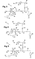
Figure 4 is a schematic diagram showing another embodiment of the invention comprising an optional back-flow circuit by-passing the feed valve; -
Figure 5 is a schematic diagram showing another embodiment of the invention comprising an arrangement for monitoring leakage in the apparatus. - On
Figure 1 is represented a part of an engine arrangement which can be used for powering a stationary machine, but which can also be fitted for example in a vehicle, such as an industrial truck, or in a machine such as a construction equipment machine. - The
engine arrangement 10 comprises anengine 12, such as a 6 cylinder in-line turbocharged diesel engine. Theengine 12 comprises anengine block 14, anintake manifold 16 and anexhaust manifold 18, plus numerous other components not represented on the figure. Theexhaust manifold 18 is part of anexhaust line 19 and collects the exhaust gases from the cylinders into at least oneexhaust pipe 20. Theexhaust line 19 may comprise many other components which are not shown on the figure, such as one or several turbines, an exhaust gas recirculation (EGR) system, an exhaust silencer, etc.. Onfigure 1 is represented an exhaustgas treatment device 22 which has the purpose of modifying the chemical composition of the exhaust gases in order to limit the amount of toxic substances which are susceptible to be emitted by the engine arrangement to the atmosphere through the exhaust system. The exhaust gas treatment device can be of many types, but it will be focused here on devices which necessitate the injection of a fluid in the exhaust gases to achieve the desired treatment of gases, the treatment being possibly only partial. Therefore, the engine arrangement is equipped with anapparatus 24 for injection of a fluid within theexhaust line 19. In the shown embodiment, the apparatus has aninjector 26 for injecting the fluid directly in theexhaust pipe 20, upstream of the treatment device. Nevertheless, the invention would also be applicable to systems where the fluid is injected within thedevice 22 itself, or downstream of the device. It could also be applicable to an apparatus for injecting the fluid within the engine itself, as it is known to inject such kind of fluid directly in the engine cylinder(s) for treating the gases generated by the combustion directly in the cylinder. In the latter case, the exhaust gas treatment device will be the cylinder itself. The exhaust line can be equipped with means to enhance the mixing of exhaust gases with the fluid injected byinjector 26. - The
treatment device 22 could be for example a diesel particulate filter (DPF) or a selective catalytic reduction (SCR) converter. In both cases, the fluid to be injected in the exhaust line is under liquid form, be it fuel or a water/urea solution. - In the following description, it will be considered the case where the apparatus is adapted to inject fuel upstream of a DPF treatment device.
- On
Figure 2 is depicted a basic embodiment of anapparatus 24 according to the invention. - First of all, the
apparatus 24 comprises an electromagnetically controlledinjector 26 which is fed from a source of fluid underpressure 28 through afluid conduit 30. The source of fluid underpressure 28 can be a dedicated system, especially when the fluid to be injected is specific to the treatment device, such as the water/urea solution which is to be injected upstream of a SCR catalytic converter. The source offluid 28 can also be shared with other components of the engine. For exemple, in the case of a DPF where the fluid to be injected is fuel, it would be of course advantageous to use a common pressurized source for the engine fuel injection system and for the apparatus according to the invention. For example, the common source of pressurized fuel could be a low pressure pump of the engine fuel injection system. The injector is adapted to inject fluid in a flow of exhaust gases within theexhaust pipe 20. - The apparatus also comprises a
feed valve 32 in the fluid conduit between said source of fluid and said injector for controlling the delivery of fluid. Thefeed valve 32 is provided mainly for safety reasons, in case a failure of the injector would result in it staying in its open position. With the safety valve, it is ensured that no fuel is injected in the exhaust line if it is not needed. The feed valve has therefore the function of a shut-off valve. Preferably, thefeed valve 32 is an electromagnetically controlled valve. - Although not shown on the drawings, the
injector 26 and the electromagnetically controlledfeed valve 32 are controlled by an electronic control unit (ECU), preferably by the same ECU which may in fact be common with a main engine fuel injection ECU. To inject fuel in the exhaust line, the ECU shall control both the feed valve and the injector to an open position so that the fuel under pressure is propelled into the exhaust pipe. - According to the invention, the
apparatus 24 also comprises apurge system 34 for purging at least theinjector 26, said purge system comprising agas conduit 36 connecting a source ofpressurized gas 38 to theinjector 26. The purge system is therefore an active system using a pressurized gas to remove any other fluid from theinjector 26. The purge system is therefore more efficient than a drain system where the pressure of the fluid itself is used to evacuate the fluid. - Preferably, the
gas conduit 36 is connected not to theinjector 26 itself, but to thefuel conduit 30 at ajunction 31. Indeed, this allows using a non-modified injector, not having a purge air port, and this allows purging at least part of thefuel conduit 30, especially the part which is the closest to the injector. That part of thefuel conduit 30 is prone to be quite close to the exhaust line and therefore to be subject to high temperatures. - The source of pressurized gas may be of different kinds. In the case of a commercial truck, it is well known to have a compressed air system where air is compressed and stored to perform a variety of functions, including the activation of the brakes, the pressurization of an air spring suspension, etc.... In such a case, it would of course be economical to use the same compressed air system as the source of pressurized gas.
- According to one aspect of the invention, the
purge system 34 is devoid of any controlled valve. This has of course the advantage of achieving a low cost design because it saves the cost of such a controlled valve and of the corresponding control circuitry. Indeed, even if an additional valve could be controlled by the same ECU as the injector, this it would inevitably increase the price of the ECU if it had to control another valve. - As shown on
figure 2 , thepurge system 34 comprises apressure limiter 40 which is located within the gas conduit between thepressurized gas source 38 and the junction with thefluid conduit 30. Preferably, the pressure limiter is chosen so that the pressure of gas flowing downstream of thelimiter 40 is lower than the pressure of fluid delivered by the source of fluid in the fluid conduit downstream of the feed valve. The purge system is also preferably equipped with acheck valve 42 downstream of thepressure limiter 40, for preventing backflow from thefluid conduit 30 towards thegas source 38. The pressure limiter can be embodied as a pressure regulator or any known equivalent to the man in the art. Thecheck valve 42 can be integrated within thepressure limiter 40. - For example, the pressure limiter is constructed as a conventional air pressure regulator. Alternatively, a check valve with an opening pressure greater than the difference between the gas pressure and the fluid pressure could be used.
- In the example shown, the low pressure pump which may be used as the pressurized
fluid source 28 may for example deliver fuel under a pressure which, depending on engine operating conditions, may vary between 2.5 and 6 bars. In such a case, thepressure limiter 40 will be chosen for example so that it will limit the downstream pressure at around 2 bars, plus or minus 0.3 bar. - Since the gas pressure regulated by the
limiter 40 is lower than the fluid pressure, whenever thefeed valve 32 is opened, the fluid pressure will force thecheck valve 42 to close, which will interrupt any communication between theinjector 26 and thegas source 38. Therefore, opening and closing of the injector will simply control the injection of fluid in the exhaust line. - To the contrary, if the
feed valve 32 is closed and theinjector 26 is opened, the fluid pressure in thefluid conduit 36 will automatically drop below the pressure regulated by thelimiter 40, so that the gas pressure will force thecheck valve 42 to open, letting pressurized gas flow in thefluid conduit 30 and in theinjector 26, which will achieve the goal of purging the fluid which had remained therein after thefeed valve 32 has been closed. - With the feed valve still closed, the
injector 26 can be controlled to be closed also, thereby interrupting the purging process. - As seen above, this new design of a purge system ensures that pressurized gas is automatically delivered by the purge system to the fluid conduit when the injector is open and when the feed valve is closed, and that no gas can be delivered by the purge system to the fluid conduit when the feed valve is opened, this without the need to have any controlled mechanism in the purge system.
- Thanks to the presence of the pressure limiter, and to the correct choice of its limiting pressure, the source of pressurized gas delivers gas under a pressure which can exceed the pressure of fluid delivered by the source of fluid in the main conduit downstream of the feed valve, while still performing the above procedures without having any controlled mechanism in the purge system.
- On
Figure 3 is shown a second embodiment of the invention wherein theapparatus 24 comprises an additionalnon-return valve 44 located in thefluid conduit 30 between thefeed valve 32 and thejunction 31 of the gas conduit with thefluid conduit 30 for preventing backflow towards thefeed valve 32. Preferably, the additionalnon-return valve 44 will be locate as close as possible to thejunction 31, so as to limit the portion of thefluid conduit 30 wherein gas will be trapped after the purge procedure: - On the other hand, it is then preferable to provide a
drain system 46 for draining the portion, or otherwise venting the pressure, of the fluid conduit between the feed valve and the non-return valve, as shown onFigure 3 . Indeed, depending on the pressure in the portion of thefluid conduit 30 downstream of thenon-return valve 44, and depending on the pressure drop across the non-return valve, some fluid may remain trapped between thefeed valve 32 andnon-return valve 44 when the former is closed. Due to thenon-return valve 44, this fluid cannot be actively purged by thepurge system 34. Therefore, to prevent any risk of over pressure in the intermediate portion of thefluid conduit 30 between thefeed valve 32 andnon-return valve 44, which can be the result of an increase in temperature of the fluid when the trapped fluid remains stagnant in that portion of theconduit 30, thedrain system 46 will allow some excess fluid to be returned to atank 54. In the embodiment shown, thedrain system 46 comprises adrain conduit 48 which is branched-off the intermediate portion of thefluid conduit 30. Aflow restriction 50 and arelief valve 52 are provided in thedrain conduit 48 to allow some fluid to be drained in case of excess pressure in the intermediate portion of fluid conduit. Preferably, theflow restriction 50 and therelief valve 52 will be calibrated so that, at the operating pressure of the fuel conduit when both thefeed valve 32 and theinjector 26 are opened, no fluid or little fluid will be drained through thedrain circuit 46. Apressure sensor 56 can also be provided in the intermediate portion of thefluid conduit 30 to monitor the fluid pressure therein. - On
Figure 4 , is shown another embodiment of the invention which is exactly similar to the embodiment ofFigure 3 , except that thedrain circuit 46 is replaced by a back-flow circuit 55 by-passing thefeed valve 32 and equipped with arelief valve 58 allowing flow only from the intermediate portion of thefluid conduit 30 towards thefluid pressure source 28. The back-flow circuit has a back flow-conduit 60 connected to thefluid conduit 30 both upstream and downstream of thefeed valve 32, and therelief valve 58 is located in that back-flow conduit 30 to prevent any forward flow through that back-flow conduit. The back flow circuit has here basically the same function as the drain circuit inFigure 3 . - On
Figure 5 is shown a further embodiment which is based on the example ofFigure 3 . In this embodiment, apressure sensor 59 is provided in thefuel conduit 30 downstream of thenon-return valve 44. Thepressure sensor 59 could also be located in thegas conduit 36 downstream ofcheck valve 42. The idea is here to be able to measure the pressure of fluid or of gas just upstream of theinjector 26. Also, in this embodiment, it is preferable to have aflow restrictor 60 in the gas conduit, for example between thepressure limiter 40 and thecheck valve 42, so that the pressure sensor. 59 is located downstream of theflow restrictor 60. The flow restrictor should have flow allowance (i.e. a diameter equivalence) which is as small as possible, while still being superior to the flow allowance of theinjector 26 when fully open. The flow restrictor can be a specific part in thepurge circuit 34, but it can in fact be thegas conduit 36 itself, or it can be integrated within the pressure limiter or within thecheck valve 42. - Thanks to the
flow restrictor 60 and to thepressure sensor 59, it will be possible to implement a monitoring process for detecting potential leakages occurring for example at theinjector 26. The main steps of the process would include: - a) controlling the
feed valve 32 and theinjector 30 to a closed position; - b) providing a known pressure within the
gas conduit 36; and - d) measuring the gas pressure downstream of the flow restricting means, for example through
pressure sensor 59; - e) comparing the pressure measured downstream of the flow restricting means to the known pressure provided within the gas conduit.
- In the context of a purge system equipped with a pressure limiter, the known pressure provided at step b) will be the pressure as limited or regulated by the
limiter 40. Therefore, in case there would be a leakage downstream of the restrictor 60, such as theinjector 26 remaining open despite the controlling order to be closed, or such as thefluid conduit 30 being punctured or broken, the pressure measured bysensor 59 will be considerably lower than the pressure which is supposed to be provided. Indeed, theflow restrictor 60 will impede any pressure build-up, except for leakages which would be very small in terms of flow compared to the flow allowed through the restrictor. - This process to monitor leakages is very cost effective because it requires only limited additional hardware. Also very advantageous is the fact that the detection process is carried out by using compressed gas, and preferably compressed air, and it is therefore innocuous to the atmosphere in case of leakage. Of course, the process and the associated hardware can be implemented within all the above described embodiments of the invention.
- The
pressure sensor 59 ofFigure 5 , or thepressure sensor 56 ofFigures 3 and 4 could also be used to perform the following leak test, with theinjector 26 remaining closed. Thefeed valve 32 can be opened to pressurize theconduit 30 to the fluid supply pressure. Thefeed valve 32 is then closed and the resulting pressure decay is monitored on the pressure sensor to detect a leak. - Therefore, the apparatus according to the invention is cheap, reliable, and can be easily retrofit. Indeed, a retrofit kit can comprise either a complete apparatus for injection of a fluid for an exhaust gases treatment device of an internal combustion engine arrangement, but it can also consist in a kit comprising only the purge system. The retrofit purge system could then be mounted on any apparatus already comprising an electromagnetically controlled fluid injector fed from a source of fluid under pressure through a fluid conduit, and a feed valve in the fluid conduit between said source of fluid and said injector for controlling the delivery of fluid.
- Such retrofit purge system kit would then comprise:
- a
gas conduit 36 for connecting a source ofpressurized gas 38 to the fuel conduit;- a
pressure limiter 40 to be fitted within saidgas conduit 36; and - a
check valve 42 downstream of saidpressure limiter 40 for preventing backflow from thefluid conduit 30 towards thegas source 38, and wherein - the pressure limited by said
pressure limiter 40 is lower than the pressure of fluid delivered by the source of fluid in the fluid conduit downstream of the feed valve.
- a
- Such a retrofit kit is easy to install and would not necessitate any additional electronic hardware or any additional electronic connection. It may only be necessary to update the computer program running the injector.
Claims (14)
- An apparatus for injection of a fluid for an exhaust gases treatment device (22) of an internal combustion engine arrangement, said apparatus (24) including:- a fluid injector (26) fed from a source (28) of fluid under pressure through a fluid conduit (30), and adapted to inject fluid in a flow of exhaust gases within an exhaust line (19) of said engine arrangement;- a feed valve (32) in the fluid conduit (30) between said source (28) of fluid and said injector (26) for controlling the delivery of fluid;- a purge system (34) for purging the injector (26), said purge system comprising a gas conduit (36) connecting a source (38) of pressurized gas to the fluid conduit (30), a pressure limiter (40) within said gas conduit (36), a check valve (42) downstream of said pressure limiter for preventing backflow from the fluid conduit (30) towards the gas source (38);characterized in that :- said fluid injector is electromagnetically controlled, and in that- the pressure limited by said pressure limiter (40) is lower than the pressure of fluid delivered by the source (28) of fluid in the fluid conduit (30) downstream of the feed valve (32).
- An apparatus according to claim 1, characterized in that the source (38) of pressurized gas delivers gas under a pressure which can exceed the pressure of fluid delivered by the source (28) of fluid in the fluid conduit (30) downstream of the feed valve (32).
- An apparatus according to claims I or 2, characterized in that the purge system (34) is devoid of any controlled valve.
- An apparatus according to any preceding claim, characterized in that pressurized gas is automatically delivered by the purge system (34) to the fluid conduit (30) when the injector (26) is open and when the feed valve (32) is closed.
- An apparatus according to any preceding claim, characterized in that no gas can be delivered by the purge system (34) to the fluid conduit (30) when the feed valve (32) is opened.
- An apparatus according to any preceding claim, characterized in that the check valve (42) is integrated within the pressure limiter (40).
- An apparatus according to any preceding claim, characterized in that the apparatus further comprises a non-return valve (44) in the fluid conduit (30) between the feed valve (32) and the junction (31) of the gas conduit (36) with the fluid conduit (30) for preventing backflow towards the feed valve (32).
- An apparatus according to claim 7, characterized in that the apparatus further comprises a drain system (46) for draining the portion of the fluid conduit (30) between the feed valve (32) and the non-return valve (44).
- An apparatus according to claims 7 or 8, characterized in that the apparatus comprises a back-flow circuit (55) by-passing the feed valve (32) and equipped with a relief valve (58) allowing flow only from the fluid conduit (30) towards the fluid pressure source (28).
- An apparatus according to any preceding claim, characterized in that the apparatus (24) comprises a flow restrictor (60) in the gas conduit (36) and a pressure sensor (59) downstream of the flow restrictor (60).
- An apparatus according to claim 10, characterized in that the pressure sensor (59) is located in the fluid conduit (30).
- An apparatus according to any of claims 1-11, characterized in that the feed valve (32) is an electromagnetically controlled valve.
- An engine arrangement, characterized in that it is equipped with an apparatus (24) according to any of the preceding claims.
- A kit for retrofitting a purge system (34) on an apparatus (24) for injection of a fluid for an exhaust gases treatment device of an internal combustion engine arrangement, said apparatus including:- an electromagnetically controlled fluid injector (26) fed from a source (28) of fluid under pressure through a fluid conduit (30), and adapted to inject fluid in a flow of exhaust gases within an exhaust line of said engine arrangement, upstream of said treatment device;- a feed valve (32) in the fluid conduit between said source (28) of fluid and said injector for controlling the delivery of fluid;
characterized in that the kit comprises- a gas conduit (36) for connecting a source (38) of pressurized gas to the fuel conduit (30);- a pressure limiter (40) to be fitted within said gas conduit (36); and- a check valve (42) to be fitted downstream of said pressure limiter (40) for preventing backflow from the fluid conduit (30) towards the gas source (38), and wherein- the pressure limited by said pressure limiter (40) is lower than the pressure of fluid delivered by the source of fluid (28) in the fluid conduit (30) downstream of the feed valve (32).
Applications Claiming Priority (1)
| Application Number | Priority Date | Filing Date | Title |
|---|---|---|---|
| PCT/IB2007/004422 WO2009081228A1 (en) | 2007-12-21 | 2007-12-21 | Apparatus and method for injection of a fluid for an exhaust gases treatment device |
Publications (2)
| Publication Number | Publication Date |
|---|---|
| EP2235336A1 EP2235336A1 (en) | 2010-10-06 |
| EP2235336B1 true EP2235336B1 (en) | 2011-12-21 |
Family
ID=39712173
Family Applications (1)
| Application Number | Title | Priority Date | Filing Date |
|---|---|---|---|
| EP07870453A Active EP2235336B1 (en) | 2007-12-21 | 2007-12-21 | Apparatus for injection of a fluid for an exhaust gases treatment device |
Country Status (6)
| Country | Link |
|---|---|
| US (1) | US8359834B2 (en) |
| EP (1) | EP2235336B1 (en) |
| JP (1) | JP5118755B2 (en) |
| CN (1) | CN101903624B (en) |
| AT (1) | ATE538288T1 (en) |
| WO (1) | WO2009081228A1 (en) |
Families Citing this family (20)
| Publication number | Priority date | Publication date | Assignee | Title |
|---|---|---|---|---|
| ES2541499T3 (en) * | 2007-08-20 | 2015-07-21 | Parker-Hannifin Corporation | Diesel dosing system for regeneration of the active filtrate of diesel particles |
| CA2721439C (en) * | 2008-04-15 | 2016-01-12 | G.W. Lisk Company, Inc. | System for purging a device |
| US20100083940A1 (en) * | 2008-10-04 | 2010-04-08 | Woodford Leon Vrazel | Cryogenic air cooler for improving power and fuel efficiency of a motor vehicle internal combustion engine |
| JP5656280B2 (en) * | 2009-12-11 | 2015-01-21 | ボルボ パワートレイン アーベーVolvo Powertrain Ab | Post-treatment fuel addition equipment |
| SE535143C2 (en) * | 2010-05-28 | 2012-04-24 | Scania Cv Ab | Method and system for testing an injection system in a gasification process or a combustion process |
| SE536316C2 (en) * | 2010-06-21 | 2013-08-20 | Scania Cv Ab | Method and apparatus for removing fuel from a metering unit of an HC metering system |
| DE102010044399A1 (en) | 2010-09-04 | 2012-03-08 | Deutz Ag | pipe |
| DE102011017028A1 (en) * | 2011-04-14 | 2012-10-18 | Deutz Aktiengesellschaft | Absteuervorrichtung |
| WO2014091864A1 (en) * | 2012-12-10 | 2014-06-19 | ボルボ ラストバグナー アクチエボラグ | Exhaust pipe fuel injector |
| EP3077636B1 (en) * | 2013-12-06 | 2018-08-15 | Volvo Truck Corporation | A fuel system for an internal combustion engine arrangement |
| US10473014B2 (en) * | 2013-12-23 | 2019-11-12 | Baohua Qi | Low pressure atomizing injector |
| US9140166B1 (en) | 2014-04-04 | 2015-09-22 | Caterpillar Inc. | Reductant dosing system |
| US9387437B2 (en) | 2014-05-21 | 2016-07-12 | Caterpillar Inc. | Reductant supply system |
| US10632421B2 (en) | 2014-10-28 | 2020-04-28 | Volvo Truck Corporation | Electrostatic fluid injection system |
| DE102016119713B3 (en) * | 2016-10-17 | 2018-03-08 | Avl Emission Test Systems Gmbh | Gas supply unit for an exhaust gas analysis unit for measuring exhaust gases of internal combustion engines |
| JP6895077B2 (en) * | 2017-09-26 | 2021-06-30 | 株式会社ノーリツ | Combustion device |
| EP3494926A1 (en) | 2017-12-05 | 2019-06-12 | Repuls Lichtmedizinteckhnik GmbH | Implant with reservoir |
| US11326492B2 (en) * | 2018-11-09 | 2022-05-10 | Rotex Automation Limited | Hydrocarbon dosing system |
| WO2020123304A1 (en) * | 2018-12-14 | 2020-06-18 | Cummins Filtration Ip, Inc. | Diesel fuel dosing module for regeneration of diesel particulate filters with continuous purging |
| US12054924B2 (en) | 2020-05-28 | 2024-08-06 | Zurn Water, Llc | Smart and connected backflow preventer assembly |
Family Cites Families (11)
| Publication number | Priority date | Publication date | Assignee | Title |
|---|---|---|---|---|
| DE19653405C2 (en) | 1996-12-20 | 1999-06-10 | Bosch Gmbh Robert | Mixture dispenser |
| JP3473583B2 (en) * | 2000-07-24 | 2003-12-08 | トヨタ自動車株式会社 | Exhaust gas purification device for internal combustion engine |
| JP2004308595A (en) * | 2003-04-09 | 2004-11-04 | Nissan Motor Co Ltd | Evaporative fuel processing device and diagnostic device for the device |
| JP4152833B2 (en) * | 2003-07-30 | 2008-09-17 | 日産ディーゼル工業株式会社 | Engine exhaust purification system |
| JP4389609B2 (en) * | 2004-03-03 | 2009-12-24 | トヨタ自動車株式会社 | Exhaust gas purification device for internal combustion engine |
| JP2005248823A (en) * | 2004-03-04 | 2005-09-15 | Hino Motors Ltd | Reducing agent supply device |
| JP4569954B2 (en) * | 2004-11-01 | 2010-10-27 | バブコック日立株式会社 | Exhaust gas denitration apparatus and method |
| EP1676628B1 (en) * | 2004-12-30 | 2009-10-07 | Grundfos NoNox a/s | Dosing pump unit |
| DE502004005576D1 (en) * | 2004-12-30 | 2008-01-03 | Grundfos Nonox As | Device for generating a reducing agent-air mixture |
| SE529591C2 (en) | 2006-02-08 | 2007-09-25 | Stt Emtec Ab | injection device |
| US20080295492A1 (en) * | 2007-05-31 | 2008-12-04 | Caterpillar Inc. | Injector cleaning system based on pressure decay |
-
2007
- 2007-12-21 WO PCT/IB2007/004422 patent/WO2009081228A1/en not_active Ceased
- 2007-12-21 CN CN2007801020335A patent/CN101903624B/en active Active
- 2007-12-21 EP EP07870453A patent/EP2235336B1/en active Active
- 2007-12-21 US US12/809,405 patent/US8359834B2/en active Active
- 2007-12-21 AT AT07870453T patent/ATE538288T1/en active
- 2007-12-21 JP JP2010538929A patent/JP5118755B2/en not_active Expired - Fee Related
Also Published As
| Publication number | Publication date |
|---|---|
| EP2235336A1 (en) | 2010-10-06 |
| ATE538288T1 (en) | 2012-01-15 |
| WO2009081228A1 (en) | 2009-07-02 |
| JP2011508132A (en) | 2011-03-10 |
| US8359834B2 (en) | 2013-01-29 |
| CN101903624A (en) | 2010-12-01 |
| JP5118755B2 (en) | 2013-01-16 |
| CN101903624B (en) | 2012-12-12 |
| US20110016854A1 (en) | 2011-01-27 |
Similar Documents
| Publication | Publication Date | Title |
|---|---|---|
| US8359834B2 (en) | Apparatus and method for injection of a fluid for an exhaust gases treatment device | |
| CN102022168B (en) | Method of monitoring function of selective catalytic reaction (SCR) catalyst | |
| EP2034148B1 (en) | Engine exhaust emission control device | |
| EP2860368B1 (en) | Reagent doser diagnostic system and method | |
| RU2645123C2 (en) | Method and device for operating the sensor for determining the exhaust gas components, in particular of a motor vehicle | |
| WO2008020935A1 (en) | Fuel supply component purging system | |
| US20140331645A1 (en) | System and Method for Injector Fault Remediation | |
| JP5049951B2 (en) | Exhaust aftertreatment device | |
| US20150240683A1 (en) | Reductant supply system | |
| US10337385B2 (en) | Injector deposit detection for SCR injection system | |
| US8596043B2 (en) | Diesel dosing system relief of trapped volume fluid pressure at shutdown | |
| WO2008079190A1 (en) | Fuel supply component cleaning system | |
| US11401849B2 (en) | Internal combustion engine exhaust purification device | |
| US11873751B2 (en) | System and method for monitoring location of diesel exhaust fluid in a dosing system | |
| WO2008020936A1 (en) | Fuel supply component cleaning system | |
| US8086389B2 (en) | Control apparatus for controlling both fuel injection system and exhaust gas cleaning system | |
| KR102193647B1 (en) | Urea supply unit for exhaust gas cleaning system | |
| EP1999348B1 (en) | Diesel exhaust dosing structure | |
| US20160222859A1 (en) | Method and system for detecting malfunctioning of fluid tank of machine | |
| JP6556531B2 (en) | Abnormality judgment device for additive supply system | |
| JP2007315313A (en) | Exhaust emission control device of internal combustion engine | |
| CN210289879U (en) | Fuel injection device of DPF regeneration system | |
| CN115539175B (en) | Device and method for detecting pressure of post-treatment liquid supply pipeline | |
| US20180223710A1 (en) | Fuel supply device for engine injection and exhaust-gas aftertreatment | |
| WO2025109002A1 (en) | Method of operating a reductant injection system |
Legal Events
| Date | Code | Title | Description |
|---|---|---|---|
| PUAI | Public reference made under article 153(3) epc to a published international application that has entered the european phase |
Free format text: ORIGINAL CODE: 0009012 |
|
| 17P | Request for examination filed |
Effective date: 20100721 |
|
| AK | Designated contracting states |
Kind code of ref document: A1 Designated state(s): AT BE BG CH CY CZ DE DK EE ES FI FR GB GR HU IE IS IT LI LT LU LV MC MT NL PL PT RO SE SI SK TR |
|
| AX | Request for extension of the european patent |
Extension state: AL BA HR MK RS |
|
| RTI1 | Title (correction) |
Free format text: APPARATUS FOR INJECTION OF A FLUID FOR AN EXHAUST GASES TREATMENT DEVICE |
|
| 17Q | First examination report despatched |
Effective date: 20110301 |
|
| DAX | Request for extension of the european patent (deleted) | ||
| GRAP | Despatch of communication of intention to grant a patent |
Free format text: ORIGINAL CODE: EPIDOSNIGR1 |
|
| GRAS | Grant fee paid |
Free format text: ORIGINAL CODE: EPIDOSNIGR3 |
|
| GRAA | (expected) grant |
Free format text: ORIGINAL CODE: 0009210 |
|
| AK | Designated contracting states |
Kind code of ref document: B1 Designated state(s): AT BE BG CH CY CZ DE DK EE ES FI FR GB GR HU IE IS IT LI LT LU LV MC MT NL PL PT RO SE SI SK TR |
|
| REG | Reference to a national code |
Ref country code: GB Ref legal event code: FG4D |
|
| REG | Reference to a national code |
Ref country code: CH Ref legal event code: EP |
|
| REG | Reference to a national code |
Ref country code: AT Ref legal event code: REF Ref document number: 538288 Country of ref document: AT Kind code of ref document: T Effective date: 20120115 |
|
| REG | Reference to a national code |
Ref country code: IE Ref legal event code: FG4D |
|
| REG | Reference to a national code |
Ref country code: DE Ref legal event code: R096 Ref document number: 602007019594 Country of ref document: DE Effective date: 20120223 |
|
| REG | Reference to a national code |
Ref country code: NL Ref legal event code: VDEP Effective date: 20111221 |
|
| PG25 | Lapsed in a contracting state [announced via postgrant information from national office to epo] |
Ref country code: LT Free format text: LAPSE BECAUSE OF FAILURE TO SUBMIT A TRANSLATION OF THE DESCRIPTION OR TO PAY THE FEE WITHIN THE PRESCRIBED TIME-LIMIT Effective date: 20111221 |
|
| LTIE | Lt: invalidation of european patent or patent extension |
Effective date: 20111221 |
|
| PG25 | Lapsed in a contracting state [announced via postgrant information from national office to epo] |
Ref country code: SE Free format text: LAPSE BECAUSE OF FAILURE TO SUBMIT A TRANSLATION OF THE DESCRIPTION OR TO PAY THE FEE WITHIN THE PRESCRIBED TIME-LIMIT Effective date: 20111221 Ref country code: NL Free format text: LAPSE BECAUSE OF FAILURE TO SUBMIT A TRANSLATION OF THE DESCRIPTION OR TO PAY THE FEE WITHIN THE PRESCRIBED TIME-LIMIT Effective date: 20111221 Ref country code: GR Free format text: LAPSE BECAUSE OF FAILURE TO SUBMIT A TRANSLATION OF THE DESCRIPTION OR TO PAY THE FEE WITHIN THE PRESCRIBED TIME-LIMIT Effective date: 20120322 Ref country code: LV Free format text: LAPSE BECAUSE OF FAILURE TO SUBMIT A TRANSLATION OF THE DESCRIPTION OR TO PAY THE FEE WITHIN THE PRESCRIBED TIME-LIMIT Effective date: 20111221 Ref country code: SI Free format text: LAPSE BECAUSE OF FAILURE TO SUBMIT A TRANSLATION OF THE DESCRIPTION OR TO PAY THE FEE WITHIN THE PRESCRIBED TIME-LIMIT Effective date: 20111221 |
|
| PG25 | Lapsed in a contracting state [announced via postgrant information from national office to epo] |
Ref country code: CY Free format text: LAPSE BECAUSE OF FAILURE TO SUBMIT A TRANSLATION OF THE DESCRIPTION OR TO PAY THE FEE WITHIN THE PRESCRIBED TIME-LIMIT Effective date: 20111221 Ref country code: BE Free format text: LAPSE BECAUSE OF FAILURE TO SUBMIT A TRANSLATION OF THE DESCRIPTION OR TO PAY THE FEE WITHIN THE PRESCRIBED TIME-LIMIT Effective date: 20111221 |
|
| PG25 | Lapsed in a contracting state [announced via postgrant information from national office to epo] |
Ref country code: SK Free format text: LAPSE BECAUSE OF FAILURE TO SUBMIT A TRANSLATION OF THE DESCRIPTION OR TO PAY THE FEE WITHIN THE PRESCRIBED TIME-LIMIT Effective date: 20111221 Ref country code: CZ Free format text: LAPSE BECAUSE OF FAILURE TO SUBMIT A TRANSLATION OF THE DESCRIPTION OR TO PAY THE FEE WITHIN THE PRESCRIBED TIME-LIMIT Effective date: 20111221 Ref country code: EE Free format text: LAPSE BECAUSE OF FAILURE TO SUBMIT A TRANSLATION OF THE DESCRIPTION OR TO PAY THE FEE WITHIN THE PRESCRIBED TIME-LIMIT Effective date: 20111221 Ref country code: MC Free format text: LAPSE BECAUSE OF NON-PAYMENT OF DUE FEES Effective date: 20111231 Ref country code: IS Free format text: LAPSE BECAUSE OF FAILURE TO SUBMIT A TRANSLATION OF THE DESCRIPTION OR TO PAY THE FEE WITHIN THE PRESCRIBED TIME-LIMIT Effective date: 20120421 Ref country code: BG Free format text: LAPSE BECAUSE OF FAILURE TO SUBMIT A TRANSLATION OF THE DESCRIPTION OR TO PAY THE FEE WITHIN THE PRESCRIBED TIME-LIMIT Effective date: 20120321 |
|
| REG | Reference to a national code |
Ref country code: CH Ref legal event code: PL |
|
| PG25 | Lapsed in a contracting state [announced via postgrant information from national office to epo] |
Ref country code: RO Free format text: LAPSE BECAUSE OF FAILURE TO SUBMIT A TRANSLATION OF THE DESCRIPTION OR TO PAY THE FEE WITHIN THE PRESCRIBED TIME-LIMIT Effective date: 20111221 Ref country code: PT Free format text: LAPSE BECAUSE OF FAILURE TO SUBMIT A TRANSLATION OF THE DESCRIPTION OR TO PAY THE FEE WITHIN THE PRESCRIBED TIME-LIMIT Effective date: 20120423 Ref country code: PL Free format text: LAPSE BECAUSE OF FAILURE TO SUBMIT A TRANSLATION OF THE DESCRIPTION OR TO PAY THE FEE WITHIN THE PRESCRIBED TIME-LIMIT Effective date: 20111221 |
|
| REG | Reference to a national code |
Ref country code: AT Ref legal event code: MK05 Ref document number: 538288 Country of ref document: AT Kind code of ref document: T Effective date: 20111221 |
|
| REG | Reference to a national code |
Ref country code: IE Ref legal event code: MM4A |
|
| PLBE | No opposition filed within time limit |
Free format text: ORIGINAL CODE: 0009261 |
|
| STAA | Information on the status of an ep patent application or granted ep patent |
Free format text: STATUS: NO OPPOSITION FILED WITHIN TIME LIMIT |
|
| PG25 | Lapsed in a contracting state [announced via postgrant information from national office to epo] |
Ref country code: CH Free format text: LAPSE BECAUSE OF NON-PAYMENT OF DUE FEES Effective date: 20111231 Ref country code: LI Free format text: LAPSE BECAUSE OF NON-PAYMENT OF DUE FEES Effective date: 20111231 Ref country code: DK Free format text: LAPSE BECAUSE OF FAILURE TO SUBMIT A TRANSLATION OF THE DESCRIPTION OR TO PAY THE FEE WITHIN THE PRESCRIBED TIME-LIMIT Effective date: 20111221 Ref country code: IE Free format text: LAPSE BECAUSE OF NON-PAYMENT OF DUE FEES Effective date: 20111221 |
|
| 26N | No opposition filed |
Effective date: 20120924 |
|
| GBPC | Gb: european patent ceased through non-payment of renewal fee |
Effective date: 20120321 |
|
| PG25 | Lapsed in a contracting state [announced via postgrant information from national office to epo] |
Ref country code: IT Free format text: LAPSE BECAUSE OF FAILURE TO SUBMIT A TRANSLATION OF THE DESCRIPTION OR TO PAY THE FEE WITHIN THE PRESCRIBED TIME-LIMIT Effective date: 20111221 |
|
| REG | Reference to a national code |
Ref country code: DE Ref legal event code: R097 Ref document number: 602007019594 Country of ref document: DE Effective date: 20120924 |
|
| PG25 | Lapsed in a contracting state [announced via postgrant information from national office to epo] |
Ref country code: GB Free format text: LAPSE BECAUSE OF NON-PAYMENT OF DUE FEES Effective date: 20120321 Ref country code: AT Free format text: LAPSE BECAUSE OF FAILURE TO SUBMIT A TRANSLATION OF THE DESCRIPTION OR TO PAY THE FEE WITHIN THE PRESCRIBED TIME-LIMIT Effective date: 20111221 |
|
| PG25 | Lapsed in a contracting state [announced via postgrant information from national office to epo] |
Ref country code: MT Free format text: LAPSE BECAUSE OF FAILURE TO SUBMIT A TRANSLATION OF THE DESCRIPTION OR TO PAY THE FEE WITHIN THE PRESCRIBED TIME-LIMIT Effective date: 20111221 |
|
| PG25 | Lapsed in a contracting state [announced via postgrant information from national office to epo] |
Ref country code: ES Free format text: LAPSE BECAUSE OF FAILURE TO SUBMIT A TRANSLATION OF THE DESCRIPTION OR TO PAY THE FEE WITHIN THE PRESCRIBED TIME-LIMIT Effective date: 20120401 |
|
| PG25 | Lapsed in a contracting state [announced via postgrant information from national office to epo] |
Ref country code: LU Free format text: LAPSE BECAUSE OF NON-PAYMENT OF DUE FEES Effective date: 20111221 |
|
| PG25 | Lapsed in a contracting state [announced via postgrant information from national office to epo] |
Ref country code: FI Free format text: LAPSE BECAUSE OF FAILURE TO SUBMIT A TRANSLATION OF THE DESCRIPTION OR TO PAY THE FEE WITHIN THE PRESCRIBED TIME-LIMIT Effective date: 20111221 |
|
| PG25 | Lapsed in a contracting state [announced via postgrant information from national office to epo] |
Ref country code: TR Free format text: LAPSE BECAUSE OF FAILURE TO SUBMIT A TRANSLATION OF THE DESCRIPTION OR TO PAY THE FEE WITHIN THE PRESCRIBED TIME-LIMIT Effective date: 20111221 |
|
| PG25 | Lapsed in a contracting state [announced via postgrant information from national office to epo] |
Ref country code: HU Free format text: LAPSE BECAUSE OF FAILURE TO SUBMIT A TRANSLATION OF THE DESCRIPTION OR TO PAY THE FEE WITHIN THE PRESCRIBED TIME-LIMIT Effective date: 20111221 |
|
| REG | Reference to a national code |
Ref country code: DE Ref legal event code: R082 Ref document number: 602007019594 Country of ref document: DE Representative=s name: V. FUENER EBBINGHAUS FINCK HANO, DE |
|
| REG | Reference to a national code |
Ref country code: DE Ref legal event code: R081 Ref document number: 602007019594 Country of ref document: DE Owner name: VOLVO TRUCK CORP., SE Free format text: FORMER OWNER: RENAULT TRUCKS, SAINT PRIEST, FR Effective date: 20141219 Ref country code: DE Ref legal event code: R082 Ref document number: 602007019594 Country of ref document: DE Representative=s name: V. FUENER EBBINGHAUS FINCK HANO, DE Effective date: 20141219 |
|
| REG | Reference to a national code |
Ref country code: FR Ref legal event code: TP Owner name: VOLVO LASTVAGNAR AKTIEBOLAG, SE Effective date: 20150209 |
|
| REG | Reference to a national code |
Ref country code: FR Ref legal event code: PLFP Year of fee payment: 9 |
|
| REG | Reference to a national code |
Ref country code: FR Ref legal event code: PLFP Year of fee payment: 10 |
|
| REG | Reference to a national code |
Ref country code: FR Ref legal event code: PLFP Year of fee payment: 11 |
|
| PGFP | Annual fee paid to national office [announced via postgrant information from national office to epo] |
Ref country code: FR Payment date: 20251223 Year of fee payment: 19 |
|
| PGFP | Annual fee paid to national office [announced via postgrant information from national office to epo] |
Ref country code: DE Payment date: 20251229 Year of fee payment: 19 |