EP2234279A1 - Pulse control of radio transmission - Google Patents
Pulse control of radio transmission Download PDFInfo
- Publication number
- EP2234279A1 EP2234279A1 EP09156015A EP09156015A EP2234279A1 EP 2234279 A1 EP2234279 A1 EP 2234279A1 EP 09156015 A EP09156015 A EP 09156015A EP 09156015 A EP09156015 A EP 09156015A EP 2234279 A1 EP2234279 A1 EP 2234279A1
- Authority
- EP
- European Patent Office
- Prior art keywords
- radio frequency
- waveform generator
- pulses
- radio
- generator
- Prior art date
- Legal status (The legal status is an assumption and is not a legal conclusion. Google has not performed a legal analysis and makes no representation as to the accuracy of the status listed.)
- Granted
Links
Images


Classifications
-
- G—PHYSICS
- G06—COMPUTING OR CALCULATING; COUNTING
- G06K—GRAPHICAL DATA READING; PRESENTATION OF DATA; RECORD CARRIERS; HANDLING RECORD CARRIERS
- G06K7/00—Methods or arrangements for sensing record carriers, e.g. for reading patterns
- G06K7/10—Methods or arrangements for sensing record carriers, e.g. for reading patterns by electromagnetic radiation, e.g. optical sensing; by corpuscular radiation
- G06K7/10009—Methods or arrangements for sensing record carriers, e.g. for reading patterns by electromagnetic radiation, e.g. optical sensing; by corpuscular radiation sensing by radiation using wavelengths larger than 0.1 mm, e.g. radio-waves or microwaves
- G06K7/10297—Methods or arrangements for sensing record carriers, e.g. for reading patterns by electromagnetic radiation, e.g. optical sensing; by corpuscular radiation sensing by radiation using wavelengths larger than 0.1 mm, e.g. radio-waves or microwaves arrangements for handling protocols designed for non-contact record carriers such as RFIDs NFCs, e.g. ISO/IEC 14443 and 18092
- G06K7/10306—Methods or arrangements for sensing record carriers, e.g. for reading patterns by electromagnetic radiation, e.g. optical sensing; by corpuscular radiation sensing by radiation using wavelengths larger than 0.1 mm, e.g. radio-waves or microwaves arrangements for handling protocols designed for non-contact record carriers such as RFIDs NFCs, e.g. ISO/IEC 14443 and 18092 ultra wide band
-
- H—ELECTRICITY
- H04—ELECTRIC COMMUNICATION TECHNIQUE
- H04B—TRANSMISSION
- H04B1/00—Details of transmission systems, not covered by a single one of groups H04B3/00 - H04B13/00; Details of transmission systems not characterised by the medium used for transmission
- H04B1/69—Spread spectrum techniques
- H04B1/7163—Spread spectrum techniques using impulse radio
- H04B1/717—Pulse-related aspects
- H04B1/7174—Pulse generation
Definitions
- the present invention generally relates to pulse control of radio transmission.
- the invention relates particularly, though not exclusively, to spectral shaping of impulse ultra-wide band based radio frequency identification systems.
- Short range communications such as near field communication and radio frequency identity (RFID) have been developed to provide tags that can be remotely read over a distance of some meters.
- RFID tags are traditionally used in logistics. For instance, paper rolls of a paper mill have been equipped with RFID tags so that each roll is identifiable all the way from packing to consumption.
- the near field communication technologies provide a means to transfer information, such as, for example an identity code.
- I-UWB Impulse ultra-wide band
- a data symbol is represented by one or more radio symbols in subsequent radio frames i.e. which frames are in practice subsequent periods.
- each frame is used to transmit a radio pulse as an indication of a data symbol "1" and not used to transmit a radio pulse as an indication of a data symbol "0".
- such a transmission scheme may suffer from a poor transmission spectrum envelope if the transmitted pulse sequence is not designed carefully.
- Radio transmissions are regulated so that all transmissions have to fit into a regulatory power spectral density mask that may be simplified as a rectangle in a frequency domain representation of radio power.
- a regulatory power spectral density mask that may be simplified as a rectangle in a frequency domain representation of radio power.
- I-UWB it is a common problem that when a pulse stream is radiated by an antenna, some spikes (with the period of pulse repetition frequency) in frequency domain may occur if the pulses are regularly spaced in time domain. This may exceed the mean or peak power mask allowed by regulation. Time hopping and amplitude or pulse-polarity coding have been used to cope with this issue.
- Pseudo-randomized time-hopping sequences are used in some prior-known implementations to decrease the periodicity of transmitted I-UWB pulse stream and to reduce power spikes from a frequency spectrum presentation of antenna power.
- Time-hopping sequences are also used as a multiple-access method by using different time-hopping codes for different users.
- pulses are timed to different parts of subsequent pulse repletion periods, which translates into a need of higher timing resolution.
- the communication based on pseudo-randomized time-hopping pulse streams requires relatively high frequency timing references, which unfortunately results in growing technical demands and more expensive construction.
- time-hoping necessitates that the receiver and the transmitter are somehow made aware of a common time-hopping scheme and of the timing of operation within the time-hopping scheme.
- Polarity coding of transmitted pulses is also known from I-UWB in general.
- the pulses that are sent have polarities that are differentiated by 180 degrees in a pseudo-random manner.
- the polarity coding needs further equipment in the transmitter to control the phase of radio transmission in the desired manner. Such further equipment comes with a cost of added price and power consumption, both of which are particularly inconvenient in RFID applications.
- an apparatus comprising:
- the different phases of the pulses may be freely selected without any discrete steps. Alternatively, the different phases may be selected with at least three different steps.
- the apparatus may further comprises an antenna configured to radiate the radio frequency pulses and the waveform generator is further configured to receive noise signals from the antenna when started and to responsively establish random phase radio frequency pulses.
- the apparatus may be configured to restart the waveform generator between shaping of subsequent pulses by the pulse generator.
- the apparatus may comprise for restarting the waveform generator a switch; a power ramp unit; or a gain controllable element with which the waveform generator may be started on beginning of the forming of a pulse by the pulse generator.
- the waveform generator may comprise a super-regenerative oscillator.
- the waveform generator and pulse generator may be configured to apply a time-hopping scheme such that pulses of adjacent frames may have different time offsets.
- the waveform generator may further be configured to alternate the center frequency of the radio frequency signal.
- the alternating may comprise changes scaled to alternate the antenna radiated radio signals within the spectral density mask.
- the alternating may comprise changes scaled to cause frequency hopping between different frequency bands with a frequency change substantially larger than that covered by the spectral density mask.
- the pulse generator may be configured to randomize the phase of the radio frequency pulses.
- the pulse generator may be configured to randomize the phase of the radio frequency pulses by varying the timing of producing the radio frequency pulse in relation to the timing of the waveform generator.
- the apparatus may further comprise a directional element configured to pass the radio frequency pulses towards an antenna and to inhibit entry of electric signals from the antenna to the waveform generator.
- the apparatus may further be configured to inject controlled noise to the waveform generator from an electric component comprised by the apparatus or accessible by the apparatus, which electric component is further configured to operate in another function in addition to injecting controlled noise to the waveform generator.
- the pulse generator may comprise a timing signal generator configured to produce a quench signal which controls the generation of pulses by activating and damping oscillations by the waveform generator.
- the apparatus may further comprise a receiver configured to receive impulse ultra-wide band radio communication signals.
- the receiver may be configured to use the antenna and the waveform generator to demodulate radio signals received by the antenna.
- the receiver may further comprise a correlator circuitry configured to test presence of impulse ultra-wide band radio pulses at given periods of time.
- the receiver may further be configured to use the timing signal generator to control the correlator circuitry.
- an apparatus comprising:
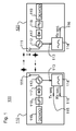
- Fig. 1 shows a schematic drawing of a system 100 according to an embodiment of the invention.
- the system comprises an impulse ultra-wide band (I-UWB) transmitter unit 110 that in this embodiment is a transceiver i.e. that is also capable of receiving information.
- the transmitter unit 110 comprises an antenna 111 and an oscillator 112 connected to the antenna, the oscillator comprising a pulse control input 113 connected to a quench signal source 114.
- the quench signal source 114 comprises a transmission activation signal input 115 and a reception activation signal input 116.
- the system 100 further comprises in a series a radio frequency (RF) detector 117, a low pass filter 118 and a demodulator 119.
- the RF detector 117 is connected to the oscillator 112.
- RF radio frequency
- the quench signal source 114 may be configured to operate as a pulse generator that has a transmission sequence input 115 and a reception sequence input 116.
- the sequence input 115 and/or the reception sequence input 116 may be configured to receive suitably formed sequences such as pulse width modulated digital signals to indicate desired transmission and/or reception periods during which the oscillator 112 should be activated.
- the quench signal source 114 is configured to produce quench signals according to received inputs 115 and 116 and to provide the quench signals to the pulse control input 113.
- the system 100 may be constructed to form a super-regenerative detector in which the oscillator 112 is automatically switched between an oscillating and a non-oscillating condition according to a quench signal.
- a quench signal starts the oscillator 112
- oscillation builds up in the detector during a positive excursion or maximum of each cycle of the quench and extinguishes during a negative excursion or minimum voltage in the quench signal.
- oscillation builds up during each positive portion of a quench voltage cycle starting from an initial amplitude determined by the thermal noise present at the input of the oscillator and reaches a final value corresponding to the equilibrium value for the oscillator. The oscillation then fades away during the negative or low portion of the quench voltage cycle.
- the system may be usable in radio frequency identity applications in which a receiver device is electrified by the radio transmission.
- the system may be designed so that the oscillator 112 does not operate as an injection locked oscillator.
- the oscillator system may act as a UWB transmitter even without external stimuli that is used in some prior known UWB transmitters.
- an injection locked oscillator without external stimuli is efficiently used as an emitter because there is no need for up-converter mixers and high isolation stages.
- Such an architecture may be particularly well-suited to low power application.
- the external stimulus may come from the nth harmonics created by the quench signal that switch on and off the system.
- the signal generated by the oscillator is locked onto the phase of the injected signal.
- a free running source that oscillates at fo with power Pose and quality factor Q 0 can be synchronized by an external source at f inj with power P inj if the frequency difference ⁇ f fulfils the following condition: ⁇ ⁇ f ⁇ f 0 Q 0 ⁇ P osc P inj
- the system of Fig. 1 is designed to operate quite differently.
- the injected quench signal is designed to not fulfill equation (1).
- the oscillator 112 is configured to operate in a free running mode without any locked signal.
- the quench signal source may be configured to produce trapezoidal waveform (or e.g. duty cycled signal optimized waveform) in order to limit energy at the central frequency f 0 so as to avoid phase-locking of the oscillator 112 with the quench signal.
- the quench signal starts the oscillator 112
- the oscillator starts oscillating from radio noise received from the antenna.
- pulse signals generated by the oscillator 112 on timing defined by the quench signal have random initial phase.
- the radio spectrum of periodically transmitted pulses is smoothed.
- the smoothing is very efficient, since not only is the polarity of the pulses inverted between different pulses as in polarity coding, but better still, the polarity may be alternated without discrete steps.
- the produced randomness of the phase of the pulses produced by the oscillator 112 makes it possible to eliminate or at least reduce spikes in the spectrum of a regular pulse stream.
- the radio spectrum may fulfill regulation mask without using any complex time hopping or polarity coding which require separate circuitry and thus add complexity and power consumption.
- the antenna 111 may effectively operate as a randomizer that produces a random signal as a phase control signal.
- the oscillator 112 in itself may be seen as waveform generator configured to produce a radio frequency signal and as a phase controller without need for further circuitry. Moreover, a common oscillator 112 may be used both in transmission and reception. For receiving I-UWB signals, the oscillator 112 is periodically started according to a reception sequence signal fed into the reception signal input 116.
- the oscillator boosts the gain of the potentially weak pulse so that the RF detector 117, low pass filter 118 and demodulator 119 can detect a corresponding radio symbol and thus a train of amplitude modulated ones and zeroes may be received as known in the art of I-UWB.
- the system 100 may comprise a switch to start the oscillator 112 on beginning of the forming of a pulse. This function may be provided by the quench signal source 114 or a dedicated switch may be provided.
- the switching of the oscillator 112 may serve multiple purposes. First, by repeatedly restarting the oscillator 112, subsequent pulses may be configured to have randomly differing phases. Second, power draw of the oscillator can be stopped so as to reduce power consumption. Third, if a dedicated switch is used, the dedicated switch may be used to also generate noise that sets a random phase to the oscillator 112. Namely, existing switches produce an amount of noise on switching on and off and this noise may be used by the oscillator 112 as noise injection that defines the phase of the oscillator. Alternatively, another switch or noise source of an apparatus that comprises the system 100 may be used to inject noise to the oscillator 112 on starting of the oscillator.
- a directional element or a controllable isolator may be arranged between the antenna 111 and the oscillator 112 so as to emphasize the effect of the noise source.
- the quench signal source may form subsequent pulses with random variations in the pulse form and/or timing such that the formed pulses will have random phases. It is appreciated that even relatively small the ramp-up stage variations in pulse forming may suffice to change the oscillation in the pulse into random manner.
- the system 100 may comprise a timing circuitry configured to provide a transmission sequence such that the system 100 applies a time hopping scheme by timing subsequent pulses with varying intervals or different time offsets within subsequent timing frames.
- the oscillator 112 may also be configured to alternate the frequency of the pulses in a predetermined manner.
- the alternating may be configured to alternate the frequency of the pulses so as to smooth the spectral density mask of resulting radio signals, while the alternations are yet small enough to enable reception without need to perform corresponding frequency adaptation.
- the alternating may comprise larger changes so that the alternating in effect causes frequency hopping according to a predetermined frequency hopping scheme. Frequency hopping as such is well-known from different radio communication technologies such as the Bluetooth and frequency hopping may help to further reduce interference with neighboring radio systems.
- the system 100 presented in Fig. 1 may be used, for instance, in low-power applications such as the RFID.
- the system 100 does not necessarily require any changes to existing receivers.
- the system 100 may be constructed without particular circuitry for varying the phase of transmitted signals and in result the system 100 may be simpler and more cost-efficient to realize than e.g. known pseudo-random pulse polarity coding methods.
- the system may be particularly well-suited to high-data rate applications, in which it may be difficult to reach desired combination of sufficient range and data rate without excessive radio interference.
- Fig. 2 shows a schematic drawing of radio pulses 21 to 24 produced according to an embodiment of the invention.
- Fig. 2 shows four periodically sent pulses with random phase.
- each pulse conforms to a desired pulse shape (which is here Gaussian but can be of any other shape).
- Desired pulse envelop of sinusoidal oscillation may be controlled by the quench signal which may also, in addition to activation and damping of the oscillation, control the shape of rising and falling slopes of the oscillation.
- Fig. 3 shows a schematic drawing of radio pulses 31 to 34 produced according to another embodiment of the invention.
- the radio pulses in Fig. 3 have varying time offsets within each frame and varying phases. Hence, pulse spectrum is smoothed both by the differing phases and by the differing timing of the pulses.
- Fig. 4 shows a schematic drawing of radio pulses 41 to 44 produced according to an embodiment of the invention.
- the pulses in Fig. 4 have varying phase, time hop and center frequencies.
- y-axis presents frequency domain i.e. the consecutive pulses are transmitted on different center frequencies.
- the scale on the y-axis is drawn without true scale for better illustration so that pulses of different center frequencies can be seen together.
- the center frequencies of pulses may be defined by a pseudo-random pattern.
- This drawing illustrates how spectral smoothing of the pulses may be carried out by variations in each of timing, frequency and phase of the pulses. It is appreciated that the scale of the alterations may be varied according to particular circumstances. Moreover, it is understood that none of the Figs. 2 to 4 is presented in natural scale; but rather the pulses are presented suitably for illustration.
- Fig. 5 illustrates effective radiated spectrum of a pulse stream without and with random phase smoothing effect together with a regulation mask 51.
- a first curve 52 shows the effective radiated spectrum of the pulse stream without random phase smoothing effect.
- a second curve 53 shows the effective radiated spectrum of the pulse stream of the first curve with random phase smoothing effect. It is appreciated that the use of the random phase smoothing as in the second curve may help to decrease peak values of the spectrum to comply with the regulation mask 51 while achieving desired data rate and radio transmission power.
Landscapes
- Engineering & Computer Science (AREA)
- Toxicology (AREA)
- Computer Networks & Wireless Communication (AREA)
- Physics & Mathematics (AREA)
- Health & Medical Sciences (AREA)
- Computer Security & Cryptography (AREA)
- Signal Processing (AREA)
- Electromagnetism (AREA)
- General Health & Medical Sciences (AREA)
- Artificial Intelligence (AREA)
- Computer Vision & Pattern Recognition (AREA)
- General Physics & Mathematics (AREA)
- Theoretical Computer Science (AREA)
- Radar Systems Or Details Thereof (AREA)
- Dc Digital Transmission (AREA)
Abstract
Description
- The present invention generally relates to pulse control of radio transmission. The invention relates particularly, though not exclusively, to spectral shaping of impulse ultra-wide band based radio frequency identification systems.
- Short range communications, such as near field communication and radio frequency identity (RFID), have been developed to provide tags that can be remotely read over a distance of some meters. Such RFID tags are traditionally used in logistics. For instance, paper rolls of a paper mill have been equipped with RFID tags so that each roll is identifiable all the way from packing to consumption. In effect, the near field communication technologies provide a means to transfer information, such as, for example an identity code.
- Recently, near field communication has been proposed also for data transfer with passive, non-electrified, memory units which may have substantial amounts of memory which hold music songs or other files of relatively large size (in the magnitude of megabytes).
- Impulse ultra-wide band (I-UWB) is a technology that is based on sending simple radio impulses at a very high data rate. In I-UWB, a data symbol is represented by one or more radio symbols in subsequent radio frames i.e. which frames are in practice subsequent periods. At simplest, each frame is used to transmit a radio pulse as an indication of a data symbol "1" and not used to transmit a radio pulse as an indication of a data symbol "0". However, such a transmission scheme may suffer from a poor transmission spectrum envelope if the transmitted pulse sequence is not designed carefully.
- Radio transmissions are regulated so that all transmissions have to fit into a regulatory power spectral density mask that may be simplified as a rectangle in a frequency domain representation of radio power. In the I-UWB, it is a common problem that when a pulse stream is radiated by an antenna, some spikes (with the period of pulse repetition frequency) in frequency domain may occur if the pulses are regularly spaced in time domain. This may exceed the mean or peak power mask allowed by regulation. Time hopping and amplitude or pulse-polarity coding have been used to cope with this issue.
- Pseudo-randomized time-hopping sequences are used in some prior-known implementations to decrease the periodicity of transmitted I-UWB pulse stream and to reduce power spikes from a frequency spectrum presentation of antenna power. Time-hopping sequences are also used as a multiple-access method by using different time-hopping codes for different users. In time-hopping, pulses are timed to different parts of subsequent pulse repletion periods, which translates into a need of higher timing resolution. Hence, the communication based on pseudo-randomized time-hopping pulse streams requires relatively high frequency timing references, which unfortunately results in growing technical demands and more expensive construction. Moreover, time-hoping necessitates that the receiver and the transmitter are somehow made aware of a common time-hopping scheme and of the timing of operation within the time-hopping scheme.
- Polarity coding of transmitted pulses is also known from I-UWB in general. In polarity coding, the pulses that are sent have polarities that are differentiated by 180 degrees in a pseudo-random manner. However, the polarity coding needs further equipment in the transmitter to control the phase of radio transmission in the desired manner. Such further equipment comes with a cost of added price and power consumption, both of which are particularly inconvenient in RFID applications.
- According to a first exemplary aspect of the invention there is provided an apparatus comprising:
- a waveform generator configured to produce a radio frequency signal;
- a pulse generator configured to shape the radio frequency signal into radio frequency pulses that are suitable for transmission in impulse ultra-wide band radio communication;
- wherein at least one of the waveform generator and the pulse generator is configured to randomize the phase of the radio frequency pulses.
- The different phases of the pulses may be freely selected without any discrete steps. Alternatively, the different phases may be selected with at least three different steps.
- The apparatus may further comprises an antenna configured to radiate the radio frequency pulses and the waveform generator is further configured to receive noise signals from the antenna when started and to responsively establish random phase radio frequency pulses.
- The apparatus may be configured to restart the waveform generator between shaping of subsequent pulses by the pulse generator. The apparatus may comprise for restarting the waveform generator a switch; a power ramp unit; or a gain controllable element with which the waveform generator may be started on beginning of the forming of a pulse by the pulse generator.
- The waveform generator may comprise a super-regenerative oscillator.
- The waveform generator and pulse generator may be configured to apply a time-hopping scheme such that pulses of adjacent frames may have different time offsets.
- The waveform generator may further be configured to alternate the center frequency of the radio frequency signal. The alternating may comprise changes scaled to alternate the antenna radiated radio signals within the spectral density mask. Alternatively, the alternating may comprise changes scaled to cause frequency hopping between different frequency bands with a frequency change substantially larger than that covered by the spectral density mask.
- The pulse generator may be configured to randomize the phase of the radio frequency pulses. The pulse generator may be configured to randomize the phase of the radio frequency pulses by varying the timing of producing the radio frequency pulse in relation to the timing of the waveform generator.
- The apparatus may further comprise a directional element configured to pass the radio frequency pulses towards an antenna and to inhibit entry of electric signals from the antenna to the waveform generator.
- The apparatus may further be configured to inject controlled noise to the waveform generator from an electric component comprised by the apparatus or accessible by the apparatus, which electric component is further configured to operate in another function in addition to injecting controlled noise to the waveform generator.
- The pulse generator may comprise a timing signal generator configured to produce a quench signal which controls the generation of pulses by activating and damping oscillations by the waveform generator.
- The apparatus may further comprise a receiver configured to receive impulse ultra-wide band radio communication signals. The receiver may be configured to use the antenna and the waveform generator to demodulate radio signals received by the antenna. The receiver may further comprise a correlator circuitry configured to test presence of impulse ultra-wide band radio pulses at given periods of time. The receiver may further be configured to use the timing signal generator to control the correlator circuitry.
- According to a second exemplary aspect of the invention there is provided a method comprising:
- producing a radio frequency signal by a waveform generator;
- shaping by a pulse generator the radio frequency signal into radio frequency pulses suitable for transmission in impulse ultra-wide band radio communication;
- randomizing the phase of the radio frequency pulses by at least one of the waveform generator and the pulse generator.
- According to a third exemplary aspect of the invention there is provided an apparatus comprising:
- waveform generator means configured to produce a radio frequency signal;
- pulse generator means configured to shape the radio frequency signal into radio frequency pulses suitable for transmission in impulse ultra-wide band radio communication;
- wherein at least one of the waveform generator means and the pulse generator means is configured to randomize the phase of the radio frequency pulses.
- Different non-binding exemplary aspects and embodiments of the present invention have been illustrated in the foregoing. The above embodiments are used merely to explain selected aspects or steps that may be utilized in implementations of the present invention. Some embodiments may be presented only with reference to certain exemplary aspects of the invention. It should be appreciated that corresponding embodiments may apply to other exemplary aspects as well.
- The invention will be described, by way of example only, with reference to the accompanying drawings, in which:
- Fig. 1
- shows a schematic drawing of a system according to an embodiment of the invention; and
- Fig. 2
- shows a schematic drawing of radio pulses produced according to an embodiment of the invention;
- Fig. 3
- shows a schematic drawing of radio pulses produced according to another embodiment of the invention;
- Fig. 4
- shows a schematic drawing of radio pulses produced according to an embodiment of the invention;
- Fig. 5
- illustrates effective radiated spectrum of a pulse stream without and with random phase smoothing effect together with a regulation mask.
- In the following description, like numbers denote like elements.
- While the invention has been described below in terms of a multitude of example embodiments, various changes can be made therein without departing from the spirit and scope of the invention, as described in the appended claims.
-
Fig. 1 shows a schematic drawing of asystem 100 according to an embodiment of the invention. The system comprises an impulse ultra-wide band (I-UWB)transmitter unit 110 that in this embodiment is a transceiver i.e. that is also capable of receiving information. Thetransmitter unit 110 comprises anantenna 111 and anoscillator 112 connected to the antenna, the oscillator comprising apulse control input 113 connected to a quenchsignal source 114. The quenchsignal source 114 comprises a transmissionactivation signal input 115 and a receptionactivation signal input 116. Thesystem 100 further comprises in a series a radio frequency (RF)detector 117, alow pass filter 118 and ademodulator 119. TheRF detector 117 is connected to theoscillator 112. - The quench
signal source 114 may be configured to operate as a pulse generator that has atransmission sequence input 115 and areception sequence input 116. Thesequence input 115 and/or thereception sequence input 116 may be configured to receive suitably formed sequences such as pulse width modulated digital signals to indicate desired transmission and/or reception periods during which theoscillator 112 should be activated. The quenchsignal source 114 is configured to produce quench signals according to receivedinputs pulse control input 113. - The
system 100 may be constructed to form a super-regenerative detector in which theoscillator 112 is automatically switched between an oscillating and a non-oscillating condition according to a quench signal. When a quench signal starts theoscillator 112, oscillation builds up in the detector during a positive excursion or maximum of each cycle of the quench and extinguishes during a negative excursion or minimum voltage in the quench signal. - As no other signal is applied to the
oscillator 112, oscillation builds up during each positive portion of a quench voltage cycle starting from an initial amplitude determined by the thermal noise present at the input of the oscillator and reaches a final value corresponding to the equilibrium value for the oscillator. The oscillation then fades away during the negative or low portion of the quench voltage cycle. - The system may be usable in radio frequency identity applications in which a receiver device is electrified by the radio transmission.
- The system may be designed so that the
oscillator 112 does not operate as an injection locked oscillator. The oscillator system may act as a UWB transmitter even without external stimuli that is used in some prior known UWB transmitters. - In some prior known UWB transmitters, an injection locked oscillator without external stimuli is efficiently used as an emitter because there is no need for up-converter mixers and high isolation stages. Such an architecture may be particularly well-suited to low power application. The external stimulus may come from the nth harmonics created by the quench signal that switch on and off the system. In order to relax synchronization or to use this technique in radar applications, the signal generated by the oscillator is locked onto the phase of the injected signal. In theory, a free running source that oscillates at fo with power Pose and quality factor Q0 can be synchronized by an external source at finj with power Pinj if the frequency difference Δf fulfils the following condition:

- Although in prior art systems phase coherence has been produced, the system of
Fig. 1 is designed to operate quite differently. Insystem 1, the injected quench signal is designed to not fulfill equation (1). Hence, theoscillator 112 is configured to operate in a free running mode without any locked signal. The quench signal source may be configured to produce trapezoidal waveform (or e.g. duty cycled signal optimized waveform) in order to limit energy at the central frequency f0 so as to avoid phase-locking of theoscillator 112 with the quench signal. When the quench signal starts theoscillator 112, the oscillator starts oscillating from radio noise received from the antenna. Hence, pulse signals generated by theoscillator 112 on timing defined by the quench signal have random initial phase. The result is that the radio spectrum of periodically transmitted pulses is smoothed. The smoothing is very efficient, since not only is the polarity of the pulses inverted between different pulses as in polarity coding, but better still, the polarity may be alternated without discrete steps. The produced randomness of the phase of the pulses produced by theoscillator 112 makes it possible to eliminate or at least reduce spikes in the spectrum of a regular pulse stream. As a consequence, the radio spectrum may fulfill regulation mask without using any complex time hopping or polarity coding which require separate circuitry and thus add complexity and power consumption. - It is seen that the
antenna 111 may effectively operate as a randomizer that produces a random signal as a phase control signal. Theoscillator 112 in itself may be seen as waveform generator configured to produce a radio frequency signal and as a phase controller without need for further circuitry. Moreover, acommon oscillator 112 may be used both in transmission and reception. For receiving I-UWB signals, theoscillator 112 is periodically started according to a reception sequence signal fed into thereception signal input 116. If a pulse is received at the same time with the oscillation of theoscillator 112, the oscillator boosts the gain of the potentially weak pulse so that theRF detector 117,low pass filter 118 anddemodulator 119 can detect a corresponding radio symbol and thus a train of amplitude modulated ones and zeroes may be received as known in the art of I-UWB. - The
system 100 may comprise a switch to start theoscillator 112 on beginning of the forming of a pulse. This function may be provided by thequench signal source 114 or a dedicated switch may be provided. - The switching of the
oscillator 112 may serve multiple purposes. First, by repeatedly restarting theoscillator 112, subsequent pulses may be configured to have randomly differing phases. Second, power draw of the oscillator can be stopped so as to reduce power consumption. Third, if a dedicated switch is used, the dedicated switch may be used to also generate noise that sets a random phase to theoscillator 112. Namely, existing switches produce an amount of noise on switching on and off and this noise may be used by theoscillator 112 as noise injection that defines the phase of the oscillator. Alternatively, another switch or noise source of an apparatus that comprises thesystem 100 may be used to inject noise to theoscillator 112 on starting of the oscillator. If a noise source other than theantenna 111 is used to inject noise to theoscillator 112, a directional element or a controllable isolator may be arranged between theantenna 111 and theoscillator 112 so as to emphasize the effect of the noise source. - In an embodiment, the quench signal source may form subsequent pulses with random variations in the pulse form and/or timing such that the formed pulses will have random phases. It is appreciated that even relatively small the ramp-up stage variations in pulse forming may suffice to change the oscillation in the pulse into random manner.
- The
system 100 may comprise a timing circuitry configured to provide a transmission sequence such that thesystem 100 applies a time hopping scheme by timing subsequent pulses with varying intervals or different time offsets within subsequent timing frames. - The
oscillator 112 may also be configured to alternate the frequency of the pulses in a predetermined manner. The alternating may be configured to alternate the frequency of the pulses so as to smooth the spectral density mask of resulting radio signals, while the alternations are yet small enough to enable reception without need to perform corresponding frequency adaptation. The alternating may comprise larger changes so that the alternating in effect causes frequency hopping according to a predetermined frequency hopping scheme. Frequency hopping as such is well-known from different radio communication technologies such as the Bluetooth and frequency hopping may help to further reduce interference with neighboring radio systems. - The
system 100 presented inFig. 1 may be used, for instance, in low-power applications such as the RFID. Thesystem 100 does not necessarily require any changes to existing receivers. Thesystem 100 may be constructed without particular circuitry for varying the phase of transmitted signals and in result thesystem 100 may be simpler and more cost-efficient to realize than e.g. known pseudo-random pulse polarity coding methods. The system may be particularly well-suited to high-data rate applications, in which it may be difficult to reach desired combination of sufficient range and data rate without excessive radio interference. -
Fig. 2 shows a schematic drawing ofradio pulses 21 to 24 produced according to an embodiment of the invention.Fig. 2 shows four periodically sent pulses with random phase. As is seen fromFig. 2 , each pulse conforms to a desired pulse shape (which is here Gaussian but can be of any other shape). Desired pulse envelop of sinusoidal oscillation may be controlled by the quench signal which may also, in addition to activation and damping of the oscillation, control the shape of rising and falling slopes of the oscillation. -
Fig. 3 shows a schematic drawing ofradio pulses 31 to 34 produced according to another embodiment of the invention. The radio pulses inFig. 3 have varying time offsets within each frame and varying phases. Hence, pulse spectrum is smoothed both by the differing phases and by the differing timing of the pulses. -
Fig. 4 shows a schematic drawing ofradio pulses 41 to 44 produced according to an embodiment of the invention. The pulses inFig. 4 have varying phase, time hop and center frequencies. InFig. 4 y-axis presents frequency domain i.e. the consecutive pulses are transmitted on different center frequencies. The scale on the y-axis is drawn without true scale for better illustration so that pulses of different center frequencies can be seen together. The center frequencies of pulses may be defined by a pseudo-random pattern. This drawing illustrates how spectral smoothing of the pulses may be carried out by variations in each of timing, frequency and phase of the pulses. It is appreciated that the scale of the alterations may be varied according to particular circumstances. Moreover, it is understood that none of theFigs. 2 to 4 is presented in natural scale; but rather the pulses are presented suitably for illustration. -
Fig. 5 illustrates effective radiated spectrum of a pulse stream without and with random phase smoothing effect together with aregulation mask 51. - A
first curve 52 shows the effective radiated spectrum of the pulse stream without random phase smoothing effect. Asecond curve 53 shows the effective radiated spectrum of the pulse stream of the first curve with random phase smoothing effect. It is appreciated that the use of the random phase smoothing as in the second curve may help to decrease peak values of the spectrum to comply with theregulation mask 51 while achieving desired data rate and radio transmission power. - The foregoing description has provided by way of non-limiting examples of particular implementations and embodiments of the invention a full and informative description of the best mode presently contemplated by the inventors for carrying out the invention. It is however clear to a person skilled in the art that the invention is not restricted to details of the embodiments presented above, but that it can be implemented in other embodiments using equivalent means or in different combinations of embodiments without deviating from the characteristics of the invention.
- Furthermore, some of the features of the above-disclosed embodiments of this invention may be used to advantage without the corresponding use of other features. As such, the foregoing description shall be considered as merely illustrative of the principles of the present invention, and not in limitation thereof. Hence, the scope of the invention is only restricted by the appended patent claims.
Claims (15)
- An apparatus comprising:a waveform generator configured to produce a radio frequency signal;a pulse generator configured to shape the radio frequency signal into radio frequency pulses suitable for transmission in impulse ultra-wide band radio communication;wherein at least one of the waveform generator and the pulse generator is configured to randomize the phase of the radio frequency pulses.
- An apparatus according to claim 1, wherein the apparatus further comprises an antenna for radiating the radio frequency pulses and the waveform generator is further configured to receive noise signals from the antenna when started and to responsively establish random phase radio frequency pulses.
- An apparatus according to any one of the preceding claims, wherein the apparatus is configured to restart the waveform generator between shaping of subsequent pulses by the pulse generator.
- An apparatus according to any one of the preceding claims, wherein the waveform generator comprises a super-regenerative oscillator.
- An apparatus according to any one of the preceding claims, wherein the waveform generator and pulse generator are configured to apply a time-hopping scheme such that pulses of adjacent frames have different time offsets.
- An apparatus according to any one of the preceding claims, wherein the waveform generator is further configured to alternate the frequency of the radio frequency signal.
- An apparatus according to any one of the preceding claims, wherein the pulse generator is configured to randomize the phase of the radio frequency pulses.
- An apparatus according to claim 7, wherein the pulse generator is configured to randomize the phase of the radio frequency pulses by varying the timing of producing the radio frequency pulse in relation to the timing of the waveform generator.
- An apparatus according to claim 7, wherein the apparatus further comprises a directional element configured to pass the radio frequency pulses towards an antenna and to inhibit entry of electric signals from the antenna to the waveform generator.
- An apparatus according to claim 9, configured to inject controlled noise to the waveform generator from an electric component comprised by the apparatus or accessible by the apparatus, which electric component is further configured to operate in another function in addition to injecting controlled noise to the waveform generator.
- An apparatus according to any one of the preceding claims, wherein the apparatus further comprises a receiver configured to receive impulse ultra-wide band radio communication signals.
- An apparatus according to claim 11, wherein the apparatus further comprises an antenna configured to radiate the radio frequency pulses and the receiver is configured to receive radio signals from the antenna and to use the waveform generator to demodulate the received radio signals.
- An apparatus according to claim 11 or 12, wherein the receiver further comprises a correlator circuitry configured to test presence of impulse ultra-wide band radio pulses at given periods of time.
- An apparatus according to any one of claims 11 to 13, wherein the receiver is further configured to use the timing signal generator to control the correlator circuitry.
- A method comprising:producing a radio frequency signal by a waveform generator;shaping by a pulse generator the radio frequency signal into radio frequency pulses suitable for transmission in impulse ultra-wide band radio communication;randomizing the phase of the radio frequency pulses by at least one of the waveform generator and the pulse generator.
Priority Applications (1)
| Application Number | Priority Date | Filing Date | Title |
|---|---|---|---|
| EP20090156015 EP2234279B1 (en) | 2009-03-24 | 2009-03-24 | Pulse control of radio transmission |
Applications Claiming Priority (1)
| Application Number | Priority Date | Filing Date | Title |
|---|---|---|---|
| EP20090156015 EP2234279B1 (en) | 2009-03-24 | 2009-03-24 | Pulse control of radio transmission |
Publications (2)
| Publication Number | Publication Date |
|---|---|
| EP2234279A1 true EP2234279A1 (en) | 2010-09-29 |
| EP2234279B1 EP2234279B1 (en) | 2012-07-25 |
Family
ID=40996664
Family Applications (1)
| Application Number | Title | Priority Date | Filing Date |
|---|---|---|---|
| EP20090156015 Ceased EP2234279B1 (en) | 2009-03-24 | 2009-03-24 | Pulse control of radio transmission |
Country Status (1)
| Country | Link |
|---|---|
| EP (1) | EP2234279B1 (en) |
Cited By (2)
| Publication number | Priority date | Publication date | Assignee | Title |
|---|---|---|---|---|
| US20140086345A1 (en) * | 2012-09-24 | 2014-03-27 | Korea Advanced Institute Of Science And Technology | Near field wireless transmission/reception method and apparatus |
| EP3979582A1 (en) | 2020-10-02 | 2022-04-06 | Commissariat à l'énergie atomique et aux énergies alternatives | Ook modulation device |
Citations (3)
| Publication number | Priority date | Publication date | Assignee | Title |
|---|---|---|---|---|
| US20050175068A1 (en) * | 2003-02-10 | 2005-08-11 | Yves-Paul Nakache | Randomly changing pulse polarity and phase in an UWB signal for power spectrum density shaping |
| JP2007158546A (en) * | 2005-12-01 | 2007-06-21 | Sobal Kk | Rfid system with power control function |
| US20080112512A1 (en) * | 2006-11-15 | 2008-05-15 | Qualcomm Incorporated | Transmitted reference signaling scheme |
-
2009
- 2009-03-24 EP EP20090156015 patent/EP2234279B1/en not_active Ceased
Patent Citations (3)
| Publication number | Priority date | Publication date | Assignee | Title |
|---|---|---|---|---|
| US20050175068A1 (en) * | 2003-02-10 | 2005-08-11 | Yves-Paul Nakache | Randomly changing pulse polarity and phase in an UWB signal for power spectrum density shaping |
| JP2007158546A (en) * | 2005-12-01 | 2007-06-21 | Sobal Kk | Rfid system with power control function |
| US20080112512A1 (en) * | 2006-11-15 | 2008-05-15 | Qualcomm Incorporated | Transmitted reference signaling scheme |
Non-Patent Citations (1)
| Title |
|---|
| JONI JANTUNEN; ANTTI LAPPETELAINEN; JARMO ARPONEN; AARNO PARSSINEN; MICHAEL PELISSIER; BERTRAND GOMEZ; JULIEN KEIGNART: "A New Symmetric Transceiver Architecture for Pulsed Short-Range Communication", GLOBAL TELECOMMUNICATIONS CONFERENCE, 2008. IEEE GLOBECOM 2008. IEEE, IEEE, PISCATAWAY, NJ, USA, 30 November 2008 (2008-11-30), pages 1 - 5, XP031370584, ISBN: 978-1-4244-2324-8 * |
Cited By (6)
| Publication number | Priority date | Publication date | Assignee | Title |
|---|---|---|---|---|
| US20140086345A1 (en) * | 2012-09-24 | 2014-03-27 | Korea Advanced Institute Of Science And Technology | Near field wireless transmission/reception method and apparatus |
| KR20140039507A (en) * | 2012-09-24 | 2014-04-02 | 삼성전자주식회사 | Near field wireless communicating method and apparatus |
| US9413432B2 (en) * | 2012-09-24 | 2016-08-09 | Samsung Electronics Co., Ltd | Near field wireless transmission/reception method and apparatus |
| EP3979582A1 (en) | 2020-10-02 | 2022-04-06 | Commissariat à l'énergie atomique et aux énergies alternatives | Ook modulation device |
| FR3114932A1 (en) | 2020-10-02 | 2022-04-08 | Commissariat A L'energie Atomique Et Aux Energies Alternatives | OOK MODULATION DEVICE |
| US11539560B2 (en) | 2020-10-02 | 2022-12-27 | Commissariat A Lenergie Atomique Et Aux Energies Alternatives | OOK modulation device |
Also Published As
| Publication number | Publication date |
|---|---|
| EP2234279B1 (en) | 2012-07-25 |
Similar Documents
| Publication | Publication Date | Title |
|---|---|---|
| AU2006216920A1 (en) | Method, apparatus and system for power transmission | |
| US20070121945A1 (en) | Adjustable chaotic signal generator using pulse modulation for ultra wideband (UWB) communications and chaotic signal generating method thereof | |
| KR970706662A (en) | AN ULTRAWIDE-BAND COMMUNICATIONS SYSTEM AND METHOD | |
| EP2391036B1 (en) | Spectrum spreaders including tunable filters and related devices and methods | |
| KR102475095B1 (en) | Wireless power transmitter | |
| CA2632874A1 (en) | Pulse transmission method | |
| JP4310046B2 (en) | Transmitter and data transmission method | |
| KR100553884B1 (en) | A pulse string generating apparatus and method, a wireless data transmitting and receiving system using the pulse string, a wireless data receiving apparatus and a transmitting and receiving method, and a recording medium recording the method | |
| US5222098A (en) | Spectrum spread communication system | |
| EP2234279B1 (en) | Pulse control of radio transmission | |
| CN107148721A (en) | Metal environment magnetic resonance Wireless power transmission system emitter | |
| CN103684483B (en) | Data and/or command signal transmission device and method therefor | |
| EP1437839A2 (en) | Wireless device and method using frequency hopping and sweep modes | |
| WO2018044439A1 (en) | An arrangement for concurrent detection of signals in a receiver | |
| US20120327985A1 (en) | Communications system including jammer using continuous phase modulation (cpm) and associated methods | |
| US20020163976A1 (en) | Method for transmitting data | |
| JP6234700B2 (en) | COMMUNICATION SYSTEM, TRANSMISSION DEVICE, AND TRANSMITTING / RECEIVING METHOD | |
| JP4408091B2 (en) | Wireless transmission method and wireless transmitter | |
| EP3264600A1 (en) | A method and a device for ramping a switched capacitor power amplifier | |
| JP4853307B2 (en) | Wireless transmission circuit and wireless transmission device | |
| JP2000004183A (en) | Microwave data carrier system with passive modulation | |
| JP6398629B2 (en) | Generation of pseudo-random frequency signals | |
| JP2004048624A (en) | Tag transmitter | |
| WO2002078384A1 (en) | Method and apparatus of disabling operation of a cellular telephone in a cellular communication system | |
| JP2004357061A (en) | Transmission power hopping communication system and method |
Legal Events
| Date | Code | Title | Description |
|---|---|---|---|
| PUAI | Public reference made under article 153(3) epc to a published international application that has entered the european phase |
Free format text: ORIGINAL CODE: 0009012 |
|
| AK | Designated contracting states |
Kind code of ref document: A1 Designated state(s): AT BE BG CH CY CZ DE DK EE ES FI FR GB GR HR HU IE IS IT LI LT LU LV MC MK MT NL NO PL PT RO SE SI SK TR |
|
| AX | Request for extension of the european patent |
Extension state: AL BA RS |
|
| 17P | Request for examination filed |
Effective date: 20101108 |
|
| AKX | Designation fees paid |
Designated state(s): DE GB |
|
| RIC1 | Information provided on ipc code assigned before grant |
Ipc: H04B 1/69 20110101AFI20110530BHEP Ipc: G06K 19/067 20060101ALI20110530BHEP |
|
| GRAP | Despatch of communication of intention to grant a patent |
Free format text: ORIGINAL CODE: EPIDOSNIGR1 |
|
| GRAS | Grant fee paid |
Free format text: ORIGINAL CODE: EPIDOSNIGR3 |
|
| GRAA | (expected) grant |
Free format text: ORIGINAL CODE: 0009210 |
|
| AK | Designated contracting states |
Kind code of ref document: B1 Designated state(s): DE GB |
|
| REG | Reference to a national code |
Ref country code: GB Ref legal event code: FG4D |
|
| REG | Reference to a national code |
Ref country code: DE Ref legal event code: R096 Ref document number: 602009008431 Country of ref document: DE Effective date: 20120920 |
|
| PGFP | Annual fee paid to national office [announced via postgrant information from national office to epo] |
Ref country code: GB Payment date: 20130320 Year of fee payment: 5 |
|
| PLBE | No opposition filed within time limit |
Free format text: ORIGINAL CODE: 0009261 |
|
| STAA | Information on the status of an ep patent application or granted ep patent |
Free format text: STATUS: NO OPPOSITION FILED WITHIN TIME LIMIT |
|
| 26N | No opposition filed |
Effective date: 20130426 |
|
| REG | Reference to a national code |
Ref country code: DE Ref legal event code: R097 Ref document number: 602009008431 Country of ref document: DE Effective date: 20130426 |
|
| GBPC | Gb: european patent ceased through non-payment of renewal fee |
Effective date: 20140324 |
|
| PG25 | Lapsed in a contracting state [announced via postgrant information from national office to epo] |
Ref country code: GB Free format text: LAPSE BECAUSE OF NON-PAYMENT OF DUE FEES Effective date: 20140324 |
|
| REG | Reference to a national code |
Ref country code: DE Ref legal event code: R081 Ref document number: 602009008431 Country of ref document: DE Owner name: NOKIA TECHNOLOGIES OY, FI Free format text: FORMER OWNER: NOKIA CORPORATION, ESPOO, FI Ref country code: DE Ref legal event code: R081 Ref document number: 602009008431 Country of ref document: DE Owner name: NOKIA TECHNOLOGIES OY, FI Free format text: FORMER OWNER: NOKIA CORPORATION, 02610 ESPOO, FI |
|
| PGFP | Annual fee paid to national office [announced via postgrant information from national office to epo] |
Ref country code: DE Payment date: 20160315 Year of fee payment: 8 |
|
| REG | Reference to a national code |
Ref country code: DE Ref legal event code: R119 Ref document number: 602009008431 Country of ref document: DE |
|
| PG25 | Lapsed in a contracting state [announced via postgrant information from national office to epo] |
Ref country code: DE Free format text: LAPSE BECAUSE OF NON-PAYMENT OF DUE FEES Effective date: 20171003 |