EP2234227A2 - Holder for electronic household meters - Google Patents
Holder for electronic household meters Download PDFInfo
- Publication number
- EP2234227A2 EP2234227A2 EP10003024A EP10003024A EP2234227A2 EP 2234227 A2 EP2234227 A2 EP 2234227A2 EP 10003024 A EP10003024 A EP 10003024A EP 10003024 A EP10003024 A EP 10003024A EP 2234227 A2 EP2234227 A2 EP 2234227A2
- Authority
- EP
- European Patent Office
- Prior art keywords
- hood
- holder according
- present
- adapter
- plate
- Prior art date
- Legal status (The legal status is an assumption and is not a legal conclusion. Google has not performed a legal analysis and makes no representation as to the accuracy of the status listed.)
- Granted
Links
- 238000007789 sealing Methods 0.000 claims description 24
- 239000012528 membrane Substances 0.000 claims description 5
- 125000006850 spacer group Chemical group 0.000 claims description 4
- 230000000149 penetrating effect Effects 0.000 claims description 2
- 230000001681 protective effect Effects 0.000 description 9
- 230000003287 optical effect Effects 0.000 description 3
- 230000005494 condensation Effects 0.000 description 2
- 238000009833 condensation Methods 0.000 description 2
- XLYOFNOQVPJJNP-UHFFFAOYSA-N water Substances O XLYOFNOQVPJJNP-UHFFFAOYSA-N 0.000 description 2
- 230000015556 catabolic process Effects 0.000 description 1
- 239000004020 conductor Substances 0.000 description 1
- 230000006378 damage Effects 0.000 description 1
- 239000000428 dust Substances 0.000 description 1
- 238000005516 engineering process Methods 0.000 description 1
- 229920002457 flexible plastic Polymers 0.000 description 1
- 239000002184 metal Substances 0.000 description 1
- 230000007935 neutral effect Effects 0.000 description 1
- 229920003023 plastic Polymers 0.000 description 1
Images


Classifications
-
- H—ELECTRICITY
- H02—GENERATION; CONVERSION OR DISTRIBUTION OF ELECTRIC POWER
- H02B—BOARDS, SUBSTATIONS OR SWITCHING ARRANGEMENTS FOR THE SUPPLY OR DISTRIBUTION OF ELECTRIC POWER
- H02B1/00—Frameworks, boards, panels, desks, casings; Details of substations or switching arrangements
- H02B1/015—Boards, panels, desks; Parts thereof or accessories therefor
- H02B1/03—Boards, panels, desks; Parts thereof or accessories therefor for energy meters
Abstract
Description
Die Erfindung betrifft eine Halterung, mit der elektronische Haushaltszähler an der Tragkonstruktion eines Zähler- und Verteilerschrankes angebracht werden können. Solche Zähler- und Verteilerschränke können sich im Inneren eines Gebäudes oder im Freien befinden. Im letzteren Fall müssen solche Schränke den Witterungsverhältnissen angepasst sein.The invention relates to a holder with which electronic household meters can be attached to the supporting structure of a meter and distribution cabinet. Such meter and distribution cabinets may be located inside a building or outdoors. In the latter case, such cabinets must be adapted to the weather conditions.
Bei Zähler- und Verteilerschränken, seien sie innerhäuslich oder im Freien vorhanden, sind regelmäßig zwei Tragprofile im Schrankgehäuse befestigt. Auf diesen Tragprofilen werden unmittelbar oder mittelbar die im Schrank unterzubringenden elektrischen Komponenten wie Zähler, Sammelschienen, Schaltgeräte, Schutzschalter und sonstige Reiheneinbaugeräte befestigt. Die Tragprofile können aus Kunststoff oder Metall bestehen.For meter and distribution cabinets, be it inside or outside, two support profiles are regularly fastened in the cabinet housing. On these support profiles are directly or indirectly attached to be housed in the cabinet electrical components such as meters, busbars, switchgear, circuit breakers and other DIN rail mounted devices. The support profiles can be made of plastic or metal.
Es sind Drei-Punkt-gelagerte mechanische Zähler, sogenannte Ferraris-Zähler, bekannt, die auf einer Zählertragplatte angeschraubt befestigt werden. Die Zählertragplatte selbst wird auf zwei Tragprofilschienen angeschraubt. Aus der
Im Freien aufgestellte Schränke der vorstehend genannten Art sind durchgehend mit mechanischen Zählern bestückt.Outdoor fitted cabinets of the aforementioned type are equipped throughout with mechanical counters.
Ausgehend von diesem Stand der Technik liegt der Erfindung die Aufgabe zugrunde, eine Halterung für elektronische Haushaltszähler anzugeben, die sowohl in innerhäusliche als auch im Freien befindliche Zähler- und Verteilerschränke eingebaut werden kann.Based on this prior art, the present invention seeks to provide a holder for electronic household meter, which can be installed both in domestic and outdoor counters and distribution cabinets.
Die Schränke können dabei auch solche sein, die für mechanische Zähler vorgesehen waren. Auf diese Weise ist es möglich, an Zähler- und Verteilerschränken, seien sie innerhäuslich oder im Freien aufgestellt, die vorhandenen mechanischen Zähler gegen elektronische Zähler auszutauschen und dabei die für den mechanischen Zähler vorhandene Halterung weiter zu benutzen.The cabinets can also be those that were intended for mechanical counters. In this way, it is possible to counters and distribution cabinets, be it indoors or outdoors, replace the existing mechanical counter against electronic counter and continue to use existing for the mechanical counter holder.
Nähere Einzelheiten zu der Ausbildung einer solchen Halterung und weitere Vorteile und Merkmale der Erfindung sind den in den Ansprüchen ferner angegebenen Merkmalen sowie dem nachstehenden Ausführungsbeispiel zu entnehmen.Further details on the design of such a holder and further advantages and features of the invention are given in the claims further specified features and the following embodiment.
Die Erfindung wird im Folgenden anhand des in der Zeichnung dargestellten Ausrührungsbeispiels näher beschrieben und erläutert. Es zeigen:
- Fig. 1
- eine perspektivisch auseinander gezogene Darstellung einer auf Tragprofilschienen montierten Halterung für elektronische Haushaltszähler eines innerhäuslichen Zähler- und Verteilerschrankes,
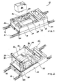
- Fig. 2
- eine Darstellung ähnlich der von
Fig. 1 mit einer auf zwei Tragprofil- schienen befestigten Haube für einen im Freien vorgesehenen Zähler- und Verteilerschrank, - Fig. 3
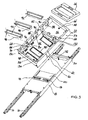
- eine perspektivisch auseinander gezogene Darstellung der Einzelteile der Halterung nach
Fig. 1 , - Fig. 4
- eine perspektivisch auseinander gezogene Darstellung der Einzelteile der Halterung nach
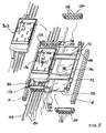
Fig. 2 , - Fig. 5
- eine perspektivisch auseinander gezogene Darstellung von Teilen einer anderen Ausführungsform einer Halterung für elektronische Haushalts- zähler eines im Freien vorgesehenen Zähler- und Verteilerschrankes,
- Fig. 6
- eine Darstellung ähnlich der von
Fig. 5 einer derartigen Halterung für elektronische Haushaltszähler eines innerhäuslichen Zähler- und Vertei- lerschrankes, - Fig. 7
- eine Querverdrahtung zwischen einem Adapter-Feld und einem seitlich daneben vorhandenen Einspeisungs-Feld.
- Fig. 1
- a perspective exploded view of a mounted on support rails holder for electronic household meter of a domestic meter and distribution cabinet,
- Fig. 2
- a representation similar to that of
Fig. 1 with a cover mounted on two support rails for an outdoor meter and distribution cabinet, - Fig. 3
- a perspective exploded view of the individual parts of the holder
Fig. 1 . - Fig. 4
- a perspective exploded view of the individual parts of the holder
Fig. 2 . - Fig. 5
- a perspective exploded view of parts of another embodiment of a holder for electronic household meter of an outdoor provided counter and distribution cabinet,
- Fig. 6
- a representation similar to that of
Fig. 5 Such a holder for electronic household counters of a domestic counter and distributor cabinet, - Fig. 7
- a cross-wiring between an adapter field and a laterally existing feed-in field.
In
Auf der Zählertragplatte 18 ist eine Haube 22 angeschraubt. Die in
In der Abdeckhaube 24 sind im vorliegenden Fall zwei nebeneinander liegende Fenster 27, 28 vorhanden. In dem einen Fenster 27 ist ein Adapter 30 zu erkennen, auf dem ein elektrischer Haushaltszähler 32 aufgesteckt und damit elektrisch angeschlossen werden kann. Die elektrische Kabelführung in die Haube 22 hinein und aus derselben heraus ist nicht dargestellt.In the cover 24, two
Unterhalb der Schutzabdeckung 26 ist ein Steuergeräteplatz ausgebildet, in dem Sicherungen oder sonstige elektronische Bauteile in an sich bekannter Art und Weise platziert werden können. Der Steuergeräteplatz könnte statt oberhalb auch unterhalb des die Zähler 32 aufnehmenden Feldes angeordnet sein. Sowohl die Abdeckhaube 24 als auch die Schutzabdeckung 26 sind in an sich bekannter Weise über Plombiermaßnahmen fest an der Haube 22 angebracht, so dass die Abdeckhaube 24 und die Schutzabdeckung 26 nicht zerstörungsfrei und damit nicht unbemerkt von der Haube 22 abgenommen werden können.Below the
Die gleiche Haube 22 ist auch bei der in
Die haubenartige Klarsichtabdeckung 34 ist in ihren vier Eckbereichen über Plombierschrauben 36, von denen jeweils zwei Plombierschrauben 36 über einen Haltebügel 38 beziehungsweise 40 verbunden sind, durch die Haube 22 hindurch an den beiden Tragprofilschienen 14,16 befestigt. Auch in diesem Falle wird über die Plombierschrauben 36 ein zerstörungsfreies Entfernen der Klarsichtabdeckung 34 verhindert. Entsprechendes gilt auch für die in
In
In der Bodenplatte 50 ist oben ein mittiger lochartiger Ausbrechbereich 66 und im - bezogen auf die
Auf der Innenseite der linken und rechten Seitenwand 52, 54 sind mehrere Anschraubtuben 80, 82, 84 vorhanden. Die Anschraubtuben ragen von der Innenseite der Bodenplatte 50 aus. Die obere Stirnseite 86 einer jeden Anschraubtube endet auf dem Niveau des Bodens 88 einer in der betreffenden Seitenwand 52 beziehungsweise 54 vorhandenen Nische 90. Auf jeweils zwei einander gegenüberliegenden solchen Anschraubtuben kann eine Hutschiene 92 aufgeschraubt werden. Im vorliegenden Fall ist die jeweilige Hutschiene 92 nicht unmittelbar, sondern mittelbar über ein Distanzstück 94 an den Anschraubtuben 80,82,84 angeschraubt. Die Höhe des Distanzstückes 94 richtet sich nach den geometrischen Anforderungen und den Höhenmaßen, die für die Abdeckhaube 24 und die Schutzabdeckung 26 an dem jeweiligen Schrank zur Verfügung stehen. Es wäre auch möglich, die Hutschienen 92 unmittelbar auf die Anschraubtuben 80, 82 beziehungsweise 84 aufzuschrauben, wie es bezüglich der beiden Anschraubtuben 84 im vorliegenden Beispielsfall dargestellt ist.On the inside of the left and
Auf den Hutschienen 92 können dann beispielsweise einer oder zwei Adapter 30 befestigt werden. Auf den einzelnen Adaptern 30 wird dann der jeweilige elektrische Haushaltszähler 32 aufgesteckt und die Abdeckplatte 24 auf die Haube aufgeschraubt. Die Abdeckhaube 24 und der elektrische Haushaltszähler können zerstörungsfrei nicht von der Befestigungskonstruktion entnommen werden.For example, one or two
In der Bodenplatte 50 der Haube 22 sind mehrere rechteckförmige Ausbrechbereiche vorgesehen, wie im vorliegenden Fall drei solcher Ausbrechbereiche 98, durch die jeweils elektrische Leitungen in das Innere der Haube hineingeführt beziehungsweise aus dem Inneren wieder herausgeführt werden können, was im einzelnen nicht dargestellt ist. Auch in der Zählertragplatte 18 ist eine mit einem Ausbrechbereich 98 korrespondierende Aussparung 100 vorhanden, um die Leitungen unter beziehungsweise hinter der Zählertragplatte 18 zwischen den beiden Tragprofilschienen 14,16 nach - bezogen auf die
Die bei einem im Freien aufgestellten Zähler- und Verteilerschrank vorhandene Haube 22 ist, wie
In der Haube 22 sind im Anschlussbereich zwischen der Bodenplatte 50 und der linken und rechten Seitenwand 52, 54 jeweils ein Längskanal 102,104 vorhanden, der jeweils durch die betreffende Seitenwand 52, 54 voll hindurchgeht und von denen in
In der linken und rechten Seitenwand 52, 54 sind jeweils drei Durchbohrungen 110, 112,114 vorhanden, die von vorne nach hinten beziehungsweise, bezogen auf die
An den Anschraubtuben 80, 82, 84 können wiederum Hutschienen 92 angeschraubt werden, die im Bereich der Böden 88 der in der linken und rechten Seitenwand 52, 54 vorhandenen Nischen 90 jeweils enden. Die Nischenböden 88 dienen zur kippsicheren Halterung der Hutschienen. Die gleiche kippsichere Halterung ist auch bei dem innerhäuslichen Zählerplatz (
Neben den Durchbohrungen 110,112,114 ist jeweils eine weitere Durchbohrung 116,118,120 in den beiden Seitenwänden 52, 54 vorhanden. Die Durchbohrungen 116,118 dienen zum Befestigen der Plombierschrauben 36. Die Durchbohrung 120 und eine weitere Durchbohrung 122 dient zum Befestigen der Schutzabdeckung 26.In addition to the
Zwecks Abdichtung der im Inneren der Haube 22 und der Klarsichtabdeckung 34 vorhandenen elektrischen und elektronischen Bauteile, wie beispielsweise dem elektrischen Haushaltszähler 32, kann der jeweils in der Bodenplatte 50 der Haube 22 zum Durchführen von Leitungen benötigte Ausbrechbereich 98 durch eine Abdichtplatte 124 verschlossen werden. In der Abdichtplatte 124, die aus witterungsbeständigem, flexiblem Kunststoff besteht, sind von elektrischen Leitungen durchstoßbare Kreisflächen vorhanden, die in an sich bekannter Weise es ermöglichen, die jeweilige Leitung spritzwasserdicht und staubdicht durch die Abdichtplatte 124 hindurchzuführen. Auf der umlaufenden Stirnseite 62 der linken und rechten Seitenwand 52, 54 und der vorderen Seitenwand 56 sowie der Querwand 64 läuft ein Dichtungsband 126 herum, das spritzwasserdicht und staubdicht auf der Haube 22 aufsitzt. Dieses in
Neben der unteren Seitenwand 56 und der Querwand 64 sind jeweils zwei Anschraubtuben 130 beziehungsweise 132 auskragend von der Bodenplatte 50 vorhanden. An diesen Anschraubtuben 130,132 lässt sich eine die Plätze für zwei Adapter 30 freilassende Abdeckplatte 134 festschrauben. Damit diese Abdeckplatte 134 niveaumäßig mit den Seitenwänden 54, 54, und den Querwänden 56, 64 abschließt, liegen die Stirnseiten der Anschraubtuben niveaumäßig etwas unterhalb der vorderen (oberen) Stirnseite 62 dieser Seitenwände.In addition to the
Während bei der vorstehend beschriebenen Halterung für elektronische Haushaltszähler 32, die im vorliegenden Beispielsfall aus einem jeweils zwei elektronische Haushaltszähler 32 und ihre beiden Adapter 30 aufnehmenden Gehäuse aus einer wannenartigen Haube 22 und einer dieselben abdeckenden Abdeckplatte 134 besteht, besteht in den nachstehend beschriebenen Halterungen gemäß
Das Unterteil, das anstatt der Haube 22 vorhanden ist, besitzt eine Bodenplatte 140, die seitlich zwei rippenartige Seitenwände 142,144 aufweist. Das untere und obere Ende der Bodenplatte 140 wird jeweils durch einen mittigen Wandbereich 146,148 und seitlich sich daran jeweils anschließende rippenartige Querwände 150,152 gebildet.The lower part, which is present instead of the
Auf den rippenförmigen Querwänden 150,152, und das betrifft sowohl den unteren als auch den oberen Bereich der Bodenplatte 140, können Steckschieber 154 jeweils aufgeschoben werden. Jeder Steckschieber 154 verrastet seitlich in entsprechend ausgebildeten Endbereichen der rippenartigen Seitenwände 142,144, beziehungsweise des jeweiligen mittigen Wandbereiches 146,148. In
Diese Kanalstücke 172 ermöglichen das problemlose auch nachträgliche Verdrahten des Adapters 30.2 und damit der optischen Schnittstelle 170 mit der Datenleitung 164. So kann die Datenleitung zielgesichert von außen durch die Steckschieber hindurch und in den Adapter 30.2 hineingeführt werden.These
In dem unteren und oberen mittleren Wandbereich 146, 148 ist die untere und obere Kanalöffnung 156 eines Mittelkanals 160 vorhanden. Der Mittelkanal 160 erstreckt sich auf der Bodenplatte 140 mit gleichem parallelen Abstand zu den beiden Tragprofilschienen 14,16. Durch den Mittelkanal 160 können dadurch Leitungen wie beispielsweise ein Null-Leiter längs durch den Bereich der Bodenplatte 140 von unten nach oben und umgekehrt hindurchgeführt werden.In the lower and upper
Oberhalb der Bodenplatte 140 sind zwei Hutschienen 92 vorhanden, auf der im vorliegenden Beispielsfall zwei Adapter 30.2 montiert werden können. Einer der beiden Adapter 30.2 ist bereits auf den beiden Hutschienen 92 befestigt.Above the
Durch den Adapter 30.2 sind, in vergleichbarer Weise wie bei dem Adapter 30, Leitungen hindurchgeführt. Diese Leitungen haben über den Adapter 30.2 elektrischen Kontakt mit dem einen oder den beiden elektrischen Haushaltszählem (eHZ) 32, so wie das an sich bekannt ist.By the adapter 30.2 are, in a similar manner as in the
Im vorliegenden Beispielsfall führt noch eine Datenleitung 164 von unten nach oben durch den Adapter 30.2 hindurch, die eine Verbindung mit einer auf der Oberseite des Adapters ausgebildeten optischen Schnittstelle 170 hat. Der Adapter 30.2 hat eine mit dieser optischen Schnittstelle 170 korrespondierende Schnittstelle.In the present example case, a
Auf der unteren und oberen Seite des Adapters 30.2 ragt ein rüsselartiges Kanalstück 172 jeweils nach unten beziehungsweise oben heraus. Durch die beiden rüsselartigen Kanalstücke 172 ist die Datenleitung 164 hindurchgeführt. Die beiden rüsselartigen Kanalstücke 172 enden jeweils an der dem Adapter 30.2 zugewandten Seite des jeweiligen Steckschiebers 154.On the lower and upper sides of the adapter 30.2, a trunk-
In dem Steckschieber 154 sind im vorliegenden Beispielsfall tulpenförmige oder konusförmige Dichtmembrane 176 ausgebildet. Diese Dichtmembrane 176 werden beim Durchführen sowohl der Datenleitung oder der sonstigen durch den Adapter 30.2 hindurchgeführten elektrischen Leitungen 180 durchstoßen. Die Dichtmembrane 176 verhindern, dass Schwitz- beziehungsweise Kondenswasser in das Innere des Gehäuses eindringen kann, das, wie bereits ausgeführt, auf der Rückseite des Zählerplatzes von der Bodenplatte 140 und von vorne durch eine Haube 182 (
Das Vorhandensein der Steckschieber 154 macht es möglich den Adapter 30.2 zusammen mit den durch ihn und durch den oberen und unteren Steckverbinder 154 hindurchgeführten Leitungen 180 und gegebenenfalls 164 als Einheit - auch nachträglich - auf den Hutschienen 92 zu montieren.The presence of the plug-in
Bei der Darstellung gemäß
Die nicht erforderlichen Ausbrechbereiche 98 bräuchten bei Zählerplätzen für im Freien aufzustellende Zählerschränke nicht vorgesehen zu werden. Die bei einer Benutzung der Ausbrechbereiche 98 erforderlichen Membran-Dichtplatten bräuchten dann herstellerseitig nicht zur Verfügung gestellt werden.The not required
Das einen oder die beiden Adapter 30.2 aufnehmende Gehäuse wird von vorne am Schrank durch das als Haube 182 gebildete Oberteil des entsprechenden Gehäuses verschlossen. In der Haube 182 sind entsprechend den beiden platzierbaren Adaptern 30.2 entsprechende zwei Fenster 27, 28 ausgespart, wie das auch bei der Ausführung gemäß
Die Leitungsführung durch einen Adapter hindurch kann grundsätzlich von - bezogen beispielsweise auf die
Claims (15)
Priority Applications (1)
| Application Number | Priority Date | Filing Date | Title |
|---|---|---|---|
| PL10003024T PL2234227T3 (en) | 2009-03-23 | 2010-03-23 | Holder for electronic household meters |
Applications Claiming Priority (1)
| Application Number | Priority Date | Filing Date | Title |
|---|---|---|---|
| DE202009003921U DE202009003921U1 (en) | 2009-03-23 | 2009-03-23 | Holder for electronic household meters |
Publications (3)
| Publication Number | Publication Date |
|---|---|
| EP2234227A2 true EP2234227A2 (en) | 2010-09-29 |
| EP2234227A3 EP2234227A3 (en) | 2013-02-27 |
| EP2234227B1 EP2234227B1 (en) | 2016-10-12 |
Family
ID=40691294
Family Applications (1)
| Application Number | Title | Priority Date | Filing Date |
|---|---|---|---|
| EP10003024.6A Active EP2234227B1 (en) | 2009-03-23 | 2010-03-23 | Holder for electronic household meters |
Country Status (3)
| Country | Link |
|---|---|
| EP (1) | EP2234227B1 (en) |
| DE (1) | DE202009003921U1 (en) |
| PL (1) | PL2234227T3 (en) |
Cited By (2)
| Publication number | Priority date | Publication date | Assignee | Title |
|---|---|---|---|---|
| CN111650410A (en) * | 2020-06-12 | 2020-09-11 | 王乐炯 | Transparent ammeter case of glass steel matter |
| CN113594913A (en) * | 2021-09-09 | 2021-11-02 | 新昌县银邦电力科技有限公司 | Power distribution cabinet instrument for chemical workshop and power distribution cabinet |
Families Citing this family (3)
| Publication number | Priority date | Publication date | Assignee | Title |
|---|---|---|---|---|
| DE102009030255A1 (en) * | 2009-06-23 | 2010-12-30 | Hager Electro Gmbh & Co. Kg | adapter assembly |
| BE1022597B1 (en) * | 2013-12-20 | 2016-06-14 | Teconex | Electric box |
| CN112366535B (en) * | 2020-09-18 | 2022-07-26 | 安徽正日电气有限公司 | Low-voltage electric energy metering device |
Citations (1)
| Publication number | Priority date | Publication date | Assignee | Title |
|---|---|---|---|---|
| DE102006050701A1 (en) | 2005-11-09 | 2007-05-10 | Abn Werner Braun Gmbh | Meter and distribution cabinet for electrical installation, has load carrying system which is designed like trough partially open at its upper and lower ends, where trough consists of non-electro conductive material such as plastic |
Family Cites Families (2)
| Publication number | Priority date | Publication date | Assignee | Title |
|---|---|---|---|---|
| DE102004022784A1 (en) * | 2004-05-08 | 2005-12-01 | Abb Patent Gmbh | In a meter cabinet mountable meter slot module |
| DE102005063203A1 (en) * | 2005-12-31 | 2007-07-05 | Abb Patent Gmbh | distribution device |
-
2009
- 2009-03-23 DE DE202009003921U patent/DE202009003921U1/en not_active Expired - Lifetime
-
2010
- 2010-03-23 PL PL10003024T patent/PL2234227T3/en unknown
- 2010-03-23 EP EP10003024.6A patent/EP2234227B1/en active Active
Patent Citations (1)
| Publication number | Priority date | Publication date | Assignee | Title |
|---|---|---|---|---|
| DE102006050701A1 (en) | 2005-11-09 | 2007-05-10 | Abn Werner Braun Gmbh | Meter and distribution cabinet for electrical installation, has load carrying system which is designed like trough partially open at its upper and lower ends, where trough consists of non-electro conductive material such as plastic |
Cited By (2)
| Publication number | Priority date | Publication date | Assignee | Title |
|---|---|---|---|---|
| CN111650410A (en) * | 2020-06-12 | 2020-09-11 | 王乐炯 | Transparent ammeter case of glass steel matter |
| CN113594913A (en) * | 2021-09-09 | 2021-11-02 | 新昌县银邦电力科技有限公司 | Power distribution cabinet instrument for chemical workshop and power distribution cabinet |
Also Published As
| Publication number | Publication date |
|---|---|
| EP2234227B1 (en) | 2016-10-12 |
| DE202009003921U1 (en) | 2009-05-28 |
| PL2234227T3 (en) | 2017-07-31 |
| EP2234227A3 (en) | 2013-02-27 |
Similar Documents
| Publication | Publication Date | Title |
|---|---|---|
| EP1593978B1 (en) | Subassembly of a mounting for meters mountable in a cabinet | |
| EP2234227B1 (en) | Holder for electronic household meters | |
| DE102006002478A1 (en) | Base plate and cable distribution cabinet with base plate | |
| DE202009003651U1 (en) | Frame for a test cell | |
| EP1992953A2 (en) | Meter connection pad with a meter base plate for accepting at least two electricity meters | |
| DE202016100561U1 (en) | Device for power and / or signal transmission to be arranged on a shelf, in particular a sales shelf customers | |
| DE1949694C3 (en) | Low-voltage distributor arranged underground | |
| EP0837535A2 (en) | Distribution duct for intensive care | |
| DE102012110247A1 (en) | Switch cabinet with improved possibility for stringing together | |
| DE202007016555U1 (en) | Control cabinet, in particular built-in wardrobe in 19-inch design | |
| EP2267462B1 (en) | Adapter component | |
| DE102005013403B4 (en) | In a meter cabinet einbaubares meter field for at least one electricity meter | |
| DE102004022782B4 (en) | meter cabinet | |
| EP0062937B1 (en) | Electrical switchgear cabinet | |
| DE102004054173B4 (en) | Low voltage switch cabinet | |
| DE19817386C2 (en) | switch cabinet | |
| DE10210754B4 (en) | Control cabinet with a frame and a cable entry in the top wall | |
| DE19947732C2 (en) | Wall-mountable bracket that can be used as a cable distributor | |
| CH713832A2 (en) | Fastening device, door for a control cabinet and a control cabinet comprising such a door. | |
| DE19713948A1 (en) | Inner construction system for switching cabinets | |
| EP0677906A1 (en) | Flush mounted box for at least one electrical apparatus | |
| DE102010047179B4 (en) | Meter and distribution cabinet | |
| DE102006056962B4 (en) | Arrangement of a housing with telecommunications installations and an energy connection column | |
| DE19953187A1 (en) | Electrical installation part for connecting data lines | |
| DE1690170C3 (en) | Combined connection device for different types of supply systems |
Legal Events
| Date | Code | Title | Description |
|---|---|---|---|
| PUAI | Public reference made under article 153(3) epc to a published international application that has entered the european phase |
Free format text: ORIGINAL CODE: 0009012 |
|
| AK | Designated contracting states |
Kind code of ref document: A2 Designated state(s): AT BE BG CH CY CZ DE DK EE ES FI FR GB GR HR HU IE IS IT LI LT LU LV MC MK MT NL NO PL PT RO SE SI SK SM TR |
|
| AX | Request for extension of the european patent |
Extension state: AL BA ME RS |
|
| TPAC | Observations filed by third parties |
Free format text: ORIGINAL CODE: EPIDOSNTIPA |
|
| PUAL | Search report despatched |
Free format text: ORIGINAL CODE: 0009013 |
|
| AK | Designated contracting states |
Kind code of ref document: A3 Designated state(s): AT BE BG CH CY CZ DE DK EE ES FI FR GB GR HR HU IE IS IT LI LT LU LV MC MK MT NL NO PL PT RO SE SI SK SM TR |
|
| AX | Request for extension of the european patent |
Extension state: AL BA ME RS |
|
| RIC1 | Information provided on ipc code assigned before grant |
Ipc: H02B 1/03 20060101AFI20130122BHEP |
|
| 17P | Request for examination filed |
Effective date: 20130819 |
|
| RBV | Designated contracting states (corrected) |
Designated state(s): AT BE BG CH CY CZ DE DK EE ES FI FR GB GR HR HU IE IS IT LI LT LU LV MC MK MT NL NO PL PT RO SE SI SK SM TR |
|
| GRAP | Despatch of communication of intention to grant a patent |
Free format text: ORIGINAL CODE: EPIDOSNIGR1 |
|
| INTG | Intention to grant announced |
Effective date: 20160504 |
|
| RAP1 | Party data changed (applicant data changed or rights of an application transferred) |
Owner name: HAGER ELECTRO GMBH & CO. KG |
|
| GRAS | Grant fee paid |
Free format text: ORIGINAL CODE: EPIDOSNIGR3 |
|
| GRAA | (expected) grant |
Free format text: ORIGINAL CODE: 0009210 |
|
| AK | Designated contracting states |
Kind code of ref document: B1 Designated state(s): AT BE BG CH CY CZ DE DK EE ES FI FR GB GR HR HU IE IS IT LI LT LU LV MC MK MT NL NO PL PT RO SE SI SK SM TR |
|
| REG | Reference to a national code |
Ref country code: GB Ref legal event code: FG4D Free format text: NOT ENGLISH |
|
| REG | Reference to a national code |
Ref country code: CH Ref legal event code: EP |
|
| REG | Reference to a national code |
Ref country code: AT Ref legal event code: REF Ref document number: 837269 Country of ref document: AT Kind code of ref document: T Effective date: 20161015 |
|
| REG | Reference to a national code |
Ref country code: IE Ref legal event code: FG4D Free format text: LANGUAGE OF EP DOCUMENT: GERMAN |
|
| REG | Reference to a national code |
Ref country code: DE Ref legal event code: R096 Ref document number: 502010012527 Country of ref document: DE |
|
| REG | Reference to a national code |
Ref country code: CH Ref legal event code: NV Representative=s name: ALDO ROEMPLER PATENTANWALT, CH |
|
| REG | Reference to a national code |
Ref country code: LT Ref legal event code: MG4D |
|
| REG | Reference to a national code |
Ref country code: NL Ref legal event code: MP Effective date: 20161012 |
|
| PG25 | Lapsed in a contracting state [announced via postgrant information from national office to epo] |
Ref country code: LV Free format text: LAPSE BECAUSE OF FAILURE TO SUBMIT A TRANSLATION OF THE DESCRIPTION OR TO PAY THE FEE WITHIN THE PRESCRIBED TIME-LIMIT Effective date: 20161012 |
|
| REG | Reference to a national code |
Ref country code: FR Ref legal event code: PLFP Year of fee payment: 8 |
|
| PG25 | Lapsed in a contracting state [announced via postgrant information from national office to epo] |
Ref country code: GR Free format text: LAPSE BECAUSE OF FAILURE TO SUBMIT A TRANSLATION OF THE DESCRIPTION OR TO PAY THE FEE WITHIN THE PRESCRIBED TIME-LIMIT Effective date: 20170113 Ref country code: SE Free format text: LAPSE BECAUSE OF FAILURE TO SUBMIT A TRANSLATION OF THE DESCRIPTION OR TO PAY THE FEE WITHIN THE PRESCRIBED TIME-LIMIT Effective date: 20161012 Ref country code: NO Free format text: LAPSE BECAUSE OF FAILURE TO SUBMIT A TRANSLATION OF THE DESCRIPTION OR TO PAY THE FEE WITHIN THE PRESCRIBED TIME-LIMIT Effective date: 20170112 Ref country code: LT Free format text: LAPSE BECAUSE OF FAILURE TO SUBMIT A TRANSLATION OF THE DESCRIPTION OR TO PAY THE FEE WITHIN THE PRESCRIBED TIME-LIMIT Effective date: 20161012 |
|
| PG25 | Lapsed in a contracting state [announced via postgrant information from national office to epo] |
Ref country code: IS Free format text: LAPSE BECAUSE OF FAILURE TO SUBMIT A TRANSLATION OF THE DESCRIPTION OR TO PAY THE FEE WITHIN THE PRESCRIBED TIME-LIMIT Effective date: 20170212 Ref country code: PT Free format text: LAPSE BECAUSE OF FAILURE TO SUBMIT A TRANSLATION OF THE DESCRIPTION OR TO PAY THE FEE WITHIN THE PRESCRIBED TIME-LIMIT Effective date: 20170213 Ref country code: ES Free format text: LAPSE BECAUSE OF FAILURE TO SUBMIT A TRANSLATION OF THE DESCRIPTION OR TO PAY THE FEE WITHIN THE PRESCRIBED TIME-LIMIT Effective date: 20161012 Ref country code: FI Free format text: LAPSE BECAUSE OF FAILURE TO SUBMIT A TRANSLATION OF THE DESCRIPTION OR TO PAY THE FEE WITHIN THE PRESCRIBED TIME-LIMIT Effective date: 20161012 Ref country code: HR Free format text: LAPSE BECAUSE OF FAILURE TO SUBMIT A TRANSLATION OF THE DESCRIPTION OR TO PAY THE FEE WITHIN THE PRESCRIBED TIME-LIMIT Effective date: 20161012 Ref country code: NL Free format text: LAPSE BECAUSE OF FAILURE TO SUBMIT A TRANSLATION OF THE DESCRIPTION OR TO PAY THE FEE WITHIN THE PRESCRIBED TIME-LIMIT Effective date: 20161012 |
|
| REG | Reference to a national code |
Ref country code: DE Ref legal event code: R097 Ref document number: 502010012527 Country of ref document: DE |
|
| PG25 | Lapsed in a contracting state [announced via postgrant information from national office to epo] |
Ref country code: SK Free format text: LAPSE BECAUSE OF FAILURE TO SUBMIT A TRANSLATION OF THE DESCRIPTION OR TO PAY THE FEE WITHIN THE PRESCRIBED TIME-LIMIT Effective date: 20161012 Ref country code: EE Free format text: LAPSE BECAUSE OF FAILURE TO SUBMIT A TRANSLATION OF THE DESCRIPTION OR TO PAY THE FEE WITHIN THE PRESCRIBED TIME-LIMIT Effective date: 20161012 Ref country code: DK Free format text: LAPSE BECAUSE OF FAILURE TO SUBMIT A TRANSLATION OF THE DESCRIPTION OR TO PAY THE FEE WITHIN THE PRESCRIBED TIME-LIMIT Effective date: 20161012 Ref country code: RO Free format text: LAPSE BECAUSE OF FAILURE TO SUBMIT A TRANSLATION OF THE DESCRIPTION OR TO PAY THE FEE WITHIN THE PRESCRIBED TIME-LIMIT Effective date: 20161012 Ref country code: CZ Free format text: LAPSE BECAUSE OF FAILURE TO SUBMIT A TRANSLATION OF THE DESCRIPTION OR TO PAY THE FEE WITHIN THE PRESCRIBED TIME-LIMIT Effective date: 20161012 |
|
| PLBE | No opposition filed within time limit |
Free format text: ORIGINAL CODE: 0009261 |
|
| STAA | Information on the status of an ep patent application or granted ep patent |
Free format text: STATUS: NO OPPOSITION FILED WITHIN TIME LIMIT |
|
| PG25 | Lapsed in a contracting state [announced via postgrant information from national office to epo] |
Ref country code: IT Free format text: LAPSE BECAUSE OF FAILURE TO SUBMIT A TRANSLATION OF THE DESCRIPTION OR TO PAY THE FEE WITHIN THE PRESCRIBED TIME-LIMIT Effective date: 20161012 Ref country code: SM Free format text: LAPSE BECAUSE OF FAILURE TO SUBMIT A TRANSLATION OF THE DESCRIPTION OR TO PAY THE FEE WITHIN THE PRESCRIBED TIME-LIMIT Effective date: 20161012 Ref country code: BG Free format text: LAPSE BECAUSE OF FAILURE TO SUBMIT A TRANSLATION OF THE DESCRIPTION OR TO PAY THE FEE WITHIN THE PRESCRIBED TIME-LIMIT Effective date: 20170112 |
|
| 26N | No opposition filed |
Effective date: 20170713 |
|
| GBPC | Gb: european patent ceased through non-payment of renewal fee |
Effective date: 20170323 |
|
| PG25 | Lapsed in a contracting state [announced via postgrant information from national office to epo] |
Ref country code: MC Free format text: LAPSE BECAUSE OF FAILURE TO SUBMIT A TRANSLATION OF THE DESCRIPTION OR TO PAY THE FEE WITHIN THE PRESCRIBED TIME-LIMIT Effective date: 20161012 Ref country code: SI Free format text: LAPSE BECAUSE OF FAILURE TO SUBMIT A TRANSLATION OF THE DESCRIPTION OR TO PAY THE FEE WITHIN THE PRESCRIBED TIME-LIMIT Effective date: 20161012 |
|
| REG | Reference to a national code |
Ref country code: IE Ref legal event code: MM4A |
|
| PG25 | Lapsed in a contracting state [announced via postgrant information from national office to epo] |
Ref country code: LU Free format text: LAPSE BECAUSE OF NON-PAYMENT OF DUE FEES Effective date: 20170323 |
|
| PG25 | Lapsed in a contracting state [announced via postgrant information from national office to epo] |
Ref country code: IE Free format text: LAPSE BECAUSE OF NON-PAYMENT OF DUE FEES Effective date: 20170323 Ref country code: GB Free format text: LAPSE BECAUSE OF NON-PAYMENT OF DUE FEES Effective date: 20170323 |
|
| REG | Reference to a national code |
Ref country code: BE Ref legal event code: MM Effective date: 20170331 |
|
| REG | Reference to a national code |
Ref country code: FR Ref legal event code: PLFP Year of fee payment: 9 |
|
| PG25 | Lapsed in a contracting state [announced via postgrant information from national office to epo] |
Ref country code: BE Free format text: LAPSE BECAUSE OF NON-PAYMENT OF DUE FEES Effective date: 20170331 |
|
| PG25 | Lapsed in a contracting state [announced via postgrant information from national office to epo] |
Ref country code: MT Free format text: LAPSE BECAUSE OF FAILURE TO SUBMIT A TRANSLATION OF THE DESCRIPTION OR TO PAY THE FEE WITHIN THE PRESCRIBED TIME-LIMIT Effective date: 20161012 |
|
| PG25 | Lapsed in a contracting state [announced via postgrant information from national office to epo] |
Ref country code: HU Free format text: LAPSE BECAUSE OF FAILURE TO SUBMIT A TRANSLATION OF THE DESCRIPTION OR TO PAY THE FEE WITHIN THE PRESCRIBED TIME-LIMIT; INVALID AB INITIO Effective date: 20100323 |
|
| PG25 | Lapsed in a contracting state [announced via postgrant information from national office to epo] |
Ref country code: CY Free format text: LAPSE BECAUSE OF NON-PAYMENT OF DUE FEES Effective date: 20161012 |
|
| PG25 | Lapsed in a contracting state [announced via postgrant information from national office to epo] |
Ref country code: MK Free format text: LAPSE BECAUSE OF FAILURE TO SUBMIT A TRANSLATION OF THE DESCRIPTION OR TO PAY THE FEE WITHIN THE PRESCRIBED TIME-LIMIT Effective date: 20161012 |
|
| PG25 | Lapsed in a contracting state [announced via postgrant information from national office to epo] |
Ref country code: TR Free format text: LAPSE BECAUSE OF FAILURE TO SUBMIT A TRANSLATION OF THE DESCRIPTION OR TO PAY THE FEE WITHIN THE PRESCRIBED TIME-LIMIT Effective date: 20161012 |
|
| PGFP | Annual fee paid to national office [announced via postgrant information from national office to epo] |
Ref country code: FR Payment date: 20230327 Year of fee payment: 14 Ref country code: AT Payment date: 20230303 Year of fee payment: 14 |
|
| PGFP | Annual fee paid to national office [announced via postgrant information from national office to epo] |
Ref country code: PL Payment date: 20230302 Year of fee payment: 14 |
|
| P01 | Opt-out of the competence of the unified patent court (upc) registered |
Effective date: 20230606 |
|
| PGFP | Annual fee paid to national office [announced via postgrant information from national office to epo] |
Ref country code: CH Payment date: 20230402 Year of fee payment: 14 |
|
| PGFP | Annual fee paid to national office [announced via postgrant information from national office to epo] |
Ref country code: AT Payment date: 20240304 Year of fee payment: 15 |
|
| PGFP | Annual fee paid to national office [announced via postgrant information from national office to epo] |
Ref country code: DE Payment date: 20240327 Year of fee payment: 15 |