EP2234081A2 - Method for producing a known fixed spatial relationship between a laser scanner and a digital camera for traffic monitoring - Google Patents
Method for producing a known fixed spatial relationship between a laser scanner and a digital camera for traffic monitoring Download PDFInfo
- Publication number
- EP2234081A2 EP2234081A2 EP10157441A EP10157441A EP2234081A2 EP 2234081 A2 EP2234081 A2 EP 2234081A2 EP 10157441 A EP10157441 A EP 10157441A EP 10157441 A EP10157441 A EP 10157441A EP 2234081 A2 EP2234081 A2 EP 2234081A2
- Authority
- EP
- European Patent Office
- Prior art keywords
- digital camera
- vehicle
- laser scanner
- coordinate system
- measured values
- Prior art date
- Legal status (The legal status is an assumption and is not a legal conclusion. Google has not performed a legal analysis and makes no representation as to the accuracy of the status listed.)
- Granted
Links
Images

Classifications
-
- G—PHYSICS
- G08—SIGNALLING
- G08G—TRAFFIC CONTROL SYSTEMS
- G08G1/00—Traffic control systems for road vehicles
- G08G1/01—Detecting movement of traffic to be counted or controlled
- G08G1/017—Detecting movement of traffic to be counted or controlled identifying vehicles
- G08G1/0175—Detecting movement of traffic to be counted or controlled identifying vehicles by photographing vehicles, e.g. when violating traffic rules
-
- G—PHYSICS
- G01—MEASURING; TESTING
- G01S—RADIO DIRECTION-FINDING; RADIO NAVIGATION; DETERMINING DISTANCE OR VELOCITY BY USE OF RADIO WAVES; LOCATING OR PRESENCE-DETECTING BY USE OF THE REFLECTION OR RERADIATION OF RADIO WAVES; ANALOGOUS ARRANGEMENTS USING OTHER WAVES
- G01S17/00—Systems using the reflection or reradiation of electromagnetic waves other than radio waves, e.g. lidar systems
- G01S17/86—Combinations of lidar systems with systems other than lidar, radar or sonar, e.g. with direction finders
-
- G—PHYSICS
- G01—MEASURING; TESTING
- G01S—RADIO DIRECTION-FINDING; RADIO NAVIGATION; DETERMINING DISTANCE OR VELOCITY BY USE OF RADIO WAVES; LOCATING OR PRESENCE-DETECTING BY USE OF THE REFLECTION OR RERADIATION OF RADIO WAVES; ANALOGOUS ARRANGEMENTS USING OTHER WAVES
- G01S17/00—Systems using the reflection or reradiation of electromagnetic waves other than radio waves, e.g. lidar systems
- G01S17/88—Lidar systems specially adapted for specific applications
- G01S17/89—Lidar systems specially adapted for specific applications for mapping or imaging
-
- G—PHYSICS
- G01—MEASURING; TESTING
- G01S—RADIO DIRECTION-FINDING; RADIO NAVIGATION; DETERMINING DISTANCE OR VELOCITY BY USE OF RADIO WAVES; LOCATING OR PRESENCE-DETECTING BY USE OF THE REFLECTION OR RERADIATION OF RADIO WAVES; ANALOGOUS ARRANGEMENTS USING OTHER WAVES
- G01S7/00—Details of systems according to groups G01S13/00, G01S15/00, G01S17/00
- G01S7/48—Details of systems according to groups G01S13/00, G01S15/00, G01S17/00 of systems according to group G01S17/00
- G01S7/497—Means for monitoring or calibrating
- G01S7/4972—Alignment of sensor
-
- G—PHYSICS
- G08—SIGNALLING
- G08G—TRAFFIC CONTROL SYSTEMS
- G08G1/00—Traffic control systems for road vehicles
- G08G1/01—Detecting movement of traffic to be counted or controlled
- G08G1/052—Detecting movement of traffic to be counted or controlled with provision for determining speed or overspeed
- G08G1/054—Detecting movement of traffic to be counted or controlled with provision for determining speed or overspeed photographing overspeeding vehicles
Definitions
- an area of a roadway is monitored for an event out and in the event of the occurrence of the event by means of a digital camera, a photographic recording is created.
- the event can, for. Example, be a vehicle that passes through the monitored area with an excessive speed compared to a predetermined limit speed.
- the event could also be a vehicle traveling on a lane not authorized for the type of vehicle concerned, or the surveillance area in an inadmissible time window, e.g. B. enters during the red phase of a traffic light.
- the DE 10 2009 007 055.9 relates to a method which solves the problem of unambiguous assignment, in particular the assignment of a measured speed of a vehicle to a vehicle imaged in an image document.
- a measuring beam is scanned horizontally across a roadway over a predetermined measuring angle range, so that vehicles generate measured values as they travel through the forming scanning plane, from which the speed of the vehicles and the temporal change of the position can be determined.
- the measuring beam is a pulsed laser beam which scans the horizontal scanning plane several times with a constant, predetermined scanning frequency and a constant, predetermined pulse frequency.
- a laser scanner is set up next to the road at an acute angle to the roadway direction.
- the laser beam strikes vehicles in the measuring angle range and is reflected.
- the respective impact point is in each case described by a measuring point P n .
- the transit time of the pulsed laser beam (pulse transit time) to the appropriate vehicle and back correlates with the distance covered, from which the distance e n of a measurement point P n derived from the roadside laser scanner and a time t n and a current scan angle ⁇ n can be assigned.
- the measurement points P n can be described with temporal assignment in a polar coordinate system (scanner coordinate system), which is determined by the location and orientation of the laser scanner.
- the speed of the appropriate vehicle After the speed of the appropriate vehicle has been determined from the measured values, it is compared with a predetermined limit speed and in case of exceeding a digital camera is triggered to take an electronic picture as soon as this vehicle is at a predetermined distance to the digital camera, the photo distance e photo , located.
- the electronic recording is saved so that a proof photo can be printed out at any time.
- the digital camera is connected via a control and evaluation unit with the laser scanner and is basically to the laser scanner and the road surface are aligned and set to be sharp images an object field with a width of the angular range in the photo-photo distance e.
- a mark is generated from the measured values.
- the measured values which are obtained within the time-closest scan at the time of the triggering of the digital camera are stored.
- the measured values of the scan are stored during which the photo removal e pragmatic was also determined.
- the measured values of a scan represent a multiplicity of measured value pairs, from a current scan angle ⁇ n and a distance e n , which respectively represent a measuring point P n .
- the vehicle surface more specifically the vehicle front and a vehicle side, as "seen" by the scanner, along a line in the scan plane causes a finite number of pairs of measurements describing an angle-forming path pair.
- All measured value pairs which together describe an angle-forming pair of tracks (referred to below as object angles), form a group, which are each generated by a vehicle. It is clear to the person skilled in the art that the measuring points P n determined by the measured value pairs are practically only approximately on a straight line, and the object angle is laid in the group of measured value pairs by mathematical approximation methods. According to the DE 10 2009 007 055.9 a marker is to be generated from the group of measured value pairs, which is superimposed with the photographic image, so that an image is formed in which on the appropriate vehicle a marking along the measuring points across the width and / or length of the imaged vehicle preferably at the level of Scan plane is created.
- the group of measured value pairs which represent measuring points P n on the vehicle in the horizontal scanning plane, is transformed into a group of pixels which represent correlating points in the image of the perspective-recorded vehicle, that is to say in the picture. From the group of pixels, a digitized mark is now formed that includes the pixels.
- the electronically recorded image data of the vehicle acquired with the recording can be stored as a digitized recording in a file together with the digitized marking so that, when the file is visualized, the marking visibly superimposes the appropriate vehicle.
- the files are superimposed, so that here too the appropriate vehicle is superimposed by the marking.
- the digitized image of the vehicle, especially the license plate remains unaffected and preserved with their full information.
- the marker then overlays only temporarily for viewing the recording on a screen or for printing a photo of the recording of the vehicle.
- the group of measured value pairs By transforming the group of measured value pairs into a group of pixels, it is possible to generate a marking which, when superimposed on the image of the vehicle, exactly covers the measuring points P n which are instantaneous when the digital camera was triggered. That is, the mark is formed on the imaged vehicle along the impact points.
- the marking covers all these measuring points P n and extends as a line completely over the length and width of the visible sides of the imaged vehicle.
- the certainty that the marked vehicle is also the appropriate vehicle is given by the fact that the measurement data used to mark the vehicle at the moment of creating an electronic recording of the appropriate vehicle by the vehicle itself are effected.
- a laser scanner and a digital camera which should work together in a device coordinated with each other, while the assembly of the device is still adjusted to each other at the manufacturer.
- the axis of the laser scanner, around which the laser beam is deflected by a constantly changing scan angle, and the optical axis of the digital camera are adjusted to each other so that they "see” the measuring body from a same angle with the help of a stationary measuring body.
- the axes are therefore aligned parallel to each other with as small as possible, to the measurement distance, which is determined by the photo point, negligible axial distance.
- the measured values of the individual measuring points can then be converted into a Cartesian coordinate system and transformed into the associated pixels using the imaging characteristic of the digital camera, in particular the focal length of the camera objective.
- the disadvantage is that as a result of the adjustment of the laser scanner and the digital camera must be stabilized to each other.
- an adjustment is not possible in advance.
- the scanner can scan the surveillance area also vertically or at an angle of inclination between 0 ° and 90 ° to z. B. to capture the vehicle profile.
- the co-axial alignment of the laser scanner axis and camera axis is not always meaningful.
- the digital camera is to be aligned at a height above the roadway and to the direction of travel in such a way that the driver is depicted frontally.
- a laser scanner with a laser scanner axis, around which the laser beam is deflected by a constantly changing scan angle, and a digital camera with an optical axis around which the digital camera and thus its image plane can be arbitrarily rotated, are aligned with one another, the surveillance area, determined by the scan angle area, is completely covered by the object field of the digital camera at a predetermined photo point.
- the laser scanner is advantageously placed next to the roadway to scan the surveillance area in a horizontal plane or mounted above the roadway to scan a vertical plane.
- other arrangements of the laser scanner are possible, for.
- the difference is that, in the case of horizontal scanning, the position of the vehicle is basically completely detected with a scan, while vertical scanning as a function of the vehicle speed requires a large number of scans in order to capture the vehicle completely in its volume model ,
- the measured values formed by measuring points in only one plane ideally represent a line in the form of an angle, which changes its leg position when the vehicle is detected by several scans.
- the angle is a recognizable on the vehicle measurement structure.
- the readings When scanning from a significantly elevated scanner position, the readings describe an area that corresponds to a projection onto the vehicle.
- the perimeter of this area ideally represents a rectangle in the vertical scan direction, which represents a measurement structure recognizable on the vehicle.
- the laser scanner axis is directed obliquely onto the road surface, a side surface and the top surface and even the front surface are detected if the vertical plane is not perpendicular to the vertical plane Lane direction runs.
- the circumferential lines of the surfaces described by the measured values again represent a recognizable measuring structure.
- Such measuring structures can also be obtained from the measured values of a plurality of laser scanners, the z. B. detect a vehicle on the one hand in a horizontal and the other in a vertical scan plane.
- a vehicle passing through the surveillance area is scanned.
- the laser beam is reflected by the vehicle in its points of impact (hereinafter referred to as measuring points), with which measured values are generated.
- measuring points points of impact
- the measured values are generated per scan as a function of the pulse rate and the scan speed. They are formed by a plurality of measured value pairs from a distance e n and an angle value ⁇ n and in each case describe the location of a measuring point P n (e n ; ⁇ n ) within a scanner coordinate system 1. From these measurements, those are filtered out computationally, which together form a recognizable on the vehicle measurement structure.
- a vehicle passing through the surveillance area is scanned in a horizontal plane, so that approximately an angle is created as the measurement structure.
- the angle is formed by a line along the front of the vehicle and the side of the vehicle "seen" by the laser scanner at the level of the scan plane.
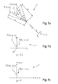
- Fig. 1a is the scanner coordinate system 1, a polar coordinate system, in the example, five measuring points are shown, shown.
- the measured values of the measuring points P n of the measuring structure described by polar coordinates are converted into Cartesian coordinates of a Cartesian coordinate system likewise assigned to the laser scanner (hereinafter referred to as coordinate system 2), the resulting values for the z-axis coinciding with the laser scanner axis coincides, be set to zero.
- the measured values are now displayed in one plane, see Fig. 1 b.
- the transformed coordinate system 2 has the same coordinate origin as the scanner coordinate system 1.
- the amounts for the translational movement are at least roughly specified. They are either known because the laser scanner and the digital camera are in a common housing or they are obtained by measuring the distances of the laser scanner to the digital camera along the coordinate axes of the transformed digital camera.
- the translational position can also be obtained by mathematical compensation method by automatically matched scan images with the associated camera images algorithmically.
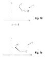
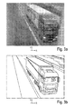
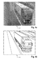
- the measurement values of the measurement structure By translating the measurement values of the measurement structure in a computational manner, they are placed in the camera coordinate system 3 ( Fig. 1c ). Since the measured values related to the transformed coordinate system 2 are only translationally transformed into the camera coordinate system 3 and this only roughly, the measuring structure does not superimpose the image of the vehicle along the measurement points on the vehicle determining the measuring structure (FIG. Fig. 2a and 2b ). In order to exactly overlay the measurement structure with the measurement points on the vehicle, a small translational displacement in the direction of the X axis and a rotational movement about the Y axis is required in order to arrive at an intermediate stage, as in FIG Fig. 3a and 3b shown, as well as a rotational movement about the X-axis and low translational displacement in the direction of the Y-axis, to the final stage, as in Fig. 4a and 4b shown to arrive.
- z. B transport-induced change in the relative position between the laser scanner and the digital camera. Like the rotary movements, they are not performed by changing the relative position between the laser scanner and the digital camera, but only computationally.
- the rotation angles can be determined such that a user changes the rotation angles in an iterative process in such a way that the image of the determined legs, ie the measurement structure, is superimposed in the correct position on the vehicle image ( Fig. 4a ).
- both the translational displacements and the rotational movements preferably take place interactively.
- This is a Input device, z. As joystick, mouse, keyboard o. ⁇ ., And an output device such.
- a screen or a combined input and output device eg. As a device with touch screen, at least temporarily connected to the traffic monitoring device.
- a measurement structure is determined from the appropriate measured values and superimposed on the photo of the digital camera and displayed on the output device as a marker.
- the marker is moved and / or rotated over the input device until it ideally superimposes the vehicle. This process is preferably repeated until the marking exactly overlaps the imaged vehicle without further correction.
- the proposed method is used for a subsequent traffic monitoring on the one hand to ensure that the vehicle detected by the laser scanner is also the vehicle depicted and on the other hand can be identified by the identification of the measurement structure by means of a marker that is inserted into the electronic image of the vehicle, the detected vehicle be marked.
- the latter is particularly advantageous if the traffic monitoring comprises several lanes of a roadway.
- the method according to the invention is particularly advantageous in that, apart from the initial coarse alignment between laser scanner and digital camera, the production of a known spatial relationship between a scanner coordinate system 1 determined by the laser scanner and a camera coordinate system 3 determined by the digital camera does not result from a relative change in position between the laser scanner and the camera Digital camera takes place, but only computationally, so that the preparations for traffic monitoring on site can be done faster and, above all, safe.
- the proposed method of alignment between a coordinate system of a measuring device and a camera coordinate system 3 can be used mutatis mutandis for any type of measurement systems in which the meter provides a position indication of the vehicle.
Abstract
Description
Verfahren zur Herstellung einer bekannten festen räumlichen Beziehung zwischen einem Laserscanner und einer Digitalkamera zur VerkehrsüberwachungA method of producing a known fixed spatial relationship between a laser scanner and a digital camera for traffic surveillance
Insbesondere aus der Verkehrsmesstechnik sind Verfahren und Vorrichtungen bekannt, mit denen mittels eines Laserscanners ein Bereich einer Fahrbahn auf ein Ereignis hin überwacht wird und im Falle des Eintretens des Ereignisses mittels einer Digitalkamera eine fotografische Aufnahme erstellt wird.
Das Ereignis kann z. B. ein Fahrzeug sein, das mit einer überhöhten Geschwindigkeit im Vergleich zu einer vorgegebenen Grenzgeschwindigkeit den Überwachungsbereich durchfährt. Das Ereignis könnte auch ein Fahrzeug sein, das auf einer für den betreffenden Fahrzeugtyp nicht zugelassenen Spur fährt, oder in den Überwachungsbereich in einem unzulässigen Zeitfenster, z. B. während der Rotphase einer Verkehrsampel einfährt.In particular, from traffic engineering methods and devices are known with which by means of a laser scanner, an area of a roadway is monitored for an event out and in the event of the occurrence of the event by means of a digital camera, a photographic recording is created.
The event can, for. Example, be a vehicle that passes through the monitored area with an excessive speed compared to a predetermined limit speed. The event could also be a vehicle traveling on a lane not authorized for the type of vehicle concerned, or the surveillance area in an inadmissible time window, e.g. B. enters during the red phase of a traffic light.
Damit derartige Geräte für den bestimmungsgemäßen Gebrauch zugelassen werden, muss einerseits sichergestellt und plausibel gemacht werden, dass die Messwerte des Laserscanners korrekt sind und andererseits müssen die Messwerte dem angemessenen Fahrzeug zweifelsfrei zugeordnet werden können.In order for such devices to be approved for their intended use, it must be ensured and plausible on the one hand that the measured values of the laser scanner are correct and, on the other hand, the measured values must be unequivocally assigned to the appropriate vehicle.
Die
Bei einem Verfahren gemäß der
Der Messstrahl ist ein gepulster Laserstrahl, der die horizontale Scanebene mit einer konstanten, vorgegebenen Scanfrequenz und einer konstanten, vorgegebenen Pulsfrequenz mehrfach abscannt. Dazu ist ein Laserscanner neben der Fahrbahn in einem spitzen Winkel zur Fahrbahnrichtung aufgestellt.The measuring beam is a pulsed laser beam which scans the horizontal scanning plane several times with a constant, predetermined scanning frequency and a constant, predetermined pulse frequency. For this purpose, a laser scanner is set up next to the road at an acute angle to the roadway direction.
Während des Scannens trifft der Laserstrahl auf sich im Messwinkelbereich befindende Fahrzeuge und wird reflektiert. Der jeweilige Auftreffpunkt wird jeweils durch einen Messpunkt Pn beschrieben.During scanning, the laser beam strikes vehicles in the measuring angle range and is reflected. The respective impact point is in each case described by a measuring point P n .
Die Laufzeit des gepulsten Laserstrahls (Impulslaufzeit) zum angemessenen Fahrzeug und zurück korreliert mit der zurückgelegten Wegstrecke, woraus die Entfernung en eines Messpunktes Pn vom am Fahrbahnrand positionierten Laserscanner abgeleitet und einem Zeitpunkt tn sowie einem momentanen Scanwinkel εn zugeordnet werden kann.The transit time of the pulsed laser beam (pulse transit time) to the appropriate vehicle and back correlates with the distance covered, from which the distance e n of a measurement point P n derived from the roadside laser scanner and a time t n and a current scan angle ε n can be assigned.
Mit den Messwerten für die Entfernung en, dem momentanen Scanwinkel εn und dem Zeitpunkt tn, können die Messpunkte Pn mit zeitlicher Zuordnung in einem Polarkoordinatensystem (Scannerkoordinatensystem) beschrieben werden, das durch den Standort und die Ausrichtung des Laserscanners bestimmt ist.With the measured values for the distance e n , the instantaneous scan angle ε n and the time t n , the measurement points P n can be described with temporal assignment in a polar coordinate system (scanner coordinate system), which is determined by the location and orientation of the laser scanner.
Nachdem aus den Messwerten die Geschwindigkeit des angemessenen Fahrzeuges bestimmt wurde, wird diese mit einer vorgegebenen Grenzgeschwindigkeit verglichen und im Falle der Überschreitung wird eine Digitalkamera ausgelöst, um eine elektronische Aufnahme zu erstellen, sobald sich dieses Fahrzeug in einer vorgegebenen Entfernung zur Digitalkamera, der Fotoentfernung efoto, befindet. Die elektronische Aufnahme wird abgespeichert, sodass jederzeit ein Beweisfoto ausgedruckt werden kann.After the speed of the appropriate vehicle has been determined from the measured values, it is compared with a predetermined limit speed and in case of exceeding a digital camera is triggered to take an electronic picture as soon as this vehicle is at a predetermined distance to the digital camera, the photo distance e photo , located. The electronic recording is saved so that a proof photo can be printed out at any time.
Die Digitalkamera ist über eine Steuer- und Auswerteeinheit mit dem Laserscanner verbunden und ist grundsätzlich so zum Laserscanner und zur Fahrbahn ausgerichtet und eingestellt, dass sie ein Objektfeld mit einer Breite des Winkelbereiches in der Fotoentfernung efoto scharf abbildet.The digital camera is connected via a control and evaluation unit with the laser scanner and is basically to the laser scanner and the road surface are aligned and set to be sharp images an object field with a width of the angular range in the photo-photo distance e.
Um das angemessene Fahrzeug im Beweisfoto als das angemessene Fahrzeug sichtbar zu markieren, wird aus den Messwerten eine Markierung generiert.
Dazu werden die Messwerte, die innerhalb dem zum Auslösezeitpunkt der Digitalkamera zeitnächsten Scan gewonnen werden, abgespeichert.
Vorteilhaft werden die Messwerte des Scans gespeichert, während dem auch die Fotoentfernung efoto festgestellt wurde.In order to mark the appropriate vehicle visibly in the proof photo as the appropriate vehicle, a mark is generated from the measured values.
For this purpose, the measured values which are obtained within the time-closest scan at the time of the triggering of the digital camera are stored.
Advantageously, the measured values of the scan are stored during which the photo removal e foto was also determined.
Die Messwerte eines Scans stellen eine Vielzahl von Messwertepaaren, aus einem momentanen Scanwinkel εn und einer Entfernung en, dar, die jeweils einen Messpunkt Pn repräsentieren.
Bei einer konstanten Scanfrequenz und vorgegebenen Pulsfrequenz bewirkt die Fahrzeugoberfläche, genauer die Fahrzeugfront und eine Fahrzeugseite, wie sie vom Scanner "gesehen werden", entlang einer Linie in der Scanebene eine endliche Anzahl von Messwertepaaren, die ein winkelbildendes Streckenpaar beschreiben.The measured values of a scan represent a multiplicity of measured value pairs, from a current scan angle ε n and a distance e n , which respectively represent a measuring point P n .
At a constant scan frequency and predetermined pulse rate, the vehicle surface, more specifically the vehicle front and a vehicle side, as "seen" by the scanner, along a line in the scan plane causes a finite number of pairs of measurements describing an angle-forming path pair.
Alle Messwertepaare, die gemeinsam ein winkelbildendes Streckenpaar (nachfolgend Objektwinkel genannt) beschreiben, bilden eine Gruppe, die jeweils durch ein Fahrzeug generiert werden. Es ist dem Fachmann klar, dass die durch die Messwertepaare bestimmten Messpunkte Pn praktisch nur näherungsweise auf einer Geraden liegen, und durch mathematische Approximationsverfahren der Objektwinkel in die Gruppe von Messwertepaaren gelegt wird.
Gemäß der
According to the
Da die Messwertepaare des Scans, der unmittelbar bei Ermittlung der Fotoentfernung efoto durchgeführt wird, der Bildung der Markierung zugrunde gelegt werden, kann man sicher davon ausgehen, dass das Fahrzeug, dessen Position zum Zeitpunkt des Auslösens der Digitalkamera in der Fotoentfernung efoto ist, auch tatsächlich das angemessene Fahrzeug ist.Since the measured value pairs of the scan, which is carried out immediately when determining the photo distance e foto , the formation of the marking is based are placed, one can safely assume that the vehicle whose position at the time of release of the digital camera in the photo distance e foto, actually is the appropriate vehicle.
Um diese Markierung zu generieren, wird die Gruppe von Messwertepaaren, die Messpunkte Pn am Fahrzeug in der horizontalen Scanebene repräsentieren, in eine Gruppe von Bildpunkten transformiert, die korrelierende Punkte in der Abbildung des perspektivisch aufgenommenen Fahrzeuges, das heißt in der Aufnahme darstellen.
Aus der Gruppe von Bildpunkten wird nun eine digitalisierte Markierung gebildet, die die Bildpunkte beinhaltet.In order to generate this marking, the group of measured value pairs, which represent measuring points P n on the vehicle in the horizontal scanning plane, is transformed into a group of pixels which represent correlating points in the image of the perspective-recorded vehicle, that is to say in the picture.
From the group of pixels, a digitized mark is now formed that includes the pixels.
Die mit der Aufnahme gewonnenen, elektronisch erfassten Bilddaten des Fahrzeuges können als digitalisierte Aufnahme in einer Datei gemeinsam mit der digitalisierten Markierung abgespeichert werden, sodass bei Visualisierung der Datei die Markierung das angemessene Fahrzeug sichtbar überlagert.The electronically recorded image data of the vehicle acquired with the recording can be stored as a digitized recording in a file together with the digitized marking so that, when the file is visualized, the marking visibly superimposes the appropriate vehicle.
Vorteilhafter ist es jedoch, die digitalisierte Aufnahme und die digitalisierte Markierung in getrennten, jedoch miteinander verknüpften Dateien abzuspeichern. Zur Visualisierung werden die Dateien überlagert, sodass auch hier das angemessene Fahrzeug von der Markierung überlagert sichtbar wird. Bei einer getrennten Speicherung bleibt die digitalisierte Abbildung des Fahrzeuges, insbesondere des Nummernschildes, unbeeinflusst und mit ihrer vollen Information erhalten.However, it is more advantageous to store the digitized recording and the digitized marking in separate but linked files. For visualization, the files are superimposed, so that here too the appropriate vehicle is superimposed by the marking. In a separate storage, the digitized image of the vehicle, especially the license plate, remains unaffected and preserved with their full information.
Die Markierung überlagert dann nur temporär zur Betrachtung der Aufnahme an einem Bildschirm oder zum Ausdrucken eines Fotos die Aufnahme des Fahrzeuges.The marker then overlays only temporarily for viewing the recording on a screen or for printing a photo of the recording of the vehicle.
Durch die Transformation der Gruppe von Messwertepaaren in eine Gruppe von Bildpunkten kann eine Markierung generiert werden, die in die Abbildung des Fahrzeuges eingeblendet genau die Messpunkte Pn überdeckt, die unmittelbar bei Auslösen der Digitalkamera angemessen wurden. Das heißt die Markierung entsteht auf dem abgebildeten Fahrzeug entlang der Auftreffpunkte.By transforming the group of measured value pairs into a group of pixels, it is possible to generate a marking which, when superimposed on the image of the vehicle, exactly covers the measuring points P n which are instantaneous when the digital camera was triggered. That is, the mark is formed on the imaged vehicle along the impact points.
Vorteilhaft überdeckt die Markierung alle diese Messpunkte Pn und erstreckt sich als Linie vollständig über die Länge und Breite der sichtbaren Seiten des abgebildeten Fahrzeuges.Advantageously, the marking covers all these measuring points P n and extends as a line completely over the length and width of the visible sides of the imaged vehicle.
Sie kann aber auch nur einen Teil der Messpunkte Pn überdecken und stellt dann vorteilhaft eine Linie dar, die sich nur über die sichtbare Seite erstreckt, auf der sich nicht das Kennzeichen befindet, um eine Beeinflussung der Abbildung des Kennzeichens sicher zu vermeiden.However, it can also cover only a part of the measuring points P n and then advantageously represents a line which extends only over the visible side on which the license plate is not located in order to reliably avoid influencing the image of the license plate.
Die Sicherheit dafür, dass das markierte Fahrzeug auch das angemessene Fahrzeug ist, ist dadurch gegeben, dass die zur Markierung des Fahrzeuges verwendeten Messdaten im Moment der Erstellung einer elektronischen Aufnahme des angemessenen Fahrzeuges durch das Fahrzeug selbst bewirkt werden.The certainty that the marked vehicle is also the appropriate vehicle is given by the fact that the measurement data used to mark the vehicle at the moment of creating an electronic recording of the appropriate vehicle by the vehicle itself are effected.
Bei dem in der
Das heißt, eine aus den Messdaten generierte Markierung kann nur dann in die Abbildung korrekt transformiert werden, wenn die räumliche Beziehung zwischen den beiden Koordinatensystemen bekannt ist.In the in the
That is, a marker generated from the measurement data can only be correctly transformed into the image if the spatial relationship between the two coordinate systems is known.
Die Herstellung einer solchen räumlichen Beziehung ist der Gegenstand des erfindungsgemäßen Verfahrens.The production of such a spatial relationship is the subject of the method according to the invention.
Üblicherweise werden ein Laserscanner und eine Digitalkamera, die gemeinsam in einer Vorrichtung aufeinander abgestimmt funktionieren sollen, während der Montage der Vorrichtung noch beim Hersteller zueinander justiert.Usually, a laser scanner and a digital camera, which should work together in a device coordinated with each other, while the assembly of the device is still adjusted to each other at the manufacturer.
Dazu werden mit Hilfe eines stillstehenden Messkörpers die Achse des Laserscanners, um die der Laserstrahl um einen sich stetig ändernden Scanwinkel ausgelenkt wird, und die optische Achse der Digitalkamera zueinander so justiert, dass sie den Messkörper unter einem gleichen Blickwinkel "sehen". Ideal ist dies nur gegeben, wenn die beiden Achsen zusammenfallen, was allerdings praktisch nicht möglich ist. Die Achsen werden daher zueinander parallel ausgerichtet mit einem möglichst geringen, auf die Messentfernung, die durch den Fotopunkt bestimmt ist, vernachlässigbaren Achsabstand. Die Messwerte der einzelnen Messpunkte können dann in ein kartesisches Koordinatensystem umgerechnet und unter Einbeziehung der Abbildungscharakteristik der Digitalkamera, insbesondere der Brennweite des Kameraobjektives, in die zugehörigen Bildpunkte transformiert werden.
Nachteilig ist, dass im Ergebnis der Justage der Laserscanner und die Digitalkamera zueinander stabilisiert werden müssen. Bei Vorrichtungen, bei denen der Laserscanner und die Digitalkamera am Einsatzort getrennt aufgestellt werden sollen, wie es insbesondere bei der Überwachung von mehreren Fahrbahnen von Vorteil ist, ist eine Justage vorab nicht möglich.For this purpose, the axis of the laser scanner, around which the laser beam is deflected by a constantly changing scan angle, and the optical axis of the digital camera are adjusted to each other so that they "see" the measuring body from a same angle with the help of a stationary measuring body. Ideally, this is only possible if the two axes coincide, which is practically impossible. The axes are therefore aligned parallel to each other with as small as possible, to the measurement distance, which is determined by the photo point, negligible axial distance. The measured values of the individual measuring points can then be converted into a Cartesian coordinate system and transformed into the associated pixels using the imaging characteristic of the digital camera, in particular the focal length of the camera objective.
The disadvantage is that as a result of the adjustment of the laser scanner and the digital camera must be stabilized to each other. In devices in which the laser scanner and the digital camera to be set up separately at the site, as it is particularly advantageous in the monitoring of multiple lanes, an adjustment is not possible in advance.
Im Unterschied zu dem aus der
Eine Justage vor Ort erweist sich jedoch, insbesondere wenn die Vorrichtung z. B. bei laufendem Verkehr am Straßenrand und die Installation des Laserscanners und der Digitalkamera nicht an gleicher Stelle erfolgt, z. B. wenn der Laserscanner seitlich des Straßenrandes installiert und die Digitalkamera an einer Brücke montiert wird, als äußerst aufwändig und unter Umständen auch als gefährlich.An adjustment on the ground proves, however, especially if the device z. B. in traffic on the roadside and the installation of the laser scanner and the digital camera is not the same place, z. As if the laser scanner installed side of the roadside and the digital camera is mounted on a bridge, as extremely complex and possibly dangerous.
Es ist die Aufgabe der Erfindung ein Verfahren zu finden, mit dem eine bekannte feste räumliche Beziehung zwischen einem Laserscanner und einer Digitalkamera einer Verkehrsüberwachungseinrichtung am Einsatzort hergestellt wird.It is the object of the invention to find a method with which a known fixed spatial relationship between a laser scanner and a digital camera of a traffic monitoring device is produced at the place of use.
Das erfindungsgemäße Verfahren soll nachfolgend anhand eines Ausführungsbeispieles an den Zeichnungen näher erläutert werden. Hierzu zeigen:
- Fig. 1a
- eine Messstruktur im Scannerkoordinatensystem
- Fig. 1 b
- die Messstruktur im transformierten Koordinatensystem
- Fig. 1c
- die Messstruktur im Kamerakoordinatensystem
- Fig. 1d
- die Messstruktur im Kamerakoordinatensystem nach einer ersten Verdrehung
- Fig. 1e
- die Messstruktur im Kamerakoordinatensystem nach einer zweiten Verdrehung
- Fig. 2a und 2b
- eine in eine Aufnahme eingeblendete Messstruktur in einer ersten Lage
- Fig. 3a und 3b
- eine in eine Aufnahme eingeblendete Messstruktur in einer zweiten Lage
- Fig. 4a und 4b
- eine in eine Aufnahme eingeblendete Messstruktur in einer dritten Lage
- Fig. 1a
- a measurement structure in the scanner coordinate system
- Fig. 1 b
- the measurement structure in the transformed coordinate system
- Fig. 1c
- the measuring structure in the camera coordinate system
- Fig. 1d
- the measuring structure in the camera coordinate system after a first rotation
- Fig. 1e
- the measuring structure in the camera coordinate system after a second rotation
- Fig. 2a and 2b
- a superimposed in a recording measurement structure in a first position
- Fig. 3a and 3b
- a superimposed in a recording measurement structure in a second position
- Fig. 4a and 4b
- a superimposed in a recording measurement structure in a third position
Zur Durchführung des Verfahrens werden ein Laserscanner mit einer Laserscannerachse, um die der Laserstrahl um einen sich stetig ändernden Scanwinkel ausgelenkt wird, und eine Digitalkamera mit einer optischen Achse, um die die Digitalkamera und damit ihre Bildebene, beliebig verdreht sein kann, so zueinander ausgerichtet, dass der Überwachungsbereich, bestimmt durch den Scanwinkelbereich, vom Objektfeld der Digitalkamera an einem vorgegebenen Fotopunkt vollständig überdeckt wird.For carrying out the method, a laser scanner with a laser scanner axis, around which the laser beam is deflected by a constantly changing scan angle, and a digital camera with an optical axis around which the digital camera and thus its image plane can be arbitrarily rotated, are aligned with one another, the surveillance area, determined by the scan angle area, is completely covered by the object field of the digital camera at a predetermined photo point.
Der Laserscanner wird vorteilhaft neben der Fahrbahn aufgestellt, um den Überwachungsbereich in einer horizontalen Ebene abzuscannen oder oberhalb der Fahrbahn montiert, um eine vertikale Ebene abzuscannen. Darüber hinaus sind auch andere Anordnungen des Laserscanners möglich, z. B. um den Überwachungsbereich in einer schiefliegenden Ebene abzuscannen.
In der Messwerterfassung liegt der Unterschied darin, dass beim horizontalen Abscannen grundsätzlich mit einem Scan die Position des Fahrzeugs vollständig erfasst wird, während beim vertikalen Abscannen in Abhängigkeit von der Fahrzeuggeschwindigkeit eine Vielzahl von Scans durchgeführt werden müssen, um das Fahrzeug vollständig in seinem Volumenmodell zu erfassen.The laser scanner is advantageously placed next to the roadway to scan the surveillance area in a horizontal plane or mounted above the roadway to scan a vertical plane. In addition, other arrangements of the laser scanner are possible, for. For example, to scan the surveillance area in a lurking plane.
In the case of measured value acquisition, the difference is that, in the case of horizontal scanning, the position of the vehicle is basically completely detected with a scan, while vertical scanning as a function of the vehicle speed requires a large number of scans in order to capture the vehicle completely in its volume model ,
Beim horizontalen Abscannen stellen die Messwerte, die durch Messpunkte in nur einer Ebene gebildet werden, idealisiert eine Linie in Form eines Winkels dar, der bei Erfassung des Fahrzeuges durch mehrere Scans seine Schenkelposition ändert. Der Winkel ist eine am Fahrzeug wiedererkennbare Messstruktur.In horizontal scanning, the measured values formed by measuring points in only one plane ideally represent a line in the form of an angle, which changes its leg position when the vehicle is detected by several scans. The angle is a recognizable on the vehicle measurement structure.
Beim Abscannen aus einer deutlich erhöhten Scannerposition beschreiben die Messwerte eine Fläche, die einer Projektion auf das Fahrzeug entspricht.
Die Umfangslinie dieser Fläche, stellt idealisiert bei vertikaler Scanrichtung ein Rechteck dar, was eine am Fahrzeug wiedererkennbare Messstruktur darstellt.When scanning from a significantly elevated scanner position, the readings describe an area that corresponds to a projection onto the vehicle.
The perimeter of this area ideally represents a rectangle in the vertical scan direction, which represents a measurement structure recognizable on the vehicle.
Wird beim Scannen in einer vertikalen Ebene die Laserscannerachse schräg auf die Fahrbahn gerichtet, so werden eine Seitenfläche und die Deckfläche und sogar die Frontfläche erfasst, wenn die vertikale Ebene nicht senkrecht zur Fahrbahnrichtung verläuft. Die Umfangslinien der durch die Messwerte beschriebenen Flächen stellen wiederum eine wiedererkennbare Messstruktur dar.If, when scanning in a vertical plane, the laser scanner axis is directed obliquely onto the road surface, a side surface and the top surface and even the front surface are detected if the vertical plane is not perpendicular to the vertical plane Lane direction runs. The circumferential lines of the surfaces described by the measured values again represent a recognizable measuring structure.
Solche Messstrukturen können auch aus den Messwerten mehrerer Laserscanner gewonnen werden, die z. B. ein Fahrzeug zum einen in einer horizontalen und zum anderen in einer vertikalen Scanebene erfassen.Such measuring structures can also be obtained from the measured values of a plurality of laser scanners, the z. B. detect a vehicle on the one hand in a horizontal and the other in a vertical scan plane.
Nachdem der Laserscanner und die Digitalkamera wie erläutert zueinander ausgerichtet sind, wird ein den Überwachungsbereich durchfahrendes Fahrzeug abgescannt. Der Laserstrahl wird vom Fahrzeug in seinen Auftreffpunkten (nachfolgend Messpunkte genannt) reflektiert, womit Messwerte generiert werden. Bei Erreichen des Fotopunktes durch das Fahrzeug wird eine Aufnahme ausgelöst.After the laser scanner and the digital camera are aligned with each other as explained above, a vehicle passing through the surveillance area is scanned. The laser beam is reflected by the vehicle in its points of impact (hereinafter referred to as measuring points), with which measured values are generated. Upon reaching the photo point by the vehicle a recording is triggered.
Die Messwerte werden pro Scan in Abhängigkeit von der Pulsfrequenz und der Scangeschwindigkeit generiert. Sie werden durch eine Vielzahl von Messwertepaaren aus einer Entfernung en und einem Winkelwert εn gebildet und beschreiben jeweils den Ort eines Messpunktes Pn (en; εn) innerhalb eines Scannerkoordinatensystems 1.
Aus diesen Messwerten werden rechentechnisch die herausgefiltert, die gemeinsam eine am Fahrzeug wiedererkennbare Messstruktur bilden.The measured values are generated per scan as a function of the pulse rate and the scan speed. They are formed by a plurality of measured value pairs from a distance e n and an angle value ε n and in each case describe the location of a measuring point P n (e n ; ε n ) within a scanner coordinate
From these measurements, those are filtered out computationally, which together form a recognizable on the vehicle measurement structure.
Zur einfachen Beschreibung eines vorteilhaften Ausführungsbeispieles soll von einer Laserscanneranordnung, wie sie in der
Ein den Überwachungsbereich durchfahrendes Fahrzeug wird in einer horizontalen Ebene abgescannt, sodass als Messstruktur näherungsweise ein Winkel entsteht. Der Winkel ist gebildet durch eine Linie entlang der Fahrzeugfront und der vom Laserscanner "gesehenen" Fahrzeugseite in Höhe der Scanebene.For a simple description of an advantageous embodiment of a laser scanner assembly, as shown in the
A vehicle passing through the surveillance area is scanned in a horizontal plane, so that approximately an angle is created as the measurement structure. The angle is formed by a line along the front of the vehicle and the side of the vehicle "seen" by the laser scanner at the level of the scan plane.
In
In einem nachfolgenden Schritt werden die Messwerte der durch Polarkoordinaten beschriebenen Messpunkte Pn der Messstruktur in kartesische Koordinaten eines ebenfalls dem Laserscanner zuordenbaren kartesischen Koordinatensystems (nachfolgend transformiertes Koordinatensystem 2 genannt) umgerechnet, wobei die sich ergebenden Werte für die z-Achse, die mit der Laserscannerachse zusammenfällt, zu Null gesetzt werden. Die Messwerte sind nun in einer Ebene dargestellt, siehe
Das transformierte Koordinatensystem 2 hat den gleichen Koordinatenursprung wie das Scannerkoordinatensystem 1.In a subsequent step, the measured values of the measuring points P n of the measuring structure described by polar coordinates are converted into Cartesian coordinates of a Cartesian coordinate system likewise assigned to the laser scanner (hereinafter referred to as coordinate system 2), the resulting values for the z-axis coinciding with the laser scanner axis coincides, be set to zero. The measured values are now displayed in one plane, see
The transformed coordinate
Um die auf das transformierte Koordinatensystem 2 bezogenen Messwerte in ein durch die Digitalkamera definiertes Kamerakoordinatensystem 3 zu transformieren, bedarf es grundsätzlich translatorischer Verschiebungen entlang der drei durch das transformierte Koordinatensystem 2 definierten Koordinatenachsen und rotatorischer Bewegungen um diese Koordinatenachsen sowie einer Umrechnung der Messwerte unter Einbeziehung der bekannten Abbildungscharakteristik der Digitalkamera, insbesondere der Brennweite.In order to transform the measured values related to the transformed coordinate
Zur Umrechnung der Messwerte muss, sofern das Objektiv der Digitalkamera verzeichnungsfrei ist bzw. die Verzeichnung vernachlässigbar ist, lediglich der Maßstab der Achsen an den Abbildungsmaßstab der Digitalkamera angepasst werden.To convert the measured values, if the lens of the digital camera is distortion-free or the distortion is negligible, only the scale of the axes must be adapted to the reproduction scale of the digital camera.
Die Beträge zur translatorischen Bewegung werden wenigstens grob vorgegeben.
Sie sind entweder bekannt, da sich der Laserscanner und die Digitalkamera in einem gemeinsamen Gehäuse befinden oder sie werden durch Vermessung der Abstände des Laserscanners zur Digitalkamera entlang der Koordinatenachsen der transformierten Digitalkamera gewonnen. Darüber hinaus kann die translatorische Lage auch durch mathematische Ausgleichsverfahren gewonnen werden, indem automatisiert Scanbilder mit den zugehörigen Kamerabildern algorithmisch abgeglichen werden.The amounts for the translational movement are at least roughly specified.
They are either known because the laser scanner and the digital camera are in a common housing or they are obtained by measuring the distances of the laser scanner to the digital camera along the coordinate axes of the transformed digital camera. In addition, the translational position can also be obtained by mathematical compensation method by automatically matched scan images with the associated camera images algorithmically.
Indem die Messwerte der Messstruktur rechentechnisch translatorisch verschoben werden, werden sie in das Kamerakoordinatensystem 3 gelegt (
Um die Messstruktur genau mit den Messpunkten am Fahrzeug zu überlagern, bedarf es hier beispielhaft noch einer geringen translatorischen Verschiebung in Richtung der X- Achse und einer rotatorischen Bewegung um die Y-Achse, um zu einem Zwischenstadium zu gelangen, wie in
In order to exactly overlay the measurement structure with the measurement points on the vehicle, a small translational displacement in the direction of the X axis and a rotational movement about the Y axis is required in order to arrive at an intermediate stage, as in FIG
Diese nur noch geringfügigen translatorischen Verschiebungen sind unter Umständen notwendig aufgrund ungenauer Vermessungen oder zwischenzeitlicher, z. B. transportbedingter Veränderung der Relativlage zwischen dem Laserscanner und der Digitalkamera. Sie werden ebenso wie die rotatorischen Bewegungen nicht durch eine Änderung der Relativlage zwischen Laserscanner und Digitalkamera vollzogen, sondern nur rechentechnisch. Beispielsweise können die Rotationswinkel so bestimmt werden, dass ein Benutzer in einem iterativen Prozess die Rotationswinkel so ändert, dass das Abbild der ermittelten Schenkel, d. h. die Messstruktur, in korrekter Lage auf dem Fahrzeugbild überblendet wird (
In der Praxis erfolgen sowohl die translatorischen Verschiebungen als auch die rotatorischen Bewegungen vorzugsweise interaktiv. Hierzu sind ein Eingabegerät, z. B. Joystick, Maus, Tastatur o. ä., und ein Ausgabegerät wie z. B. ein Bildschirm oder ein kombiniertes Ein- und Ausgabegerät, z. B. ein Gerät mit Touchscreen, zumindest temporär mit der Verkehrsüberwachungseinrichtung verbunden.
Nachdem mindestens ein Foto mit der Digitalkamera aufgezeichnet wurde, wird aus den passenden Messwerten eine Messstruktur ermittelt und dem Foto der Digitalkamera überlagert und auf dem Ausgabegerät als Markierung angezeigt. Um die Markierung genau mit dem Fahrzeug auf dem Foto zu überlagern, wird über das Eingabegerät die Markierung solange verschoben und/oder gedreht, bis sie das Fahrzeug ideal überlagert. Dieser Vorgang wird vorzugsweise solange wiederholt, bis die Markierung ohne weitere Korrektur das abgebildete Fahrzeug genau überlagert.In practice, both the translational displacements and the rotational movements preferably take place interactively. This is a Input device, z. As joystick, mouse, keyboard o. Ä., And an output device such. As a screen or a combined input and output device, eg. As a device with touch screen, at least temporarily connected to the traffic monitoring device.
After at least one photo has been recorded with the digital camera, a measurement structure is determined from the appropriate measured values and superimposed on the photo of the digital camera and displayed on the output device as a marker. To overlay the mark exactly with the vehicle in the photo, the marker is moved and / or rotated over the input device until it ideally superimposes the vehicle. This process is preferably repeated until the marking exactly overlaps the imaged vehicle without further correction.
Das vorgeschlagene Verfahren dient für eine nachfolgende Verkehrsüberwachung zum einen zur Sicherstellung, dass das vom Laserscanner erfasste Fahrzeug auch das abgebildete Fahrzeug ist und zum anderen kann durch die Kenntlichmachung der Messstruktur mittels einer Markierung, die in die elektronische Abbildung des Fahrzeuges eingeblendet wird, das erfasste Fahrzeug markiert werden. Letzteres ist insbesondere von Vorteil, wenn die Verkehrsüberwachung mehrere Fahrspuren einer Fahrbahn umfasst.The proposed method is used for a subsequent traffic monitoring on the one hand to ensure that the vehicle detected by the laser scanner is also the vehicle depicted and on the other hand can be identified by the identification of the measurement structure by means of a marker that is inserted into the electronic image of the vehicle, the detected vehicle be marked. The latter is particularly advantageous if the traffic monitoring comprises several lanes of a roadway.
Das erfindungsgemäße Verfahren ist insbesondere vorteilhaft, dass abgesehen von der anfänglichen groben Ausrichtung zwischen Laserscanner und Digitalkamera die Herstellung einer bekannten räumlichen Beziehung zwischen einem durch den Laserscanner bestimmten Scannerkoordinatensystem 1 und einem durch die Digitalkamera bestimmten Kamerakoordinatensystem 3 nicht durch eine relative Lageänderung zwischen dem Laserscanner und der Digitalkamera erfolgt, sondern ausschließlich rechentechnisch, womit die Vorbereitungen zur Verkehrsüberwachung vor Ort schneller und vor allem auch gefahrloser erfolgen können.The method according to the invention is particularly advantageous in that, apart from the initial coarse alignment between laser scanner and digital camera, the production of a known spatial relationship between a scanner coordinate
Das vorgeschlagene Verfahren der Ausrichtung zwischen einem Koordinatensystem eines Messgerätes und einem Kamerakoordinatensystem 3 kann sinngemäß für jede Art von Messsystemen eingesetzt werden, bei denen das Messgerät eine Positionsangabe des Fahrzeuges liefert.The proposed method of alignment between a coordinate system of a measuring device and a camera coordinate
Claims (7)
Applications Claiming Priority (1)
| Application Number | Priority Date | Filing Date | Title |
|---|---|---|---|
| DE102009013667A DE102009013667A1 (en) | 2009-03-24 | 2009-03-24 | A method of producing a known fixed spatial relationship between a laser scanner and a digital camera for traffic surveillance |
Publications (3)
| Publication Number | Publication Date |
|---|---|
| EP2234081A2 true EP2234081A2 (en) | 2010-09-29 |
| EP2234081A3 EP2234081A3 (en) | 2013-04-17 |
| EP2234081B1 EP2234081B1 (en) | 2016-12-14 |
Family
ID=42156018
Family Applications (1)
| Application Number | Title | Priority Date | Filing Date |
|---|---|---|---|
| EP10157441.6A Active EP2234081B1 (en) | 2009-03-24 | 2010-03-23 | Method for producing a known fixed spatial relationship between a laser scanner and a digital camera for traffic monitoring |
Country Status (4)
| Country | Link |
|---|---|
| US (1) | US8340356B2 (en) |
| EP (1) | EP2234081B1 (en) |
| AU (1) | AU2010201110B2 (en) |
| DE (1) | DE102009013667A1 (en) |
Cited By (3)
| Publication number | Priority date | Publication date | Assignee | Title |
|---|---|---|---|---|
| WO2012089205A3 (en) * | 2010-12-23 | 2012-08-30 | Jenoptik Robot Gmbh | Method for safely identifying a vehicle captured by a radiation sensor in a photograph |
| US9696413B2 (en) | 2013-12-23 | 2017-07-04 | Jenoptik Robot Gmbh | Method for aligning a laser scanner with respect to a roadway |
| CN110850378A (en) * | 2019-11-22 | 2020-02-28 | 深圳成谷科技有限公司 | Automatic calibration method and device for roadside radar equipment |
Families Citing this family (11)
| Publication number | Priority date | Publication date | Assignee | Title |
|---|---|---|---|---|
| DE102011056948A1 (en) | 2011-12-22 | 2013-06-27 | Jenoptik Robot Gmbh | Method for calibrating a camera to a position sensor |
| EP2660624A1 (en) | 2012-04-30 | 2013-11-06 | Traficon International N.V. | A traffic monitoring device and a method for monitoring a traffic stream. |
| KR20130127822A (en) * | 2012-05-15 | 2013-11-25 | 한국전자통신연구원 | Apparatus and method of processing heterogeneous sensor fusion for classifying and positioning object on road |
| JP6045218B2 (en) * | 2012-06-27 | 2016-12-14 | 三菱重工メカトロシステムズ株式会社 | Vehicle information recognition device, method for adjusting vehicle information recognition device, and program |
| EP3236286B1 (en) | 2016-04-18 | 2023-01-25 | Otis Elevator Company | Auto commissioning system and method |
| WO2019082700A1 (en) * | 2017-10-26 | 2019-05-02 | パイオニア株式会社 | Control device, control method, program, and storage medium |
| EP3575829B1 (en) * | 2018-05-30 | 2020-11-18 | Axis AB | A method of determining a transformation matrix |
| EP3654287B1 (en) | 2018-11-19 | 2021-07-21 | Kapsch TrafficCom AG | Method and apparatus for measuring a height of a vehicle |
| CN109934877B (en) * | 2019-03-15 | 2023-06-09 | 苏州天准科技股份有限公司 | Calibration method for combined calibration of 2D laser and binocular camera |
| CN111369432A (en) * | 2020-03-17 | 2020-07-03 | 丹阳创华电子有限公司 | 3D printing single-point laser scanning path planning method |
| CN112037521B (en) * | 2020-07-24 | 2021-10-22 | 长沙理工大学 | Vehicle type identification method and hazardous chemical substance vehicle identification method |
Family Cites Families (11)
| Publication number | Priority date | Publication date | Assignee | Title |
|---|---|---|---|---|
| JP3212218B2 (en) * | 1994-05-26 | 2001-09-25 | 三菱電機株式会社 | Obstacle detection device for vehicles |
| DE19757840C1 (en) * | 1997-12-24 | 1999-09-30 | Johann F Hipp | Optical object detection and range measuring device for autonomous vehicle |
| US6681195B1 (en) * | 2000-03-22 | 2004-01-20 | Laser Technology, Inc. | Compact speed measurement system with onsite digital image capture, processing, and portable display |
| DE10154861A1 (en) * | 2001-11-08 | 2003-05-22 | Ibeo Automobile Sensor Gmbh | Localizing system for objects uses transmitter for pulsed emission of laser beams and receiver with sensor to pick up reflected beam pulses and to analyze them regarding their execution time |
| DE102004018813A1 (en) * | 2004-04-19 | 2006-02-23 | Ibeo Automobile Sensor Gmbh | Method for detecting and / or tracking objects |
| US7616293B2 (en) * | 2004-04-29 | 2009-11-10 | Sigma Space Corporation | System and method for traffic monitoring, speed determination, and traffic light violation detection and recording |
| DE102004033114A1 (en) * | 2004-07-08 | 2006-01-26 | Ibeo Automobile Sensor Gmbh | Method for calibrating a distance image sensor |
| US7706978B2 (en) * | 2005-09-02 | 2010-04-27 | Delphi Technologies, Inc. | Method for estimating unknown parameters for a vehicle object detection system |
| DE102007022373A1 (en) * | 2007-05-07 | 2008-11-13 | Robot Visual Systems Gmbh | Method for conclusively detecting the speed of a vehicle |
| EP2157558B1 (en) * | 2008-08-19 | 2015-05-06 | JENOPTIK Robot GmbH | Method and device for photographing a vehicle |
| DE102009007055A1 (en) | 2009-02-02 | 2010-08-05 | Robot Visual Systems Gmbh | Method for measuring the speed of a vehicle and visible assignment in a documentation |
-
2009
- 2009-03-24 DE DE102009013667A patent/DE102009013667A1/en not_active Withdrawn
-
2010
- 2010-03-22 AU AU2010201110A patent/AU2010201110B2/en active Active
- 2010-03-23 EP EP10157441.6A patent/EP2234081B1/en active Active
- 2010-03-24 US US12/730,408 patent/US8340356B2/en active Active
Non-Patent Citations (1)
| Title |
|---|
| None |
Cited By (4)
| Publication number | Priority date | Publication date | Assignee | Title |
|---|---|---|---|---|
| WO2012089205A3 (en) * | 2010-12-23 | 2012-08-30 | Jenoptik Robot Gmbh | Method for safely identifying a vehicle captured by a radiation sensor in a photograph |
| US9696413B2 (en) | 2013-12-23 | 2017-07-04 | Jenoptik Robot Gmbh | Method for aligning a laser scanner with respect to a roadway |
| CN110850378A (en) * | 2019-11-22 | 2020-02-28 | 深圳成谷科技有限公司 | Automatic calibration method and device for roadside radar equipment |
| CN110850378B (en) * | 2019-11-22 | 2021-11-19 | 深圳成谷科技有限公司 | Automatic calibration method and device for roadside radar equipment |
Also Published As
| Publication number | Publication date |
|---|---|
| US20100246897A1 (en) | 2010-09-30 |
| EP2234081A3 (en) | 2013-04-17 |
| AU2010201110A1 (en) | 2010-10-14 |
| AU2010201110B2 (en) | 2014-05-08 |
| DE102009013667A1 (en) | 2010-09-30 |
| EP2234081B1 (en) | 2016-12-14 |
| US8340356B2 (en) | 2012-12-25 |
Similar Documents
| Publication | Publication Date | Title |
|---|---|---|
| EP2234081B1 (en) | Method for producing a known fixed spatial relationship between a laser scanner and a digital camera for traffic monitoring | |
| DE102010012811B4 (en) | Method for measuring speeds and associating the measured speeds with appropriate vehicles by collecting and merging object tracking data and image tracking data | |
| DE102016206493A1 (en) | Method and camera system for determining the distance of objects to a vehicle | |
| EP2690459B1 (en) | Device and method for identifying and documenting at least one object passing through an irradiation field | |
| DE112017007467T5 (en) | Method for providing interference reduction and a dynamic range of interest in a LIDAR system | |
| DE102013104443A1 (en) | Traffic monitoring system for speed measurement and assignment of moving vehicles in a multi-target recording module | |
| DE112009001686T5 (en) | Object detecting device | |
| EP2249580B1 (en) | Method for calibrating the image of a camera | |
| DE102004033114A1 (en) | Method for calibrating a distance image sensor | |
| DE112018000107T5 (en) | Vehicle camera calibration apparatus and method | |
| DE102012001554A1 (en) | Method for operating a driver assistance device of a motor vehicle, driver assistance device and motor vehicle | |
| DE102015122172A1 (en) | Headlamp based projection of patterns to measure spatial characteristics of a vehicle environment | |
| EP2221640B1 (en) | Method for measuring the speed of a vehicle and visual allocation in documentation | |
| DE102012023060A1 (en) | Method for detecting moving object in surrounding region of motor vehicle e.g.passenger car, involves determining vector values within the respective interval values, such movable object is detected based on histogram | |
| EP1460454A2 (en) | Method for combined processing of high resolution images and video images | |
| EP2960883B1 (en) | Determination of at least one vehicle feature | |
| DE102014219423B4 (en) | Dynamic model to compensate for windshield distortion | |
| WO2013091626A1 (en) | Method for calibrating a traffic monitoring camera with respect to a position sensor | |
| EP3082119B1 (en) | Distance measurement of vehicles | |
| DE102012102600B3 (en) | Method for verifying the orientation of a traffic surveillance device | |
| EP2916102B1 (en) | Method for precise scaling of an image of a camera sensor and system | |
| EP2565580B1 (en) | Method for determining the dimensions of an object in the vicinity of a vehicle, corresponding device and vehicle with such a device | |
| WO2012089205A2 (en) | Method for safely identifying a vehicle captured by a radiation sensor in a photograph | |
| DE102011001475B4 (en) | Methods and devices for position determination | |
| DE102018114390A1 (en) | Environment detection system, motor vehicle with an environment detection system and method for calibrating at least two sensors on a motor vehicle |
Legal Events
| Date | Code | Title | Description |
|---|---|---|---|
| PUAI | Public reference made under article 153(3) epc to a published international application that has entered the european phase |
Free format text: ORIGINAL CODE: 0009012 |
|
| AK | Designated contracting states |
Kind code of ref document: A2 Designated state(s): AT BE BG CH CY CZ DE DK EE ES FI FR GB GR HR HU IE IS IT LI LT LU LV MC MK MT NL NO PL PT RO SE SI SK SM TR |
|
| AX | Request for extension of the european patent |
Extension state: AL BA ME RS |
|
| REG | Reference to a national code |
Ref country code: DE Ref legal event code: R079 Ref document number: 502010012866 Country of ref document: DE Free format text: PREVIOUS MAIN CLASS: G08G0001017000 Ipc: G01S0013910000 |
|
| PUAL | Search report despatched |
Free format text: ORIGINAL CODE: 0009013 |
|
| AK | Designated contracting states |
Kind code of ref document: A3 Designated state(s): AT BE BG CH CY CZ DE DK EE ES FI FR GB GR HR HU IE IS IT LI LT LU LV MC MK MT NL NO PL PT RO SE SI SK SM TR |
|
| AX | Request for extension of the european patent |
Extension state: AL BA ME RS |
|
| RIC1 | Information provided on ipc code assigned before grant |
Ipc: G01S 7/40 20060101ALI20130314BHEP Ipc: G08G 1/054 20060101ALI20130314BHEP Ipc: G01S 7/497 20060101ALI20130314BHEP Ipc: G01S 17/02 20060101ALI20130314BHEP Ipc: G01S 13/86 20060101ALI20130314BHEP Ipc: G01S 17/89 20060101ALI20130314BHEP Ipc: G08G 1/017 20060101ALI20130314BHEP Ipc: G01S 13/91 20060101AFI20130314BHEP |
|
| 17P | Request for examination filed |
Effective date: 20131004 |
|
| RBV | Designated contracting states (corrected) |
Designated state(s): AT BE BG CH CY CZ DE DK EE ES FI FR GB GR HR HU IE IS IT LI LT LU LV MC MK MT NL NO PL PT RO SE SI SK SM TR |
|
| GRAP | Despatch of communication of intention to grant a patent |
Free format text: ORIGINAL CODE: EPIDOSNIGR1 |
|
| INTG | Intention to grant announced |
Effective date: 20160701 |
|
| GRAS | Grant fee paid |
Free format text: ORIGINAL CODE: EPIDOSNIGR3 |
|
| GRAA | (expected) grant |
Free format text: ORIGINAL CODE: 0009210 |
|
| AK | Designated contracting states |
Kind code of ref document: B1 Designated state(s): AT BE BG CH CY CZ DE DK EE ES FI FR GB GR HR HU IE IS IT LI LT LU LV MC MK MT NL NO PL PT RO SE SI SK SM TR |
|
| REG | Reference to a national code |
Ref country code: GB Ref legal event code: FG4D Free format text: NOT ENGLISH |
|
| REG | Reference to a national code |
Ref country code: CH Ref legal event code: EP |
|
| REG | Reference to a national code |
Ref country code: IE Ref legal event code: FG4D Free format text: LANGUAGE OF EP DOCUMENT: GERMAN |
|
| REG | Reference to a national code |
Ref country code: AT Ref legal event code: REF Ref document number: 854084 Country of ref document: AT Kind code of ref document: T Effective date: 20170115 |
|
| REG | Reference to a national code |
Ref country code: DE Ref legal event code: R096 Ref document number: 502010012866 Country of ref document: DE |
|
| PG25 | Lapsed in a contracting state [announced via postgrant information from national office to epo] |
Ref country code: LV Free format text: LAPSE BECAUSE OF FAILURE TO SUBMIT A TRANSLATION OF THE DESCRIPTION OR TO PAY THE FEE WITHIN THE PRESCRIBED TIME-LIMIT Effective date: 20161214 |
|
| REG | Reference to a national code |
Ref country code: LT Ref legal event code: MG4D |
|
| REG | Reference to a national code |
Ref country code: NL Ref legal event code: MP Effective date: 20161214 |
|
| PG25 | Lapsed in a contracting state [announced via postgrant information from national office to epo] |
Ref country code: SE Free format text: LAPSE BECAUSE OF FAILURE TO SUBMIT A TRANSLATION OF THE DESCRIPTION OR TO PAY THE FEE WITHIN THE PRESCRIBED TIME-LIMIT Effective date: 20161214 Ref country code: NO Free format text: LAPSE BECAUSE OF FAILURE TO SUBMIT A TRANSLATION OF THE DESCRIPTION OR TO PAY THE FEE WITHIN THE PRESCRIBED TIME-LIMIT Effective date: 20170314 Ref country code: GR Free format text: LAPSE BECAUSE OF FAILURE TO SUBMIT A TRANSLATION OF THE DESCRIPTION OR TO PAY THE FEE WITHIN THE PRESCRIBED TIME-LIMIT Effective date: 20170315 Ref country code: LT Free format text: LAPSE BECAUSE OF FAILURE TO SUBMIT A TRANSLATION OF THE DESCRIPTION OR TO PAY THE FEE WITHIN THE PRESCRIBED TIME-LIMIT Effective date: 20161214 |
|
| PG25 | Lapsed in a contracting state [announced via postgrant information from national office to epo] |
Ref country code: HR Free format text: LAPSE BECAUSE OF FAILURE TO SUBMIT A TRANSLATION OF THE DESCRIPTION OR TO PAY THE FEE WITHIN THE PRESCRIBED TIME-LIMIT Effective date: 20161214 Ref country code: FI Free format text: LAPSE BECAUSE OF FAILURE TO SUBMIT A TRANSLATION OF THE DESCRIPTION OR TO PAY THE FEE WITHIN THE PRESCRIBED TIME-LIMIT Effective date: 20161214 |
|
| PG25 | Lapsed in a contracting state [announced via postgrant information from national office to epo] |
Ref country code: NL Free format text: LAPSE BECAUSE OF FAILURE TO SUBMIT A TRANSLATION OF THE DESCRIPTION OR TO PAY THE FEE WITHIN THE PRESCRIBED TIME-LIMIT Effective date: 20161214 |
|
| PG25 | Lapsed in a contracting state [announced via postgrant information from national office to epo] |
Ref country code: EE Free format text: LAPSE BECAUSE OF FAILURE TO SUBMIT A TRANSLATION OF THE DESCRIPTION OR TO PAY THE FEE WITHIN THE PRESCRIBED TIME-LIMIT Effective date: 20161214 Ref country code: CZ Free format text: LAPSE BECAUSE OF FAILURE TO SUBMIT A TRANSLATION OF THE DESCRIPTION OR TO PAY THE FEE WITHIN THE PRESCRIBED TIME-LIMIT Effective date: 20161214 Ref country code: RO Free format text: LAPSE BECAUSE OF FAILURE TO SUBMIT A TRANSLATION OF THE DESCRIPTION OR TO PAY THE FEE WITHIN THE PRESCRIBED TIME-LIMIT Effective date: 20161214 Ref country code: SK Free format text: LAPSE BECAUSE OF FAILURE TO SUBMIT A TRANSLATION OF THE DESCRIPTION OR TO PAY THE FEE WITHIN THE PRESCRIBED TIME-LIMIT Effective date: 20161214 Ref country code: IS Free format text: LAPSE BECAUSE OF FAILURE TO SUBMIT A TRANSLATION OF THE DESCRIPTION OR TO PAY THE FEE WITHIN THE PRESCRIBED TIME-LIMIT Effective date: 20170414 |
|
| PG25 | Lapsed in a contracting state [announced via postgrant information from national office to epo] |
Ref country code: ES Free format text: LAPSE BECAUSE OF FAILURE TO SUBMIT A TRANSLATION OF THE DESCRIPTION OR TO PAY THE FEE WITHIN THE PRESCRIBED TIME-LIMIT Effective date: 20161214 Ref country code: IT Free format text: LAPSE BECAUSE OF FAILURE TO SUBMIT A TRANSLATION OF THE DESCRIPTION OR TO PAY THE FEE WITHIN THE PRESCRIBED TIME-LIMIT Effective date: 20161214 Ref country code: SM Free format text: LAPSE BECAUSE OF FAILURE TO SUBMIT A TRANSLATION OF THE DESCRIPTION OR TO PAY THE FEE WITHIN THE PRESCRIBED TIME-LIMIT Effective date: 20161214 Ref country code: PT Free format text: LAPSE BECAUSE OF FAILURE TO SUBMIT A TRANSLATION OF THE DESCRIPTION OR TO PAY THE FEE WITHIN THE PRESCRIBED TIME-LIMIT Effective date: 20170414 Ref country code: PL Free format text: LAPSE BECAUSE OF FAILURE TO SUBMIT A TRANSLATION OF THE DESCRIPTION OR TO PAY THE FEE WITHIN THE PRESCRIBED TIME-LIMIT Effective date: 20161214 Ref country code: BG Free format text: LAPSE BECAUSE OF FAILURE TO SUBMIT A TRANSLATION OF THE DESCRIPTION OR TO PAY THE FEE WITHIN THE PRESCRIBED TIME-LIMIT Effective date: 20170314 |
|
| REG | Reference to a national code |
Ref country code: DE Ref legal event code: R097 Ref document number: 502010012866 Country of ref document: DE |
|
| PLBE | No opposition filed within time limit |
Free format text: ORIGINAL CODE: 0009261 |
|
| STAA | Information on the status of an ep patent application or granted ep patent |
Free format text: STATUS: NO OPPOSITION FILED WITHIN TIME LIMIT |
|
| 26N | No opposition filed |
Effective date: 20170915 |
|
| GBPC | Gb: european patent ceased through non-payment of renewal fee |
Effective date: 20170323 |
|
| PG25 | Lapsed in a contracting state [announced via postgrant information from national office to epo] |
Ref country code: DK Free format text: LAPSE BECAUSE OF FAILURE TO SUBMIT A TRANSLATION OF THE DESCRIPTION OR TO PAY THE FEE WITHIN THE PRESCRIBED TIME-LIMIT Effective date: 20161214 Ref country code: MC Free format text: LAPSE BECAUSE OF FAILURE TO SUBMIT A TRANSLATION OF THE DESCRIPTION OR TO PAY THE FEE WITHIN THE PRESCRIBED TIME-LIMIT Effective date: 20161214 |
|
| REG | Reference to a national code |
Ref country code: IE Ref legal event code: MM4A |
|
| REG | Reference to a national code |
Ref country code: FR Ref legal event code: ST Effective date: 20171130 |
|
| PG25 | Lapsed in a contracting state [announced via postgrant information from national office to epo] |
Ref country code: FR Free format text: LAPSE BECAUSE OF NON-PAYMENT OF DUE FEES Effective date: 20170331 Ref country code: LU Free format text: LAPSE BECAUSE OF NON-PAYMENT OF DUE FEES Effective date: 20170323 |
|
| PG25 | Lapsed in a contracting state [announced via postgrant information from national office to epo] |
Ref country code: SI Free format text: LAPSE BECAUSE OF FAILURE TO SUBMIT A TRANSLATION OF THE DESCRIPTION OR TO PAY THE FEE WITHIN THE PRESCRIBED TIME-LIMIT Effective date: 20161214 Ref country code: IE Free format text: LAPSE BECAUSE OF NON-PAYMENT OF DUE FEES Effective date: 20170323 Ref country code: GB Free format text: LAPSE BECAUSE OF NON-PAYMENT OF DUE FEES Effective date: 20170323 |
|
| REG | Reference to a national code |
Ref country code: BE Ref legal event code: MM Effective date: 20170331 |
|
| PG25 | Lapsed in a contracting state [announced via postgrant information from national office to epo] |
Ref country code: BE Free format text: LAPSE BECAUSE OF NON-PAYMENT OF DUE FEES Effective date: 20170331 |
|
| PG25 | Lapsed in a contracting state [announced via postgrant information from national office to epo] |
Ref country code: MT Free format text: LAPSE BECAUSE OF FAILURE TO SUBMIT A TRANSLATION OF THE DESCRIPTION OR TO PAY THE FEE WITHIN THE PRESCRIBED TIME-LIMIT Effective date: 20161214 |
|
| PG25 | Lapsed in a contracting state [announced via postgrant information from national office to epo] |
Ref country code: HU Free format text: LAPSE BECAUSE OF FAILURE TO SUBMIT A TRANSLATION OF THE DESCRIPTION OR TO PAY THE FEE WITHIN THE PRESCRIBED TIME-LIMIT; INVALID AB INITIO Effective date: 20100323 |
|
| PG25 | Lapsed in a contracting state [announced via postgrant information from national office to epo] |
Ref country code: CY Free format text: LAPSE BECAUSE OF NON-PAYMENT OF DUE FEES Effective date: 20161214 |
|
| PG25 | Lapsed in a contracting state [announced via postgrant information from national office to epo] |
Ref country code: MK Free format text: LAPSE BECAUSE OF FAILURE TO SUBMIT A TRANSLATION OF THE DESCRIPTION OR TO PAY THE FEE WITHIN THE PRESCRIBED TIME-LIMIT Effective date: 20161214 |
|
| PG25 | Lapsed in a contracting state [announced via postgrant information from national office to epo] |
Ref country code: TR Free format text: LAPSE BECAUSE OF FAILURE TO SUBMIT A TRANSLATION OF THE DESCRIPTION OR TO PAY THE FEE WITHIN THE PRESCRIBED TIME-LIMIT Effective date: 20161214 |
|
| PGFP | Annual fee paid to national office [announced via postgrant information from national office to epo] |
Ref country code: AT Payment date: 20230317 Year of fee payment: 14 |
|
| PGFP | Annual fee paid to national office [announced via postgrant information from national office to epo] |
Ref country code: DE Payment date: 20230320 Year of fee payment: 14 |
|
| PGFP | Annual fee paid to national office [announced via postgrant information from national office to epo] |
Ref country code: CH Payment date: 20230402 Year of fee payment: 14 |