EP2233942A1 - Apparatus, method and program for detecting direction of noncontact ic medium and computer-readable recording medium having the program recorded thereon - Google Patents
Apparatus, method and program for detecting direction of noncontact ic medium and computer-readable recording medium having the program recorded thereon Download PDFInfo
- Publication number
- EP2233942A1 EP2233942A1 EP08860424A EP08860424A EP2233942A1 EP 2233942 A1 EP2233942 A1 EP 2233942A1 EP 08860424 A EP08860424 A EP 08860424A EP 08860424 A EP08860424 A EP 08860424A EP 2233942 A1 EP2233942 A1 EP 2233942A1
- Authority
- EP
- European Patent Office
- Prior art keywords
- medium
- noncontact
- signal level
- existence
- angle
- Prior art date
- Legal status (The legal status is an assumption and is not a legal conclusion. Google has not performed a legal analysis and makes no representation as to the accuracy of the status listed.)
- Granted
Links
Images


Classifications
-
- G—PHYSICS
- G01—MEASURING; TESTING
- G01S—RADIO DIRECTION-FINDING; RADIO NAVIGATION; DETERMINING DISTANCE OR VELOCITY BY USE OF RADIO WAVES; LOCATING OR PRESENCE-DETECTING BY USE OF THE REFLECTION OR RERADIATION OF RADIO WAVES; ANALOGOUS ARRANGEMENTS USING OTHER WAVES
- G01S13/00—Systems using the reflection or reradiation of radio waves, e.g. radar systems; Analogous systems using reflection or reradiation of waves whose nature or wavelength is irrelevant or unspecified
- G01S13/74—Systems using reradiation of radio waves, e.g. secondary radar systems; Analogous systems
-
- G—PHYSICS
- G01—MEASURING; TESTING
- G01S—RADIO DIRECTION-FINDING; RADIO NAVIGATION; DETERMINING DISTANCE OR VELOCITY BY USE OF RADIO WAVES; LOCATING OR PRESENCE-DETECTING BY USE OF THE REFLECTION OR RERADIATION OF RADIO WAVES; ANALOGOUS ARRANGEMENTS USING OTHER WAVES
- G01S13/00—Systems using the reflection or reradiation of radio waves, e.g. radar systems; Analogous systems using reflection or reradiation of waves whose nature or wavelength is irrelevant or unspecified
- G01S13/74—Systems using reradiation of radio waves, e.g. secondary radar systems; Analogous systems
- G01S13/75—Systems using reradiation of radio waves, e.g. secondary radar systems; Analogous systems using transponders powered from received waves, e.g. using passive transponders, or using passive reflectors
-
- G—PHYSICS
- G01—MEASURING; TESTING
- G01S—RADIO DIRECTION-FINDING; RADIO NAVIGATION; DETERMINING DISTANCE OR VELOCITY BY USE OF RADIO WAVES; LOCATING OR PRESENCE-DETECTING BY USE OF THE REFLECTION OR RERADIATION OF RADIO WAVES; ANALOGOUS ARRANGEMENTS USING OTHER WAVES
- G01S3/00—Direction-finders for determining the direction from which infrasonic, sonic, ultrasonic or electromagnetic waves, or particle emission, not having a directional significance, are being received
- G01S3/02—Direction-finders for determining the direction from which infrasonic, sonic, ultrasonic or electromagnetic waves, or particle emission, not having a directional significance, are being received using radio waves
- G01S3/14—Systems for determining direction or deviation from predetermined direction
- G01S3/16—Systems for determining direction or deviation from predetermined direction using amplitude comparison of signals derived sequentially from receiving antennas or antenna systems having differently-oriented directivity characteristics or from an antenna system having periodically-varied orientation of directivity characteristic
Definitions
- the present invention relates to a noncontact IC medium direction detecting apparatus, for example,O which detects a direction where a noncontact IC medium exists, a method therefor, a program therefor, and a computer-readable recording medium having the program recorded thereon.
- Noncontact IC media capable of performing communication of information stored therein in a noncontact manner are conventionally utilized.
- Such noncontact IC media include a medium using a UHF band available for long-distance communication.
- a single-element patch antenna is used as an antenna for communicating with the noncontact IC medium using the UHF band.
- the single-element patch antenna has a half-power width (beamwidth) as broad as about 70 and therefore has the advantage of reading information from the noncontact IC media in a broad area.
- the tag communication device requires complicated calculations in order to find the direction where one noncontact IC medium exists.
- the tag communication device is affected by the presence of a reflective object, which requires correction of direction error caused by the reflected object.
- the tag communication device cannot easily realize obtaining of the direction where the noncontact IC medium exists.
- the present invention has been made in view of the foregoing problems, and an object of the present invention is to provide a noncontact IC medium direction detecting apparatus capable of easily obtaining an existence direction of a noncontact IC medium, a method therefor, a program therefor, and a computer-readable recording medium having the program recorded thereon.
- the present invention is characterized by being (i) a noncontact IC medium direction detecting apparatus that includes: receiving means capable of reading a noncontact IC medium in different directional orientations; and information processing means that receives information from the receiving means and performs processing of the information, the information processing means being arranged to perform: a first obtaining process of aiming a directional orientation toward a first direction to obtain a signal level of a signal received from the noncontact IC medium having predetermined identification information; a second obtaining process of aiming another directional orientation toward a second direction to obtain a signal level of a signal received from the noncontact IC medium; a composition process of subjecting the signal levels corresponding to the first and second directions to subtraction operation or division to obtain a composite signal level; and an existence direction determining process of determining whether the composite signal level falls within a preset threshold range to determine whether the noncontact IC medium of interest exists in a predetermined direction defined by the threshold range, (ii) a method therefor, and (iii) a program therefor
- the noncontact IC medium can be realized by a medium, such as an RF-ID tag, which can store information and perform communication in a noncontact manner.
- the noncontact IC medium includes a passive type medium which is not provided with a power source and obtains induced electromotive force from an external entity to transmit a response signal, a semi-passive type medium which is provided with a power source and transmits the response signal in response to a request from an external entity, and an active type medium which is provided with a power source and transmits signals at regular intervals.
- the receiving means can be realized by one or more array antennas whose directional patterns can be changed or by a plurality of antennas whose directional pattern cannot be changed.
- the information processing means can be realized by means for performing an operation, such as CPU or MPU.
- the identification information can be information by which the noncontact IC medium can be identified, such as an ID of the RFID tag.
- the composition process can be composition based on subtraction operation for the logarithmic form or division for the antilogarithmic form.
- the existence direction operating process can be arranged to find an angle corresponding to the composite signal level according to a preset function or correspondence table.
- the predetermined function can be realized by a function, such as a linear function, a quadratic function, or a cubic function, by which an angle can be calculated as a solution when a value of the composite signal level is substituted for one valuable.
- the present correspondence table can be realized by a table providing vales of the composite signal level and corresponding angles.
- the noncontact IC medium direction detecting apparatus may be realized by a computer.
- the present invention also includes a program for detecting a direction of a noncontact IC medium for the noncontact IC medium direction detecting apparatus, wherein the apparatus is realized by the computer by causing the computer to operate as each of the means, and a computer-readable recording medium having the program recorded thereon.
- the present invention can provide a noncontact IC medium direction detecting apparatus capable of easily obtaining an existence direction of a noncontact IC medium, a method therefor, a program therefor, and a computer-readable recording medium having the program recorded thereon.
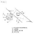
- Fig. 1 is an explanatory view of an RFID detection apparatus 1.
- an article 27 is placed on a stage 21.
- the article 27 has a RFID tag 25 attached thereto.
- the RFID tag 25 includes an antenna and an IC.
- the IC of the RFID tag 25 has a storage section that stores proper information such as an ID, which is identification information, and a name and specification of the article, which are information on the article.
- the RFID detection apparatus 1 is placed which can read the RFID tag 25 existing within a detection area R.
- the RFID detection apparatus 1 includes an antenna 10, a control section 13, and a storage section 15.
- the antenna 10 includes a three-element array antenna which can adjust its directional orientations.
- the control section 13 includes a CPU, a ROM, and a RAM, and performs control operations and computations according to a program such as an RFID tag direction detection program.
- the storage section 15 includes a storage device such as a nonvolatile memory or a hard disk, and stores a program and information (data).
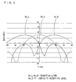
- Fig. 2 is a graph showing respective reception levels in different directional orientations when the RFID detection apparatus 1 reads information from the RFID tag 25.
- a longitudinal axis indicates a reception level (Gain) in units of decibel (dB).
- a lateral axis indicates an angle in units of degree (deg).
- a reception level Rx_L plotted in Fig. 2 indicates how much reception levels in decibels are obtained in given directions where the front side of the antenna 10 is 0°, when the directional orientation (angle ⁇ ) of the antenna 10 is set to -35°.
- a reception level Rx_C plotted in Fig. 2 indicates how much reception levels in decibels are obtained in given directions where the front side of the antenna 10 is 0°, when the directional orientation (angle ⁇ ) of the antenna 10 is set to 0°.
- a reception level Rx_R plotted in Fig. 2 indicates how much reception levels in decibels are obtained in given directions where the front side of the antenna 10 is 0°, when the directional orientation (angle ⁇ ) of the antenna 10 is set to 35°.
- reception level Rx_L can be expressed by the following equation (Equation 3).
- relational equations in logarithmic form and antilogarithmic form are expressed by the following equations (Equations 1 and 2).
- Rx_L in logarithmic form Rx_L Pt + Dt ⁇ - Loss + D_L ⁇
- Pt is a transmission power of the tag
- Loss is a free space loss
- Dt( ⁇ ) is a directional gain of the tag
- D_L( ⁇ ) is a leftward directional gain
- Rx_L in antilogarithmic form Rx_L ⁇ Pt ⁇ ⁇ Dt ⁇ ⁇ ⁇ ⁇ / 4 ⁇ ⁇ D 2 ⁇ D_L ⁇ ⁇
- Pt' is a transmission power of the tag
- D is a communication distance
- Dt'( ⁇ ) is a directional gain of the tag
- D_L'( ⁇ ) is a leftward directional gain.
- Equation 5 by performing subtraction or division with respect to the equations for reception levels in different directional orientations, a function having only ⁇ irrelevant to distances and performance of the tag (reflected power and directional gains of the tag) is obtained.
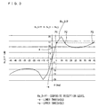
- a longitudinal axis indicates the composite reception level Rx_Diff (Gain) in units of decibel (dB).
- a lateral axis indicates an angle in units of degree (deg).
- the composite reception level Rx_Diff is expressed in a graph form that appears to be a linear function at about 0°, which is near the front side of the antenna 10. Note that the composite reception level Rx_Diff at angles outside about ⁇ 10° is not expressed as a linear function because of a side lobe effect.
- the composite reception level Rx_Diff for the RFID tag 25 satisfies a condition given below with use of thresholds -a and a, the existence direction of the RFID tag 25 is easily found by a linear function.
- the condition is expressed by the following equation: - a ⁇ Rx_Diff ⁇ a where -a is a lower threshold and a is an upper threshold.
- This problem can be coped with by changing an angle of the directional orientation.
- Fig. 4 shows a graph of a composite reception level RX_Diff when the directional orientation corresponding to the reception level Rx_L is changed to 0° while the directional orientation corresponding to the reception level Rx_R is remained unchanged at 35°.
- the obtained composite reception level Rx_Diff is expressed as a function similar to a linear function (a function with continuously increasing or decreasing values). That is, in this example, from the detection results shown in Fig. 3 , it is clear that the RFID tag 25 exists on the right side from the center position. Therefore, an angle of the directional orientation corresponding to the reception level Rx_L to be measured on the left side from the center position is changed to 0° by rightward shift. In this state, the composite reception level Rx_Diff is found. Since it has been already clear that the RFID tag 25 exists on the right side from the center position, the composite reception level Rx_Diff is plotted as a function similar to a linear function when only values on the right side of 0° are seen.
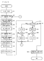
- the control section 13 performs initial setting (step S1) by assigning an initial value (e.g.- 50°) to an angle L of a first direction and then storing the angle L in the storage section 15, and by assigning an initial value (e.g. 50°) to an angle R of a second direction and then storing the angle R in the storage section 15.
- an initial value e.g.- 50°
- an initial value e.g. 50°
- the control section 13 sets the angle of the directional orientation of the antenna 10 to the angle L of the first direction (step S2), and then issues a read command to a given RFID tag 25 (step S3).
- the read command should be such a command that designates an ID that is identification information and requests for a response from only an RFID tag 25 with the designated ID.
- the control section 13 calculates a reception level of a response signal (step S4), and then stores the reception level thus calculated as the reception level Rx_L in the storage section 15 (step S5).
- the control section 13 sets the angle of the directional orientation of the antenna 10 to the angle R of the second direction (step S6), and then issues a read command to the given RFID tag 25 (step S7).
- the read command should be such a command that designates the same ID as designated in step S3 and requests for a response from only an RFID tag 25 with the designated ID.
- the control section 13 calculates a reception level of a response signal (step S8), and then stores the reception level thus calculated as the reception level Rx_R in the storage section 15 (step S9).
- the control section 13 performs difference operation (subtraction for the logarithmic form and division for the antilogarithmic form) for subtracting the reception level Rx_L from the reception level Rx_R, and then stores the operation result as the composite reception level Rx_Diff in the storage section 15 (step S10).
- the control section 13 determines whether the composite reception level Rx_Diff falls within the preset threshold range from -a to +a, whether the composite reception level Rx_Diff is lower than -a, and whether the composite reception level Rx_Diff is greater than +a, so as to roughly determine the incoming direction (step S11). In this process, it is possible to roughly determine whether the RFID tag 25 exists in a centerward direction (within a range of given angles, e.g. a range of angles from -4° to + 4°), in a leftward direction (on the left side with respect to a given angle, e.g. on the left side with respect to the angle of -4°), or in a rightward direction (on the right side with respect to a given angle, e.g. on the right side with respect to the angle of + 4°).
- a centerward direction within a range of given angles, e.g. a range of angles from -4° to + 4°
- a leftward direction on the left side with respect
- the control section 13 determines that the RFID tag 25 exists on the right side with respect to the centerward direction, and the control section 13 then changes the angle L of the first direction to the right by a predetermined angle (e.g. 10°) (step S12). That is, while the angle R indicating rightward directional orientation is fixed, the angle L indicating leftward directional orientation is changed to the right, whereby the difference in angle between the first and second directions is reduced, and a detection coverage is changed to the right as a whole.
- a predetermined angle e.g. 10°
- the control section 13 determines whether or not the angle L is equal to the angle R. If the angle L is not equal to the angle R (No in step S13), the control section 13 returns the process to step S2 and repeats the incoming direction estimating process (steps S2 through S11).
- step S13 If the angle L is equal to the angle R (Yes in step S13), the first direction matches with the second direction.
- the control section 13 therefore changes the angle R of the second direction to the right by a predetermined angle (e.g. 10°) (step S14). Then, the control section 13 returns the process to step S2 and repeats the incoming direction estimating process (steps S2 through S11).
- the control section 13 determines that the RFID tag 25 exists on the left side with respect to the centerward direction, and the control section 13 then changes the angle R of the second direction to the left by a predetermined angle (e.g. -10°) (step S15). That is, while the angle L indicating leftward directional orientation is fixed, the angle R indicating rightward directional orientation is changed to the left, whereby the difference in angle between the first and second directions is reduced, and a detection coverage is changed to the left as a whole.
- a predetermined angle e.g. -10°
- the control section 13 determines whether or not the angle L is equal to the angle R. If the angle L is not equal to the angle R (No in step S16), the control section 13 returns the process to step S2 and repeats the incoming direction estimating process (steps S2 through S11).
- step S16 If the angle L is equal to the angle R (Yes in step S16), the first direction matches with the second direction.
- the control section 13 therefore changes the angle L of the first direction to the left by a predetermined angle (e.g. -10°) (step S17). Then, the control section 13 returns the process to step S2 and repeats the incoming direction estimating process (steps S2 through S11).
- a predetermined angle e.g. -10°
- the control section 13 performs an incoming direction calculating process of calculating incoming direction X of a signal from the RFID tag 25 when viewed from the antenna 10 (step S18).
- the correction equation F(Rx_Diff) in the above equation can be realized by a function, such as a linear function, a quadratic function, or a cubic function, by which an angle can be calculated as a solution when a value of the composite reception level Rx_Diff is substituted for one valuable.
- the function is not the only possibility. Alternately, the following arrangement may be adopted. For example, data of a table providing values of the composite reception level Rx_Diff and their corresponding angles is pre-stored in the storage section 15 so that a corresponding angle is found with reference to the table.
- the antenna 10 is realized by a three-element array antenna, the directional orientations thereof can be instantaneously changed to given angles, and a process of changing the directional orientations and then repeating the incoming direction estimating process can be performed in a short time.
- the directional orientations are changed until the roughly determined direction of the RFID tag 25 falls within a given range, with respect to the centerward direction, where an angle of the existence direction of the RFID tag 25 can be calculated. This makes it possible to appropriately calculate the existence direction of the RFID tag 25, after adjusting the directional orientations suitably for the existence direction of the RFID tag 25.
- Descriptions of Embodiment 1 assume that no limit is provided for change in directional orientation of the antenna 10.
- Descriptions of Embodiment 2 assumes that a limit is provided for change in directional orientation of the antenna 10 or that the RFID tag 25 is not detected if the RFID tag 25 lies in directions outside the range of angles of the directional orientations.
- Fig. 6 is a flowchart of illustrating the operations that the control section 13 of the RFID detection apparatus 1 of Embodiment 2 performs in accordance with a RFID tag direction detection program so as to obtain the existence direction of the RFID tag 25 (incoming signal direction).
- the other arrangements are the same as those of Embodiment 1, and detailed descriptions thereof are therefore omitted.
- steps S1 through S13 are the same as those of Embodiment 1, and detailed descriptions thereof are therefore omitted.
- step S11 if the composite reception level Rx_Diff is not higher than -a (+a ⁇ in step S11), the control section 13 performs step S15 and then causes the process to proceed to step S13, as in Embodiment 1.
- step S12 or S15 the control section 13 determines whether or not the angle L is equal to the angle R. If the angle L is not equal to the angle R (No in step S13), the control section 13 returns the process to step S2 and then repeats the incoming direction estimating process (steps S2 through S11).
- the control section 13 calculates the incoming direction X by adding a correction equation R to the angle R of the second direction.
- step S11 if the composite reception level Rx_Diff is lower than +a and higher than -a (-a > and +a ⁇ in step S11), the control section 13 performs the same incoming direction calculating process as in Embodiment 1 (step S18).
- Embodiment 1 In a case where the composite reception level Rx_Diff falls within the threshold range, it is possible to detect the existence direction of the RFID tag 25 with the same accuracy as in Embodiment 1. Further, in a case where the RFID tag 25 exists outside the limit of selectable directional orientations of the antenna 10, it is possible to detect an approximate existence direction of the RFID tag 25 with an accuracy lower than the accuracy obtained in the case where the composite reception level Rx_Diff falls within the threshold range.
- the lower threshold is set to -a
- the upper threshold is set to +a so that their absolute values are equal to each other.
- the upper and lower thresholds may be individually set to different values. In this case, the same operation effect can be obtained.
- steps S3 and S7 a command for requesting for the ID in response rather than designating the ID may be issued.
- a desired ID is extracted to perform processing for each ID in the steps following steps S3 and S7. This makes it possible to calculate the existence direction of the ID of interest.
- an angle of one of the directional orientations is changed.
- the angles R and L may be both changed, after which the process is repeated.
- the angles of the directional orientations are changed to appropriate angles while a scanning coverage is changed, and at the time when the appropriate angles are obtained, it is possible to detect the existence direction of the RFID tag 25.
- a noncontact IC medium direction detecting apparatus of the present invention corresponds to the RFID detection apparatus 1 in the embodiment. Similarly, the following will describe correspondences between components in the present invention and components in the foregoing embodiments:
Landscapes
- Engineering & Computer Science (AREA)
- Radar, Positioning & Navigation (AREA)
- Remote Sensing (AREA)
- Physics & Mathematics (AREA)
- General Physics & Mathematics (AREA)
- Computer Networks & Wireless Communication (AREA)
- Radar Systems Or Details Thereof (AREA)
- Geophysics And Detection Of Objects (AREA)
- Image Analysis (AREA)
Abstract
Description
- The present invention relates to a noncontact IC medium direction detecting apparatus, for example,O which detects a direction where a noncontact IC medium exists, a method therefor, a program therefor, and a computer-readable recording medium having the program recorded thereon.
- Noncontact IC media capable of performing communication of information stored therein in a noncontact manner are conventionally utilized. Such noncontact IC media include a medium using a UHF band available for long-distance communication. In most cases, a single-element patch antenna is used as an antenna for communicating with the noncontact IC medium using the UHF band. The single-element patch antenna has a half-power width (beamwidth) as broad as about 70 and therefore has the advantage of reading information from the noncontact IC media in a broad area.
- Meanwhile, there has been proposed a tag communication device that calculates the position of a noncontact IC medium on the basis of estimated incoming direction of a radio wave from the noncontact IC medium (see Patent Literature 1). The tag communication device applies different weights to outputs of antenna elements to detect the intensity of the radio wave in a specific direction.
- However, the tag communication device requires complicated calculations in order to find the direction where one noncontact IC medium exists. In addition, the tag communication device is affected by the presence of a reflective object, which requires correction of direction error caused by the reflected object. Thus, the tag communication device cannot easily realize obtaining of the direction where the noncontact IC medium exists.
-
Patent Literature 1
Japanese Patent Application Publication, Tokukai, No.2006-10345 A (Publication Date: January 12, 2006 - The present invention has been made in view of the foregoing problems, and an object of the present invention is to provide a noncontact IC medium direction detecting apparatus capable of easily obtaining an existence direction of a noncontact IC medium, a method therefor, a program therefor, and a computer-readable recording medium having the program recorded thereon.
- The present invention is characterized by being (i) a noncontact IC medium direction detecting apparatus that includes: receiving means capable of reading a noncontact IC medium in different directional orientations; and information processing means that receives information from the receiving means and performs processing of the information, the information processing means being arranged to perform: a first obtaining process of aiming a directional orientation toward a first direction to obtain a signal level of a signal received from the noncontact IC medium having predetermined identification information; a second obtaining process of aiming another directional orientation toward a second direction to obtain a signal level of a signal received from the noncontact IC medium; a composition process of subjecting the signal levels corresponding to the first and second directions to subtraction operation or division to obtain a composite signal level; and an existence direction determining process of determining whether the composite signal level falls within a preset threshold range to determine whether the noncontact IC medium of interest exists in a predetermined direction defined by the threshold range, (ii) a method therefor, and (iii) a program therefor.
- The noncontact IC medium can be realized by a medium, such as an RF-ID tag, which can store information and perform communication in a noncontact manner. The noncontact IC medium includes a passive type medium which is not provided with a power source and obtains induced electromotive force from an external entity to transmit a response signal, a semi-passive type medium which is provided with a power source and transmits the response signal in response to a request from an external entity, and an active type medium which is provided with a power source and transmits signals at regular intervals.
- The receiving means can be realized by one or more array antennas whose directional patterns can be changed or by a plurality of antennas whose directional pattern cannot be changed.
- The information processing means can be realized by means for performing an operation, such as CPU or MPU.
- The identification information can be information by which the noncontact IC medium can be identified, such as an ID of the RFID tag.
- The composition process can be composition based on subtraction operation for the logarithmic form or division for the antilogarithmic form.
- The existence direction operating process can be arranged to find an angle corresponding to the composite signal level according to a preset function or correspondence table.
- The predetermined function can be realized by a function, such as a linear function, a quadratic function, or a cubic function, by which an angle can be calculated as a solution when a value of the composite signal level is substituted for one valuable.
- The present correspondence table can be realized by a table providing vales of the composite signal level and corresponding angles.
- Note that the noncontact IC medium direction detecting apparatus may be realized by a computer. In this case, the present invention also includes a program for detecting a direction of a noncontact IC medium for the noncontact IC medium direction detecting apparatus, wherein the apparatus is realized by the computer by causing the computer to operate as each of the means, and a computer-readable recording medium having the program recorded thereon.
- The present invention can provide a noncontact IC medium direction detecting apparatus capable of easily obtaining an existence direction of a noncontact IC medium, a method therefor, a program therefor, and a computer-readable recording medium having the program recorded thereon.
-
-
Fig. 1
Fig. 1 is an explanatory view of an RFID detection apparatus. -
Fig. 2
Fig. 2 is a graph showing respective reception levels in different directional orientations. -
Fig. 3
Fig. 3 is a graph of a composite reception level. -
Fig. 4
Fig. 4 is a graph of a composite reception level after a directional orientation has been changed. -
Fig. 5
Fig. 5 is a flowchart of operations performed by a control section. -
Fig. 6
Fig. 6 is a flowchart of operations performed by a control section ofEmbodiment 2. - 1...RFID DETECTION APPARATUS, 10...ANTENNA, 13...CONTROL SECTION, 25...RFID TAG, Rx_L and Rx_R...RECEPTION LEVEL, Rx_Diff...COMPOSITE RECEPTION LEVEL, -a ...LOWER THRESHOLD, +a...UPPER THRESHOLD
- The following will describe an embodiment of the present invention with reference to the drawings.
-
Fig. 1 is an explanatory view of anRFID detection apparatus 1. - In this example, an
article 27 is placed on astage 21. Thearticle 27 has aRFID tag 25 attached thereto. TheRFID tag 25 includes an antenna and an IC. The IC of theRFID tag 25 has a storage section that stores proper information such as an ID, which is identification information, and a name and specification of the article, which are information on the article. - Near the
stage 21, theRFID detection apparatus 1 is placed which can read theRFID tag 25 existing within a detection area R. TheRFID detection apparatus 1 includes anantenna 10, acontrol section 13, and astorage section 15. - The
antenna 10 includes a three-element array antenna which can adjust its directional orientations. - The
control section 13 includes a CPU, a ROM, and a RAM, and performs control operations and computations according to a program such as an RFID tag direction detection program. - The
storage section 15 includes a storage device such as a nonvolatile memory or a hard disk, and stores a program and information (data). - Next, the following will describe the theory of a method for detecting an existence direction of the
RFID tag 25 with use of theRFID detection apparatus 1, regardless of distances and performance of the tag. -
Fig. 2 is a graph showing respective reception levels in different directional orientations when theRFID detection apparatus 1 reads information from theRFID tag 25. In the graph, a longitudinal axis indicates a reception level (Gain) in units of decibel (dB). A lateral axis indicates an angle in units of degree (deg). - A reception level Rx_L plotted in
Fig. 2 indicates how much reception levels in decibels are obtained in given directions where the front side of theantenna 10 is 0°, when the directional orientation (angle θ) of theantenna 10 is set to -35°. - A reception level Rx_C plotted in
Fig. 2 indicates how much reception levels in decibels are obtained in given directions where the front side of theantenna 10 is 0°, when the directional orientation (angle θ) of theantenna 10 is set to 0°. - A reception level Rx_R plotted in
Fig. 2 indicates how much reception levels in decibels are obtained in given directions where the front side of theantenna 10 is 0°, when the directional orientation (angle θ) of theantenna 10 is set to 35°. - Here, the reception level Rx_L can be expressed by the following equation (Equation 3). Note that relational equations in logarithmic form and antilogarithmic form are expressed by the following equations (
Equations 1 and 2).


[B] Rx_L in antilogarithmic form
- Further, the reception level Rx_R can be expressed by the following equation:

[B] Rx_R in antilogarithmic form
- Regarding the foregoing two equations, an operation for element reduction composition operation, i.e. subtraction (difference) for the logarithmic form or division for the antilogarithmic form is performed to determine a composite reception level Rx_Diff. The composite reception level Rx_Diff is expressed by the following equation:

- As expressed in
Equation 5, by performing subtraction or division with respect to the equations for reception levels in different directional orientations, a function having only θ irrelevant to distances and performance of the tag (reflected power and directional gains of the tag) is obtained. - This function is shown in graph form in
Fig. 3 . In the graph, a longitudinal axis indicates the composite reception level Rx_Diff (Gain) in units of decibel (dB). A lateral axis indicates an angle in units of degree (deg). - As shown in the graph, the composite reception level Rx_Diff is expressed in a graph form that appears to be a linear function at about 0°, which is near the front side of the
antenna 10. Note that the composite reception level Rx_Diff at angles outside about ±10° is not expressed as a linear function because of a side lobe effect. - Therefore, if the composite reception level Rx_Diff for the
RFID tag 25 satisfies a condition given below with use of thresholds -a and a, the existence direction of theRFID tag 25 is easily found by a linear function. The condition is expressed by the following equation:
- On the other hand, if the
RFID tag 25 falls outside a threshold range from -a to a, it is impossible to detect a precise existence direction of theRFID tag 25 because of the side lobe effect. That is, as shown inFig. 3 , points P1, P2, and P3 are of equal values of Rx_Diff. Therefore, it is impossible to obtain the existence direction of theRFID tag 25 from Rx_Diff. - This problem can be coped with by changing an angle of the directional orientation.
- Here,
Fig. 4 shows a graph of a composite reception level RX_Diff when the directional orientation corresponding to the reception level Rx_L is changed to 0° while the directional orientation corresponding to the reception level Rx_R is remained unchanged at 35°. - As shown in
Fig. 4 , with the change in the directional orientation, the obtained composite reception level Rx_Diff is expressed as a function similar to a linear function (a function with continuously increasing or decreasing values). That is, in this example, from the detection results shown inFig. 3 , it is clear that theRFID tag 25 exists on the right side from the center position. Therefore, an angle of the directional orientation corresponding to the reception level Rx_L to be measured on the left side from the center position is changed to 0° by rightward shift. In this state, the composite reception level Rx_Diff is found. Since it has been already clear that theRFID tag 25 exists on the right side from the center position, the composite reception level Rx_Diff is plotted as a function similar to a linear function when only values on the right side of 0° are seen. - Next, with reference to a flowchart shown in
Fig. 5 , the following will describe the operations that thecontrol section 13 of theRFID detection apparatus 1 performs in accordance with a RFID tag direction detection program so as to obtain the existence direction of the RFID tag 25 (incoming signal direction) according to the above theory. - The
control section 13 performs initial setting (step S1) by assigning an initial value (e.g.- 50°) to an angle L of a first direction and then storing the angle L in thestorage section 15, and by assigning an initial value (e.g. 50°) to an angle R of a second direction and then storing the angle R in thestorage section 15. At the initial setting, it is preferable that the angles L and R are determined to be centrally symmetrical angles. - The
control section 13 sets the angle of the directional orientation of theantenna 10 to the angle L of the first direction (step S2), and then issues a read command to a given RFID tag 25 (step S3). At this time, the read command should be such a command that designates an ID that is identification information and requests for a response from only anRFID tag 25 with the designated ID. - The
control section 13 calculates a reception level of a response signal (step S4), and then stores the reception level thus calculated as the reception level Rx_L in the storage section 15 (step S5). - The
control section 13 sets the angle of the directional orientation of theantenna 10 to the angle R of the second direction (step S6), and then issues a read command to the given RFID tag 25 (step S7). At this time, the read command should be such a command that designates the same ID as designated in step S3 and requests for a response from only anRFID tag 25 with the designated ID. - The
control section 13 calculates a reception level of a response signal (step S8), and then stores the reception level thus calculated as the reception level Rx_R in the storage section 15 (step S9). - The
control section 13 performs difference operation (subtraction for the logarithmic form and division for the antilogarithmic form) for subtracting the reception level Rx_L from the reception level Rx_R, and then stores the operation result as the composite reception level Rx_Diff in the storage section 15 (step S10). - The
control section 13 determines whether the composite reception level Rx_Diff falls within the preset threshold range from -a to +a, whether the composite reception level Rx_Diff is lower than -a, and whether the composite reception level Rx_Diff is greater than +a, so as to roughly determine the incoming direction (step S11). In this process, it is possible to roughly determine whether theRFID tag 25 exists in a centerward direction (within a range of given angles, e.g. a range of angles from -4° to + 4°), in a leftward direction (on the left side with respect to a given angle, e.g. on the left side with respect to the angle of -4°), or in a rightward direction (on the right side with respect to a given angle, e.g. on the right side with respect to the angle of + 4°). - If the composite reception level Rx_Diff is not lower than +a (+a ≥ in step S11), the
control section 13 determines that theRFID tag 25 exists on the right side with respect to the centerward direction, and thecontrol section 13 then changes the angle L of the first direction to the right by a predetermined angle (e.g. 10°) (step S12). That is, while the angle R indicating rightward directional orientation is fixed, the angle L indicating leftward directional orientation is changed to the right, whereby the difference in angle between the first and second directions is reduced, and a detection coverage is changed to the right as a whole. - The
control section 13 determines whether or not the angle L is equal to the angle R. If the angle L is not equal to the angle R (No in step S13), thecontrol section 13 returns the process to step S2 and repeats the incoming direction estimating process (steps S2 through S11). - If the angle L is equal to the angle R (Yes in step S13), the first direction matches with the second direction. The
control section 13 therefore changes the angle R of the second direction to the right by a predetermined angle (e.g. 10°) (step S14). Then, thecontrol section 13 returns the process to step S2 and repeats the incoming direction estimating process (steps S2 through S11). - If the composite reception level Rx_Diff is not higher than -a (-a ≤ in step S11), the
control section 13 determines that theRFID tag 25 exists on the left side with respect to the centerward direction, and thecontrol section 13 then changes the angle R of the second direction to the left by a predetermined angle (e.g. -10°) (step S15). That is, while the angle L indicating leftward directional orientation is fixed, the angle R indicating rightward directional orientation is changed to the left, whereby the difference in angle between the first and second directions is reduced, and a detection coverage is changed to the left as a whole. - The
control section 13 determines whether or not the angle L is equal to the angle R. If the angle L is not equal to the angle R (No in step S16), thecontrol section 13 returns the process to step S2 and repeats the incoming direction estimating process (steps S2 through S11). - If the angle L is equal to the angle R (Yes in step S16), the first direction matches with the second direction. The
control section 13 therefore changes the angle L of the first direction to the left by a predetermined angle (e.g. -10°) (step S17). Then, thecontrol section 13 returns the process to step S2 and repeats the incoming direction estimating process (steps S2 through S11). - If the composite reception level Rx_Diff is lower than +a and higher than -a (-a > and +a < in step S11), the
control section 13 performs an incoming direction calculating process of calculating incoming direction X of a signal from theRFID tag 25 when viewed from the antenna 10 (step S18). The incoming direction X is calculated by the following equation:
- The correction equation F(Rx_Diff) in the above equation can be realized by a function, such as a linear function, a quadratic function, or a cubic function, by which an angle can be calculated as a solution when a value of the composite reception level Rx_Diff is substituted for one valuable. However, the function is not the only possibility. Alternately, the following arrangement may be adopted. For example, data of a table providing values of the composite reception level Rx_Diff and their corresponding angles is pre-stored in the
storage section 15 so that a corresponding angle is found with reference to the table. - With the above arrangements and operations, it is possible to easily detect the incoming direction of a signal from the
RFID tag 25 and to detect the existence direction of theRFID tag 25. - The
antenna 10 is realized by a three-element array antenna, the directional orientations thereof can be instantaneously changed to given angles, and a process of changing the directional orientations and then repeating the incoming direction estimating process can be performed in a short time. - Moreover, the directional orientations are changed until the roughly determined direction of the
RFID tag 25 falls within a given range, with respect to the centerward direction, where an angle of the existence direction of theRFID tag 25 can be calculated. This makes it possible to appropriately calculate the existence direction of theRFID tag 25, after adjusting the directional orientations suitably for the existence direction of theRFID tag 25. - Descriptions of
Embodiment 1 assume that no limit is provided for change in directional orientation of theantenna 10. Descriptions ofEmbodiment 2 assumes that a limit is provided for change in directional orientation of theantenna 10 or that theRFID tag 25 is not detected if theRFID tag 25 lies in directions outside the range of angles of the directional orientations. -
Fig. 6 is a flowchart of illustrating the operations that thecontrol section 13 of theRFID detection apparatus 1 ofEmbodiment 2 performs in accordance with a RFID tag direction detection program so as to obtain the existence direction of the RFID tag 25 (incoming signal direction). The other arrangements are the same as those ofEmbodiment 1, and detailed descriptions thereof are therefore omitted. - As shown in
Fig. 6 , the operations in steps S1 through S13 are the same as those ofEmbodiment 1, and detailed descriptions thereof are therefore omitted. - In step S11, if the composite reception level Rx_Diff is not higher than -a (+a ≥ in step S11), the
control section 13 performs step S15 and then causes the process to proceed to step S13, as inEmbodiment 1. - After step S12 or S15, the
control section 13 determines whether or not the angle L is equal to the angle R. If the angle L is not equal to the angle R (No in step S13), thecontrol section 13 returns the process to step S2 and then repeats the incoming direction estimating process (steps S2 through S11). - If the angle L is equal to the angle R (Yes in step S13), the orientation directions cannot be changed any longer. Therefore, the
control section 13 calculates the incoming direction X by adding a correction equation R to the angle R of the second direction. The equation used for the calculation is given by:
This makes it possible to detect an approximate incoming direction. - In step S11, if the composite reception level Rx_Diff is lower than +a and higher than -a (-a > and +a < in step S11), the
control section 13 performs the same incoming direction calculating process as in Embodiment 1 (step S18). - With the above arrangements and operations, it is possible to obtain the same effect as in
Embodiment 1. In a case where the composite reception level Rx_Diff falls within the threshold range, it is possible to detect the existence direction of theRFID tag 25 with the same accuracy as inEmbodiment 1. Further, in a case where theRFID tag 25 exists outside the limit of selectable directional orientations of theantenna 10, it is possible to detect an approximate existence direction of theRFID tag 25 with an accuracy lower than the accuracy obtained in the case where the composite reception level Rx_Diff falls within the threshold range. - In the foregoing embodiments, the lower threshold is set to -a, and the upper threshold is set to +a so that their absolute values are equal to each other. However, this is not the only possibility. Alternatively, the upper and lower thresholds may be individually set to different values. In this case, the same operation effect can be obtained.
- Further, in steps S3 and S7, a command for requesting for the ID in response rather than designating the ID may be issued. In this case, only a desired ID is extracted to perform processing for each ID in the steps following steps S3 and S7. This makes it possible to calculate the existence direction of the ID of interest.
- Still further, in steps S12 and S15, an angle of one of the directional orientations is changed. Alternatively, the angles R and L may be both changed, after which the process is repeated. Also in this case, the angles of the directional orientations are changed to appropriate angles while a scanning coverage is changed, and at the time when the appropriate angles are obtained, it is possible to detect the existence direction of the
RFID tag 25. - Note that a remainder (or a quotient) from the directional gains is conclusively required by the equations described in the foregoing embodiments, and the remainder (or the quotient) is obtained as a ratio. Therefore, the foregoing embodiments are described in units of mW or dBm. However, this is not the only possibility. The same result can be obtained even if dBW is used as the unit. Similarly, even with a conversion factor calculated with respect to an isotropic antenna using dBi as the unit as described in the present embodiment, or even with a conversion factor calculated with respect to a dipole antenna using dBd as the unit, which is different from the unit used in the present embodiment, the same result can be obtained.
- A noncontact IC medium direction detecting apparatus of the present invention corresponds to the
RFID detection apparatus 1 in the embodiment. Similarly, the following will describe correspondences between components in the present invention and components in the foregoing embodiments: - receiving means corresponds to the
antenna 10; - information processing means corresponds to the
control section 13; - a noncontact IC medium corresponds to the
RFID tag 25; - a first obtaining process corresponds to steps S2 through S5;
- a repeating process corresponds to steps S2 through S11;
- a second obtaining process corresponds to steps S6 through S9;
- a composition process corresponds to step S10;
- an existence direction determining process corresponds to step S11;
- a direction changing process corresponds to steps S12 and S15;
- an angle obtaining process corresponds to steps S18 and S19;
- signal levels correspond to reception levels Rx_L and Rx_R;
- a composite signal level corresponds to a composite reception level Rx_Diff;
- a threshold range corresponds to a range from -a to +a;
- a first threshold corresponds to -a1;
- a second threshold corresponds to +a;
- a preset function or correspondence table corresponds to
Equation 7 or 8; and - identification information corresponds to the ID. However, the present invention is not limited to the configurations of the foregoing embodiments, and many embodiments can be obtained.
Claims (7)
- A noncontact IC medium direction detecting apparatus, comprising:receiving means capable of reading a noncontact IC medium in different directional orientations; andinformation processing means that receives information from the receiving means and performs processing of the information,the information processing means being arranged to perform:a first obtaining process of aiming a directional orientation toward a first direction to obtain a signal level of a signal received from the noncontact IC medium having predetermined identification information;a second obtaining process of aiming another directional orientation toward a second direction to obtain a signal level of a signal received from the noncontact IC medium;a composition process of subjecting the signal levels corresponding to the first and second directions to subtraction operation or division to obtain a composite signal level; andan existence direction determining process of determining whether the composite signal level falls within a preset threshold range to determine whether the noncontact IC medium of interest exists in a predetermined direction defined by the threshold range.
- The noncontact IC medium direction detecting apparatus according to claim 1, wherein
the information processing means is arranged to perform:when it is determined in the existence direction determining process that the noncontact IC medium does not exist in the predetermined direction,a direction changing process of changing at least one of the first and second directions to a different direction; anda repeating process of, after the change of the direction, repeating (i) at least one of the first and second obtaining processes at least one of which is performed according to a result of the direction changing process, (ii) the composition process, and (iii) the existence direction determining process. - The noncontact IC medium direction detecting apparatus according to claim 2, wherein
the threshold range is set to a range from a first threshold in the first direction to a second threshold in the second direction,
the existence direction determining process is arranged such that if the composite signal level falls outside the threshold range, it is determined whether the composite signal level is below the first threshold or above the second threshold, and
the direction changing process is arranged such that if it is determined in the existence direction determining process that the composite signal level is below the first threshold, an angle of the second direction in the second obtaining process is changed toward the first direction, and if it is determined in the existence direction determining process that the composite signal level is above the second threshold, an angle of the first direction in the first obtaining process is changed toward the second direction. - The noncontact IC medium direction detecting apparatus according to claim 1, 2, or 3, wherein
the information processing means is arranged to perform an angle obtaining process of finding an angle corresponding to the composite signal level according to
a preset function or correspondence table which is related to determination results obtained in the existence direction determining process. - A method for detecting a direction of a noncontact IC medium, using:receiving means capable of reading a noncontact IC medium in different directional orientations; andinformation processing means that receives information from the receiving means and performs processing of the information,the information processing means performing:a first obtaining process of aiming a directional orientation toward a first direction to obtain a signal level of a signal received from the noncontact IC medium having predetermined identification information;a second obtaining process of aiming another directional orientation toward a second direction to obtain a signal level of a signal received from the noncontact IC medium;a composition process of subjecting the signal levels corresponding to the first and second directions to subtraction operation or division to obtain a composite signal level; andan existence direction determining process of determining whether the composite signal level falls within a preset threshold range to determine whether the noncontact IC medium of interest exists in a predetermined direction defined by the threshold range.
- A program for detecting a direction of a noncontact IC medium, the program causing information processing means to perform:a first obtaining process of aiming a directional orientation of receiving means, which is capable of reading a noncontact IC medium in different directional orientations, toward a first direction to obtain a signal level of a signal received from the noncontact IC medium having predetermined identification information;a second obtaining process of aiming another directional orientation of the receiving means toward a second direction to obtain a signal level of a signal received from the noncontact IC medium;a composition process of subjecting the signal levels corresponding to the first and second directions to subtraction operation or division to obtain a composite signal level; andan existence direction determining process of determining whether the composite signal level falls within a preset threshold range to determine whether the noncontact IC medium of interest exists in a predetermined direction defined by the threshold range.
- A computer-readable recording medium having recorded thereon the program for detecting a direction of a noncontact IC medium, the program causing information processing means to perform:a first obtaining process of aiming a directional orientation of receiving means, which is capable of reading a noncontact IC medium in different directional orientations, toward a first direction to obtain a signal level of a signal received from the noncontact IC medium having predetermined identification information;a second obtaining process of aiming another directional orientation of the receiving means toward a second direction to obtain a signal level of a signal received from the noncontact IC medium;a composition process of subjecting the signal levels corresponding to the first and second directions to subtraction operation or division to obtain a composite signal level; andan existence direction determining process of determining whether the composite signal level falls within a preset threshold range to determine whether the noncontact IC medium of interest exists in a predetermined direction defined by the threshold range.
Applications Claiming Priority (2)
| Application Number | Priority Date | Filing Date | Title |
|---|---|---|---|
| JP2007322253A JP4353298B2 (en) | 2007-12-13 | 2007-12-13 | Non-contact IC medium direction detection device and method, and program thereof |
| PCT/JP2008/072014 WO2009075215A1 (en) | 2007-12-13 | 2008-12-04 | Apparatus, method and program for detecting direction of noncontact ic medium and computer-readable recording medium having the program recorded thereon |
Publications (3)
| Publication Number | Publication Date |
|---|---|
| EP2233942A1 true EP2233942A1 (en) | 2010-09-29 |
| EP2233942A4 EP2233942A4 (en) | 2011-09-21 |
| EP2233942B1 EP2233942B1 (en) | 2015-11-25 |
Family
ID=40755459
Family Applications (1)
| Application Number | Title | Priority Date | Filing Date |
|---|---|---|---|
| EP08860424.4A Active EP2233942B1 (en) | 2007-12-13 | 2008-12-04 | Apparatus, method and program for detecting direction of noncontact ic medium and computer-readable recording medium having the program recorded thereon |
Country Status (5)
| Country | Link |
|---|---|
| US (1) | US8547206B2 (en) |
| EP (1) | EP2233942B1 (en) |
| JP (1) | JP4353298B2 (en) |
| CN (1) | CN101889214B (en) |
| WO (1) | WO2009075215A1 (en) |
Families Citing this family (5)
| Publication number | Priority date | Publication date | Assignee | Title |
|---|---|---|---|---|
| JP4285576B1 (en) * | 2007-12-04 | 2009-06-24 | オムロン株式会社 | Non-contact IC medium communication apparatus and method, and program thereof |
| JP4353298B2 (en) | 2007-12-13 | 2009-10-28 | オムロン株式会社 | Non-contact IC medium direction detection device and method, and program thereof |
| JP5327171B2 (en) | 2010-09-15 | 2013-10-30 | オムロン株式会社 | RFID system |
| DE102016213234A1 (en) | 2016-02-12 | 2017-08-31 | Fraunhofer-Gesellschaft zur Förderung der angewandten Forschung e.V. | Device for displaying user information and corresponding method |
| JP6410745B2 (en) * | 2016-02-24 | 2018-10-24 | 三菱電機株式会社 | Angle measuring device |
Family Cites Families (27)
| Publication number | Priority date | Publication date | Assignee | Title |
|---|---|---|---|---|
| US4739328A (en) | 1986-07-14 | 1988-04-19 | Amtech Corporation | System for identifying particular objects |
| US5648767A (en) * | 1994-11-30 | 1997-07-15 | Hughes Aircraft | Transponder detection system and method |
| JPH1048306A (en) * | 1996-07-31 | 1998-02-20 | Hitachi Constr Mach Co Ltd | Tracking device for millimeter-wave antenna mounted on construction and civil engineering machinery |
| JP2950248B2 (en) | 1996-08-28 | 1999-09-20 | 日本電気株式会社 | Antenna tracking control method and device |
| US6107910A (en) * | 1996-11-29 | 2000-08-22 | X-Cyte, Inc. | Dual mode transmitter/receiver and decoder for RF transponder tags |
| KR100199016B1 (en) * | 1996-12-02 | 1999-06-15 | 정선종 | Satellite Tracking Method for Vehicle Mounted Antenna System |
| US6289209B1 (en) * | 1996-12-18 | 2001-09-11 | Micron Technology, Inc. | Wireless communication system, radio frequency communications system, wireless communications method, radio frequency communications method |
| JPH11326479A (en) | 1998-05-07 | 1999-11-26 | Nec Eng Ltd | Step tracking device and its method and recording medium recorded with its control program |
| US6427913B1 (en) * | 1998-09-11 | 2002-08-06 | Key-Trak, Inc. | Object control and tracking system with zonal transition detection |
| JP4166401B2 (en) | 2000-02-17 | 2008-10-15 | 松下電器産業株式会社 | Reception directivity control method, antenna apparatus, and mobile communication base station and mobile station using the same |
| CN1280640C (en) | 2000-06-05 | 2006-10-18 | Tc许可有限公司 | Method and apparatus for determining the direction of a transponder in a modulated backscatter communication system |
| WO2002075355A1 (en) * | 2001-03-15 | 2002-09-26 | Fujitsu Ten Limited | Signal processing method for scanning radar |
| JP3784327B2 (en) | 2002-01-18 | 2006-06-07 | 三菱電機株式会社 | Ranging radar equipment |
| JP2003344518A (en) | 2002-05-23 | 2003-12-03 | Tokai Univ | Target tracking system and target tracking method |
| KR100402233B1 (en) * | 2002-06-11 | 2003-10-17 | Digitalsis Co Ltd | Apparatus and method for arbitrating communication between transponders having controller and plural mobile objects |
| JP4110998B2 (en) | 2003-02-21 | 2008-07-02 | ブラザー工業株式会社 | Communication system and interrogator included in communication system |
| GB2410867B (en) * | 2004-02-06 | 2009-04-08 | Btg Int Ltd | Selection and arbitration method and system |
| JP4123195B2 (en) * | 2004-06-22 | 2008-07-23 | オムロン株式会社 | Tag communication device, tag communication device control method, tag communication control program, and tag communication management system |
| KR100682869B1 (en) * | 2004-10-15 | 2007-02-15 | 삼성전기주식회사 | Location tracking system and method |
| US20060197652A1 (en) * | 2005-03-04 | 2006-09-07 | International Business Machines Corporation | Method and system for proximity tracking-based adaptive power control of radio frequency identification (RFID) interrogators |
| JP2007033415A (en) | 2005-07-29 | 2007-02-08 | Murata Mfg Co Ltd | Radar apparatus |
| JP2007306484A (en) * | 2006-05-15 | 2007-11-22 | Omron Corp | Tag communication system, interference prevention method, and tag communication control apparatus |
| JP2008003007A (en) | 2006-06-23 | 2008-01-10 | Fujitsu Ltd | Individual recognition method and apparatus, individual recognition range adjustment method, and program |
| KR100859093B1 (en) * | 2007-04-30 | 2008-09-17 | 광주과학기술원 | Navigation device and method using RFCID |
| US7884712B2 (en) * | 2007-05-08 | 2011-02-08 | Awarepoint Corporation | Wireless tracking system and method utilizing tags with variable power level transmissions |
| US8451098B2 (en) * | 2007-08-05 | 2013-05-28 | Intel Corporation | Switchable active-passive RFID tag |
| JP4353298B2 (en) | 2007-12-13 | 2009-10-28 | オムロン株式会社 | Non-contact IC medium direction detection device and method, and program thereof |
-
2007
- 2007-12-13 JP JP2007322253A patent/JP4353298B2/en not_active Expired - Fee Related
-
2008
- 2008-12-04 WO PCT/JP2008/072014 patent/WO2009075215A1/en not_active Ceased
- 2008-12-04 CN CN200880119748.6A patent/CN101889214B/en active Active
- 2008-12-04 US US12/746,047 patent/US8547206B2/en active Active
- 2008-12-04 EP EP08860424.4A patent/EP2233942B1/en active Active
Also Published As
| Publication number | Publication date |
|---|---|
| JP2009145177A (en) | 2009-07-02 |
| CN101889214A (en) | 2010-11-17 |
| CN101889214B (en) | 2014-08-20 |
| EP2233942A4 (en) | 2011-09-21 |
| US8547206B2 (en) | 2013-10-01 |
| US20100271181A1 (en) | 2010-10-28 |
| JP4353298B2 (en) | 2009-10-28 |
| WO2009075215A1 (en) | 2009-06-18 |
| EP2233942B1 (en) | 2015-11-25 |
Similar Documents
| Publication | Publication Date | Title |
|---|---|---|
| JP4123195B2 (en) | Tag communication device, tag communication device control method, tag communication control program, and tag communication management system | |
| US7602293B2 (en) | Interrogator for RFID tag | |
| US10133888B2 (en) | Data reader and positioning system | |
| EP2233942B1 (en) | Apparatus, method and program for detecting direction of noncontact ic medium and computer-readable recording medium having the program recorded thereon | |
| US9244162B2 (en) | Method, system and computer program product for ranging RFID tags | |
| JP2006010345A5 (en) | ||
| EP2410610A1 (en) | Antenna device and communication device | |
| US20080129461A1 (en) | Radio Frequency Identification Reader and Method of Operating the Same | |
| US8456281B2 (en) | Non-contact IC medium communication device | |
| KR102709853B1 (en) | Method for determinig optimal beam and an electronic device thereof | |
| US10044112B2 (en) | Variable antenna and apparatus for detecting radio signal | |
| JP2013061151A (en) | Radio tag reader and monitor system | |
| US20120155311A1 (en) | Apparatus and method for determining position of target object in wlan environment | |
| JP7095325B2 (en) | Wireless tag reader | |
| JP6292151B2 (en) | Method for estimating moisture content | |
| KR102226690B1 (en) | LOCATION ESTIMATION METHOD AND APPARATUS FOR IoT DEVICE BASED ON BEACON SIGNAL | |
| EP3872682B1 (en) | Reader and method of operating a reader | |
| JP2021032599A (en) | Wireless tag reader | |
| KR101757196B1 (en) | Radio Frequency Identification Reader | |
| EP3872680B1 (en) | System comprising an infoprmation processing device, and method | |
| KR20240039078A (en) | Dual band rfid tag, rfid sensor tag device having the same. and method for calibrating sensing value output rfid sensor tag device | |
| KR20240039077A (en) | Dual band rfid tag, and sensing data processing devive having same | |
| US20200356737A1 (en) | Wireless tag system and wireless communication area shaping method |
Legal Events
| Date | Code | Title | Description |
|---|---|---|---|
| PUAI | Public reference made under article 153(3) epc to a published international application that has entered the european phase |
Free format text: ORIGINAL CODE: 0009012 |
|
| 17P | Request for examination filed |
Effective date: 20100614 |
|
| AK | Designated contracting states |
Kind code of ref document: A1 Designated state(s): AT BE BG CH CY CZ DE DK EE ES FI FR GB GR HR HU IE IS IT LI LT LU LV MC MT NL NO PL PT RO SE SI SK TR |
|
| AX | Request for extension of the european patent |
Extension state: AL BA MK RS |
|
| DAX | Request for extension of the european patent (deleted) | ||
| A4 | Supplementary search report drawn up and despatched |
Effective date: 20110822 |
|
| RIC1 | Information provided on ipc code assigned before grant |
Ipc: G01S 13/74 20060101ALI20110816BHEP Ipc: G06K 17/00 20060101ALI20110816BHEP Ipc: H04B 5/02 20060101ALI20110816BHEP Ipc: H04B 1/59 20060101ALI20110816BHEP Ipc: G01S 3/16 20060101AFI20110816BHEP |
|
| 17Q | First examination report despatched |
Effective date: 20120413 |
|
| GRAP | Despatch of communication of intention to grant a patent |
Free format text: ORIGINAL CODE: EPIDOSNIGR1 |
|
| INTG | Intention to grant announced |
Effective date: 20150612 |
|
| GRAS | Grant fee paid |
Free format text: ORIGINAL CODE: EPIDOSNIGR3 |
|
| GRAA | (expected) grant |
Free format text: ORIGINAL CODE: 0009210 |
|
| RIN1 | Information on inventor provided before grant (corrected) |
Inventor name: NOGAMI, HIDEKATSU |
|
| AK | Designated contracting states |
Kind code of ref document: B1 Designated state(s): AT BE BG CH CY CZ DE DK EE ES FI FR GB GR HR HU IE IS IT LI LT LU LV MC MT NL NO PL PT RO SE SI SK TR |
|
| REG | Reference to a national code |
Ref country code: GB Ref legal event code: FG4D |
|
| REG | Reference to a national code |
Ref country code: CH Ref legal event code: EP |
|
| REG | Reference to a national code |
Ref country code: AT Ref legal event code: REF Ref document number: 762873 Country of ref document: AT Kind code of ref document: T Effective date: 20151215 |
|
| REG | Reference to a national code |
Ref country code: IE Ref legal event code: FG4D |
|
| REG | Reference to a national code |
Ref country code: DE Ref legal event code: R096 Ref document number: 602008041324 Country of ref document: DE |
|
| REG | Reference to a national code |
Ref country code: LT Ref legal event code: MG4D |
|
| REG | Reference to a national code |
Ref country code: NL Ref legal event code: MP Effective date: 20160225 |
|
| REG | Reference to a national code |
Ref country code: AT Ref legal event code: MK05 Ref document number: 762873 Country of ref document: AT Kind code of ref document: T Effective date: 20151125 |
|
| PG25 | Lapsed in a contracting state [announced via postgrant information from national office to epo] |
Ref country code: HR Free format text: LAPSE BECAUSE OF FAILURE TO SUBMIT A TRANSLATION OF THE DESCRIPTION OR TO PAY THE FEE WITHIN THE PRESCRIBED TIME-LIMIT Effective date: 20151125 Ref country code: NL Free format text: LAPSE BECAUSE OF FAILURE TO SUBMIT A TRANSLATION OF THE DESCRIPTION OR TO PAY THE FEE WITHIN THE PRESCRIBED TIME-LIMIT Effective date: 20151125 Ref country code: IS Free format text: LAPSE BECAUSE OF FAILURE TO SUBMIT A TRANSLATION OF THE DESCRIPTION OR TO PAY THE FEE WITHIN THE PRESCRIBED TIME-LIMIT Effective date: 20160325 Ref country code: NO Free format text: LAPSE BECAUSE OF FAILURE TO SUBMIT A TRANSLATION OF THE DESCRIPTION OR TO PAY THE FEE WITHIN THE PRESCRIBED TIME-LIMIT Effective date: 20160225 Ref country code: LT Free format text: LAPSE BECAUSE OF FAILURE TO SUBMIT A TRANSLATION OF THE DESCRIPTION OR TO PAY THE FEE WITHIN THE PRESCRIBED TIME-LIMIT Effective date: 20151125 Ref country code: ES Free format text: LAPSE BECAUSE OF FAILURE TO SUBMIT A TRANSLATION OF THE DESCRIPTION OR TO PAY THE FEE WITHIN THE PRESCRIBED TIME-LIMIT Effective date: 20151125 |
|
| PG25 | Lapsed in a contracting state [announced via postgrant information from national office to epo] |
Ref country code: BE Free format text: LAPSE BECAUSE OF NON-PAYMENT OF DUE FEES Effective date: 20151231 Ref country code: FI Free format text: LAPSE BECAUSE OF FAILURE TO SUBMIT A TRANSLATION OF THE DESCRIPTION OR TO PAY THE FEE WITHIN THE PRESCRIBED TIME-LIMIT Effective date: 20151125 Ref country code: AT Free format text: LAPSE BECAUSE OF FAILURE TO SUBMIT A TRANSLATION OF THE DESCRIPTION OR TO PAY THE FEE WITHIN THE PRESCRIBED TIME-LIMIT Effective date: 20151125 Ref country code: LV Free format text: LAPSE BECAUSE OF FAILURE TO SUBMIT A TRANSLATION OF THE DESCRIPTION OR TO PAY THE FEE WITHIN THE PRESCRIBED TIME-LIMIT Effective date: 20151125 Ref country code: GR Free format text: LAPSE BECAUSE OF FAILURE TO SUBMIT A TRANSLATION OF THE DESCRIPTION OR TO PAY THE FEE WITHIN THE PRESCRIBED TIME-LIMIT Effective date: 20160226 Ref country code: PT Free format text: LAPSE BECAUSE OF FAILURE TO SUBMIT A TRANSLATION OF THE DESCRIPTION OR TO PAY THE FEE WITHIN THE PRESCRIBED TIME-LIMIT Effective date: 20160325 Ref country code: PL Free format text: LAPSE BECAUSE OF FAILURE TO SUBMIT A TRANSLATION OF THE DESCRIPTION OR TO PAY THE FEE WITHIN THE PRESCRIBED TIME-LIMIT Effective date: 20151125 Ref country code: SE Free format text: LAPSE BECAUSE OF FAILURE TO SUBMIT A TRANSLATION OF THE DESCRIPTION OR TO PAY THE FEE WITHIN THE PRESCRIBED TIME-LIMIT Effective date: 20151125 |
|
| PG25 | Lapsed in a contracting state [announced via postgrant information from national office to epo] |
Ref country code: IT Free format text: LAPSE BECAUSE OF FAILURE TO SUBMIT A TRANSLATION OF THE DESCRIPTION OR TO PAY THE FEE WITHIN THE PRESCRIBED TIME-LIMIT Effective date: 20151125 Ref country code: CZ Free format text: LAPSE BECAUSE OF FAILURE TO SUBMIT A TRANSLATION OF THE DESCRIPTION OR TO PAY THE FEE WITHIN THE PRESCRIBED TIME-LIMIT Effective date: 20151125 |
|
| REG | Reference to a national code |
Ref country code: CH Ref legal event code: PL |
|
| REG | Reference to a national code |
Ref country code: DE Ref legal event code: R097 Ref document number: 602008041324 Country of ref document: DE |
|
| PG25 | Lapsed in a contracting state [announced via postgrant information from national office to epo] |
Ref country code: EE Free format text: LAPSE BECAUSE OF FAILURE TO SUBMIT A TRANSLATION OF THE DESCRIPTION OR TO PAY THE FEE WITHIN THE PRESCRIBED TIME-LIMIT Effective date: 20151125 Ref country code: DK Free format text: LAPSE BECAUSE OF FAILURE TO SUBMIT A TRANSLATION OF THE DESCRIPTION OR TO PAY THE FEE WITHIN THE PRESCRIBED TIME-LIMIT Effective date: 20151125 Ref country code: SK Free format text: LAPSE BECAUSE OF FAILURE TO SUBMIT A TRANSLATION OF THE DESCRIPTION OR TO PAY THE FEE WITHIN THE PRESCRIBED TIME-LIMIT Effective date: 20151125 Ref country code: RO Free format text: LAPSE BECAUSE OF FAILURE TO SUBMIT A TRANSLATION OF THE DESCRIPTION OR TO PAY THE FEE WITHIN THE PRESCRIBED TIME-LIMIT Effective date: 20151125 |
|
| REG | Reference to a national code |
Ref country code: IE Ref legal event code: MM4A |
|
| PG25 | Lapsed in a contracting state [announced via postgrant information from national office to epo] |
Ref country code: MC Free format text: LAPSE BECAUSE OF FAILURE TO SUBMIT A TRANSLATION OF THE DESCRIPTION OR TO PAY THE FEE WITHIN THE PRESCRIBED TIME-LIMIT Effective date: 20151125 |
|
| PLBE | No opposition filed within time limit |
Free format text: ORIGINAL CODE: 0009261 |
|
| REG | Reference to a national code |
Ref country code: FR Ref legal event code: ST Effective date: 20160831 |
|
| STAA | Information on the status of an ep patent application or granted ep patent |
Free format text: STATUS: NO OPPOSITION FILED WITHIN TIME LIMIT |
|
| GBPC | Gb: european patent ceased through non-payment of renewal fee |
Effective date: 20160225 |
|
| PG25 | Lapsed in a contracting state [announced via postgrant information from national office to epo] |
Ref country code: LI Free format text: LAPSE BECAUSE OF NON-PAYMENT OF DUE FEES Effective date: 20151231 Ref country code: IE Free format text: LAPSE BECAUSE OF NON-PAYMENT OF DUE FEES Effective date: 20151204 Ref country code: CH Free format text: LAPSE BECAUSE OF NON-PAYMENT OF DUE FEES Effective date: 20151231 |
|
| 26N | No opposition filed |
Effective date: 20160826 |
|
| PG25 | Lapsed in a contracting state [announced via postgrant information from national office to epo] |
Ref country code: FR Free format text: LAPSE BECAUSE OF NON-PAYMENT OF DUE FEES Effective date: 20160125 Ref country code: SI Free format text: LAPSE BECAUSE OF FAILURE TO SUBMIT A TRANSLATION OF THE DESCRIPTION OR TO PAY THE FEE WITHIN THE PRESCRIBED TIME-LIMIT Effective date: 20151125 |
|
| PG25 | Lapsed in a contracting state [announced via postgrant information from national office to epo] |
Ref country code: BE Free format text: LAPSE BECAUSE OF FAILURE TO SUBMIT A TRANSLATION OF THE DESCRIPTION OR TO PAY THE FEE WITHIN THE PRESCRIBED TIME-LIMIT Effective date: 20151125 |
|
| PG25 | Lapsed in a contracting state [announced via postgrant information from national office to epo] |
Ref country code: GB Free format text: LAPSE BECAUSE OF NON-PAYMENT OF DUE FEES Effective date: 20160225 |
|
| PG25 | Lapsed in a contracting state [announced via postgrant information from national office to epo] |
Ref country code: BG Free format text: LAPSE BECAUSE OF FAILURE TO SUBMIT A TRANSLATION OF THE DESCRIPTION OR TO PAY THE FEE WITHIN THE PRESCRIBED TIME-LIMIT Effective date: 20151125 Ref country code: HU Free format text: LAPSE BECAUSE OF FAILURE TO SUBMIT A TRANSLATION OF THE DESCRIPTION OR TO PAY THE FEE WITHIN THE PRESCRIBED TIME-LIMIT; INVALID AB INITIO Effective date: 20081204 |
|
| PG25 | Lapsed in a contracting state [announced via postgrant information from national office to epo] |
Ref country code: CY Free format text: LAPSE BECAUSE OF FAILURE TO SUBMIT A TRANSLATION OF THE DESCRIPTION OR TO PAY THE FEE WITHIN THE PRESCRIBED TIME-LIMIT Effective date: 20151125 |
|
| PG25 | Lapsed in a contracting state [announced via postgrant information from national office to epo] |
Ref country code: MT Free format text: LAPSE BECAUSE OF FAILURE TO SUBMIT A TRANSLATION OF THE DESCRIPTION OR TO PAY THE FEE WITHIN THE PRESCRIBED TIME-LIMIT Effective date: 20151125 Ref country code: TR Free format text: LAPSE BECAUSE OF FAILURE TO SUBMIT A TRANSLATION OF THE DESCRIPTION OR TO PAY THE FEE WITHIN THE PRESCRIBED TIME-LIMIT Effective date: 20151125 |
|
| PG25 | Lapsed in a contracting state [announced via postgrant information from national office to epo] |
Ref country code: LU Free format text: LAPSE BECAUSE OF NON-PAYMENT OF DUE FEES Effective date: 20151204 |
|
| PGFP | Annual fee paid to national office [announced via postgrant information from national office to epo] |
Ref country code: DE Payment date: 20241216 Year of fee payment: 17 |