EP2233908A2 - Honeycomb structure defect inspection device and honeycomb structure defect inspection method - Google Patents
Honeycomb structure defect inspection device and honeycomb structure defect inspection method Download PDFInfo
- Publication number
- EP2233908A2 EP2233908A2 EP10250534A EP10250534A EP2233908A2 EP 2233908 A2 EP2233908 A2 EP 2233908A2 EP 10250534 A EP10250534 A EP 10250534A EP 10250534 A EP10250534 A EP 10250534A EP 2233908 A2 EP2233908 A2 EP 2233908A2
- Authority
- EP
- European Patent Office
- Prior art keywords
- outer peripheral
- peripheral wall
- honeycomb structure
- cells
- elastic member
- Prior art date
- Legal status (The legal status is an assumption and is not a legal conclusion. Google has not performed a legal analysis and makes no representation as to the accuracy of the status listed.)
- Granted
Links
- 230000007547 defect Effects 0.000 title claims abstract description 146
- 238000007689 inspection Methods 0.000 title claims abstract description 70
- 238000000034 method Methods 0.000 title claims description 27
- 230000002093 peripheral effect Effects 0.000 claims abstract description 227
- 238000001514 detection method Methods 0.000 claims abstract description 124
- 238000005192 partition Methods 0.000 claims abstract description 80
- 239000000853 adhesive Substances 0.000 claims 1
- 230000001070 adhesive effect Effects 0.000 claims 1
- 239000010419 fine particle Substances 0.000 description 18
- 238000010586 diagram Methods 0.000 description 10
- 239000002245 particle Substances 0.000 description 8
- 230000035945 sensitivity Effects 0.000 description 7
- 239000011148 porous material Substances 0.000 description 4
- XLYOFNOQVPJJNP-UHFFFAOYSA-N water Substances O XLYOFNOQVPJJNP-UHFFFAOYSA-N 0.000 description 4
- 229920002799 BoPET Polymers 0.000 description 3
- 229910010293 ceramic material Inorganic materials 0.000 description 3
- 239000000463 material Substances 0.000 description 3
- OKTJSMMVPCPJKN-UHFFFAOYSA-N Carbon Chemical compound [C] OKTJSMMVPCPJKN-UHFFFAOYSA-N 0.000 description 2
- 230000008901 benefit Effects 0.000 description 2
- 229920001971 elastomer Polymers 0.000 description 2
- 230000001678 irradiating effect Effects 0.000 description 2
- 239000007788 liquid Substances 0.000 description 2
- XUIMIQQOPSSXEZ-UHFFFAOYSA-N Silicon Chemical compound [Si] XUIMIQQOPSSXEZ-UHFFFAOYSA-N 0.000 description 1
- 239000004809 Teflon Substances 0.000 description 1
- 229920006362 Teflon® Polymers 0.000 description 1
- 230000002159 abnormal effect Effects 0.000 description 1
- 230000004075 alteration Effects 0.000 description 1
- 229910052799 carbon Inorganic materials 0.000 description 1
- 239000000919 ceramic Substances 0.000 description 1
- 238000006243 chemical reaction Methods 0.000 description 1
- 238000002591 computed tomography Methods 0.000 description 1
- 235000009508 confectionery Nutrition 0.000 description 1
- 230000007423 decrease Effects 0.000 description 1
- 230000003247 decreasing effect Effects 0.000 description 1
- 230000007812 deficiency Effects 0.000 description 1
- 230000002950 deficient Effects 0.000 description 1
- 230000000694 effects Effects 0.000 description 1
- 238000005516 engineering process Methods 0.000 description 1
- 229910002804 graphite Inorganic materials 0.000 description 1
- 239000010439 graphite Substances 0.000 description 1
- 230000006872 improvement Effects 0.000 description 1
- 238000003780 insertion Methods 0.000 description 1
- 230000037431 insertion Effects 0.000 description 1
- 238000011835 investigation Methods 0.000 description 1
- 238000004519 manufacturing process Methods 0.000 description 1
- 238000005259 measurement Methods 0.000 description 1
- 238000012986 modification Methods 0.000 description 1
- 230000004048 modification Effects 0.000 description 1
- 150000002825 nitriles Chemical class 0.000 description 1
- 239000013618 particulate matter Substances 0.000 description 1
- 230000035699 permeability Effects 0.000 description 1
- 229920002635 polyurethane Polymers 0.000 description 1
- 239000004814 polyurethane Substances 0.000 description 1
- 238000012545 processing Methods 0.000 description 1
- 230000000644 propagated effect Effects 0.000 description 1
- 238000007789 sealing Methods 0.000 description 1
- 229910052710 silicon Inorganic materials 0.000 description 1
- 239000010703 silicon Substances 0.000 description 1
- HBMJWWWQQXIZIP-UHFFFAOYSA-N silicon carbide Chemical compound [Si+]#[C-] HBMJWWWQQXIZIP-UHFFFAOYSA-N 0.000 description 1
- 229910010271 silicon carbide Inorganic materials 0.000 description 1
- 229920002379 silicone rubber Polymers 0.000 description 1
- 239000004071 soot Substances 0.000 description 1
- 230000001629 suppression Effects 0.000 description 1
- 229920003002 synthetic resin Polymers 0.000 description 1
- 239000000057 synthetic resin Substances 0.000 description 1
Images


Classifications
-
- B—PERFORMING OPERATIONS; TRANSPORTING
- B01—PHYSICAL OR CHEMICAL PROCESSES OR APPARATUS IN GENERAL
- B01D—SEPARATION
- B01D46/00—Filters or filtering processes specially modified for separating dispersed particles from gases or vapours
- B01D46/24—Particle separators, e.g. dust precipitators, using rigid hollow filter bodies
- B01D46/2403—Particle separators, e.g. dust precipitators, using rigid hollow filter bodies characterised by the physical shape or structure of the filtering element
- B01D46/2418—Honeycomb filters
-
- B—PERFORMING OPERATIONS; TRANSPORTING
- B01—PHYSICAL OR CHEMICAL PROCESSES OR APPARATUS IN GENERAL
- B01D—SEPARATION
- B01D46/00—Filters or filtering processes specially modified for separating dispersed particles from gases or vapours
- B01D46/42—Auxiliary equipment or operation thereof
-
- B—PERFORMING OPERATIONS; TRANSPORTING
- B01—PHYSICAL OR CHEMICAL PROCESSES OR APPARATUS IN GENERAL
- B01D—SEPARATION
- B01D65/00—Accessories or auxiliary operations, in general, for separation processes or apparatus using semi-permeable membranes
- B01D65/10—Testing of membranes or membrane apparatus; Detecting or repairing leaks
- B01D65/102—Detection of leaks in membranes
-
- B—PERFORMING OPERATIONS; TRANSPORTING
- B01—PHYSICAL OR CHEMICAL PROCESSES OR APPARATUS IN GENERAL
- B01D—SEPARATION
- B01D2279/00—Filters adapted for separating dispersed particles from gases or vapours specially modified for specific uses
- B01D2279/30—Filters adapted for separating dispersed particles from gases or vapours specially modified for specific uses for treatment of exhaust gases from IC Engines
-
- F—MECHANICAL ENGINEERING; LIGHTING; HEATING; WEAPONS; BLASTING
- F01—MACHINES OR ENGINES IN GENERAL; ENGINE PLANTS IN GENERAL; STEAM ENGINES
- F01N—GAS-FLOW SILENCERS OR EXHAUST APPARATUS FOR MACHINES OR ENGINES IN GENERAL; GAS-FLOW SILENCERS OR EXHAUST APPARATUS FOR INTERNAL COMBUSTION ENGINES
- F01N3/00—Exhaust or silencing apparatus having means for purifying, rendering innocuous, or otherwise treating exhaust
- F01N3/02—Exhaust or silencing apparatus having means for purifying, rendering innocuous, or otherwise treating exhaust for cooling, or for removing solid constituents of, exhaust
- F01N3/021—Exhaust or silencing apparatus having means for purifying, rendering innocuous, or otherwise treating exhaust for cooling, or for removing solid constituents of, exhaust by means of filters
- F01N3/022—Exhaust or silencing apparatus having means for purifying, rendering innocuous, or otherwise treating exhaust for cooling, or for removing solid constituents of, exhaust by means of filters characterised by specially adapted filtering structure, e.g. honeycomb, mesh or fibrous
- F01N3/0222—Exhaust or silencing apparatus having means for purifying, rendering innocuous, or otherwise treating exhaust for cooling, or for removing solid constituents of, exhaust by means of filters characterised by specially adapted filtering structure, e.g. honeycomb, mesh or fibrous the structure being monolithic, e.g. honeycombs
-
- G—PHYSICS
- G01—MEASURING; TESTING
- G01N—INVESTIGATING OR ANALYSING MATERIALS BY DETERMINING THEIR CHEMICAL OR PHYSICAL PROPERTIES
- G01N15/00—Investigating characteristics of particles; Investigating permeability, pore-volume or surface-area of porous materials
- G01N15/08—Investigating permeability, pore-volume, or surface area of porous materials
- G01N2015/0846—Investigating permeability, pore-volume, or surface area of porous materials by use of radiation, e.g. transmitted or reflected light
Definitions
- the present invention relates to a honeycomb structure defect inspection device used.to inspect the presence/absence of holes or cracks which are not present in a normal honeycomb structure and which are large as compared with the pore diameters of a honeycomb structure, that is, defects of the honeycomb structure, and a honeycomb structure defect inspection method.
- a large amount of particulate matter (hereinafter referred to as the "PM") made of soot (carbon graphite) and the like is included, and the PM becomes a cause for atmospheric pollution.
- a diesel particulate filter (DPF) for collecting the PM is mounted in an exhaust system of the diesel engine or the like.
- the plugged honeycomb structure is a honeycomb structure comprising a cell structure portion constituted of partition walls disposed to form a plurality of cells extending through the structure in an axial direction and an outer peripheral wall disposed along the outer periphery of the cell structure portion.
- the plugged honeycomb structure one end of each cell of this honeycomb structure is plugged with a plugging portion.
- the cells which are not provided with the plugging portions on an inlet side are provided with the plugging portions on an outlet side, and the cells provided with the plugging portions on the inlet side are not provided with the plugging portions on the outlet side.
- the plugging portions are disposed in a checkered pattern when observed from the end face of the plugged honeycomb structure. According to such an arrangement of the plugging portions, in the plugged honeycomb structure, a gas to be treated flows into the cells from the inlet side, passes through the ceramic porous partition walls which partition the cells while having the PM collected, and is discharged from the other cells on the outlet side.
- the partition wall having a defect such as a large hole, crack, or the like impairs a PM collecting function because the PM passes through the partition wall from the defect portion thereof.
- another type of DPF has a configuration in which a plurality of plugged honeycomb structure segments each having a predetermined size and shape are combined. In this type of DPF, in a case where one plugged honeycomb structure segment has a defect in a partition wall thereof, the whole DPF becomes a defective product. Therefore, the remaining normal plugged honeycomb structure segments included in this DPF are wasted.
- the presence/absence of a defect such as the large hole, crack, or the like in the partition wall of the plugged honeycomb structure is important from the viewpoints of the function and productivity of the plugged honeycomb structure. Therefore, many technologies have been developed in the defect inspection of the partition walls of the plugged honeycomb structure up to now.
- JP-A-2002-357562 discloses a method of introducing fine particles into cells from one end of a plugged honeycomb structure, and observing the behavior of the fine particles passed through partition walls and discharged from the ends of cells other than the cells into which the fine particles have been introduced in the other end of the structure to inspect the presence/absence of defects of the partition walls. According to this inspection method, when a defect such as a large hole, crack, or the like is present in a certain partition wall, the fine particles are discharged from the cell constituted of this partition wall having the defect portion in a state different from that of a cell constituted of normal partition walls.
- JP-A-2004-286703 discloses a method of introducing water particles into cells of a plugged honeycomb structure instead of the above fine particles to inspect the presence/absence of defect portions of partition walls.
- JP-A-2002- 357562 and JP-A-2004-286703 have a poor detection sensitivity of defect portions of partition walls in the vicinity of an outer peripheral wall of a plugged honeycomb structure.
- the outer peripheral wall of the plugged honeycomb structure is also made of a porous ceramic material, and hence a pressure for passing fine particles or water particles through cells leaks out of the outer peripheral wall. The amount of the fine particles or the water particles to be discharged even from the cells constituted of normal partition walls in the vicinity of the outer peripheral wall decreases.
- the present invention has been developed in view of the above problems and aims to provide a honeycomb structure defect inspection device which detects defect portions of partition walls constituting cells in the vicinity of an outer peripheral wall with a satisfactory sensitivity, and a honeycomb structure defect inspection method.
- the present inventor has found a method for suppressing the leakage of a pressure from the outer peripheral wall of the honeycomb structure and has completed the present invention. That is, according to the present invention, there are provided a honeycomb structure defect inspection device and a honeycomb structure defect inspection method as follows.
- a honeycomb structure defect inspection device for a honeycomb structure comprising a cell structure portion constituted of partition walls disposed to form a plurality of cells extending through the structure in an axial direction and an outer peripheral wall disposed along the outer periphery of the cell structure portion
- the honeycomb structure defect inspection device comprising: a defect detection means for introducing a detection medium into cells from one end face of the structure in the axial direction while applying a pressure to the detection medium to detect defects of the partition walls constituting the cells, and detecting the detection medium passed through the cells and discharged from the other end face of the structure to identify the cell constituted of the partition wall having the defect from the dynamic state of the detection medium discharged from the cells in the other end face of the structure; and an outer peripheral wall covering means for covering 35% or more of the outer peripheral wall so as to maintain the pressure which causes the detection medium in the cells to flow toward the other end face, while suppressing the leakage of the pressure from the outer peripheral wall and so as to sufficiently keep the discharge of the detection medium from the cells constituted of the partition
- the outer peripheral wall covering means comprises at least one elastic member that is deformable in accordance with the shape of the outer peripheral wall, and the elastic member is allowed to adhere to the outer peripheral wall to cover the outer peripheral wall.
- the outer peripheral wall covering means comprises at least one elastic member
- an end of the elastic member is brought into contact with another portion of the same elastic member or a portion of another elastic member to form an elastic ring-shaped member having an internal storage space
- the elastic member is allowed to adhere to the outer peripheral wall so that the elastic ring-shaped member covers the outer peripheral wall while the honeycomb structure is received in the storage space of the elastic ring-shaped member.
- the elastic ring-shaped member comprises at least one elastic member having an end thereof provided with convex portions and concave portions, the end of the elastic member is joined with the other end of the same elastic member or an end of another elastic member, among the joined ends of the elastic members, the convex portions at the end on one side are inserted into the concave portions at the end on the other side to form a ring-like shape, and the depths of the convex portions inserted into the concave portions are varied to adjust the size of the storage space and adhesion strength of the elastic member adhering to the outer peripheral wall so that the elastic ring-shaped member covers the outer peripheral wall while the honeycomb structure is received in the storage space.
- a honeycomb structure defect inspection method for a honeycomb structure comprising a cell structure portion constituted of partition walls disposed to form a plurality of cells extending through the structure in an axial direction and an outer peripheral wall disposed along the outer periphery of the cell structure portion, the honeycomb structure defect inspection method comprising: a detection step of introducing a detection medium into cells from one end face of the structure in the axial direction while applying a pressure to the detection medium to detect defects of the partition walls constituting the cells and detecting the detection medium passed through the cells and discharged from the other end face of the structure to identify the cell constituted of the partition wall having the defect from the dynamic state of the detection medium discharged from the cells in the other end face of the structure; and an outer peripheral wall covering step of covering 35% or more of the outer peripheral wall so as to maintain the pressure which causes the detection medium in the cells to flow toward the other end face, while suppressing the leakage of the pressure from the outer peripheral wall and so as to sufficiently keep the discharge of the detection medium from the cells constituted of the partition walls which
- a honeycomb structure defect inspection device of the present invention can detect the defect portions of the partition walls constituting the cells in the vicinity of the outer peripheral wall with a satisfactory sensitivity.
- Fig. 1A is a perspective view of a square post-like plugged honeycomb structure.
- Fig. 1B is a perspective view of a columnar plugged honeycomb structure.
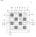
- Fig. 2 is a side view schematically showing that a honeycomb structure defect inspection device of the present invention inspects the presence/absence of defects of the plugged honeycomb structure, and is a see-through diagram showing, by a broken line, the contour of the plugged honeycomb structure which is an inspection target.
- Fig. 3 is a diagram showing that a detection medium is discharged from cells, when the front surface of the end face of the plugged honeycomb structure is observed in the honeycomb structure defect inspection device shown in Fig. 2 .
- Fig. 4 is a diagram schematically showing that the honeycomb structure defect inspection device shown in Fig. 2 detects the defect of the plugged honeycomb structure and including a cross section taken along the A-A' line of Fig. 3 .
- Fig. 5 is a partially sectional view in the vicinity of an outer peripheral wall of the plugged honeycomb structure and is a diagram for explaining the leakage of a pressure from the outer peripheral wall.
- Fig. 6 is a diagram schematically showing that the outer peripheral wall of the plugged honeycomb structure shown in the partial sectional view of Fig. 5 is covered with an elastic member as the outer peripheral wall covering means to suppress the leakage of the pressure from the outer peripheral wall.
- Fig. 7 is a perspective view of an elastic ring-shaped member constituted of two elastic members backed with a rigid member.
- Fig. 8 is a perspective view showing that the elastic ring-shaped member shown in Fig. 7 covers the outer peripheral wall of the plugged honeycomb structure while the plugged honeycomb structure is received in a storage space.
- Fig. 9 is a perspective view of an elastic ring-shaped member constituted of four elastic members.
- Fig. 10 is a perspective view showing that the elastic ring-shaped member shown in Fig. 9 covers the outer peripheral wall of the plugged honeycomb structure while the plugged honeycomb structure is received in a storage space.
- Fig. 11 is a plan view showing that the plugged honeycomb structure is received in the storage space of the elastic ring-shaped member shown in Fig. 9 .
- Fig. 12 is a plan view showing that a plugged honeycomb structure larger than the structure shown in Fig. 11 is received in the storage space of the elastic ring-shaped member shown in Fig. 9 .
- Fig. 13 is a perspective view of an elastic ring-shaped member constituted of two elastic members each having convex and concave portions at the end thereof.
- Fig. 14 is a perspective view showing that the elastic ring-shaped member shown in Fig. 13 covers the outer peripheral wall of the plugged honeycomb structure while the plugged honeycomb structure is received in the storage space.
- Fig. 15 is a plan view showing that the plugged honeycomb structure is received in the storage space of the elastic ring-shaped member shown in Fig. 13 .
- Fig. 16 is a plan view showing that a plugged honeycomb structure larger than the structure shown in Fig. 15 is received in the storage space of the elastic ring-shaped member shown in Fig. 13 .
- a detection medium is introduced into cells of a plugged honeycomb structure, and the detection medium in the cells is passed through partition walls of the structure, whereby the state of the detection medium passed through the partition walls and discharged from the ends of cells other than the cells into which the detection medium has been introduced is observed to inspect whether or not a defect such as a large hole, crack, or the like is present in the partition walls.
- the honeycomb structure defect inspection device of the present invention has a configuration which covers the outer peripheral wall of the honeycomb structure. This improves a sensitivity for identifying the presence/absence of defects in the partition walls constituting the cells in the vicinity of the outer peripheral wall of the honeycomb structure, which has been a theme in a conventional honeycomb structure defect inspection device.
- Fig. 1A is a perspective view of a square post-like plugged honeycomb structure 11
- Fig. 1B is a perspective view of the plugged honeycomb structure 11 having a columnar shape.
- the plugged honeycomb structure 11 has a cell structure portion constituted of partition walls 13 disposed to form a plurality of cells 12 extending through the structure in an axial direction 19 and an outer peripheral wall 14 disposed along the outer periphery of the cell structure portion.
- one end of each cell 12 is plugged with a plugging portion 16.
- the plugging portions 16 are disposed in a checkered pattern when seen from an end face 15 of the plugged honeycomb structure.
- Fig. 3 is a diagram showing that the detection medium 21 is discharged from the ends of the cells 12 which are not provided with the plugging portions 16 in an end face 15b of the plugged honeycomb structure 11 when the front surface of the honeycomb structure defect inspection device 1 shown in Fig. 2 is observed.
- Fig. 4 is a diagram schematically showing that the honeycomb structure defect inspection device 1 shown in Fig. 2 detects the defects of the plugged honeycomb structure 11 and including a cross section taken along the A-A' line of Fig. 3 .
- the defect detection means 2 introduces the detection medium 21 into the cells 12 of the plugged honeycomb structure 11 from one end face 15a in the axial direction 19 while applying a pressure for passing the detection medium 21 through the cells 12.
- the plugged honeycomb structure 11 is disposed so as to align the end face 15a with a mounting surface 26 of a medium introducing portion 22.
- the medium introducing portion 22 introduces the detection medium 21 into the cells 12 from the end face 15a while applying an upward pressure to the detection medium 21.
- the detection medium 21 is introduced into the cells 12 from the one end face 15a, and the introduced detection medium in the cells 12 passes through the partition walls 13 to flow into the adjacent cells 12, and is finally discharged from the other end face 15b.
- the detection medium 21 is introduced into a cell 12b from the end face 15a, the detection medium passes through a partition wall 13a or 13b, flows into a cell 12a or 12c, and is finally discharged from the end face 15b.
- the defect detection means 2 detects the detection medium 21 discharged from the cells 12 which are open in the end face 15b of the plugged honeycomb structure 11.
- a medium detecting portion 23 detects the behavior of the detection medium 21 discharged from the cells 12a and 12c which are open in the end face 15b.
- a large hole 20 is present in a partition wall 13c which separates the cell 12c and a cell 12d, that is, the defect 20 of the partition wall is present. Therefore, a large amount of the detection medium 21 which has flowed through the cell 12d flows into the cell 12c through the hole 20.
- the detection medium 21 has properties to scatter light and where the medium detecting portion 23 is employed in which scattered light generated by irradiating the detection medium 21 discharged from the end face 15b with the light is recorded by a camera.
- the medium detecting portion 23 is employed in which scattered light generated by irradiating the detection medium 21 discharged from the end face 15b with the light is recorded by a camera.
- the end face 15b of the plugged honeycomb structure 11 is observed from the front surface as shown in Fig. 3 , a large amount of the detection medium 21 is discharged from the cell 12c, and hence intense scattered light is observed. Therefore, it can be judged that the partition wall 13 constituting the cell 12c irradiated with the intense scattered light has the defect as compared with the normal cell 12a.
- Examples of "the dynamic state of the detection medium" detected to identify the presence/absence of the defect of the partition wall 13 include comparison of the size of the discharged detection medium 21 and the number of particles thereof with an elapse of time by use of a particle counter, conversion into a discharged amount or concentration based on them, judgment by a speed at which the detection medium 21 flows or the like with a laser Doppler velocity meter (LDV), judgment of luminance by the measurement of the intensity of the scattered light, and judgment of color difference by use of image processing.
- LDV laser Doppler velocity meter
- any configuration can be applied to the defect detection means 2 as long as the means passes the detection medium 21 through the cells 12 of the plugged honeycomb structure 11 and identifies the cell 12 constituted of the partition wall 13 having the defect from the dynamic state of the detection medium 21 discharged from the ends of the cells 12 in the end face 15 of the plugged honeycomb structure 11. This also applies to the specific configuration of the detection medium 21.
- the outer peripheral wall covering means 3 covers a part or all of the outer peripheral wall 14 of the plugged honeycomb structure 11, and suppresses the leakage of the pressure for passing the detection medium 21 through the cells 12 from the outer peripheral wall 14.
- the leakage of the pressure from the outer peripheral wall 14 is suppressed in this manner, whereby the flow of the detection medium 21 in the cells 12 is maintained, and the discharge of the detection medium 21 from the ends of the normal cells 12 constituted of the partition walls 13 which do not have any defect in the vicinity of the outer peripheral wall 14 can sufficiently be kept.
- Fig. 5 schematically shows that the detection medium 21 is introduced into the cells 12 of the plugged honeycomb structure 11 while the outer peripheral wall 14 is not covered with the outer peripheral wall covering means 3.
- the outer peripheral wall 14 of the plugged honeycomb structure 11 is made of a porous material such as a ceramic material, the pressure for passing the detection medium 21 through the cells 12 leaks from the outer peripheral wall 14.
- the cell 12c in the vicinity of the outer peripheral wall 14 has a smaller pressure for causing the detection medium 21 to flow as compared with the cell 12a in the center, and the detection medium 21 is not sufficiently discharged from the end face 15b.
- the detection medium 21 discharged from the end face 15b is not easily detected, and it becomes difficult to judge the presence/absence of the defect in the partition walls 13.
- Fig. 6 is a sectional view schematically showing that the detection medium 21 is introduced into the cells 12 of the plugged honeycomb structure 11 while the outer peripheral wall 14 is covered with the outer peripheral wall covering means 3.
- the outer peripheral wall covering means 3 suppresses the leakage of the pressure from the outer peripheral wall 14, and hence the pressure for causing the detection medium 21 to flow in the cell 12c in the vicinity of the outer peripheral wall 14 covered with the outer peripheral wall covering means 3 is kept at a level which is approximately equal to that in the cells 12a and 12b in the center. Therefore, in the cell 12c shown in Fig. 6 , the detection medium 21 is sufficiently discharged from the end face 15b (the cells 12c of Figs.
- the cell 12c in the vicinity of the outer peripheral wall 14 covered with the outer peripheral wall covering means 3 makes a difference in the dynamic state of the detection medium 21 discharged from the end face 15b between a normal state where the cell is constituted of the partition wall 13 which does not have any defect and an abnormal state where the cell is constituted of the partition wall 13 having the defect, whereby the presence/absence of the defect in the partition walls 13 can be judged.
- the discharge of the detection medium 21 from the cell 12 constituted of the partition wall 13 which does not have any defect in the vicinity of the outer peripheral wall 14 is sufficiently kept means what is relative depending on the detection sensitivity of the detection medium 21 by the defect detection means 2. For example, in a case where the detection sensitivity of the detection medium 21 by the defect detection means 2 is low, when the leakage of the pressure from the outer peripheral wall 14 is strictly suppressed by the outer peripheral wall covering means 3, it can be considered that the discharge of the detection medium 21 from the end face 15b is sufficiently kept.
- the honeycomb structure defect inspection device 1 of the present invention achieves its purpose when the presence/absence of the defects in the partition walls 13 constituting the cells 12 of the plugged honeycomb structure 11 can be judged.
- the outer peripheral wall covering means 3 covers 35% or more of the total area of the outer peripheral wall 14 of the plugged honeycomb structure 11 which is an inspection target, and it is preferable that the means covers 60% or more of the total area of the outer peripheral wall 14.
- the effect of the suppression of the leakage of the pressure from the outer peripheral wall 14 increases, whereby it is more preferable that the ratio of the area of the outer peripheral wall 14 covered with the outer peripheral wall covering means 3 increases with respect to the total area of the outer peripheral wall 14.
- the covering means in a case where the outer peripheral wall covering means 3 covers a part of the outer peripheral wall, the covering means preferably covers the outer peripheral wall 14 so that the cover ratio of a half of the outer peripheral wall 14 on the side of the end face 15a through which the detection medium 21 is introduced is larger than that of a half of the outer peripheral wall 14 on the side of the end face 15b from which the detection medium 21 is discharged.
- the pressure applied to the detection medium 21 to be passed through the cells 12 is kept to be high in the cells 12 in the vicinity of the end face 15a through which the detection medium 21 is introduced, and the detection medium 21 starts passing through the cells 12 with a high initial speed.
- the elastic member 31 provided in the outer peripheral wall covering means 3 to cover the outer peripheral wall 14 is preferably made of a material which does not have any air permeability in order to exert a function of suppressing the leakage of the pressure from the outer peripheral wall 14.
- Examples of the material of the elastic member 31 include a synthetic resin material such as silicon, Teflon, candy rubber or nitrile.
- the elastic member 31 may be a foamed or porous member, but when such a member is used, the surface of the elastic member 31 or the like is preferably covered with a film having high sealing properties so that the outer peripheral wall covering means 3 can suppress the leakage of the pressure from the outer peripheral wall 14.
- Fig. 8 shows that the plugged honeycomb structure 11 is received in the storage space 39 of the elastic ring-shaped member 40 shown in Fig. 7 .
- the elastic member 31 is allowed to adhere to the outer peripheral wall 14 while the plugged honeycomb structure 11 is received in the storage space 39, whereby the outer peripheral wall 14 is covered to suppress the leakage of the pressure from the outer peripheral wall 14.
- the "ring-like shape" of the elastic ring-shaped member 40 mentioned herein is, needless to say, a circular shape and may be a polygonal shape such as a triangular or quadrangular shape, and any shape is allowable as long as the storage space 39 is formed so as to extend through the elastic ring-shaped member 40 and the elastic ring-shaped member 40 can surround the outer peripheral wall 14.
- ends 32a of an L-shaped elastic member 31a are joined with ends 32b of an elastic member 31b having the same L-shape to form a ring-like shape, whereby the storage space 39 having a rectangular parallelepiped shape is formed in the elastic ring-shaped member.
- Fig. 8 shows that the square post-like plugged honeycomb structure 11 is received in the storage space 39 of the elastic ring-shaped member 40 shown in Fig. 7 .
- the elastic members 31a and 31b adhere to the outer peripheral wall 14 to cover the outer peripheral wall 14.
- a plate-like flexuous elastic member 31 (not shown) is wound to join both the ends 32, whereby the elastic ring-shaped member 40 can be formed.
- the plate-like elastic member 31 is wound around the outer peripheral wall 14 of the plugged honeycomb structure 11, whereby the outer peripheral wall 14 can be covered.
- the elastic ring-shaped member 40 shown in Figs. 9 to 11 has the four elastic members 31a to 31d, and ends 32a to 32d of the elastic members 31a to 31d are brought into contact with a portion of another elastic member 31 to form a ring-like shape.
- the end 32a of the elastic member 31a comes in contact with an intermediate portion of the elastic member 31d
- the end 32b of the elastic member 31b comes in contact with an intermediate portion of the elastic member 31a
- the end 32c of the elastic member 31c comes in contact with an intermediate portion of the elastic member 31b
- the end 32d of the elastic member 31d comes in contact with an intermediate portion of the elastic member 31c.
- Fig. 12 shows that the plugged honeycomb structure 11 having a large long-diameter of a cross section perpendicular to the axial direction 19 as compared with the structure shown in Fig. 11 is received in the storage space 39 of the elastic ring-shaped member 40 shown in Fig. 9 to cover the outer peripheral wall 14 when the front surface of the end face 15b of the plugged honeycomb structure 11 is observed.
- Fig. 12 shows that the plugged honeycomb structure 11 having a large long-diameter of a cross section perpendicular to the axial direction 19 as compared with the structure shown in Fig. 11 is received in the storage space 39 of the elastic ring-shaped member 40 shown in Fig. 9 to cover the outer peripheral wall 14 when the front surface of the end face 15b of the plugged honeycomb structure 11 is observed.
- the portion of the same elastic member 31 or the portion of the other elastic member 31 brought into contact with the end 32 of the elastic member 31 is changed to adjust the size of the storage space 39 and the adhesion strength of the elastic member 31 adhering to the outer peripheral wall 14, whereby the plugged honeycomb structure 11 is received in the storage space 39 to cover the outer peripheral wall 14.
- the elastic ring-shaped member 40 shown in Fig. 13 is formed into a ring-like shape by inserting convex portions 33a at the end 32a of the elastic member 31a into concave portions 34b at the end 32b of the other elastic member 31b, and conversely inserting convex portions 33b at the end 32b of the elastic member 31b into concave portions 34a at the end 32a of the other elastic member 31a.
- Fig. 15 is a diagram of the plugged honeycomb structure 11 received in the storage space 39 of the elastic ring-shaped member 40 shown in Fig. 13 when the front surface of the end face 15b of the plugged honeycomb structure 11 is observed.
- the convex portions 33a and 33b are deeply inserted into the concave portions 34b and 34a to reduce the storage space 39, whereby the elastic members 31a and 31b can further adhere to the outer peripheral wall 14 to cover the outer peripheral wall 14.
- the elastic ring-shaped member 40 having the configuration capable of adjusting the size of the storage space 39 has a function of improving adhesiveness between the elastic members 31 and the outer peripheral wall 14 and effectively suppressing the leakage of the pressure from the outer peripheral wall 14.
- Fig. 16 shows that the plugged honeycomb structure 11 having a large long-diameter of a cross section perpendicular to the axial direction 19 as compared with the structure shown in Fig. 15 is received in the storage space 39 of the elastic ring-shaped member 40 shown in Fig. 13 to cover the outer peripheral wall 14 when the front surface of the end face 15 of the plugged honeycomb structure 11 is observed.
- the depths of the convex portions 33a and 33b inserted into the concave portions 34b and 34a can be decreased to enlarge the storage space 39.
- the outer peripheral wall covering means 3 is provided with the elastic member 31 to cover the outer peripheral wall 14, the surface of the elastic member 31 opposite to the surface adhering to the outer peripheral wall 14 is preferably backed with the rigid member 35.
- an elastic ring-shaped member having a technical idea different from the elastic ring-shaped member 40 described above and constituted of a ring-shaped tube expanded by injecting a gas or a liquid into the inside thereof as in a rubber tube used in tires of a bicycle.
- This type of elastic ring-shaped member has an advantage that the plugged honeycomb structure 11 can be received in a ring to adjust the amount of the gas or the liquid to be injected into the tube, thereby easily adjusting the strength of the close attachment between the elastic ring-shaped member and the outer peripheral wall 14.
- a honeycomb structure defect inspection method of the present invention inspects the presence/absence of a defect such as a large hole or crack in the partition walls 13 of the plugged honeycomb structure 11.
- a honeycomb structure defect inspection method of the present invention includes a detection step and an outer peripheral wall covering step.
- the detection medium 21 is introduced through the cells 12 from the one end face 15a of the structure in the axial direction 19 while applying a pressure to the detection medium 21 passed through the cells 12 to detect defects of the partition walls 13 constituting the cells 12, and the detection medium 21 passed through the cells 12 and discharged from the other end face 15b of the structure is detected to identify the cell 12 constituted of the partition wall 13 having a defect from the dynamic state of the detection medium 21 discharged from the cells 12 in the other end face 15b of the structure.
- the outer peripheral wall covering step is a step of covering 35% or more of the outer peripheral wall 14 so as to maintain the pressure to cause the detection medium 21 in the cells 12 to flow toward the end face 15b while suppressing the leakage of the pressure from the outer peripheral wall 14 and to sufficiently keep the discharge of the detection medium 21 from the cells 12 constituted of the partition walls 13 which do not have any defect in the vicinity of the outer peripheral wall 14 in the end face 15b.
- the outer peripheral wall covering step is preferably a step of allowing at least one elastic member 31 which is deformable in accordance with the shape of the outer peripheral wall 14 to adhere to the outer peripheral wall 14 to cover the outer peripheral wall 14.
- the outer peripheral wall covering step using the elastic member 31 has an advantage that it is possible to inspect the plugged honeycomb structure 11 having fluctuations of the shape of the outer peripheral wall 14, for example, warpage, bend and other deformations of the outer peripheral wall 14 generated in an actual production site.
- a structure made of silicon carbide and having a square post-like shape with a length of 200 mm in an axial direction 19 and with a square cross section of 39 mm ⁇ 39 mm perpendicular to the axial direction 19 was used.
- the number of cells per cm 2 of the cross section perpendicular to the axial direction 19 was 40
- partition walls had a thicknesses of 300 ⁇ m
- the outer peripheral wall 14 had a thickness of 510 ⁇ m and a porosity of 50%
- the average pore diameter of partition walls 13 and the outer peripheral wall 14 was 20 ⁇ m
- the size of a hole 20 as a defect generated in the partition wall 13 was a diameter of 0.1 mm.
- the plugged honeycomb structure 11 As the plugged honeycomb structure 11 which was the inspection target, two types of the structures were prepared, that is, a specimen having a defect in the partition wall 13 on the side of an end face 15a into which fine particles 21 as a detection medium 21 flowed, and a specimen having a defect in the partition wall 13 on the side of an end face 15b from which the fine particles 21 were discharged. It is to be noted that defect portions of the partition walls of the plugged honeycomb structures 11 as the specimens were confirmed by a CT scan in advance.
- fine particles 21 having an average particle diameter of 3 to 5 ⁇ m were used as a detection medium 21.
- the fine particles 21 were contained in a gas with a concentration of 300 particles/cm', and the gas containing the fine particles was supplied to the end face 15b side of a plugged honeycomb structure 11 at a flow rate of 14 L/min. and introduced into cells 12.
- the fine particles 21 discharged from the cells 12 were detected from scattered light generated by irradiating the fine particles with light.
- outer peripheral wall covering means 3 two L-shaped elastic members 31 each made of a silicon rubber and having a hardness of 30 degrees and a thickness of 4 mm were combined to form an elastic ring-shaped member 40, and an outer peripheral wall 14 was covered while a plugged honeycomb structure 11 having a square post-like shape as described above was received in a rectangular parallelepiped storage space 39 of the elastic ring-shaped member 40.
- Examples 1 to 9 were divided in accordance with the elastic ring-shaped member 40 as the outer peripheral wall covering means 3 based on a covered place of the outer peripheral wall 14 of the plugged honeycomb structure 11 and the ratio of the area of the covered outer peripheral wall 14 with respect to the total area of the outer peripheral wall 14. Specifically, as shown in Table 1, the outer peripheral wall 14 was covered along a predetermined length from the end face 15 on the inflow side or outflow side of the fine particles 21.
- Example 10 was the same as Example 3 except that the outer peripheral wall covering means 3 having a configuration shown in Figs. 9 and 10 was used, that elastic members 31 constituting the elastic ring-shaped member 40 were made of foamed polyurethane having a porous structure, and that the surface of the elastic member 31 which came in contact with the outer peripheral wall 14 was sealed with a PET film having a thickness of 35 ⁇ m.
- Example 11 was similar to Example 10 except that a plugged honeycomb structure 11 having a square cross section of 42 x 42 mm perpendicular to the axial direction 19 was an inspection target.
- Table 1 how clearly the defects of the partition walls 13 constituting the cells 12 in the vicinity of the outer peripheral wall 14 can be identified is shown in Table 1.
- Table 1 a case where the defects can clearly be identified is shown by a double circle (excellent), a case where the defects can stably be identified is shown by a circle (good), a case where the defects can or cannot be judged is sometimes shown by a triangle (not good, but acceptable), and a case where any defect cannot be identified is shown by a cross (bad).
- Example 1 to 5 the outer peripheral wall 14 at a predetermined ratio from the end face 15a on the inflow side of the plugged honeycomb structure 11 is covered. It is seen from the comparison of the results of Examples 1 to 5 that the degree of the judgment of the defects of the partition walls 13 is excellent as the ratio of the area of the outer peripheral wall 14 covered with the elastic member 31 with respect to the total area of the outer peripheral wall 14 is high.
- the present invention can be used as a device for inspecting the presence/absence of holes or cracks which are not present in a normal honeycomb structure and which are large as compared with the pore diameters of a honeycomb structure, that is, defects of the honeycomb structure.
Landscapes
- Chemical & Material Sciences (AREA)
- Chemical Kinetics & Catalysis (AREA)
- Physics & Mathematics (AREA)
- Geometry (AREA)
- Filtering Of Dispersed Particles In Gases (AREA)
- Investigating Materials By The Use Of Optical Means Adapted For Particular Applications (AREA)
- Exhaust Gas After Treatment (AREA)
- Filtering Materials (AREA)
- Processes For Solid Components From Exhaust (AREA)
Abstract
Description
- The present invention relates to a honeycomb structure defect inspection device used.to inspect the presence/absence of holes or cracks which are not present in a normal honeycomb structure and which are large as compared with the pore diameters of a honeycomb structure, that is, defects of the honeycomb structure, and a honeycomb structure defect inspection method.
- In an exhaust gas discharged from a diesel engine or the like, a large amount of particulate matter (hereinafter referred to as the "PM") made of soot (carbon graphite) and the like is included, and the PM becomes a cause for atmospheric pollution. A diesel particulate filter (DPF) for collecting the PM is mounted in an exhaust system of the diesel engine or the like.
- As the DPF, for example, a plugged honeycomb structure made of a ceramic material is used (e.g., see
JP-A-2001-269585 - In the plugged honeycomb structure used as the DPF, the partition wall having a defect such as a large hole, crack, or the like impairs a PM collecting function because the PM passes through the partition wall from the defect portion thereof. Moreover, another type of DPF has a configuration in which a plurality of plugged honeycomb structure segments each having a predetermined size and shape are combined. In this type of DPF, in a case where one plugged honeycomb structure segment has a defect in a partition wall thereof, the whole DPF becomes a defective product. Therefore, the remaining normal plugged honeycomb structure segments included in this DPF are wasted. As understood from these situations, the presence/absence of a defect such as the large hole, crack, or the like in the partition wall of the plugged honeycomb structure is important from the viewpoints of the function and productivity of the plugged honeycomb structure. Therefore, many technologies have been developed in the defect inspection of the partition walls of the plugged honeycomb structure up to now.
-
JP-A-2002-357562 JP-A-2004-286703 - However, the inspection methods of
JP-A-2002- 357562 JP-A-2004-286703 - The present invention has been developed in view of the above problems and aims to provide a honeycomb structure defect inspection device which detects defect portions of partition walls constituting cells in the vicinity of an outer peripheral wall with a satisfactory sensitivity, and a honeycomb structure defect inspection method.
- To achieve the above object, as a result of intensive investigations, the present inventor has found a method for suppressing the leakage of a pressure from the outer peripheral wall of the honeycomb structure and has completed the present invention. That is, according to the present invention, there are provided a honeycomb structure defect inspection device and a honeycomb structure defect inspection method as follows.
- [1] A honeycomb structure defect inspection device for a honeycomb structure comprising a cell structure portion constituted of partition walls disposed to form a plurality of cells extending through the structure in an axial direction and an outer peripheral wall disposed along the outer periphery of the cell structure portion, the honeycomb structure defect inspection device comprising: a defect detection means for introducing a detection medium into cells from one end face of the structure in the axial direction while applying a pressure to the detection medium to detect defects of the partition walls constituting the cells, and detecting the detection medium passed through the cells and discharged from the other end face of the structure to identify the cell constituted of the partition wall having the defect from the dynamic state of the detection medium discharged from the cells in the other end face of the structure; and an outer peripheral wall covering means for covering 35% or more of the outer peripheral wall so as to maintain the pressure which causes the detection medium in the cells to flow toward the other end face, while suppressing the leakage of the pressure from the outer peripheral wall and so as to sufficiently keep the discharge of the detection medium from the cells constituted of the partition walls which do not have any defect in the vicinity of the outer peripheral wall in the other end face.
- [2] The honeycomb structure defect inspection device according to the above [1], wherein the outer peripheral wall covering means covers the outer peripheral wall so that a cover ratio of a half of the outer peripheral wall on the side of the one end face through which the detection medium is introduced is larger than that of a half of the outer peripheral wall on the side of the other end face from which the detection medium is discharged.
- [3] The honeycomb structure defect inspection device according to the above [1] or [2], wherein the outer peripheral wall covering means comprises at least one elastic member that is deformable in accordance with the shape of the outer peripheral wall, and the elastic member is allowed to adhere to the outer peripheral wall to cover the outer peripheral wall.
- [4] The honeycomb structure defect inspection device according to the above [3], wherein the outer peripheral wall covering means comprises at least one elastic member, an end of the elastic member is brought into contact with another portion of the same elastic member or a portion of another elastic member to form an elastic ring-shaped member having an internal storage space, and the elastic member is allowed to adhere to the outer peripheral wall so that the elastic ring-shaped member covers the outer peripheral wall while the honeycomb structure is received in the storage space of the elastic ring-shaped member.
- [5] The honeycomb structure defect inspection device according to the above [4], wherein the portion of the same elastic member or the portion of another elastic member brought into contact with the end of the elastic member is changed to adjust the size of the storage space and the adhesion strength of the elastic member adhering to the outer peripheral wall so that the elastic ring-shaped member covers the outer peripheral wall while the honeycomb structure is received in the storage space.
- [6] The honeycomb structure defect inspection device according to the above [4], wherein the elastic ring-shaped member comprises at least one elastic member having an end thereof provided with convex portions and concave portions, the end of the elastic member is joined with the other end of the same elastic member or an end of another elastic member, among the joined ends of the elastic members, the convex portions at the end on one side are inserted into the concave portions at the end on the other side to form a ring-like shape, and the depths of the convex portions inserted into the concave portions are varied to adjust the size of the storage space and adhesion strength of the elastic member adhering to the outer peripheral wall so that the elastic ring-shaped member covers the outer peripheral wall while the honeycomb structure is received in the storage space.
- [7] The honeycomb structure defect inspection device according to any one of the above [3] to [6], wherein, in the outer peripheral wall covering means, the surface of the elastic member opposite to the surface thereof adhering to the outer peripheral wall is backed with a rigid member.
- [8] A honeycomb structure defect inspection method for a honeycomb structure comprising a cell structure portion constituted of partition walls disposed to form a plurality of cells extending through the structure in an axial direction and an outer peripheral wall disposed along the outer periphery of the cell structure portion, the honeycomb structure defect inspection method comprising: a detection step of introducing a detection medium into cells from one end face of the structure in the axial direction while applying a pressure to the detection medium to detect defects of the partition walls constituting the cells and detecting the detection medium passed through the cells and discharged from the other end face of the structure to identify the cell constituted of the partition wall having the defect from the dynamic state of the detection medium discharged from the cells in the other end face of the structure; and an outer peripheral wall covering step of covering 35% or more of the outer peripheral wall so as to maintain the pressure which causes the detection medium in the cells to flow toward the other end face, while suppressing the leakage of the pressure from the outer peripheral wall and so as to sufficiently keep the discharge of the detection medium from the cells constituted of the partition walls which do not have any defect in the vicinity of the outer peripheral wall in the other end face.
- [9] The honeycomb structure defect inspection method according to the above [8], wherein, in the outer peripheral wall covering step, at least one elastic member being deformable in accordance with the shape of the outer peripheral wall is allowed to adhere to the outer peripheral wall to cover the outer peripheral wall.
- [10] The honeycomb structure defect inspection method according to the above [8] or [9], which simultaneously performs the detection step and the outer peripheral wall covering step.
- A honeycomb structure defect inspection device of the present invention can detect the defect portions of the partition walls constituting the cells in the vicinity of the outer peripheral wall with a satisfactory sensitivity.
-
Fig. 1A is a perspective view of a square post-like plugged honeycomb structure. -
Fig. 1B is a perspective view of a columnar plugged honeycomb structure. -
Fig. 2 is a side view schematically showing that a honeycomb structure defect inspection device of the present invention inspects the presence/absence of defects of the plugged honeycomb structure, and is a see-through diagram showing, by a broken line, the contour of the plugged honeycomb structure which is an inspection target. -
Fig. 3 is a diagram showing that a detection medium is discharged from cells, when the front surface of the end face of the plugged honeycomb structure is observed in the honeycomb structure defect inspection device shown inFig. 2 . -
Fig. 4 is a diagram schematically showing that the honeycomb structure defect inspection device shown inFig. 2 detects the defect of the plugged honeycomb structure and including a cross section taken along the A-A' line ofFig. 3 . -
Fig. 5 is a partially sectional view in the vicinity of an outer peripheral wall of the plugged honeycomb structure and is a diagram for explaining the leakage of a pressure from the outer peripheral wall. -
Fig. 6 is a diagram schematically showing that the outer peripheral wall of the plugged honeycomb structure shown in the partial sectional view ofFig. 5 is covered with an elastic member as the outer peripheral wall covering means to suppress the leakage of the pressure from the outer peripheral wall. -
Fig. 7 is a perspective view of an elastic ring-shaped member constituted of two elastic members backed with a rigid member. -
Fig. 8 is a perspective view showing that the elastic ring-shaped member shown inFig. 7 covers the outer peripheral wall of the plugged honeycomb structure while the plugged honeycomb structure is received in a storage space. -
Fig. 9 is a perspective view of an elastic ring-shaped member constituted of four elastic members. -
Fig. 10 is a perspective view showing that the elastic ring-shaped member shown inFig. 9 covers the outer peripheral wall of the plugged honeycomb structure while the plugged honeycomb structure is received in a storage space. -
Fig. 11 is a plan view showing that the plugged honeycomb structure is received in the storage space of the elastic ring-shaped member shown inFig. 9 . -
Fig. 12 is a plan view showing that a plugged honeycomb structure larger than the structure shown inFig. 11 is received in the storage space of the elastic ring-shaped member shown inFig. 9 . -
Fig. 13 is a perspective view of an elastic ring-shaped member constituted of two elastic members each having convex and concave portions at the end thereof. -
Fig. 14 is a perspective view showing that the elastic ring-shaped member shown inFig. 13 covers the outer peripheral wall of the plugged honeycomb structure while the plugged honeycomb structure is received in the storage space. -
Fig. 15 is a plan view showing that the plugged honeycomb structure is received in the storage space of the elastic ring-shaped member shown inFig. 13 . -
Fig. 16 is a plan view showing that a plugged honeycomb structure larger than the structure shown inFig. 15 is received in the storage space of the elastic ring-shaped member shown inFig. 13 . - 1: honeycomb structure defect inspection device, 2: defect detection means, 3: outer peripheral wall covering means, 11: plugged honeycomb structure, 12: cell, 12a to 12d: cell, 13: partition wall, 13a to 13c: partition wall, 14: outer peripheral wall, 15: end face, 15a: end face, 15b: end face, 16: plugging portion, 19: axial direction, 20: defect (hole) of partition wall, 21: detection medium (fine particles), 22: medium introducing portion, 23: medium detecting portion (camera), 26: mounting surface, 31: elastic member, 31a to 31d: elastic member, 32: end, 32a to 32d: end, 33: convex portion, 33a: convex portion, 33b: convex portion, 34: concave portion, 34a: concave portion, 34b: concave portion, 35: rigid member, 35a: rigid member, 35b: rigid member, 36: support portion, 36a: support portion, 36b: support portion, 39: storage space, and 40: elastic ring-shaped member.
- Hereinafter, an embodiment of the present invention will be described with reference to the drawings. The present invention is not limited to the following embodiment, and alterations, modifications and improvements can be added without departing from the scope of the present invention.
- In a honeycomb structure defect inspection device of the present invention, a detection medium is introduced into cells of a plugged honeycomb structure, and the detection medium in the cells is passed through partition walls of the structure, whereby the state of the detection medium passed through the partition walls and discharged from the ends of cells other than the cells into which the detection medium has been introduced is observed to inspect whether or not a defect such as a large hole, crack, or the like is present in the partition walls. The honeycomb structure defect inspection device of the present invention has a configuration which covers the outer peripheral wall of the honeycomb structure. This improves a sensitivity for identifying the presence/absence of defects in the partition walls constituting the cells in the vicinity of the outer peripheral wall of the honeycomb structure, which has been a theme in a conventional honeycomb structure defect inspection device.
-
Fig. 1A is a perspective view of a square post-like pluggedhoneycomb structure 11, andFig. 1B is a perspective view of the pluggedhoneycomb structure 11 having a columnar shape. The pluggedhoneycomb structure 11 has a cell structure portion constituted ofpartition walls 13 disposed to form a plurality ofcells 12 extending through the structure in anaxial direction 19 and an outerperipheral wall 14 disposed along the outer periphery of the cell structure portion. Furthermore, in the pluggedhoneycomb structure 11, one end of eachcell 12 is plugged with a pluggingportion 16. The pluggingportions 16 are disposed in a checkered pattern when seen from anend face 15 of the plugged honeycomb structure. -
-
Fig. 2 is a diagram schematically showing that a honeycomb structuredefect inspection device 1 belonging to the technical scope of the present invention inspects the presence/absence of defects of the pluggedhoneycomb structure 11 when seen from a side surface. In this drawing, the contour of the pluggedhoneycomb structure 11 having the outerperipheral wall 14 covered with an outer peripheral wall covering means 3 is seen through and shown by a broken line. The honeycomb structuredefect inspection device 1 of the present invention has a defect detection means 2 and the outer peripheral wall covering means 3. -
- The defect detection means 2 passes a
detection medium 21 through thecells 12 of the pluggedhoneycomb structure 11 and identifies thecell 12 constituted of thepartition wall 13 having a defect from the dynamic state of thedetection medium 21 discharged from the ends of thecells 12 which are not provided with the pluggingportions 16. Next, the defect detection means 2 will be described in detail with reference to the drawings. -
Fig. 3 is a diagram showing that thedetection medium 21 is discharged from the ends of thecells 12 which are not provided with the pluggingportions 16 in anend face 15b of the pluggedhoneycomb structure 11 when the front surface of the honeycomb structuredefect inspection device 1 shown inFig. 2 is observed.Fig. 4 is a diagram schematically showing that the honeycomb structuredefect inspection device 1 shown inFig. 2 detects the defects of the pluggedhoneycomb structure 11 and including a cross section taken along the A-A' line ofFig. 3 . - The defect detection means 2 will be described with reference to
Fig. 4 . First, the defect detection means 2 introduces thedetection medium 21 into thecells 12 of the pluggedhoneycomb structure 11 from oneend face 15a in theaxial direction 19 while applying a pressure for passing thedetection medium 21 through thecells 12. In the embodiment shown inFig. 4 , the pluggedhoneycomb structure 11 is disposed so as to align theend face 15a with a mountingsurface 26 of a medium introducing portion 22. The medium introducing portion 22 introduces thedetection medium 21 into thecells 12 from theend face 15a while applying an upward pressure to thedetection medium 21. In consequence, thedetection medium 21 is introduced into thecells 12 from the oneend face 15a, and the introduced detection medium in thecells 12 passes through thepartition walls 13 to flow into theadjacent cells 12, and is finally discharged from theother end face 15b. For example, when thedetection medium 21 is introduced into a cell 12b from theend face 15a, the detection medium passes through apartition wall end face 15b. - The defect detection means 2 detects the
detection medium 21 discharged from thecells 12 which are open in theend face 15b of the pluggedhoneycomb structure 11. In the embodiment shown inFig. 4 , a medium detecting portion 23 detects the behavior of thedetection medium 21 discharged from the cells 12a and 12c which are open in theend face 15b. In the pluggedhoneycomb structure 11 shown inFig. 4 , alarge hole 20 is present in apartition wall 13c which separates the cell 12c and a cell 12d, that is, thedefect 20 of the partition wall is present. Therefore, a large amount of thedetection medium 21 which has flowed through the cell 12d flows into the cell 12c through thehole 20. Therefore, a large amount of thedetection medium 21 is discharged from the cell 12c as compared with the cell 12a constituted of thenormal partition walls 13. In this way, the dynamic state of thedetection medium 21 discharged from thecells 12 in theend face 15b of the pluggedhoneycomb structure 11 is observed, whereby it is possible to identify the presence/absence of a defect such as thelarge hole 20 of thepartition wall 13. - For example, there is considered a case where the
detection medium 21 has properties to scatter light and where the medium detecting portion 23 is employed in which scattered light generated by irradiating thedetection medium 21 discharged from theend face 15b with the light is recorded by a camera. In this case, when theend face 15b of the pluggedhoneycomb structure 11 is observed from the front surface as shown inFig. 3 , a large amount of thedetection medium 21 is discharged from the cell 12c, and hence intense scattered light is observed. Therefore, it can be judged that thepartition wall 13 constituting the cell 12c irradiated with the intense scattered light has the defect as compared with the normal cell 12a. - Examples of "the dynamic state of the detection medium" detected to identify the presence/absence of the defect of the
partition wall 13 include comparison of the size of the dischargeddetection medium 21 and the number of particles thereof with an elapse of time by use of a particle counter, conversion into a discharged amount or concentration based on them, judgment by a speed at which thedetection medium 21 flows or the like with a laser Doppler velocity meter (LDV), judgment of luminance by the measurement of the intensity of the scattered light, and judgment of color difference by use of image processing. - It is to be noted that, in the honeycomb structure
defect inspection device 1 of the present invention, any configuration can be applied to the defect detection means 2 as long as the means passes thedetection medium 21 through thecells 12 of the pluggedhoneycomb structure 11 and identifies thecell 12 constituted of thepartition wall 13 having the defect from the dynamic state of thedetection medium 21 discharged from the ends of thecells 12 in theend face 15 of the pluggedhoneycomb structure 11. This also applies to the specific configuration of thedetection medium 21. - The outer peripheral wall covering means 3 covers a part or all of the outer
peripheral wall 14 of the pluggedhoneycomb structure 11, and suppresses the leakage of the pressure for passing thedetection medium 21 through thecells 12 from the outerperipheral wall 14. The leakage of the pressure from the outerperipheral wall 14 is suppressed in this manner, whereby the flow of thedetection medium 21 in thecells 12 is maintained, and the discharge of thedetection medium 21 from the ends of thenormal cells 12 constituted of thepartition walls 13 which do not have any defect in the vicinity of the outerperipheral wall 14 can sufficiently be kept. -
Fig. 5 schematically shows that thedetection medium 21 is introduced into thecells 12 of the pluggedhoneycomb structure 11 while the outerperipheral wall 14 is not covered with the outer peripheral wall covering means 3. When the outerperipheral wall 14 of the pluggedhoneycomb structure 11 is made of a porous material such as a ceramic material, the pressure for passing thedetection medium 21 through thecells 12 leaks from the outerperipheral wall 14. In consequence, the cell 12c in the vicinity of the outerperipheral wall 14 has a smaller pressure for causing thedetection medium 21 to flow as compared with the cell 12a in the center, and thedetection medium 21 is not sufficiently discharged from theend face 15b. Therefore, even in a case where the cell 12c in the vicinity of the outerperipheral wall 14 has such a normal state that the cell is constituted of thepartition walls 13 which do not have any defect, thedetection medium 21 discharged from theend face 15b is not easily detected, and it becomes difficult to judge the presence/absence of the defect in thepartition walls 13. -
Fig. 6 is a sectional view schematically showing that thedetection medium 21 is introduced into thecells 12 of the pluggedhoneycomb structure 11 while the outerperipheral wall 14 is covered with the outer peripheral wall covering means 3. The outer peripheral wall covering means 3 suppresses the leakage of the pressure from the outerperipheral wall 14, and hence the pressure for causing thedetection medium 21 to flow in the cell 12c in the vicinity of the outerperipheral wall 14 covered with the outer peripheral wall covering means 3 is kept at a level which is approximately equal to that in the cells 12a and 12b in the center. Therefore, in the cell 12c shown inFig. 6 , thedetection medium 21 is sufficiently discharged from theend face 15b (the cells 12c ofFigs. 5 and6 are compared, and the cell 12a is compared with the cell 12c inFig. 6 ). The cell 12c in the vicinity of the outerperipheral wall 14 covered with the outer peripheral wall covering means 3 makes a difference in the dynamic state of thedetection medium 21 discharged from theend face 15b between a normal state where the cell is constituted of thepartition wall 13 which does not have any defect and an abnormal state where the cell is constituted of thepartition wall 13 having the defect, whereby the presence/absence of the defect in thepartition walls 13 can be judged. - It is to be noted that "the discharge of the
detection medium 21 from thecell 12 constituted of thepartition wall 13 which does not have any defect in the vicinity of the outerperipheral wall 14 is sufficiently kept" means what is relative depending on the detection sensitivity of thedetection medium 21 by the defect detection means 2. For example, in a case where the detection sensitivity of thedetection medium 21 by the defect detection means 2 is low, when the leakage of the pressure from the outerperipheral wall 14 is strictly suppressed by the outer peripheral wall covering means 3, it can be considered that the discharge of thedetection medium 21 from theend face 15b is sufficiently kept. On the other hand, in a case where the detection sensitivity of thedetection medium 21 by the defect detection means 2 is high, when the leakage of the pressure from the outerperipheral wall 14 is suppressed by the outer peripheral wall covering means 3 to such an extent that thedetection medium 21 discharged from thenormal cell 12 in the vicinity of the outerperipheral wall 14 can be detected by the defect detection means 2, it can be considered that the discharge of thedetection medium 21 from theend face 15b is sufficiently kept. The honeycomb structuredefect inspection device 1 of the present invention achieves its purpose when the presence/absence of the defects in thepartition walls 13 constituting thecells 12 of the pluggedhoneycomb structure 11 can be judged. - In the honeycomb structure
defect inspection device 1 of the present invention, it is essential that the outer peripheral wall covering means 3 covers 35% or more of the total area of the outerperipheral wall 14 of the pluggedhoneycomb structure 11 which is an inspection target, and it is preferable that the means covers 60% or more of the total area of the outerperipheral wall 14. Needless to say, in the honeycomb structuredefect inspection device 1 of the present invention, the effect of the suppression of the leakage of the pressure from the outerperipheral wall 14 increases, whereby it is more preferable that the ratio of the area of the outerperipheral wall 14 covered with the outer peripheral wall covering means 3 increases with respect to the total area of the outerperipheral wall 14. - Moreover, in the honeycomb structure
defect inspection device 1 of the present invention, in a case where the outer peripheral wall covering means 3 covers a part of the outer peripheral wall, the covering means preferably covers the outerperipheral wall 14 so that the cover ratio of a half of the outerperipheral wall 14 on the side of theend face 15a through which thedetection medium 21 is introduced is larger than that of a half of the outerperipheral wall 14 on the side of theend face 15b from which thedetection medium 21 is discharged. In such a configuration, the pressure applied to thedetection medium 21 to be passed through thecells 12 is kept to be high in thecells 12 in the vicinity of theend face 15a through which thedetection medium 21 is introduced, and thedetection medium 21 starts passing through thecells 12 with a high initial speed. Therefore, in this configuration, even in a case where the pressure slightly leaks from the outerperipheral wall 14 in the vicinity of theend face 15b from which thedetection medium 21 is discharged, thedetection medium 21 already rides on a flow toward theend face 15b and is, therefore, easily discharged from the ends of thecells 12 in theend face 15b. -
- In a preferable configuration of the honeycomb structure
defect inspection device 1 of the present invention, the outer peripheral wall covering means 3 has at least one elastic member 31 which is deformable in accordance with the shape of the outerperipheral wall 14 of the pluggedhoneycomb structure 11 as the inspection target, and the elastic member 31 is allowed to adhere to the outerperipheral wall 14 to cover the outerperipheral wall 14. - In the outer
peripheral wall 14 of the pluggedhoneycomb structure 11, warpage, bend or another deformation in an allowable range of a product occurs sometimes. Even in a case where the pluggedhoneycomb structure 11 in which the warpage occurs in the outerperipheral wall 14 is included in the inspection target, when the outer peripheral wall covering means 3 has the elastic member 31 deformable in accordance with the shape of the outerperipheral wall 14 having the warpage or bend and covering the outerperipheral wall 14, the leakage of the pressure from the outerperipheral wall 14 can securely be suppressed. - The elastic member 31 provided in the outer peripheral wall covering means 3 to cover the outer
peripheral wall 14 is preferably made of a material which does not have any air permeability in order to exert a function of suppressing the leakage of the pressure from the outerperipheral wall 14. Examples of the material of the elastic member 31 include a synthetic resin material such as silicon, Teflon, candy rubber or nitrile. - Moreover, the elastic member 31 may be a foamed or porous member, but when such a member is used, the surface of the elastic member 31 or the like is preferably covered with a film having high sealing properties so that the outer peripheral wall covering means 3 can suppress the leakage of the pressure from the outer
peripheral wall 14. -
-
Fig. 7 shows a perspective view of an embodiment of the outer peripheral wall covering means 3. The embodiment will be described with reference toFig. 7 . The outer peripheral wall covering means 3 has at least one elastic member 31 and may have a configuration in which an end 32 of the elastic member 31 is brought into contact with another portion of the same elastic member 31 or a portion of another elastic member 31 to form an elastic ring-shaped member 40 having a ring-like shape including aninternal storage space 39. -
Fig. 8 shows that the pluggedhoneycomb structure 11 is received in thestorage space 39 of the elastic ring-shaped member 40 shown inFig. 7 . As shown in the drawing, in the outer peripheral wall covering means 3 provided with the elastic ring-shaped member 40, the elastic member 31 is allowed to adhere to the outerperipheral wall 14 while the pluggedhoneycomb structure 11 is received in thestorage space 39, whereby the outerperipheral wall 14 is covered to suppress the leakage of the pressure from the outerperipheral wall 14. - The "ring-like shape" of the elastic ring-shaped member 40 mentioned herein is, needless to say, a circular shape and may be a polygonal shape such as a triangular or quadrangular shape, and any shape is allowable as long as the
storage space 39 is formed so as to extend through the elastic ring-shaped member 40 and the elastic ring-shaped member 40 can surround the outerperipheral wall 14. - In the elastic ring-shaped member 40 shown in
Fig. 7 , ends 32a of an L-shapedelastic member 31a are joined with ends 32b of anelastic member 31b having the same L-shape to form a ring-like shape, whereby thestorage space 39 having a rectangular parallelepiped shape is formed in the elastic ring-shaped member. -
Fig. 8 shows that the square post-like pluggedhoneycomb structure 11 is received in thestorage space 39 of the elastic ring-shaped member 40 shown inFig. 7 . Theelastic members peripheral wall 14 to cover the outerperipheral wall 14. - There is not any special restriction on a technique in which the plugged
honeycomb structure 11 is received in thestorage space 39 of the elastic ring-shaped member 40 as shown inFig. 8 , but there are mainly two techniques. Firstly, there is a technique in which the elastic ring-shaped member 40 is beforehand formed into a ring-like shape, and the pluggedhoneycomb structure 11 is received in thestorage space 39 already formed. Secondly, there is a technique in which, when the elastic ring-shaped member 40 is constituted of a plurality of elastic members 31, the individual elastic members 31 separately cover the outerperipheral wall 14, and the end 32 of the elastic member 31 is brought into contact with a portion of the other elastic member 31, whereby the elastic members 31 form the elastic ring-shaped member 40 while covering the outerperipheral wall 14. - When the elastic member 31 is, for example, flexuous, a plate-like flexuous elastic member 31 (not shown) is wound to join both the ends 32, whereby the elastic ring-shaped member 40 can be formed. In the elastic ring-shaped member 40, the plate-like elastic member 31 is wound around the outer
peripheral wall 14 of the pluggedhoneycomb structure 11, whereby the outerperipheral wall 14 can be covered. -
- Furthermore, the outer peripheral wall covering means 3 provided with the elastic ring-shaped member 40 has a preferable configuration in which the plugged
honeycomb structure 11 is received in thestorage space 39 to cover the outerperipheral wall 14 while adjusting the size of thestorage space 39. The size of thestorage space 39 can arbitrarily be adjusted at will. Therefore, even when the pluggedhoneycomb structures 11 as inspection targets include a plugged honeycomb structure having a different size, the plugged honeycomb structure can efficiently be inspected without changing the elastic ring-shaped member 40. - 3-1-2-1. Elastic ring-shaped member in which the end of the elastic member is brought into contact with another portion of the same elastic member or a portion of another elastic member:
-
Fig. 9 is a perspective view of the elastic ring-shaped member 40 constituted of fourelastic members 31a to 31d.Fig. 10 shows that the pluggedhoneycomb structure 11 is received in thestorage space 39 of the elastic ring-shaped member 40 shown inFig. 9 .Fig. 11 is a diagram of the pluggedhoneycomb structure 11 received in thestorage space 39 of the elastic ring-shaped member 40 shown inFig. 10 when theend face 15b of the pluggedhoneycomb structure 11 is observed from the front surface. - The elastic ring-shaped member 40 shown in
Figs. 9 to 11 has the fourelastic members 31a to 31d, and ends 32a to 32d of theelastic members 31a to 31d are brought into contact with a portion of another elastic member 31 to form a ring-like shape. This respect will specifically be described. The end 32a of theelastic member 31a comes in contact with an intermediate portion of the elastic member 31d, the end 32b of theelastic member 31b comes in contact with an intermediate portion of theelastic member 31a, the end 32c of the elastic member 31c comes in contact with an intermediate portion of theelastic member 31b, and the end 32d of the elastic member 31d comes in contact with an intermediate portion of the elastic member 31c. -
Fig. 12 shows that the pluggedhoneycomb structure 11 having a large long-diameter of a cross section perpendicular to theaxial direction 19 as compared with the structure shown inFig. 11 is received in thestorage space 39 of the elastic ring-shaped member 40 shown inFig. 9 to cover the outerperipheral wall 14 when the front surface of theend face 15b of the pluggedhoneycomb structure 11 is observed. As shown inFig. 12 , when the outerperipheral wall 14 of the pluggedhoneycomb structure 11 having a large long-diameter of the cross section perpendicular to theaxial direction 19 is covered, the ends 32a to 32d of theelastic members 31a to 31d come in contact with the portions closer to the ends of other elastic members 31, whereby thestorage space 39 of the elastic ring-shaped member 40 can be enlarged. - In this way, in a preferable configuration of the elastic ring-shaped member 40, the portion of the same elastic member 31 or the portion of the other elastic member 31 brought into contact with the end 32 of the elastic member 31 is changed to adjust the size of the
storage space 39 and the adhesion strength of the elastic member 31 adhering to the outerperipheral wall 14, whereby the pluggedhoneycomb structure 11 is received in thestorage space 39 to cover the outerperipheral wall 14. - 3-1-2-2. Elastic ring-shaped member in which convex portions present at the end of the elastic member are inserted into concave portions present at the end of the elastic member:
-
Fig. 13 is a perspective view of the elastic ring-shaped member 40 in which the size of thestorage space 39 can be adjusted. As shown in this drawing, the elastic ring-shaped member 40 has at least one elastic member 31 having the end 32 provided with convex portions 33 and concave portions 34. When the end 32 of the elastic member 31 is joined with the end 32 of the same elastic member 31 or the end 32 of another elastic member 31 to form the ring-like shape, among the joined ends 32 of the elastic members 31, the convex portions 33 at the end 32 of one of the elastic members are preferably inserted into the concave portions 34 at the end 32 of the other elastic member. - The elastic ring-shaped member 40 shown in
Fig. 13 is formed into a ring-like shape by insertingconvex portions 33a at the end 32a of theelastic member 31a intoconcave portions 34b at the end 32b of the otherelastic member 31b, and conversely inserting convex portions 33b at the end 32b of theelastic member 31b into concave portions 34a at the end 32a of the otherelastic member 31a. - In the elastic ring-shaped member 40, depths with which the
convex portions 33a and 33b are inserted into theconcave portions 34b and 34a can be varied to adjust the size of thestorage space 39. - In
Figs. 13 and14 , the insertion depths of theconvex portions 33a and 33b are adjusted to such an extent that theconvex portions 33a and 33b from tips to intermediate portions are inserted into theconcave portions 34b and 34a.Fig. 15 is a diagram of the pluggedhoneycomb structure 11 received in thestorage space 39 of the elastic ring-shaped member 40 shown inFig. 13 when the front surface of theend face 15b of the pluggedhoneycomb structure 11 is observed. In the elastic ring-shaped member 40 shown in this drawing, theconvex portions 33a and 33b are deeply inserted into theconcave portions 34b and 34a to reduce thestorage space 39, whereby theelastic members peripheral wall 14 to cover the outerperipheral wall 14.
The elastic ring-shaped member 40 having the configuration capable of adjusting the size of thestorage space 39 has a function of improving adhesiveness between the elastic members 31 and the outerperipheral wall 14 and effectively suppressing the leakage of the pressure from the outerperipheral wall 14. -
Fig. 16 shows that the pluggedhoneycomb structure 11 having a large long-diameter of a cross section perpendicular to theaxial direction 19 as compared with the structure shown inFig. 15 is received in thestorage space 39 of the elastic ring-shaped member 40 shown inFig. 13 to cover the outerperipheral wall 14 when the front surface of theend face 15 of the pluggedhoneycomb structure 11 is observed. As shown inFig. 16 , when the outerperipheral wall 14 of the pluggedhoneycomb structure 11 having a large long-diameter of the cross section perpendicular to theaxial direction 19 is covered, the depths of theconvex portions 33a and 33b inserted into theconcave portions 34b and 34a can be decreased to enlarge thestorage space 39. -
- In the outer peripheral wall covering means 3 shown in the perspective views of
Figs. 7 and8 , the surfaces of theelastic members peripheral wall 14 are backed with rigid members 35a and 35b. Moreover, each of support portions 36a and 36b is connected to a part of the outer peripheral surface of each of the rigid members 35a and 35b. In the outer peripheral wall covering means 3, when a pressure is applied from the support portions 36a and 36b to the pluggedhoneycomb structure 11, forces from the support portions 36a and 36b are securely transmitted to the rigid members 35a and 35b, and then the forces are uniformly propagated to the wholeelastic members - Therefore, when the outer
peripheral wall 14 is covered with the elastic member 31 backed with the rigid member 35, the close attachment between the elastic member 31 and the outerperipheral wall 14 increases in the whole region where the elastic member 31 covers the outerperipheral wall 14, and a function of suppressing the leakage of the pressure from the outerperipheral wall 14 improves. - As described above, when the outer peripheral wall covering means 3 is provided with the elastic member 31 to cover the outer
peripheral wall 14, the surface of the elastic member 31 opposite to the surface adhering to the outerperipheral wall 14 is preferably backed with the rigid member 35. - Furthermore, it is possible to apply, to the elastic member 31 provided in the outer peripheral wall covering means 3, an elastic ring-shaped member having a technical idea different from the elastic ring-shaped member 40 described above and constituted of a ring-shaped tube expanded by injecting a gas or a liquid into the inside thereof as in a rubber tube used in tires of a bicycle. This type of elastic ring-shaped member has an advantage that the plugged
honeycomb structure 11 can be received in a ring to adjust the amount of the gas or the liquid to be injected into the tube, thereby easily adjusting the strength of the close attachment between the elastic ring-shaped member and the outerperipheral wall 14. - A honeycomb structure defect inspection method of the present invention inspects the presence/absence of a defect such as a large hole or crack in the
partition walls 13 of the pluggedhoneycomb structure 11. - A honeycomb structure defect inspection method of the present invention includes a detection step and an outer peripheral wall covering step.
- The method will be described with reference to
Fig. 4 . In the detection step, thedetection medium 21 is introduced through thecells 12 from the oneend face 15a of the structure in theaxial direction 19 while applying a pressure to thedetection medium 21 passed through thecells 12 to detect defects of thepartition walls 13 constituting thecells 12, and thedetection medium 21 passed through thecells 12 and discharged from theother end face 15b of the structure is detected to identify thecell 12 constituted of thepartition wall 13 having a defect from the dynamic state of thedetection medium 21 discharged from thecells 12 in theother end face 15b of the structure. - The outer peripheral wall covering step is a step of covering 35% or more of the outer
peripheral wall 14 so as to maintain the pressure to cause thedetection medium 21 in thecells 12 to flow toward theend face 15b while suppressing the leakage of the pressure from the outerperipheral wall 14 and to sufficiently keep the discharge of thedetection medium 21 from thecells 12 constituted of thepartition walls 13 which do not have any defect in the vicinity of the outerperipheral wall 14 in theend face 15b. - Furthermore, the outer peripheral wall covering step is preferably a step of allowing at least one elastic member 31 which is deformable in accordance with the shape of the outer
peripheral wall 14 to adhere to the outerperipheral wall 14 to cover the outerperipheral wall 14. - The outer peripheral wall covering step using the elastic member 31 has an advantage that it is possible to inspect the plugged
honeycomb structure 11 having fluctuations of the shape of the outerperipheral wall 14, for example, warpage, bend and other deformations of the outerperipheral wall 14 generated in an actual production site. - Moreover, as shown in
Fig. 4 , in the honeycomb structure defect inspection method of the present invention, it is preferable to simultaneously perform the detection step and the outer peripheral wall covering step. - Hereinafter, the present invention will be described in more detail based on examples, but the present invention is not limited to these examples.
- As a plugged
honeycomb structure 11 which was an inspection target, a structure made of silicon carbide and having a square post-like shape with a length of 200 mm in anaxial direction 19 and with a square cross section of 39 mm × 39 mm perpendicular to theaxial direction 19 was used. Furthermore, in the pluggedhoneycomb structure 11, the number of cells per cm2 of the cross section perpendicular to theaxial direction 19 was 40, partition walls had a thicknesses of 300 µm, the outerperipheral wall 14 had a thickness of 510 µm and a porosity of 50%, the average pore diameter ofpartition walls 13 and the outerperipheral wall 14 was 20 µm, and the size of ahole 20 as a defect generated in thepartition wall 13 was a diameter of 0.1 mm. As the pluggedhoneycomb structure 11 which was the inspection target, two types of the structures were prepared, that is, a specimen having a defect in thepartition wall 13 on the side of anend face 15a into whichfine particles 21 as adetection medium 21 flowed, and a specimen having a defect in thepartition wall 13 on the side of anend face 15b from which thefine particles 21 were discharged. It is to be noted that defect portions of the partition walls of the pluggedhoneycomb structures 11 as the specimens were confirmed by a CT scan in advance. - . As to the defect detection means 2, first,
fine particles 21 having an average particle diameter of 3 to 5 µm were used as adetection medium 21. Thefine particles 21 were contained in a gas with a concentration of 300 particles/cm', and the gas containing the fine particles was supplied to theend face 15b side of a pluggedhoneycomb structure 11 at a flow rate of 14 L/min. and introduced intocells 12. Thefine particles 21 discharged from thecells 12 were detected from scattered light generated by irradiating the fine particles with light. As to the outer peripheral wall covering means 3, two L-shaped elastic members 31 each made of a silicon rubber and having a hardness of 30 degrees and a thickness of 4 mm were combined to form an elastic ring-shaped member 40, and an outerperipheral wall 14 was covered while a pluggedhoneycomb structure 11 having a square post-like shape as described above was received in a rectangularparallelepiped storage space 39 of the elastic ring-shaped member 40. - Examples 1 to 9 were divided in accordance with the elastic ring-shaped member 40 as the outer peripheral wall covering means 3 based on a covered place of the outer
peripheral wall 14 of the pluggedhoneycomb structure 11 and the ratio of the area of the covered outerperipheral wall 14 with respect to the total area of the outerperipheral wall 14. Specifically, as shown in Table 1, the outerperipheral wall 14 was covered along a predetermined length from theend face 15 on the inflow side or outflow side of thefine particles 21. -
[Table 1] Covered place of outer peripheral wall Ratio of covered area with respect to total area of outer peripheral wall (%) Position of defect Degree of judgment concerning Presence/absence of defects in partition walls in the vicinity of outer peripheral wall Comp. Ex. 1 Length of 40 mm from end face on inflow side 20% Inflow side Bad Example 1 Length of 70 mm from end face on inflow side 35% Inflow side Not good, bad acceptable Example 2 Length of 80 mm from end face on inflow side 40% Inflow side Not good, bad acceptable Example 3 Length of 120 mm from end face on inflow side 60% Inflow side Good Example 4 Length of 120 mm from end face on inflow side 80% Inflow side Excellent Example 5 All from inflow-side end face to outflow-side end face 100% Inflow side Excellent Example 6 Length of 120 mm from end face on outflow side 60% Inflow side Bad Example 7 Length of 160 mm from end face on outflow side 80% Inflow side Not good, bad acceptable Example 8 Length of 40 mm from end face on inflow side 20% Outflow side Good Example 9 Length of 70 mm from end face on inflow side 35% Outflow side Excellent Example 10*1 Length of 120 mm from end face on inflow side 60% Inflow side Good Example 11*1*2 Length of 120 mm from end face on inflow side 60% Inflow side Good *1: The surface of the elastic member which came in contact with the outer peripheral wall was sealed with a PET film having a thickness of 35 µm.
*2: A plugged honeycomb structure having a cross section of 42 mm x 42 mm perpendicular to an axial direction was an inspection target. - Example 10 was the same as Example 3 except that the outer peripheral wall covering means 3 having a configuration shown in
Figs. 9 and10 was used, that elastic members 31 constituting the elastic ring-shaped member 40 were made of foamed polyurethane having a porous structure, and that the surface of the elastic member 31 which came in contact with the outerperipheral wall 14 was sealed with a PET film having a thickness of 35 µm. - Example 11 was similar to Example 10 except that a plugged
honeycomb structure 11 having a square cross section of 42 x 42 mm perpendicular to theaxial direction 19 was an inspection target. - As to Examples 1 to 11, how clearly the defects of the
partition walls 13 constituting thecells 12 in the vicinity of the outerperipheral wall 14 can be identified is shown in Table 1. In Table 1, a case where the defects can clearly be identified is shown by a double circle (excellent), a case where the defects can stably be identified is shown by a circle (good), a case where the defects can or cannot be judged is sometimes shown by a triangle (not good, but acceptable), and a case where any defect cannot be identified is shown by a cross (bad). - In Examples 1 to 5, the outer
peripheral wall 14 at a predetermined ratio from theend face 15a on the inflow side of the pluggedhoneycomb structure 11 is covered. It is seen from the comparison of the results of Examples 1 to 5 that the degree of the judgment of the defects of thepartition walls 13 is excellent as the ratio of the area of the outerperipheral wall 14 covered with the elastic member 31 with respect to the total area of the outerperipheral wall 14 is high. - In the group of Examples 3 and 6 and the group of Examples 4 and 7, the ratios of the area of the outer
peripheral wall 14 covered with the elastic member 31 with respect to the total area of the outerperipheral wall 14 were 60% ad 80%, respectively. It is seen from the comparison of the corresponding examples of the groups that Examples 3 and 4 having a high cover ratio of the outerperipheral wall 14 on the inflow side of thefine particles 21 have an excellent degree of the judgment of the defects of thepartition walls 13 as compared with Examples 7 and 8 having a high cover ratio of the outerperipheral wall 14 on the outflow side. - It has been found from the comparison of Examples 3 and 10 that even in a case where the surface of the elastic member 31 which comes in contact with the outer
peripheral wall 14 is sealed with the PET film, the judgment of the presence/absence of the defects of thepartition walls 13 constituting thecells 12 in the vicinity of the outerperipheral wall 14 is suitably performed. - It has been found from the comparison of Examples 10 and 11 that, in the elastic ring-shaped member 40 in which the size of the
storage space 39 can be adjusted, the judgment of the presence/absence.of the defects of thepartition walls 13 constituting thecells 12 in the vicinity of the outerperipheral wall 14 can suitably be performed while adjusting the size of thestorage space 39 with respect to the pluggedhoneycomb structure 11 actually having a different sectional size. - It is to be noted that, although not especially mentioned in Table 1, when the position of the
cell 12 corresponding to the detected detection medium is around the center of theend face 15b of the pluggedhoneycomb structure 11, the degree of the judgment of the defects in all the examples is evaluated as "excellent" in the above reference. - The present invention can be used as a device for inspecting the presence/absence of holes or cracks which are not present in a normal honeycomb structure and which are large as compared with the pore diameters of a honeycomb structure, that is, defects of the honeycomb structure.
Claims (10)
- A honeycomb structure defect inspection device for a honeycomb structure comprising a cell structure portion constituted of partition walls disposed to form a plurality of cells extending through the structure in an axial direction and an outer peripheral wall disposed along the outer periphery of the cell structure portion,
the honeycomb structure defect inspection device comprising:a defect detection means for introducing a detection medium into cells from one end face of the structure in the axial direction, while applying a pressure to the detection medium to detect defects of the partition walls constituting the cells, and detecting the detection medium passed through the cells and discharged from the other end face of the structure to identify the cell constituted of the partition wall having the defect from the dynamic state of the detection medium discharged from the cells in the other end face of the structure; andan outer peripheral wall covering means for covering 35% or more of the outer peripheral wall so as to maintain the pressure which causes the detection medium in the cells to flow toward the other end face while suppressing the leakage of the pressure from the outer peripheral wall and so as to sufficiently keep the discharge of the detection medium from the cells constituted of the partition walls which do not have any defect in the vicinity of the outer peripheral wall in the other end face. - The honeycomb structure defect inspection device according to claim 1, wherein the outer peripheral wall covering means covers the outer peripheral wall so that a cover ratio of a half of the outer peripheral wall on the side of the one end face through which the detection medium is introduced is larger than that of a half of the outer peripheral wall on the side of the other end face from which the detection medium is discharged.
- The honeycomb structure defect inspection device according to claim 1 or 2, wherein the outer peripheral wall covering means comprises at least one elastic member that is deformable in accordance with the shape of the outer peripheral wall, and the elastic member is allowed to adhere to the outer peripheral wall to cover the outer peripheral wall.
- The honeycomb structure defect inspection device according to claim 3, wherein the outer peripheral wall covering means comprises at least one elastic member, an end of the elastic member is brought into contact with another portion of the same elastic member or a portion of another elastic member to form an elastic ring-shaped member having an internal storage space, and
the elastic member is allowed to adhere to the outer peripheral wall so that the elastic ring-shaped member covers the outer peripheral wall while the honeycomb structure is received in the storage space of the elastic ring-shaped member. - The honeycomb structure defect inspection device according to claim 4, wherein the portion of the same elastic member or the portion of another elastic member brought into contact with the end of the elastic member is changed to adjust the size of the storage space and the adhesive strength of the elastic member adhering to the outer peripheral wall so that the elastic ring-shaped member covers the outer peripheral wall while the honeycomb structure is received in the storage space.
- The honeycomb structure defect inspection device according to claim 4, wherein the elastic ring-shaped member comprises at least one elastic member having an end thereof provided with convex portions and concave portions, the end of the elastic member is joined with the other end of the same elastic member or an end of another elastic member, among the joined ends of the elastic members, the convex portions at the end on one side are inserted into the concave portions at the end on the other side to form a ring-like shape, and
the depths of the convex portions inserted into the concave portions are varied to adjust the size of the storage space and adhesion strength of the elastic member adhering to the outer peripheral wall so that the elastic ring-shaped member covers the outer peripheral wall while the honeycomb structure is received in the storage space. - The honeycomb structure defect inspection device according to any one of claims 3 to 6, wherein, in the outer peripheral wall covering means, the surface of the elastic member opposite to the surface thereof adhering to the outer peripheral wall is backed with a rigid member.
- A honeycomb structure defect inspection method for a honeycomb structure comprising a cell structure portion constituted of partition walls disposed to form a plurality of cells extending through the structure in an axial direction and an outer peripheral wall disposed along the outer periphery of the cell structure portion, the honeycomb structure defect inspection method comprising:a detection step of introducing a detection medium into cells from one end face of the structure in the axial direction, while applying a pressure to the detection medium to detect defects of the partition walls constituting the cells and detecting the detection medium passed through the cells and discharged from the other end face of the structure to identify the cell constituted of the partition wall having the defect from the dynamic state of the detection medium discharged from the cells in the other end face of the structure; andan outer peripheral wall covering step of covering 35% or more of the outer peripheral wall so as to maintain the pressure which causes the detection medium in the cells to flow toward the other end face while suppressing the leakage of the pressure from the outer peripheral wall and so as to sufficiently keep the discharge of the detection medium from the cells constituted of the partition walls which do not have any defect in the vicinity of the outer peripheral wall in the other end face.
- The honeycomb structure defect inspection method according to claim 8, wherein, in the outer peripheral wall covering step, at least one elastic member being deformable in accordance with the shape of the outer peripheral wall is allowed to adhere to the outer peripheral wall to cover the outer peripheral wall.
- The honeycomb structure defect inspection method according to claim 8 or 9, which simultaneously performs the detection step and the outer peripheral wall covering step.
Applications Claiming Priority (1)
| Application Number | Priority Date | Filing Date | Title |
|---|---|---|---|
| JP2009077823A JP4665039B2 (en) | 2009-03-26 | 2009-03-26 | Honeycomb structure defect inspection apparatus and honeycomb structure defect inspection method |
Publications (3)
| Publication Number | Publication Date |
|---|---|
| EP2233908A2 true EP2233908A2 (en) | 2010-09-29 |
| EP2233908A3 EP2233908A3 (en) | 2011-03-02 |
| EP2233908B1 EP2233908B1 (en) | 2018-04-25 |
Family
ID=42314749
Family Applications (1)
| Application Number | Title | Priority Date | Filing Date |
|---|---|---|---|
| EP10250534.4A Active EP2233908B1 (en) | 2009-03-26 | 2010-03-22 | Honeycomb structure defect inspection device and honeycomb structure defect inspection method |
Country Status (2)
| Country | Link |
|---|---|
| EP (1) | EP2233908B1 (en) |
| JP (1) | JP4665039B2 (en) |
Cited By (4)
| Publication number | Priority date | Publication date | Assignee | Title |
|---|---|---|---|---|
| CN102735598A (en) * | 2011-03-30 | 2012-10-17 | 日本碍子株式会社 | Filter inspection method and filter inspection apparatus |
| JP2014046286A (en) * | 2012-08-31 | 2014-03-17 | Ngk Insulators Ltd | Strength inspection method of monolith type separation membrane structure |
| US9067376B2 (en) | 2012-01-12 | 2015-06-30 | Sumitomo Chemical Company, Limited | Green honeycomb molding defect examination method, green honeycomb structure manufacturing method, and green honeycomb molding defect examination device |
| CN110726730A (en) * | 2019-11-05 | 2020-01-24 | 韩向东 | Self-adaptive transmission detection device |
Families Citing this family (3)
| Publication number | Priority date | Publication date | Assignee | Title |
|---|---|---|---|---|
| JP5667415B2 (en) * | 2010-11-11 | 2015-02-12 | 住友化学株式会社 | Honeycomb structure inspection method and honeycomb structure inspection apparatus |
| JP5913799B2 (en) * | 2010-11-29 | 2016-04-27 | 住友化学株式会社 | Honeycomb structure fixing device, honeycomb structure processing apparatus, and honeycomb structure inspection apparatus |
| JP7372952B2 (en) * | 2021-03-26 | 2023-11-01 | 日本碍子株式会社 | Inspection device and method for columnar honeycomb structure |
Citations (3)
| Publication number | Priority date | Publication date | Assignee | Title |
|---|---|---|---|---|
| JP2001269585A (en) | 2000-03-24 | 2001-10-02 | Ngk Insulators Ltd | Filter for cleaning exhaust gas |
| JP2002357562A (en) | 2001-03-30 | 2002-12-13 | Ngk Insulators Ltd | Method and apparatus for inspecting defect |
| JP2004286703A (en) | 2003-03-25 | 2004-10-14 | Ngk Insulators Ltd | Inspection method and inspection device of honeycomb structure |
Family Cites Families (13)
| Publication number | Priority date | Publication date | Assignee | Title |
|---|---|---|---|---|
| IT1229343B (en) * | 1989-05-05 | 1991-08-08 | Ivel Srl | PHOTOELECTRIC DEVICE FOR DETECTION OF LEAKS IN FILTERS AND SLEEVES. |
| JP4392984B2 (en) * | 2000-12-11 | 2010-01-06 | イビデン株式会社 | Ceramic structure |
| JP4443350B2 (en) * | 2004-08-27 | 2010-03-31 | 株式会社大気社 | Air conditioning equipment |
| US7043964B1 (en) * | 2004-12-20 | 2006-05-16 | Corning Incorporated | Method and system for detecting leaks in a plugged honeycomb structure |
| JP4926173B2 (en) * | 2005-07-29 | 2012-05-09 | コーニング インコーポレイテッド | System and apparatus for detecting defects in honeycomb body using particulate fluid |
| US7674309B2 (en) * | 2006-03-31 | 2010-03-09 | Corning Incorporated | Honeycomb filter defect detecting method and apparatus |
| JP2008045521A (en) * | 2006-08-21 | 2008-02-28 | Ibiden Co Ltd | Holding sealant and exhaust gas treatment device |
| JP2008055340A (en) * | 2006-08-31 | 2008-03-13 | Denso Corp | Blocking state recognition method of cell in honeycomb structure, blocking state inspection method, and manufacturing method of honeycomb structure |
| WO2008047404A1 (en) * | 2006-10-16 | 2008-04-24 | Ibiden Co., Ltd. | Mounting stand for honeycomb structure, and inspection device of honeycomb structure |
| CN101796381B (en) * | 2007-08-30 | 2013-05-01 | 日本碍子株式会社 | Method for inspecting defect of material to be inspected |
| JP2009085673A (en) * | 2007-09-28 | 2009-04-23 | Ngk Insulators Ltd | Defect inspection method and defect inspection device of sealed honeycomb structure |
| JP4913707B2 (en) * | 2007-11-07 | 2012-04-11 | 日本碍子株式会社 | Filter inspection method and filter inspection apparatus |
| JP5345422B2 (en) * | 2008-03-21 | 2013-11-20 | 日本碍子株式会社 | Honeycomb structure defect inspection system |
-
2009
- 2009-03-26 JP JP2009077823A patent/JP4665039B2/en active Active
-
2010
- 2010-03-22 EP EP10250534.4A patent/EP2233908B1/en active Active
Patent Citations (3)
| Publication number | Priority date | Publication date | Assignee | Title |
|---|---|---|---|---|
| JP2001269585A (en) | 2000-03-24 | 2001-10-02 | Ngk Insulators Ltd | Filter for cleaning exhaust gas |
| JP2002357562A (en) | 2001-03-30 | 2002-12-13 | Ngk Insulators Ltd | Method and apparatus for inspecting defect |
| JP2004286703A (en) | 2003-03-25 | 2004-10-14 | Ngk Insulators Ltd | Inspection method and inspection device of honeycomb structure |
Cited By (6)
| Publication number | Priority date | Publication date | Assignee | Title |
|---|---|---|---|---|
| CN102735598A (en) * | 2011-03-30 | 2012-10-17 | 日本碍子株式会社 | Filter inspection method and filter inspection apparatus |
| US8966959B2 (en) | 2011-03-30 | 2015-03-03 | Ngk Insulators, Ltd. | Filter inspection method and filter inspection apparatus |
| US9067376B2 (en) | 2012-01-12 | 2015-06-30 | Sumitomo Chemical Company, Limited | Green honeycomb molding defect examination method, green honeycomb structure manufacturing method, and green honeycomb molding defect examination device |
| JP2014046286A (en) * | 2012-08-31 | 2014-03-17 | Ngk Insulators Ltd | Strength inspection method of monolith type separation membrane structure |
| CN110726730A (en) * | 2019-11-05 | 2020-01-24 | 韩向东 | Self-adaptive transmission detection device |
| CN110726730B (en) * | 2019-11-05 | 2022-12-06 | 黑龙江瑞兴科技股份有限公司 | Self-adaptive transmission detection device |
Also Published As
| Publication number | Publication date |
|---|---|
| EP2233908A3 (en) | 2011-03-02 |
| JP4665039B2 (en) | 2011-04-06 |
| JP2010230460A (en) | 2010-10-14 |
| EP2233908B1 (en) | 2018-04-25 |
Similar Documents
| Publication | Publication Date | Title |
|---|---|---|
| EP2233908A2 (en) | Honeycomb structure defect inspection device and honeycomb structure defect inspection method | |
| EP2001576B1 (en) | Honeycomb filter defect detecting method and apparatus | |
| US7410528B2 (en) | Method and system for testing the integrity of green plugged honeycomb structure | |
| US6666070B1 (en) | Method for testing the integrity of DPFs | |
| JP5508852B2 (en) | Defect inspection method for specimen | |
| CN101258398B (en) | Method, system and apparatus for detecting defects in a honeycomb body using a particulate fluid | |
| US7701570B2 (en) | Collimated light method and system for detecting defects in honeycombs | |
| US5102434A (en) | Method of inspecting a honeycomb structural body for purifying exhaust gases and apparatus used in the method | |
| US8234909B2 (en) | Method and apparatus for inspecting ceramic wall flow filters | |
| EP2926108B1 (en) | Methods for testing a honeycomb filter | |
| EP2031378A1 (en) | Method of detecting porous material defect | |
| US7043964B1 (en) | Method and system for detecting leaks in a plugged honeycomb structure | |
| US9134218B2 (en) | Methods of testing a honeycomb filter | |
| JP2009500600A (en) | Non-destructive test method for particle filter and apparatus for carrying out the method | |
| US20140144213A1 (en) | Apparatus and methods for testing a honeycomb filter | |
| JPH08122196A (en) | Method and device for detecting defect of honeycomb molded body | |
| JP2014094318A (en) | Method of producing ceramic honeycomb filter and ceramic honeycomb filter | |
| JP2021143871A (en) | Erosion evaluation test device of honeycomb filter and erosion evaluation test method of honeycomb filter | |
| Hampton et al. | Erosion Mechanisms and Performance of Cellular Ceramic Substrates |
Legal Events
| Date | Code | Title | Description |
|---|---|---|---|
| PUAI | Public reference made under article 153(3) epc to a published international application that has entered the european phase |
Free format text: ORIGINAL CODE: 0009012 |
|
| AK | Designated contracting states |
Kind code of ref document: A2 Designated state(s): AT BE BG CH CY CZ DE DK EE ES FI FR GB GR HR HU IE IS IT LI LT LU LV MC MK MT NL NO PL PT RO SE SI SK SM TR |
|
| AX | Request for extension of the european patent |
Extension state: AL BA ME RS |
|
| PUAL | Search report despatched |
Free format text: ORIGINAL CODE: 0009013 |
|
| AK | Designated contracting states |
Kind code of ref document: A3 Designated state(s): AT BE BG CH CY CZ DE DK EE ES FI FR GB GR HR HU IE IS IT LI LT LU LV MC MK MT NL NO PL PT RO SE SI SK SM TR |
|
| AX | Request for extension of the european patent |
Extension state: AL BA ME RS |
|
| RIC1 | Information provided on ipc code assigned before grant |
Ipc: G01M 3/26 20060101ALI20110124BHEP Ipc: G01N 15/08 20060101AFI20100714BHEP Ipc: B01D 46/24 20060101ALI20110124BHEP Ipc: G01M 3/38 20060101ALI20110124BHEP Ipc: F01N 3/021 20060101ALI20110124BHEP Ipc: G01N 21/956 20060101ALI20110124BHEP |
|
| 17P | Request for examination filed |
Effective date: 20110902 |
|
| 17Q | First examination report despatched |
Effective date: 20160913 |
|
| STAA | Information on the status of an ep patent application or granted ep patent |
Free format text: STATUS: EXAMINATION IS IN PROGRESS |
|
| RIC1 | Information provided on ipc code assigned before grant |
Ipc: G01M 3/38 20060101ALI20170511BHEP Ipc: B01D 46/24 20060101ALI20170511BHEP Ipc: F01N 3/021 20060101ALI20170511BHEP Ipc: B01D 46/42 20060101ALI20170511BHEP Ipc: G01M 3/26 20060101ALI20170511BHEP Ipc: G01N 21/956 20060101ALI20170511BHEP Ipc: B01D 65/10 20060101ALI20170511BHEP Ipc: G01N 15/08 20060101AFI20170511BHEP Ipc: F01N 3/022 20060101ALI20170511BHEP |
|
| GRAP | Despatch of communication of intention to grant a patent |
Free format text: ORIGINAL CODE: EPIDOSNIGR1 |
|
| STAA | Information on the status of an ep patent application or granted ep patent |
Free format text: STATUS: GRANT OF PATENT IS INTENDED |
|
| RAP1 | Party data changed (applicant data changed or rights of an application transferred) |
Owner name: NGK INSULATORS, LTD. |
|
| GRAJ | Information related to disapproval of communication of intention to grant by the applicant or resumption of examination proceedings by the epo deleted |
Free format text: ORIGINAL CODE: EPIDOSDIGR1 |
|
| INTG | Intention to grant announced |
Effective date: 20170705 |
|
| GRAP | Despatch of communication of intention to grant a patent |
Free format text: ORIGINAL CODE: EPIDOSNIGR1 |
|
| GRAJ | Information related to disapproval of communication of intention to grant by the applicant or resumption of examination proceedings by the epo deleted |
Free format text: ORIGINAL CODE: EPIDOSDIGR1 |
|
| INTG | Intention to grant announced |
Effective date: 20170807 |
|
| GRAP | Despatch of communication of intention to grant a patent |
Free format text: ORIGINAL CODE: EPIDOSNIGR1 |
|
| INTG | Intention to grant announced |
Effective date: 20170913 |
|
| GRAS | Grant fee paid |
Free format text: ORIGINAL CODE: EPIDOSNIGR3 |
|
| GRAJ | Information related to disapproval of communication of intention to grant by the applicant or resumption of examination proceedings by the epo deleted |
Free format text: ORIGINAL CODE: EPIDOSDIGR1 |
|
| GRAL | Information related to payment of fee for publishing/printing deleted |
Free format text: ORIGINAL CODE: EPIDOSDIGR3 |
|
| STAA | Information on the status of an ep patent application or granted ep patent |
Free format text: STATUS: EXAMINATION IS IN PROGRESS |
|
| GRAR | Information related to intention to grant a patent recorded |
Free format text: ORIGINAL CODE: EPIDOSNIGR71 |
|
| STAA | Information on the status of an ep patent application or granted ep patent |
Free format text: STATUS: GRANT OF PATENT IS INTENDED |
|
| INTC | Intention to grant announced (deleted) | ||
| GRAA | (expected) grant |
Free format text: ORIGINAL CODE: 0009210 |
|
| STAA | Information on the status of an ep patent application or granted ep patent |
Free format text: STATUS: THE PATENT HAS BEEN GRANTED |
|
| INTG | Intention to grant announced |
Effective date: 20180301 |
|
| AK | Designated contracting states |
Kind code of ref document: B1 Designated state(s): AT BE BG CH CY CZ DE DK EE ES FI FR GB GR HR HU IE IS IT LI LT LU LV MC MK MT NL NO PL PT RO SE SI SK SM TR |
|
| REG | Reference to a national code |
Ref country code: GB Ref legal event code: FG4D |
|
| REG | Reference to a national code |
Ref country code: CH Ref legal event code: EP |
|
| REG | Reference to a national code |
Ref country code: AT Ref legal event code: REF Ref document number: 993441 Country of ref document: AT Kind code of ref document: T Effective date: 20180515 |
|
| REG | Reference to a national code |
Ref country code: IE Ref legal event code: FG4D |
|
| REG | Reference to a national code |
Ref country code: DE Ref legal event code: R096 Ref document number: 602010050157 Country of ref document: DE |
|
| REG | Reference to a national code |
Ref country code: NL Ref legal event code: MP Effective date: 20180425 |
|
| REG | Reference to a national code |
Ref country code: LT Ref legal event code: MG4D |
|
| PG25 | Lapsed in a contracting state [announced via postgrant information from national office to epo] |
Ref country code: NL Free format text: LAPSE BECAUSE OF FAILURE TO SUBMIT A TRANSLATION OF THE DESCRIPTION OR TO PAY THE FEE WITHIN THE PRESCRIBED TIME-LIMIT Effective date: 20180425 |
|
| PG25 | Lapsed in a contracting state [announced via postgrant information from national office to epo] |
Ref country code: BG Free format text: LAPSE BECAUSE OF FAILURE TO SUBMIT A TRANSLATION OF THE DESCRIPTION OR TO PAY THE FEE WITHIN THE PRESCRIBED TIME-LIMIT Effective date: 20180725 Ref country code: FI Free format text: LAPSE BECAUSE OF FAILURE TO SUBMIT A TRANSLATION OF THE DESCRIPTION OR TO PAY THE FEE WITHIN THE PRESCRIBED TIME-LIMIT Effective date: 20180425 Ref country code: SE Free format text: LAPSE BECAUSE OF FAILURE TO SUBMIT A TRANSLATION OF THE DESCRIPTION OR TO PAY THE FEE WITHIN THE PRESCRIBED TIME-LIMIT Effective date: 20180425 Ref country code: ES Free format text: LAPSE BECAUSE OF FAILURE TO SUBMIT A TRANSLATION OF THE DESCRIPTION OR TO PAY THE FEE WITHIN THE PRESCRIBED TIME-LIMIT Effective date: 20180425 Ref country code: LT Free format text: LAPSE BECAUSE OF FAILURE TO SUBMIT A TRANSLATION OF THE DESCRIPTION OR TO PAY THE FEE WITHIN THE PRESCRIBED TIME-LIMIT Effective date: 20180425 Ref country code: NO Free format text: LAPSE BECAUSE OF FAILURE TO SUBMIT A TRANSLATION OF THE DESCRIPTION OR TO PAY THE FEE WITHIN THE PRESCRIBED TIME-LIMIT Effective date: 20180725 Ref country code: PL Free format text: LAPSE BECAUSE OF FAILURE TO SUBMIT A TRANSLATION OF THE DESCRIPTION OR TO PAY THE FEE WITHIN THE PRESCRIBED TIME-LIMIT Effective date: 20180425 |
|
| PG25 | Lapsed in a contracting state [announced via postgrant information from national office to epo] |
Ref country code: LV Free format text: LAPSE BECAUSE OF FAILURE TO SUBMIT A TRANSLATION OF THE DESCRIPTION OR TO PAY THE FEE WITHIN THE PRESCRIBED TIME-LIMIT Effective date: 20180425 Ref country code: HR Free format text: LAPSE BECAUSE OF FAILURE TO SUBMIT A TRANSLATION OF THE DESCRIPTION OR TO PAY THE FEE WITHIN THE PRESCRIBED TIME-LIMIT Effective date: 20180425 Ref country code: GR Free format text: LAPSE BECAUSE OF FAILURE TO SUBMIT A TRANSLATION OF THE DESCRIPTION OR TO PAY THE FEE WITHIN THE PRESCRIBED TIME-LIMIT Effective date: 20180726 |
|
| REG | Reference to a national code |
Ref country code: AT Ref legal event code: MK05 Ref document number: 993441 Country of ref document: AT Kind code of ref document: T Effective date: 20180425 |
|
| PG25 | Lapsed in a contracting state [announced via postgrant information from national office to epo] |
Ref country code: PT Free format text: LAPSE BECAUSE OF FAILURE TO SUBMIT A TRANSLATION OF THE DESCRIPTION OR TO PAY THE FEE WITHIN THE PRESCRIBED TIME-LIMIT Effective date: 20180827 |
|
| REG | Reference to a national code |
Ref country code: DE Ref legal event code: R097 Ref document number: 602010050157 Country of ref document: DE |
|
| PG25 | Lapsed in a contracting state [announced via postgrant information from national office to epo] |
Ref country code: EE Free format text: LAPSE BECAUSE OF FAILURE TO SUBMIT A TRANSLATION OF THE DESCRIPTION OR TO PAY THE FEE WITHIN THE PRESCRIBED TIME-LIMIT Effective date: 20180425 Ref country code: RO Free format text: LAPSE BECAUSE OF FAILURE TO SUBMIT A TRANSLATION OF THE DESCRIPTION OR TO PAY THE FEE WITHIN THE PRESCRIBED TIME-LIMIT Effective date: 20180425 Ref country code: CZ Free format text: LAPSE BECAUSE OF FAILURE TO SUBMIT A TRANSLATION OF THE DESCRIPTION OR TO PAY THE FEE WITHIN THE PRESCRIBED TIME-LIMIT Effective date: 20180425 Ref country code: AT Free format text: LAPSE BECAUSE OF FAILURE TO SUBMIT A TRANSLATION OF THE DESCRIPTION OR TO PAY THE FEE WITHIN THE PRESCRIBED TIME-LIMIT Effective date: 20180425 Ref country code: SK Free format text: LAPSE BECAUSE OF FAILURE TO SUBMIT A TRANSLATION OF THE DESCRIPTION OR TO PAY THE FEE WITHIN THE PRESCRIBED TIME-LIMIT Effective date: 20180425 Ref country code: DK Free format text: LAPSE BECAUSE OF FAILURE TO SUBMIT A TRANSLATION OF THE DESCRIPTION OR TO PAY THE FEE WITHIN THE PRESCRIBED TIME-LIMIT Effective date: 20180425 |
|
| PG25 | Lapsed in a contracting state [announced via postgrant information from national office to epo] |
Ref country code: SM Free format text: LAPSE BECAUSE OF FAILURE TO SUBMIT A TRANSLATION OF THE DESCRIPTION OR TO PAY THE FEE WITHIN THE PRESCRIBED TIME-LIMIT Effective date: 20180425 Ref country code: IT Free format text: LAPSE BECAUSE OF FAILURE TO SUBMIT A TRANSLATION OF THE DESCRIPTION OR TO PAY THE FEE WITHIN THE PRESCRIBED TIME-LIMIT Effective date: 20180425 |
|
| PLBE | No opposition filed within time limit |
Free format text: ORIGINAL CODE: 0009261 |
|
| STAA | Information on the status of an ep patent application or granted ep patent |
Free format text: STATUS: NO OPPOSITION FILED WITHIN TIME LIMIT |
|
| 26N | No opposition filed |
Effective date: 20190128 |
|
| PG25 | Lapsed in a contracting state [announced via postgrant information from national office to epo] |
Ref country code: SI Free format text: LAPSE BECAUSE OF FAILURE TO SUBMIT A TRANSLATION OF THE DESCRIPTION OR TO PAY THE FEE WITHIN THE PRESCRIBED TIME-LIMIT Effective date: 20180425 |
|
| PG25 | Lapsed in a contracting state [announced via postgrant information from national office to epo] |
Ref country code: MC Free format text: LAPSE BECAUSE OF FAILURE TO SUBMIT A TRANSLATION OF THE DESCRIPTION OR TO PAY THE FEE WITHIN THE PRESCRIBED TIME-LIMIT Effective date: 20180425 |
|
| REG | Reference to a national code |
Ref country code: CH Ref legal event code: PL |
|
| GBPC | Gb: european patent ceased through non-payment of renewal fee |
Effective date: 20190322 |
|
| PG25 | Lapsed in a contracting state [announced via postgrant information from national office to epo] |
Ref country code: LU Free format text: LAPSE BECAUSE OF NON-PAYMENT OF DUE FEES Effective date: 20190322 |
|
| REG | Reference to a national code |
Ref country code: BE Ref legal event code: MM Effective date: 20190331 |
|
| PG25 | Lapsed in a contracting state [announced via postgrant information from national office to epo] |
Ref country code: CH Free format text: LAPSE BECAUSE OF NON-PAYMENT OF DUE FEES Effective date: 20190331 Ref country code: IE Free format text: LAPSE BECAUSE OF NON-PAYMENT OF DUE FEES Effective date: 20190322 Ref country code: GB Free format text: LAPSE BECAUSE OF NON-PAYMENT OF DUE FEES Effective date: 20190322 Ref country code: LI Free format text: LAPSE BECAUSE OF NON-PAYMENT OF DUE FEES Effective date: 20190331 |
|
| PG25 | Lapsed in a contracting state [announced via postgrant information from national office to epo] |
Ref country code: FR Free format text: LAPSE BECAUSE OF NON-PAYMENT OF DUE FEES Effective date: 20190331 Ref country code: BE Free format text: LAPSE BECAUSE OF NON-PAYMENT OF DUE FEES Effective date: 20190331 |
|
| PG25 | Lapsed in a contracting state [announced via postgrant information from national office to epo] |
Ref country code: TR Free format text: LAPSE BECAUSE OF FAILURE TO SUBMIT A TRANSLATION OF THE DESCRIPTION OR TO PAY THE FEE WITHIN THE PRESCRIBED TIME-LIMIT Effective date: 20180425 |
|
| PG25 | Lapsed in a contracting state [announced via postgrant information from national office to epo] |
Ref country code: MT Free format text: LAPSE BECAUSE OF NON-PAYMENT OF DUE FEES Effective date: 20190322 |
|
| PG25 | Lapsed in a contracting state [announced via postgrant information from national office to epo] |
Ref country code: CY Free format text: LAPSE BECAUSE OF FAILURE TO SUBMIT A TRANSLATION OF THE DESCRIPTION OR TO PAY THE FEE WITHIN THE PRESCRIBED TIME-LIMIT Effective date: 20180425 |
|
| PG25 | Lapsed in a contracting state [announced via postgrant information from national office to epo] |
Ref country code: IS Free format text: LAPSE BECAUSE OF FAILURE TO SUBMIT A TRANSLATION OF THE DESCRIPTION OR TO PAY THE FEE WITHIN THE PRESCRIBED TIME-LIMIT Effective date: 20180825 |
|
| PG25 | Lapsed in a contracting state [announced via postgrant information from national office to epo] |
Ref country code: HU Free format text: LAPSE BECAUSE OF FAILURE TO SUBMIT A TRANSLATION OF THE DESCRIPTION OR TO PAY THE FEE WITHIN THE PRESCRIBED TIME-LIMIT; INVALID AB INITIO Effective date: 20100322 |
|
| PG25 | Lapsed in a contracting state [announced via postgrant information from national office to epo] |
Ref country code: MK Free format text: LAPSE BECAUSE OF FAILURE TO SUBMIT A TRANSLATION OF THE DESCRIPTION OR TO PAY THE FEE WITHIN THE PRESCRIBED TIME-LIMIT Effective date: 20180425 |
|
| PGFP | Annual fee paid to national office [announced via postgrant information from national office to epo] |
Ref country code: DE Payment date: 20240130 Year of fee payment: 15 |