EP2233893A2 - Linear Scale - Google Patents
Linear Scale Download PDFInfo
- Publication number
- EP2233893A2 EP2233893A2 EP10157443A EP10157443A EP2233893A2 EP 2233893 A2 EP2233893 A2 EP 2233893A2 EP 10157443 A EP10157443 A EP 10157443A EP 10157443 A EP10157443 A EP 10157443A EP 2233893 A2 EP2233893 A2 EP 2233893A2
- Authority
- EP
- European Patent Office
- Prior art keywords
- scale
- linear scale
- linear
- graduations
- graduation
- Prior art date
- Legal status (The legal status is an assumption and is not a legal conclusion. Google has not performed a legal analysis and makes no representation as to the accuracy of the status listed.)
- Granted
Links
- 238000005259 measurement Methods 0.000 claims abstract description 21
- 239000000919 ceramic Substances 0.000 claims abstract description 14
- 238000006073 displacement reaction Methods 0.000 claims abstract description 6
- 239000013078 crystal Substances 0.000 claims description 5
- 239000011224 oxide ceramic Substances 0.000 claims description 5
- 229910052574 oxide ceramic Inorganic materials 0.000 claims description 5
- 239000006104 solid solution Substances 0.000 claims description 5
- 229910017144 Fe—Si—O Inorganic materials 0.000 claims description 3
- 239000000758 substrate Substances 0.000 description 17
- 230000000694 effects Effects 0.000 description 9
- 238000004519 manufacturing process Methods 0.000 description 9
- 238000001514 detection method Methods 0.000 description 8
- 230000005674 electromagnetic induction Effects 0.000 description 5
- 239000011521 glass Substances 0.000 description 5
- 238000000034 method Methods 0.000 description 4
- 239000000853 adhesive Substances 0.000 description 3
- 230000001070 adhesive effect Effects 0.000 description 3
- 230000006866 deterioration Effects 0.000 description 3
- XEEYBQQBJWHFJM-UHFFFAOYSA-N iron Substances [Fe] XEEYBQQBJWHFJM-UHFFFAOYSA-N 0.000 description 3
- 230000003287 optical effect Effects 0.000 description 3
- CWYNVVGOOAEACU-UHFFFAOYSA-N Fe2+ Chemical compound [Fe+2] CWYNVVGOOAEACU-UHFFFAOYSA-N 0.000 description 2
- 238000010586 diagram Methods 0.000 description 2
- 229910052742 iron Inorganic materials 0.000 description 2
- 239000002184 metal Substances 0.000 description 2
- 229910052751 metal Inorganic materials 0.000 description 2
- 239000011347 resin Substances 0.000 description 2
- 229920005989 resin Polymers 0.000 description 2
- 230000035882 stress Effects 0.000 description 2
- 239000004593 Epoxy Substances 0.000 description 1
- 229910000831 Steel Inorganic materials 0.000 description 1
- 238000007792 addition Methods 0.000 description 1
- 229910052878 cordierite Inorganic materials 0.000 description 1
- 239000000463 material Substances 0.000 description 1
- 238000012986 modification Methods 0.000 description 1
- 230000004048 modification Effects 0.000 description 1
- 230000035939 shock Effects 0.000 description 1
- 229910052710 silicon Inorganic materials 0.000 description 1
- 239000013464 silicone adhesive Substances 0.000 description 1
- 229920002379 silicone rubber Polymers 0.000 description 1
- 239000010959 steel Substances 0.000 description 1
- 230000008646 thermal stress Effects 0.000 description 1
- 239000012780 transparent material Substances 0.000 description 1
Images


Classifications
-
- G—PHYSICS
- G01—MEASURING; TESTING
- G01D—MEASURING NOT SPECIALLY ADAPTED FOR A SPECIFIC VARIABLE; ARRANGEMENTS FOR MEASURING TWO OR MORE VARIABLES NOT COVERED IN A SINGLE OTHER SUBCLASS; TARIFF METERING APPARATUS; MEASURING OR TESTING NOT OTHERWISE PROVIDED FOR
- G01D5/00—Mechanical means for transferring the output of a sensing member; Means for converting the output of a sensing member to another variable where the form or nature of the sensing member does not constrain the means for converting; Transducers not specially adapted for a specific variable
- G01D5/26—Mechanical means for transferring the output of a sensing member; Means for converting the output of a sensing member to another variable where the form or nature of the sensing member does not constrain the means for converting; Transducers not specially adapted for a specific variable characterised by optical transfer means, i.e. using infrared, visible, or ultraviolet light
- G01D5/32—Mechanical means for transferring the output of a sensing member; Means for converting the output of a sensing member to another variable where the form or nature of the sensing member does not constrain the means for converting; Transducers not specially adapted for a specific variable characterised by optical transfer means, i.e. using infrared, visible, or ultraviolet light with attenuation or whole or partial obturation of beams of light
- G01D5/34—Mechanical means for transferring the output of a sensing member; Means for converting the output of a sensing member to another variable where the form or nature of the sensing member does not constrain the means for converting; Transducers not specially adapted for a specific variable characterised by optical transfer means, i.e. using infrared, visible, or ultraviolet light with attenuation or whole or partial obturation of beams of light the beams of light being detected by photocells
- G01D5/347—Mechanical means for transferring the output of a sensing member; Means for converting the output of a sensing member to another variable where the form or nature of the sensing member does not constrain the means for converting; Transducers not specially adapted for a specific variable characterised by optical transfer means, i.e. using infrared, visible, or ultraviolet light with attenuation or whole or partial obturation of beams of light the beams of light being detected by photocells using displacement encoding scales
- G01D5/34707—Scales; Discs, e.g. fixation, fabrication, compensation
Definitions
- the present invention relates to a linear scale that is used for displacement measurement.
- Fig. 7 is a diagram that schematically illustrates an example of a manufacturing step of a linear scale according to the second embodiment of the invention.
- Fig. 13 is a top view that schematically illustrates an example of the structure of a linear scale according to a sixth embodiment of the invention.
- the graduations 121 are bonded to the upper surface of the scale table 11.
- the graduations 121 constitute a stripe pattern that includes a plurality of graduation lines arranged with a predetermined pitch in the X direction.
- the graduations 121 are amplitude grating that is used for detection by a detector that utilizes a tri-grating principle or phase grating that is used for detection by a detector that uses a diffraction optical system.
- the through holes 131a, 131b, and 131c are formed through the scale table 11.
- the through holes 131a, 131b, and 131c are formed relatively close to the other edge of the scale table 11 viewed in the Y direction.
- the through holes 131a, 131b, and 131c are aligned in the X direction.
- the through hole 131a is formed at the X-directional center of the scale table 11, that is, a halfway position in the X direction.
- the through holes 131b and 131c are formed near respective edges of the scale table 11 viewed in the X direction.
- the screws 132a, 132b, and 132c are fitted in threaded holes 31a, 31b, and 31c, which are formed in the base member 30, through the through holes 131a, 131b, and 131c, respectively.
- Fig. 5 is a sectional view that schematically illustrates an example of the structure of the linear scale 10a according to the second embodiment of the invention, which is taken along the line V-V.
- Fig. 6 is an arrow view that illustrates the linear scale 10a viewed from the arrow direction VI.
- the same reference numerals are consistently used for the same components as those of the linear scale 10 according to the first embodiment of the invention so as to omit any redundant explanation.
- the linear scale 10a according to the second embodiment of the invention is different from the linear scale 10 according to the first embodiment of the invention in that, as illustrated in Figs. 5 and 6 , graduations 121a of a graduation part 12a are formed on the upper surface of a substrate 122a thereof.
- the linear scale 10a can be used for an optical-type reflective linear encoder like the first embodiment of the invention. Besides such application, the linear scale 10a may be used for a capacitance-type reflective linear encoder or an electromagnetic-induction reflective linear encoder.
- the substrate 122a of the graduation part 12a is bonded to the upper surface of the scale table 11.
- the substrate 122a is a printed circuit board (PCB) that is made of, for example, ferrous metal, glass epoxy, or the like.
- the linear scale 10b according to the third embodiment of the invention has the slits 141, 142, 143, and 144 formed in the scale table 11, even in a case where the scale table 11 changes in form due to linear expansion, the slits 141, 142, 143, and 144 can absorb deformation due to the change in form of the scale table 11 and thereby prevent the deformation from affecting the graduation part 12. Having the slits 141, 142, 143, and 144, the linear scale 10b according to the third embodiment of the invention makes it possible to perform measurement with a higher degree of accuracy in comparison with the first and second embodiments of the invention.
- the linear scale 10c according to the fourth embodiment of the invention has two straight slits 145 and 146 as a substitute for the two L-shaped slits 143 and 144 of the linear scale 10b according to the third embodiment of the invention.
- the straight slits 145 and 146 extend in the X direction from the respective X-directional edges toward a region near a halfway point of a scale table 11c.
- linear scale 10d according to the fifth embodiment of the invention, the same reference numerals are consistently used for the same components as those of the linear scales 10, 10a, 10b, and 10c according to the first, the second, the third, and the fourth embodiments of the invention so as to omit any redundant explanation.
- the linear scale 10d according to the fifth embodiment of the invention offers an advantage in that the graduations 121d are less likely to be affected by aged deterioration in comparison with the graduations 121, 121a formed on the substrate 122, 122a, which is made of, for example, glass, iron, or the like (the first embodiment, the second embodiment). That is, the linear scale 10d according to the fifth embodiment of the invention makes it possible to perform measurement with a higher degree of accuracy in comparison with the first and
- Fig. 13 is a top view that schematically illustrates an example of the structure of the linear scale 10e.
- Fig. 14 is a sectional view taken along the line XIV-XIV of Fig. 13 .
- the same reference numerals are consistently used for the same components as those of the linear scales 10, 10a, 10b, 10c, and 10d according to the first, the second, the third, the fourth, and the fifth embodiments of the invention so as to omit any redundant explanation.
- an attachment part 13e includes through holes 131be and 131ce as a substitute for the through holes 131b and 131c of the first embodiment of the invention.
- the diameter of the through hole 131be, 131ce is larger than that of the through hole 131b, 131c.
- the attachment part 13e includes an elastic member 133b and a bush 134b inside the through hole 131be and further includes an elastic member 133c and a bush 134c inside the through hole 131ce.
- Each of the elastic members 133b and 133c is made of resin that has a predetermined modulus of elasticity.
- An example of the resin is silicon rubber.
- Each of the elastic members 133b and 133c has the shape of a ring. The elastic members 133b and 133c are fitted in the through holes 131be and 131ce, respectively.
- the bushes 134b and 134c are fitted in the elastic members 133b and 133c, respectively.
- Each of the bushes 134b and 134c has an upper part 134A and a lower part 134B.
- the upper part 134A has a first outside diameter.
- the lower part 134B has a second outside diameter.
- the first outside diameter of the upper part 134A is larger than the diameter of the through hole 131be, 131ce of the scale table 11.
- the second outside diameter of the lower part 134B is substantially equal to the inner diameter of the elastic member 133b, 133c.
- the screws 132b and 132c are fitted in the threaded holes 31b and 31c, which are formed in the base member 30, through the bushes 134b and 134c, respectively.
Landscapes
- Physics & Mathematics (AREA)
- General Physics & Mathematics (AREA)
- Optical Transform (AREA)
- Transmission And Conversion Of Sensor Element Output (AREA)
Abstract
Description
- The present invention relates to a linear scale that is used for displacement measurement.
- A detector that reads graduation and a graduated scale are used for displacement measurement in the art. The scale is typically provided with a scale table and graduations. The scale table is made of glass or ferrous metal. The graduations are formed on the upper surface of the scale table. Therefore, a change in the form of the scale table has a bad influence upon measurement accuracy. For example, the dimension of the scale may change with time due to stress strain caused by thermal stress applied for a short time or stress release for a long time.
- For example, a scale disclosed in Japanese Unexamined Patent Application Publication No.
2007-183254 - However, the structure disclosed in the above patent document has a disadvantage in that it requires the holder. In addition, it is necessary to determine a fixation place with high positional accuracy. Therefore, it is disadvantageous in terms of manufacturing cost.
- An advantage of some aspects of the invention is to provide a linear scale that is capable of performing measurement with a high degree of accuracy while achieving production at low cost.
- A linear scale according to an aspect of the invention, which is used for displacement measurement, includes: a scale board that is made of low expansion ceramics; a graduation unit that is fixed to an upper surface of the scale board, the graduation unit being read at the time of measurement; and an attachment unit that attaches the scale board to a base member. In preferred embodiments, the low expansion ceramics have a thermal expansion coefficient between about 0.01 and 0.04 ppm/K.
- Advantageously, the low expansion ceramics comprises an oxide ceramic in the form of a solid solution crystal containing any or all of the elements Li, Mg, Al, Fe, Si and O. In particularly preferred examples, the low expansion ceramics consist solely of an oxide ceramic of this sort, i.e. the oxide ceramic contains only a solid solution crystal made of Li-Mg-Al-Fe-Si-O elements.
- Examples of linear scales will now be described with reference to the accompanying drawings, in which:
-
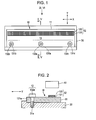
Fig. 1 is a top view that schematically illustrates an example of the structure of a linear scale according to an exemplary embodiment of the invention; -
Fig. 2 is a sectional view taken along the line II-II ofFig. 1 ; -
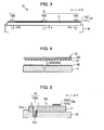
Fig. 3 is an arrow view that illustrates a linear scale according to the embodiment of the invention that is viewed from the arrow direction III ofFig. 1 ; -
Fig. 4 is a diagram that schematically illustrates an example of a manufacturing step of a linear scale according to the embodiment of the invention; -
Fig. 5 is a sectional view that schematically illustrates an example of the structure of a linear scale according to a second embodiment of the invention that is taken along the line V-V ofFig. 1 ; -
Fig. 6 is an arrow view that illustrates a linear scale according to the second embodiment of the invention that is viewed from the arrow direction VI ofFig. 1 ; -
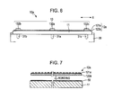
Fig. 7 is a diagram that schematically illustrates an example of a manufacturing step of a linear scale according to the second embodiment of the invention; -
Fig. 8 is a top view that schematically illustrates an example of the structure of a linear scale according to a third embodiment of the invention; -
Fig. 9 is a top view that schematically illustrates an example of the structure of a linear scale according to a fourth embodiment of the invention; -
Fig. 10 is a top view that schematically illustrates an example of the structure of a linear scale according to a fifth embodiment of the invention; -
Fig. 11 is a sectional view that schematically illustrates an example of the structure of a linear scale according to the fifth embodiment of the invention that is taken along the line XI-XI ofFig. 10 ; -
Fig. 12 is an arrow view that illustrates a linear scale according to the fifth embodiment of the invention that is viewed from the arrow direction XII ofFig. 10 ; -
Fig. 13 is a top view that schematically illustrates an example of the structure of a linear scale according to a sixth embodiment of the invention; and -
Fig. 14 is a sectional view taken along the line XIV-XIV ofFig. 13 . - With reference to the accompanying drawings, exemplary embodiments of the present invention will now be explained in detail.
- The structure of a
linear scale 10 according to a first embodiment of the invention is explained first with reference toFigs. 1, 2 , and3 .Fig. 1 is a top view that schematically illustrates an example of the structure of thelinear scale 10.Fig. 2 is a sectional view taken along the line II-II ofFig. 1 .Fig. 3 is an arrow view that illustrates thelinear scale 10 viewed from the arrow direction III ofFig. 1 . - The
linear scale 10 is used for displacement measurement. Specifically, thelinear scale 10 is used for a photoelectric reflective linear encoder. As illustrated inFig. 1 , thelinear scale 10 is provided with a scale table 11, agraduation part 12, and anattachment part 13. - As illustrated in
Figs. 1, 2 , and3 , the scale table 11 has the shape of a substantially rectangular parallelepiped. In the following description, the direction of the long sides of the scale table 11 is referred to as the X direction. The direction of the short sides of the scale table 11 is hereinafter referred to as the Y direction The X direction is the direction in which thelinear scale 10 moves relative to adetector 40 at the time of measurement. - The scale table 11 is made of low expansion ceramics. It is preferable that the low expansion ceramics should have a thermal expansion coefficient α of 0.01 to 0.04 ppm/K (parts per million per Kelvin). For example, oxide ceramics that contains only solid solution crystal made of Li-Mg-Al-Fe-Si-O element can be used. More specifically, a preferred example of the low expansion ceramics is low expansion ceramics manufactured by Nippon Steel Materials Co.,Ltd. (trade name: NEXCERA), which contains MgaLibFecAldSieOf (a: 1.8 to 1.9, b: 0.1 to 0.3, c: 0 to 0.2, d: 3.9 to 4.1, e: 6.0 to 7.0, f: 19 to 23) and has a thermal expansion coefficient α of 0.02 ppm/K. The low expansion ceramics may have the same crystal structure as α-Cordierite in addition to the solid solution to give a greater rigidity. The comparable rigidity of the low expansion ceramics is preferably 50 Gpa/g/cm3 or greater.
- As illustrated in
Fig. 1 , thegraduation part 12 is fixed to the scale table 11 at a position relatively close to one edge of the scale table 11 viewed in the Y direction. Thegraduation part 12 extends in the X direction as illustrated inFig. 3 (andFig. 1 ). Thedetector 40 reads thegraduation part 12 at the time of measurement. Thegraduation part 12 includesgraduations 121, which are read at the time of measurement, and asubstrate 122 on which thegraduations 121 are formed. - The
graduations 121 are bonded to the upper surface of the scale table 11. Thegraduations 121 constitute a stripe pattern that includes a plurality of graduation lines arranged with a predetermined pitch in the X direction. Thegraduations 121 are amplitude grating that is used for detection by a detector that utilizes a tri-grating principle or phase grating that is used for detection by a detector that uses a diffraction optical system. - The
substrate 122 is provided on the upper surface of thegraduations 121. Thesubstrate 122 is made of a transparent material such as glass. Accordingly, a beam of light that is used for measurement can pass through thesubstrate 122. Thesubstrate 122 has the shape of an elongated rectangle. Thesubstrate 122 is elongated in the X direction. - As illustrated in
Figs. 1, 2 , and3 , theattachment part 13 has a structure for fastening the scale table 11 to abase member 30. Theattachment part 13 is provided relatively close to the other edge of the scale table 11 viewed in the Y direction. Theattachment part 13 includes throughholes screws - The through
holes holes holes hole 131a is formed at the X-directional center of the scale table 11, that is, a halfway position in the X direction. The throughholes screws holes base member 30, through the throughholes - Next, with reference to
Fig. 4 , a method for manufacturing thelinear scale 10 according to the first embodiment of the invention is explained below. As a first step, as illustrated inFig. 4 , thegraduations 121 are formed on the lower surface of thesubstrate 122. Next, the lower surface of thegraduations 121 is bonded to the upper surface of the scale table 11. An adhesive 50, for example, a silicone adhesive (KE44T, Manufactured by Shin-Etsu Chemical Co., Ltd.), is used for the attachment of thegraduations 121 to the scale table 11. The adhesion strengthens the mechanical combination of thegraduations 121 and the scale table 11. - In the structure of the
linear scale 10 according to the first embodiment of the invention, since the scale table 11 is made of low expansion ceramics that is far less susceptible to aged deterioration in comparison with other material such as glass, almost no aged deterioration occurs in thegraduation part 12, which is fixed securely to the scale table 11. For this reason, it is possible to perform measurement with a high degree of accuracy. In addition, in the structure of thelinear scale 10 according to the first embodiment of the invention, since the scale table 11 is directly fastened to thebase member 30 by means of the attachment part 13 (which includes the throughholes screws linear scale 10 according to the first embodiment of the invention has a simple structure and can be manufactured at low cost. - In the first embodiment, the
substrate 122 is provided on the upper surface of thegraduations 121. Therefore, thelinear scale 10 according to the first embodiment of the invention has an advantage that it is possible to protect thegraduations 121 from physical shock by means of thesubstrate 122. - Next, with reference to
Figs. 5 and6 , the structure of alinear scale 10a according to a second embodiment of the invention is explained below.Fig. 5 is a sectional view that schematically illustrates an example of the structure of thelinear scale 10a according to the second embodiment of the invention, which is taken along the line V-V.Fig. 6 is an arrow view that illustrates thelinear scale 10a viewed from the arrow direction VI. In the following description of thelinear scale 10a according to the second embodiment of the invention, the same reference numerals are consistently used for the same components as those of thelinear scale 10 according to the first embodiment of the invention so as to omit any redundant explanation. - The
linear scale 10a according to the second embodiment of the invention is different from thelinear scale 10 according to the first embodiment of the invention in that, as illustrated inFigs. 5 and6 ,graduations 121a of agraduation part 12a are formed on the upper surface of asubstrate 122a thereof. Thelinear scale 10a can be used for an optical-type reflective linear encoder like the first embodiment of the invention. Besides such application, thelinear scale 10a may be used for a capacitance-type reflective linear encoder or an electromagnetic-induction reflective linear encoder. - The
graduations 121a of thelinear scale 10a are amplitude grating that is used for detection by a detector that utilizes a tri-grating principle or phase grating that is used for detection by a detector that uses a diffraction optical system like the first embodiment of the invention. Thegraduations 121a may be a random pattern that is used for detection by a capacitance detector or an electromagnetic induction detector. - The
substrate 122a of thegraduation part 12a is bonded to the upper surface of the scale table 11. Thesubstrate 122a is a printed circuit board (PCB) that is made of, for example, ferrous metal, glass epoxy, or the like. Method for Manufacturing Linear Scale According to Second Embodiment - Next, with reference to
Fig. 7 , a method for manufacturing thelinear scale 10a according to the second embodiment of the invention is explained below. As a first step, as illustrated inFig. 7 , thegraduations 121a are formed on the upper surface of thesubstrate 122a. Next, as illustrated therein, the lower surface of thesubstrate 122a is bonded to the upper surface of the scale table 11 by means of the adhesive 50. - The rigidity of the scale table 11 is far greater than that of the
substrate 122a. For this reason, since the precision of the scale table 11 determines its mechanical precision, thelinear scale 10a according to the second embodiment of the invention produces the same advantageous effects as those of the first embodiment of the invention. In addition, since thegraduations 121a are formed on the upper surface of thesubstrate 122a opposite the bonding surface thereof, thelinear scale 10a can be used for a capacitance-type reflective linear encoder or an electromagnetic-induction reflective linear encoder. - Next, with reference to
Fig. 8 , the structure of alinear scale 10b according to a third embodiment of the invention is explained below.Fig. 8 is a top view that schematically illustrates an example of the structure of thelinear scale 10b. In the following description of thelinear scale 10b according to the third embodiment of the invention, the same reference numerals are consistently used for the same components as those of thelinear scale 10 according to the first embodiment of the invention and thelinear scale 10a according to the second embodiment of the invention so as to omit any redundant explanation. - As illustrated in
Fig. 8 , thelinear scale 10b according to the third embodiment of the invention has fourslits - Each of two
slits attachment part 13 to a region near a halfway point in the Y direction. These twoslits hole 131a. The throughhole 131a is formed between theslit 141 and theslit 142. - Each of two
slits attachment part 13 in a bent slit pattern resembling a letter L. The slit 143 "encloses" the throughhole 131b. Theslit 144 encloses the throughhole 131c. Advantageous Effects Produced by Linear Scale According to Third Embodiment - Since the
linear scale 10b according to the third embodiment of the invention has theslits slits graduation part 12. Having theslits linear scale 10b according to the third embodiment of the invention makes it possible to perform measurement with a higher degree of accuracy in comparison with the first and second embodiments of the invention. - Next, with reference to
Fig. 9 , the structure of alinear scale 10c according to a fourth embodiment of the invention is explained below.Fig. 9 is a top view that schematically illustrates an example of the structure of thelinear scale 10c. In the following description of thelinear scale 10c according to the fourth embodiment of the invention, the same reference numerals are consistently used for the same components as those of thelinear scales - As illustrated in
Fig. 9 , besides the twostraight slits linear scale 10c according to the fourth embodiment of the invention has twostraight slits slits linear scale 10b according to the third embodiment of the invention. Thestraight slits - In the structure of the
linear scale 10c according to the fourth embodiment of the invention, the twoslits - Since the two
slits linear scale 10c according to the fourth embodiment of the invention produces the following advantageous effect besides the foregoing advantageous effects. Even in a case where thebase member 30 changes in form, theslits graduation part 12. Having theslits linear scale 10c according to the fourth embodiment of the invention makes it possible to perform measurement with a higher degree of accuracy in comparison with the third embodiment of the invention. - Next, with reference to
Figs. 10, 11, and 12 , the structure of alinear scale 10d according to a fifth embodiment of the invention is explained below.Fig. 10 is a top view that schematically illustrates an example of the structure of thelinear scale 10d.Fig. 11 is a sectional view taken along the line XI-XI ofFig. 10. Fig. 12 is an arrow view that illustrates thelinear scale 10d viewed from the arrow direction XII-XII ofFig. 10 . In the following description of thelinear scale 10d according to the fifth embodiment of the invention, the same reference numerals are consistently used for the same components as those of thelinear scales - The
linear scale 10d according to the fifth embodiment of the invention is different from the linear scale according to the foregoing embodiments of the invention in that, as illustrated inFigs. 10, 11, and 12 , agraduation part 12d includesgraduations 121d only. Thelinear scale 10d is used for, for example, a photoelectric reflective linear encoder. Thelinear scale 10d may be used for a capacitance-type reflective linear encoder or an electromagnetic-induction reflective linear encoder. - The
graduations 121d are formed directly on the upper surface of the scale table 11. Thegraduations 121d are amplitude grating that is used for detection by a detector that utilizes a tri-grating principle or phase grating that is used for detection by a detector that uses a diffraction optical system. Thegraduations 121d may be a random pattern that is used for detection by a capacitance detector or an electromagnetic induction detector. Advantageous Effects Produced by Linear Scale According to Fifth Embodiment - Since the
graduations 121d are formed directly on the upper surface of the scale table 11, thelinear scale 10d according to the fifth embodiment of the invention offers an advantage in that thegraduations 121d are less likely to be affected by aged deterioration in comparison with thegraduations substrate linear scale 10d according to the fifth embodiment of the invention makes it possible to perform measurement with a higher degree of accuracy in comparison with the first and - Next, with reference to
Figs. 13 and 14 , the structure of alinear scale 10e according to a sixth embodiment of the invention is explained below.Fig. 13 is a top view that schematically illustrates an example of the structure of thelinear scale 10e.Fig. 14 is a sectional view taken along the line XIV-XIV ofFig. 13 . In the following description of thelinear scale 10e according to the sixth embodiment of the invention, the same reference numerals are consistently used for the same components as those of thelinear scales - In the structure of the
linear scale 10e according to the sixth embodiment of the invention, as illustrated inFigs. 13 and 14 , anattachment part 13e includes through holes 131be and 131ce as a substitute for the throughholes hole attachment part 13e includes anelastic member 133b and abush 134b inside the through hole 131be and further includes anelastic member 133c and abush 134c inside the through hole 131ce. - Each of the
elastic members elastic members elastic members - The
bushes elastic members bushes upper part 134A and alower part 134B. Theupper part 134A has a first outside diameter. Thelower part 134B has a second outside diameter. The first outside diameter of theupper part 134A is larger than the diameter of the through hole 131be, 131ce of the scale table 11. The second outside diameter of thelower part 134B is substantially equal to the inner diameter of theelastic member screws holes base member 30, through thebushes - In the structure of the
linear scale 10e according to the sixth embodiment of the invention, the scale table 11 is fastened to thebase member 30 by means of thescrews elastic members bushes elastic members graduation part 12. Thus, thelinear scale 10e according to the sixth embodiment of the invention, which is provided with theelastic members bushes - Although exemplary embodiments of the present invention are described above, needless to say, the invention is not restricted to the exemplary embodiments described herein; the invention can be implemented in a variety of variations, modifications, additions, or the like without departing from the gist, the spirit, and the scope thereof.
- As explained in detail above, a linear scale that is capable of performing measurement with a high degree of accuracy while achieving production at low cost is provided.
Claims (6)
- A linear scale that is used for displacement measurement, comprising:a scale board that is made of low expansion ceramics;a graduation unit that is fixed to an upper surface of the scale board, the graduation unit being read at the time of measurement; andan attachment unit that attaches the scale board to a base member.
- The linear scale according to Claim 1, wherein the low expansion ceramics is oxide ceramics containing solid solution crystal made of any of Li-Mg-Al-Fe-Si-O element.
- The linear scale according to Claim 1 or Claim 2, wherein the scale board has a slit that is formed near the attachment unit.
- The linear scale according to Claim 3, wherein the scale board has a first area located at one edge side of the scale board and a second area located at the other edge side of the scale board; the graduation unit is provided at the first area; the attachment unit is provided at the second area; and the slit is formed between the first area and the second area.
- The linear scale according to any of the preceding claims, wherein the attachment unit includes a through hole that is formed through the scale board and a screw that is fitted in a threaded hole through the through hole; and the threaded hole is formed in the base member.
- The linear scale according to any of the preceding claims, wherein the attachment unit includes a through hole that is formed through the scale board, an elastic member that has the shape of a ring and is fitted in the through hole, a bush that is fitted in the elastic member, and a screw that is fitted in a threaded hole through the bush; and the threaded hole is formed in the base member.
Applications Claiming Priority (1)
| Application Number | Priority Date | Filing Date | Title |
|---|---|---|---|
| JP2009071525A JP5162800B2 (en) | 2009-03-24 | 2009-03-24 | Linear scale |
Publications (3)
| Publication Number | Publication Date |
|---|---|
| EP2233893A2 true EP2233893A2 (en) | 2010-09-29 |
| EP2233893A3 EP2233893A3 (en) | 2014-12-24 |
| EP2233893B1 EP2233893B1 (en) | 2016-10-19 |
Family
ID=42421970
Family Applications (1)
| Application Number | Title | Priority Date | Filing Date |
|---|---|---|---|
| EP10157443.2A Not-in-force EP2233893B1 (en) | 2009-03-24 | 2010-03-23 | Linear Scale |
Country Status (3)
| Country | Link |
|---|---|
| US (1) | US7934324B2 (en) |
| EP (1) | EP2233893B1 (en) |
| JP (1) | JP5162800B2 (en) |
Cited By (3)
| Publication number | Priority date | Publication date | Assignee | Title |
|---|---|---|---|---|
| CN104819731A (en) * | 2014-02-04 | 2015-08-05 | 株式会社三丰 | Linear encoder |
| WO2016041919A1 (en) * | 2014-09-15 | 2016-03-24 | Deckel Maho Pfronten Gmbh | Position measuring device for use on a machine tool |
| EP4560270A1 (en) | 2023-11-23 | 2025-05-28 | Etel S.A. | Scale support for an encoder scale and linear encoder comprising such scale support |
Families Citing this family (7)
| Publication number | Priority date | Publication date | Assignee | Title |
|---|---|---|---|---|
| DE102009044917A1 (en) * | 2009-09-23 | 2011-04-07 | Dr. Johannes Heidenhain Gmbh | Length measuring device |
| US8739424B2 (en) * | 2011-06-24 | 2014-06-03 | Mitutoyo Corporation | Structure for protecting scale graduations |
| JP2014224705A (en) * | 2013-05-15 | 2014-12-04 | キヤノン株式会社 | Scale holding device and encoder |
| JP6215660B2 (en) * | 2013-11-13 | 2017-10-18 | 株式会社ジェイテクト | Grinder |
| JP2016165785A (en) * | 2015-03-10 | 2016-09-15 | 株式会社ディスコ | Movable device and processing device |
| JP6738661B2 (en) * | 2016-06-16 | 2020-08-12 | 株式会社ミツトヨ | Industrial machinery |
| JP6895332B2 (en) * | 2017-07-05 | 2021-06-30 | 株式会社ミツトヨ | Linear scale |
Citations (1)
| Publication number | Priority date | Publication date | Assignee | Title |
|---|---|---|---|---|
| JP2007183254A (en) | 2005-12-06 | 2007-07-19 | Mitsutoyo Corp | Scale for displacement measuring device |
Family Cites Families (14)
| Publication number | Priority date | Publication date | Assignee | Title |
|---|---|---|---|---|
| DE3625795A1 (en) * | 1986-07-30 | 1988-02-04 | Heidenhain Gmbh Dr Johannes | LENGTH MEASURING DEVICE |
| CH679334A5 (en) * | 1989-09-11 | 1992-01-31 | Weber Hans R | |
| DE4320728C2 (en) * | 1993-06-23 | 2001-08-02 | Heidenhain Gmbh Dr Johannes | Position measuring device |
| DE19821558B4 (en) * | 1997-08-08 | 2007-09-13 | Dr. Johannes Heidenhain Gmbh | Scale and method for the production of a scale and position measuring device |
| DE19854318A1 (en) * | 1998-11-25 | 2000-05-31 | Heidenhain Gmbh Dr Johannes | Length measuring device |
| JP4024600B2 (en) * | 2002-06-25 | 2007-12-19 | 株式会社ミツトヨ | Frame multipoint fixed type unit type linear displacement measuring device and its fixing method |
| TWI310326B (en) * | 2005-10-11 | 2009-06-01 | Gsi Group Corp | Optical metrological scale and laser-based manufacturing method therefor |
| ES2535851T3 (en) * | 2005-11-04 | 2015-05-18 | Dr. Johannes Heidenhain Gmbh | Procedure for fixing a measurement scale on a support, adapted measurement scale as well as support with this measurement scale |
| US7707739B2 (en) * | 2005-11-04 | 2010-05-04 | Dr. Johannes Heidenhain Gmbh | Method for attaching a scale to a carrier, a scale, and carrier having a scale |
| JP4982554B2 (en) * | 2006-03-29 | 2012-07-25 | ドクトル・ヨハネス・ハイデンハイン・ゲゼルシヤフト・ミツト・ベシユレンクテル・ハフツング | Method for holding scale on carrier and assembly comprising carrier and scale |
| JP2007314363A (en) * | 2006-05-24 | 2007-12-06 | Nippon Steel Materials Co Ltd | Low thermal expansion ceramic material and manufacturing method thereof |
| JP2009047514A (en) * | 2007-08-17 | 2009-03-05 | Sony Corp | Position detector mounting structure |
| US7971487B2 (en) * | 2008-05-02 | 2011-07-05 | Carlen Controls, Inc. | Linear position transducer with wireless read head |
| TW201003053A (en) * | 2008-07-10 | 2010-01-16 | Nikon Corp | Deformation measuring apparatus, exposure apparatus, jig for deformation measuring apparatus, position measuring method and device manufacturing method |
-
2009
- 2009-03-24 JP JP2009071525A patent/JP5162800B2/en not_active Expired - Fee Related
-
2010
- 2010-03-23 EP EP10157443.2A patent/EP2233893B1/en not_active Not-in-force
- 2010-03-23 US US12/729,565 patent/US7934324B2/en active Active
Patent Citations (1)
| Publication number | Priority date | Publication date | Assignee | Title |
|---|---|---|---|---|
| JP2007183254A (en) | 2005-12-06 | 2007-07-19 | Mitsutoyo Corp | Scale for displacement measuring device |
Cited By (9)
| Publication number | Priority date | Publication date | Assignee | Title |
|---|---|---|---|---|
| CN104819731A (en) * | 2014-02-04 | 2015-08-05 | 株式会社三丰 | Linear encoder |
| EP2902750A1 (en) * | 2014-02-04 | 2015-08-05 | Mitutoyo Corporation | Linear encoder |
| US9506778B2 (en) | 2014-02-04 | 2016-11-29 | Mitutoyo Corporation | Linear encoder |
| CN104819731B (en) * | 2014-02-04 | 2019-01-25 | 株式会社三丰 | Linear encoder |
| WO2016041919A1 (en) * | 2014-09-15 | 2016-03-24 | Deckel Maho Pfronten Gmbh | Position measuring device for use on a machine tool |
| CN106715044A (en) * | 2014-09-15 | 2017-05-24 | 德克尔马霍普夫龙滕有限公司 | Position measuring device for use on a machine tool |
| US20170252885A1 (en) * | 2014-09-15 | 2017-09-07 | Deckel Maho Pfronten Gmbh | Position measuring device for use on a machine tool |
| US10391601B2 (en) | 2014-09-15 | 2019-08-27 | Deckel Maho Pfronten Gmbh | Position measuring device for use on a machine tool |
| EP4560270A1 (en) | 2023-11-23 | 2025-05-28 | Etel S.A. | Scale support for an encoder scale and linear encoder comprising such scale support |
Also Published As
| Publication number | Publication date |
|---|---|
| EP2233893A3 (en) | 2014-12-24 |
| US20100242295A1 (en) | 2010-09-30 |
| JP5162800B2 (en) | 2013-03-13 |
| EP2233893B1 (en) | 2016-10-19 |
| JP2010223767A (en) | 2010-10-07 |
| US7934324B2 (en) | 2011-05-03 |
Similar Documents
| Publication | Publication Date | Title |
|---|---|---|
| EP2233893B1 (en) | Linear Scale | |
| CN107445133B (en) | Compact load cell device with low sensitivity to thermo-mechanical package stress | |
| KR101534393B1 (en) | Electronic quartz resonator module provided with shock resistant securing means | |
| US8671752B2 (en) | Sensor system | |
| KR20030088061A (en) | Method and apparatus for force-based touch input | |
| KR20040047684A (en) | Acceleration sensor | |
| EP1407278B1 (en) | Acceleration sensor | |
| US5630283A (en) | Linear or angular encoder | |
| JP4230810B2 (en) | Measuring device | |
| JPH08178694A (en) | Scale for displacement sensor | |
| US8257119B2 (en) | Systems and methods for affixing a silicon device to a support structure | |
| US20060137461A1 (en) | Pressure sensor with integrated structure | |
| US10788387B2 (en) | Component having a micromechanical sensor module | |
| US10209103B2 (en) | Linear encoder | |
| JP2004119624A (en) | Circuit board | |
| CN102334013B (en) | Module for an angle measuring device and corresponding angle measuring device | |
| CN111912363B (en) | Assembly for fastening a carrier with a measuring scale at the end to a mounting surface of a base body | |
| JP4401847B2 (en) | Displacement measuring device | |
| US7997133B2 (en) | Temperature compensating sensor | |
| US20230392914A1 (en) | Assembly for position measurement | |
| RU2421736C1 (en) | Accelerometer | |
| JP2006153516A (en) | Acceleration sensor | |
| SU1642284A1 (en) | Pressure pickup | |
| JPH0650794Y2 (en) | Electronic timepiece circuit board and electronic timepiece | |
| Voss et al. | Modern scale based magneto resistive sensors systems |
Legal Events
| Date | Code | Title | Description |
|---|---|---|---|
| PUAI | Public reference made under article 153(3) epc to a published international application that has entered the european phase |
Free format text: ORIGINAL CODE: 0009012 |
|
| AK | Designated contracting states |
Kind code of ref document: A2 Designated state(s): AT BE BG CH CY CZ DE DK EE ES FI FR GB GR HR HU IE IS IT LI LT LU LV MC MK MT NL NO PL PT RO SE SI SK SM TR |
|
| AX | Request for extension of the european patent |
Extension state: AL BA ME RS |
|
| PUAL | Search report despatched |
Free format text: ORIGINAL CODE: 0009013 |
|
| AK | Designated contracting states |
Kind code of ref document: A3 Designated state(s): AT BE BG CH CY CZ DE DK EE ES FI FR GB GR HR HU IE IS IT LI LT LU LV MC MK MT NL NO PL PT RO SE SI SK SM TR |
|
| AX | Request for extension of the european patent |
Extension state: AL BA ME RS |
|
| RIC1 | Information provided on ipc code assigned before grant |
Ipc: G01D 5/347 20060101AFI20141117BHEP |
|
| 17P | Request for examination filed |
Effective date: 20150216 |
|
| RBV | Designated contracting states (corrected) |
Designated state(s): AT BE BG CH CY CZ DE DK EE ES FI FR GB GR HR HU IE IS IT LI LT LU LV MC MK MT NL NO PL PT RO SE SI SK SM TR |
|
| 17Q | First examination report despatched |
Effective date: 20160226 |
|
| GRAP | Despatch of communication of intention to grant a patent |
Free format text: ORIGINAL CODE: EPIDOSNIGR1 |
|
| INTG | Intention to grant announced |
Effective date: 20160801 |
|
| GRAS | Grant fee paid |
Free format text: ORIGINAL CODE: EPIDOSNIGR3 |
|
| GRAA | (expected) grant |
Free format text: ORIGINAL CODE: 0009210 |
|
| AK | Designated contracting states |
Kind code of ref document: B1 Designated state(s): AT BE BG CH CY CZ DE DK EE ES FI FR GB GR HR HU IE IS IT LI LT LU LV MC MK MT NL NO PL PT RO SE SI SK SM TR |
|
| REG | Reference to a national code |
Ref country code: GB Ref legal event code: FG4D |
|
| REG | Reference to a national code |
Ref country code: CH Ref legal event code: EP |
|
| REG | Reference to a national code |
Ref country code: AT Ref legal event code: REF Ref document number: 838736 Country of ref document: AT Kind code of ref document: T Effective date: 20161115 |
|
| REG | Reference to a national code |
Ref country code: IE Ref legal event code: FG4D |
|
| REG | Reference to a national code |
Ref country code: DE Ref legal event code: R096 Ref document number: 602010037259 Country of ref document: DE |
|
| REG | Reference to a national code |
Ref country code: NL Ref legal event code: MP Effective date: 20161019 |
|
| REG | Reference to a national code |
Ref country code: LT Ref legal event code: MG4D |
|
| PG25 | Lapsed in a contracting state [announced via postgrant information from national office to epo] |
Ref country code: LV Free format text: LAPSE BECAUSE OF FAILURE TO SUBMIT A TRANSLATION OF THE DESCRIPTION OR TO PAY THE FEE WITHIN THE PRESCRIBED TIME-LIMIT Effective date: 20161019 |
|
| REG | Reference to a national code |
Ref country code: AT Ref legal event code: MK05 Ref document number: 838736 Country of ref document: AT Kind code of ref document: T Effective date: 20161019 |
|
| PG25 | Lapsed in a contracting state [announced via postgrant information from national office to epo] |
Ref country code: LT Free format text: LAPSE BECAUSE OF FAILURE TO SUBMIT A TRANSLATION OF THE DESCRIPTION OR TO PAY THE FEE WITHIN THE PRESCRIBED TIME-LIMIT Effective date: 20161019 Ref country code: NO Free format text: LAPSE BECAUSE OF FAILURE TO SUBMIT A TRANSLATION OF THE DESCRIPTION OR TO PAY THE FEE WITHIN THE PRESCRIBED TIME-LIMIT Effective date: 20170119 Ref country code: SE Free format text: LAPSE BECAUSE OF FAILURE TO SUBMIT A TRANSLATION OF THE DESCRIPTION OR TO PAY THE FEE WITHIN THE PRESCRIBED TIME-LIMIT Effective date: 20161019 Ref country code: GR Free format text: LAPSE BECAUSE OF FAILURE TO SUBMIT A TRANSLATION OF THE DESCRIPTION OR TO PAY THE FEE WITHIN THE PRESCRIBED TIME-LIMIT Effective date: 20170120 |
|
| PG25 | Lapsed in a contracting state [announced via postgrant information from national office to epo] |
Ref country code: FI Free format text: LAPSE BECAUSE OF FAILURE TO SUBMIT A TRANSLATION OF THE DESCRIPTION OR TO PAY THE FEE WITHIN THE PRESCRIBED TIME-LIMIT Effective date: 20161019 Ref country code: IS Free format text: LAPSE BECAUSE OF FAILURE TO SUBMIT A TRANSLATION OF THE DESCRIPTION OR TO PAY THE FEE WITHIN THE PRESCRIBED TIME-LIMIT Effective date: 20170219 Ref country code: HR Free format text: LAPSE BECAUSE OF FAILURE TO SUBMIT A TRANSLATION OF THE DESCRIPTION OR TO PAY THE FEE WITHIN THE PRESCRIBED TIME-LIMIT Effective date: 20161019 Ref country code: NL Free format text: LAPSE BECAUSE OF FAILURE TO SUBMIT A TRANSLATION OF THE DESCRIPTION OR TO PAY THE FEE WITHIN THE PRESCRIBED TIME-LIMIT Effective date: 20161019 Ref country code: AT Free format text: LAPSE BECAUSE OF FAILURE TO SUBMIT A TRANSLATION OF THE DESCRIPTION OR TO PAY THE FEE WITHIN THE PRESCRIBED TIME-LIMIT Effective date: 20161019 Ref country code: BE Free format text: LAPSE BECAUSE OF FAILURE TO SUBMIT A TRANSLATION OF THE DESCRIPTION OR TO PAY THE FEE WITHIN THE PRESCRIBED TIME-LIMIT Effective date: 20161019 Ref country code: PT Free format text: LAPSE BECAUSE OF FAILURE TO SUBMIT A TRANSLATION OF THE DESCRIPTION OR TO PAY THE FEE WITHIN THE PRESCRIBED TIME-LIMIT Effective date: 20170220 Ref country code: PL Free format text: LAPSE BECAUSE OF FAILURE TO SUBMIT A TRANSLATION OF THE DESCRIPTION OR TO PAY THE FEE WITHIN THE PRESCRIBED TIME-LIMIT Effective date: 20161019 Ref country code: ES Free format text: LAPSE BECAUSE OF FAILURE TO SUBMIT A TRANSLATION OF THE DESCRIPTION OR TO PAY THE FEE WITHIN THE PRESCRIBED TIME-LIMIT Effective date: 20161019 |
|
| REG | Reference to a national code |
Ref country code: DE Ref legal event code: R097 Ref document number: 602010037259 Country of ref document: DE |
|
| PG25 | Lapsed in a contracting state [announced via postgrant information from national office to epo] |
Ref country code: RO Free format text: LAPSE BECAUSE OF FAILURE TO SUBMIT A TRANSLATION OF THE DESCRIPTION OR TO PAY THE FEE WITHIN THE PRESCRIBED TIME-LIMIT Effective date: 20161019 Ref country code: SK Free format text: LAPSE BECAUSE OF FAILURE TO SUBMIT A TRANSLATION OF THE DESCRIPTION OR TO PAY THE FEE WITHIN THE PRESCRIBED TIME-LIMIT Effective date: 20161019 Ref country code: DK Free format text: LAPSE BECAUSE OF FAILURE TO SUBMIT A TRANSLATION OF THE DESCRIPTION OR TO PAY THE FEE WITHIN THE PRESCRIBED TIME-LIMIT Effective date: 20161019 Ref country code: EE Free format text: LAPSE BECAUSE OF FAILURE TO SUBMIT A TRANSLATION OF THE DESCRIPTION OR TO PAY THE FEE WITHIN THE PRESCRIBED TIME-LIMIT Effective date: 20161019 Ref country code: CZ Free format text: LAPSE BECAUSE OF FAILURE TO SUBMIT A TRANSLATION OF THE DESCRIPTION OR TO PAY THE FEE WITHIN THE PRESCRIBED TIME-LIMIT Effective date: 20161019 |
|
| PLBE | No opposition filed within time limit |
Free format text: ORIGINAL CODE: 0009261 |
|
| STAA | Information on the status of an ep patent application or granted ep patent |
Free format text: STATUS: NO OPPOSITION FILED WITHIN TIME LIMIT |
|
| PG25 | Lapsed in a contracting state [announced via postgrant information from national office to epo] |
Ref country code: IT Free format text: LAPSE BECAUSE OF FAILURE TO SUBMIT A TRANSLATION OF THE DESCRIPTION OR TO PAY THE FEE WITHIN THE PRESCRIBED TIME-LIMIT Effective date: 20161019 Ref country code: SM Free format text: LAPSE BECAUSE OF FAILURE TO SUBMIT A TRANSLATION OF THE DESCRIPTION OR TO PAY THE FEE WITHIN THE PRESCRIBED TIME-LIMIT Effective date: 20161019 Ref country code: BG Free format text: LAPSE BECAUSE OF FAILURE TO SUBMIT A TRANSLATION OF THE DESCRIPTION OR TO PAY THE FEE WITHIN THE PRESCRIBED TIME-LIMIT Effective date: 20170119 |
|
| 26N | No opposition filed |
Effective date: 20170720 |
|
| REG | Reference to a national code |
Ref country code: CH Ref legal event code: PL |
|
| PG25 | Lapsed in a contracting state [announced via postgrant information from national office to epo] |
Ref country code: SI Free format text: LAPSE BECAUSE OF FAILURE TO SUBMIT A TRANSLATION OF THE DESCRIPTION OR TO PAY THE FEE WITHIN THE PRESCRIBED TIME-LIMIT Effective date: 20161019 Ref country code: MC Free format text: LAPSE BECAUSE OF FAILURE TO SUBMIT A TRANSLATION OF THE DESCRIPTION OR TO PAY THE FEE WITHIN THE PRESCRIBED TIME-LIMIT Effective date: 20161019 |
|
| REG | Reference to a national code |
Ref country code: IE Ref legal event code: MM4A |
|
| REG | Reference to a national code |
Ref country code: FR Ref legal event code: ST Effective date: 20171130 |
|
| PG25 | Lapsed in a contracting state [announced via postgrant information from national office to epo] |
Ref country code: FR Free format text: LAPSE BECAUSE OF NON-PAYMENT OF DUE FEES Effective date: 20170331 Ref country code: LU Free format text: LAPSE BECAUSE OF NON-PAYMENT OF DUE FEES Effective date: 20170323 |
|
| PG25 | Lapsed in a contracting state [announced via postgrant information from national office to epo] |
Ref country code: IE Free format text: LAPSE BECAUSE OF NON-PAYMENT OF DUE FEES Effective date: 20170323 Ref country code: LI Free format text: LAPSE BECAUSE OF NON-PAYMENT OF DUE FEES Effective date: 20170331 Ref country code: CH Free format text: LAPSE BECAUSE OF NON-PAYMENT OF DUE FEES Effective date: 20170331 |
|
| PG25 | Lapsed in a contracting state [announced via postgrant information from national office to epo] |
Ref country code: MT Free format text: LAPSE BECAUSE OF NON-PAYMENT OF DUE FEES Effective date: 20170323 |
|
| PG25 | Lapsed in a contracting state [announced via postgrant information from national office to epo] |
Ref country code: HU Free format text: LAPSE BECAUSE OF FAILURE TO SUBMIT A TRANSLATION OF THE DESCRIPTION OR TO PAY THE FEE WITHIN THE PRESCRIBED TIME-LIMIT; INVALID AB INITIO Effective date: 20100323 |
|
| PG25 | Lapsed in a contracting state [announced via postgrant information from national office to epo] |
Ref country code: CY Free format text: LAPSE BECAUSE OF NON-PAYMENT OF DUE FEES Effective date: 20161019 |
|
| PG25 | Lapsed in a contracting state [announced via postgrant information from national office to epo] |
Ref country code: MK Free format text: LAPSE BECAUSE OF FAILURE TO SUBMIT A TRANSLATION OF THE DESCRIPTION OR TO PAY THE FEE WITHIN THE PRESCRIBED TIME-LIMIT Effective date: 20161019 |
|
| PG25 | Lapsed in a contracting state [announced via postgrant information from national office to epo] |
Ref country code: TR Free format text: LAPSE BECAUSE OF FAILURE TO SUBMIT A TRANSLATION OF THE DESCRIPTION OR TO PAY THE FEE WITHIN THE PRESCRIBED TIME-LIMIT Effective date: 20161019 |
|
| PGFP | Annual fee paid to national office [announced via postgrant information from national office to epo] |
Ref country code: GB Payment date: 20230321 Year of fee payment: 14 Ref country code: DE Payment date: 20220620 Year of fee payment: 14 |
|
| REG | Reference to a national code |
Ref country code: DE Ref legal event code: R119 Ref document number: 602010037259 Country of ref document: DE |
|
| GBPC | Gb: european patent ceased through non-payment of renewal fee |
Effective date: 20240323 |
|
| PG25 | Lapsed in a contracting state [announced via postgrant information from national office to epo] |
Ref country code: DE Free format text: LAPSE BECAUSE OF NON-PAYMENT OF DUE FEES Effective date: 20241001 |
|
| PG25 | Lapsed in a contracting state [announced via postgrant information from national office to epo] |
Ref country code: GB Free format text: LAPSE BECAUSE OF NON-PAYMENT OF DUE FEES Effective date: 20240323 |
|
| PG25 | Lapsed in a contracting state [announced via postgrant information from national office to epo] |
Ref country code: GB Free format text: LAPSE BECAUSE OF NON-PAYMENT OF DUE FEES Effective date: 20240323 Ref country code: DE Free format text: LAPSE BECAUSE OF NON-PAYMENT OF DUE FEES Effective date: 20241001 |